EP2393077A2 - Display apparatus - Google Patents
Display apparatus Download PDFInfo
- Publication number
- EP2393077A2 EP2393077A2 EP11168213A EP11168213A EP2393077A2 EP 2393077 A2 EP2393077 A2 EP 2393077A2 EP 11168213 A EP11168213 A EP 11168213A EP 11168213 A EP11168213 A EP 11168213A EP 2393077 A2 EP2393077 A2 EP 2393077A2
- Authority
- EP
- European Patent Office
- Prior art keywords
- unit
- complex member
- convex portion
- substrate
- display apparatus
- Prior art date
- Legal status (The legal status is an assumption and is not a legal conclusion. Google has not performed a legal analysis and makes no representation as to the accuracy of the status listed.)
- Withdrawn
Links
Images




Classifications
-
- H—ELECTRICITY
- H10—SEMICONDUCTOR DEVICES; ELECTRIC SOLID-STATE DEVICES NOT OTHERWISE PROVIDED FOR
- H10K—ORGANIC ELECTRIC SOLID-STATE DEVICES
- H10K59/00—Integrated devices, or assemblies of multiple devices, comprising at least one organic light-emitting element covered by group H10K50/00
- H10K59/80—Constructional details
- H10K59/87—Passivation; Containers; Encapsulations
- H10K59/871—Self-supporting sealing arrangements
- H10K59/872—Containers
-
- G—PHYSICS
- G09—EDUCATION; CRYPTOGRAPHY; DISPLAY; ADVERTISING; SEALS
- G09F—DISPLAYING; ADVERTISING; SIGNS; LABELS OR NAME-PLATES; SEALS
- G09F9/00—Indicating arrangements for variable information in which the information is built-up on a support by selection or combination of individual elements
- G09F9/30—Indicating arrangements for variable information in which the information is built-up on a support by selection or combination of individual elements in which the desired character or characters are formed by combining individual elements
-
- G—PHYSICS
- G09—EDUCATION; CRYPTOGRAPHY; DISPLAY; ADVERTISING; SEALS
- G09F—DISPLAYING; ADVERTISING; SIGNS; LABELS OR NAME-PLATES; SEALS
- G09F9/00—Indicating arrangements for variable information in which the information is built-up on a support by selection or combination of individual elements
- G09F9/30—Indicating arrangements for variable information in which the information is built-up on a support by selection or combination of individual elements in which the desired character or characters are formed by combining individual elements
- G09F9/35—Indicating arrangements for variable information in which the information is built-up on a support by selection or combination of individual elements in which the desired character or characters are formed by combining individual elements being liquid crystals
-
- H—ELECTRICITY
- H04—ELECTRIC COMMUNICATION TECHNIQUE
- H04N—PICTORIAL COMMUNICATION, e.g. TELEVISION
- H04N5/00—Details of television systems
- H04N5/64—Constructional details of receivers, e.g. cabinets or dust covers
-
- H—ELECTRICITY
- H10—SEMICONDUCTOR DEVICES; ELECTRIC SOLID-STATE DEVICES NOT OTHERWISE PROVIDED FOR
- H10K—ORGANIC ELECTRIC SOLID-STATE DEVICES
- H10K59/00—Integrated devices, or assemblies of multiple devices, comprising at least one organic light-emitting element covered by group H10K50/00
- H10K59/80—Constructional details
- H10K59/87—Passivation; Containers; Encapsulations
- H10K59/871—Self-supporting sealing arrangements
-
- H—ELECTRICITY
- H10—SEMICONDUCTOR DEVICES; ELECTRIC SOLID-STATE DEVICES NOT OTHERWISE PROVIDED FOR
- H10K—ORGANIC ELECTRIC SOLID-STATE DEVICES
- H10K59/00—Integrated devices, or assemblies of multiple devices, comprising at least one organic light-emitting element covered by group H10K50/00
- H10K59/80—Constructional details
- H10K59/87—Passivation; Containers; Encapsulations
- H10K59/871—Self-supporting sealing arrangements
- H10K59/8721—Metallic sealing arrangements
-
- H—ELECTRICITY
- H10—SEMICONDUCTOR DEVICES; ELECTRIC SOLID-STATE DEVICES NOT OTHERWISE PROVIDED FOR
- H10K—ORGANIC ELECTRIC SOLID-STATE DEVICES
- H10K59/00—Integrated devices, or assemblies of multiple devices, comprising at least one organic light-emitting element covered by group H10K50/00
- H10K59/80—Constructional details
- H10K59/87—Passivation; Containers; Encapsulations
- H10K59/871—Self-supporting sealing arrangements
- H10K59/8722—Peripheral sealing arrangements, e.g. adhesives, sealants
Definitions
- aspects of the present invention relate to display apparatuses, and more particularly, to display apparatuses including an encapsulation unit having improved rigidity.
- a flat display apparatus includes a display unit on a lower substrate and an encapsulation substrate disposed on the display unit to protect the display unit. Also, the sealing unit is disposed between the lower substrate and the encapsulation substrate.
- the flat display apparatus is easily deformed or damaged by heat. To prevent this damage, a thick lower substrate or a thick encapsulation substrate may be formed. However, in this case, if an external force due to thermal residual stress of the sealing unit is applied to the flat display apparatus, a rigidity of the display apparatus may be greatly weakened and disbanding may occur along the sealing unit due to a peel stress.
- aspects of the present invention provide display apparatuses including an encapsulation unit having an improved structure for increasing the rigidity of the encapsulation unit by using a reinforcement member.
- a display apparatus including a display unit disposed on a substrate; an encapsulation facing the display unit including: a metal layer; and a complex member, including a base unit and a convex portion that protrudes upward from the base unit.
- the display apparatus may further include a sealing unit disposed between the substrate and the encapsulation unit and apart from the display unit, the sealing unit bonding the substrate and the encapsulation unit to the sealing unit.
- the sealing unit may comprise an epoxy resin.
- the convex portion may extend from the base unit in a direction away from the substrate and wherein the convex portion has a shape of a rectangular plate.
- the convex portion may have a shape of a square plate.
- the convex portion may have a shape of a rectangular ring.
- the convex portion may have a shape of a square ring.
- the convex portion may comprise: a first convex portion extending from the base unit in a direction away from the substrate and having a shape of a rectangular plate; and a second convex portion having a shape of an oval ring, an X-shape, or a stripe shape, and protruding upward from the first convex portion.
- the first convex portion may have a shape of a square plate.
- the convex portion may further comprise a protrusion protruding from an upper surface.
- the convex portion may further comprise an extension portion extending from an edge of the encapsulation unit and surrounding an edge of the substrate.
- the complex member may include a resin matrix and carbon fibers, wherein the metal layer is disposed nearer to the substrate than the complex member is.
- the carbon fibers may comprise first carbon fibers arranged in a first direction and second carbon fibers arranged in a second direction crossing the first direction.
- the carbon fibers may be woven by being arranged in a horizontal direction and a vertical direction.
- a thermal expansion rate of the carbon fibers is smaller than a thermal expansion rate of the substrate.
- the complex member may be formed of layers each including the resin matrix and the carbon fibers.
- some of the carbon fibers are arranged in at least one of the layers in a first direction, and others of the carbon fibers are arranged in another layer of the layers in a second direction, and the first direction and the second direction cross each other.
- the first direction and second direction may cross each other at right angles; that is, the second direction may be perpendicular to the second direction.
- a display apparatus including: a display unit disposed on a substrate; an encapsulation unit facing the display unit, the encapsulation unit including: a metal layer; a complex member; and at least one rib formed on an upper surface of the complex member; and a sealing unit disposed between the substrate and the encapsulation unit and apart from the display unit to bond the substrate and the encapsulation unit to the sealing unit.
- the rib may extend in a lengthwise direction of the complex member.
- the complex member may include a protrusion protruding from an upper surface.
- the complex member may include an extension portion extending from an edge of the encapsulation unit to surround an edge of the substrate.
- the complex member may include: a resin matrix; and carbon fibers, wherein the metal layer is disposed nearer to the substrate than the complex member is.
- a display apparatus including: a display unit disposed on a substrate; an encapsulation unit facing the display unit, the encapsulation unit comprising: a metal layer; a complex member; and a reinforcement member formed on an upper surface of the complex member; and a sealing unit disposed apart from the display unit between the substrate and the encapsulation unit to bond the substrate and the encapsulation unit to the sealing unit.
- the reinforcement member may be a convex portion protruding upwards from a base unit of the complex member, and wherein the reinforcement member is formed as a single unit with the complex member.
- the reinforcement member may be at least one rib that is formed on an upper surface of the complex member.
- FIG. 1 is a cross-sectional view of a display apparatus 100A, according to an embodiment of the present invention.
- FIGS. 2 and 3 are schematic views illustrating a complex member 180A illustrated in FIG. 1 .
- the display apparatus 100A includes a substrate 110, a display unit 130, an encapsulation unit 190A, and a sealing unit 150.
- the substrate 110 is formed of a transparent glass having SiO 2 as a main component.
- aspects of the present invention are not limited thereto and may also be formed of other transparent plastic materials.
- the plastic material of the substrate 110 include polyethersulphone (PES), polyacrylate (PAR), polyetherimide (PEI), polyethyelenen napthalate (PEN), polyethyeleneterepthalate (PET), polyphenylene sulfide (PPS), polyallylate, polyimide, poly carbonate (PC), cellulose triacetate (TAC), cellulose acetate propionate (CAP), and other similar materials.
- a plurality of processes are performed to form the display unit 130 on the substrate 110, and heat is applied during these processes, which causes the substrate 110 to expand.
- the expansion of the substrate 110 reduces durability of the display apparatus 100A and precision of the display unit 130. Accordingly, the substrate 110 has a low thermal expansion rate, for example, 3*10 -6 /K to 4*10 -6 /K.
- the display unit 130 comprises an organic light emitting device, a liquid crystal display apparatus, etc., and is disposed on the substrate 110.
- the encapsulation unit 190A is disposed so as to face the display unit 130.
- the encapsulation unit 190A protects the display unit 130 from water or oxygen, or other similar impurities or elements, from the outside.
- the encapsulation unit 190A includes a metal layer 170 and a complex member 180A.
- the complex member 180A is formed on the metal layer 170. That is, the complex member 180A is disposed farther from the display unit 130 than the metal layer 170 is.
- the sealing unit 150 is hardened by heat to bond both the substrate 110 and the encapsulation unit 190A to the sealing unit 150.
- the encapsulation unit 190A may expand while heat is applied to the sealing unit 150. If the degree to which the encapsulation unit 190A is expanded by the heat is increased, a bonding force between the substrate 110 and the encapsulation unit 190A is reduced. In such a case, the durability of the display apparatus 100A may weaken.
- the encapsulation unit 190A includes the complex member 180A having a low thermal expansion rate and thus is not greatly expanded.
- the complex member 180A has a thermal expansion rate that is lower than or similar to that of the substrate 110.
- the complex member 180A may include, as illustrated in FIGS. 2 and 3 , a resin matrix and a plurality of carbon fibers.
- the complex member 180A may include a resin matrix 181 and a plurality of carbon fibers 182.
- the complex member 180A is formed of the carbon fibers 182 impregnated in the resin matrix 181.
- the carbon fibers 182 are arranged to cross one another in rows and columns. That is, the carbon fibers 182 include carbon fibers arranged in an X-axis direction of FIG. 2 and carbon fibers 182 arranged in a Y-axis direction of FIG. 2 . Accordingly, the complex member 180A having a uniform and low thermal expansion rate over the entire area may be formed.
- the carbon fibers 182 are arranged perpendicularly across one another.
- aspects of the present invention are not limited thereto, and an angle at which the carbon fibers 182 are arranged across one another may be determined such that the complex member 180A has a desired thermal expansion rate.
- the carbon fibers 182 are woven in a latitudinal and longitudinal direction.
- the carbon fibers 182 arranged in the X-axis direction of FIG. 2 and the carbon fibers 182 arranged in the Y-axis direction of FIG. 2 may be woven as a fabric. Consequently, a durability of the complex member 180A is increased.
- the carbon fibers 182 have a lower thermal expansion rate than the substrate 110.
- the thermal expansion rate of the carbon fibers 182 in a lengthwise direction is a negative (-) value.
- the carbon fibers 182 do not absorb moisture, thus increasing the ability of the encapsulation unit 190A to prevent water penetration.
- the resin matrix 181 has a thermal expansion rate of 15*10 -6 /K to 120*10 -6 /K.
- the complex member 180A having a predetermined thermal expansion rate is formed by mixing the carbon fibers 182 and the resin matrix 181. That is, the complex member 180A having a thermal expansion rate lower than or a similar to a thermal expansion rate of the substrate 110 is formed.
- the complex member 180A is controlled to have the predetermined thermal expansion rate by adjusting an amount of the carbon fibers 182 and an amount of the resin matrix 181.
- the complex member 180A includes layers, and each of the layers includes a resin matrix and carbon fibers. Also, each of the layers is formed of carbon fibers impregnated in the resin matrix. Each layer of the complex member 180A is formed to have carbon fibers arranged in a predetermined direction, and the layers are stacked on top of each other. Accordingly, the complex member 180A having the carbon fibers arranged to thereby cross one another is easily formed.
- the complex member 180A includes a first layer 183A, a second layer 183B, a third layer 183C, and a fourth layer 183D. Each of the first through fourth layers 183A to 183D respectively includes a resin matrix 181A, 181 B, 181 C, and 181 D and carbon fibers 182A, 182B, 182C, and 182D, respectively.
- a direction of the carbon fibers 182A and 182D of the first layer 183A and the fourth layer 183D is disposed so as to cross a direction of the carbon fibers 182B and 182C of the second layer 183B and the third layer 183C.
- the carbon fibers 182A and 182D of the first layer 183A and the fourth layer 183D are arranged in a first direction (Y-axis direction of FIG. 3 )
- the carbon fibers 182B and 182C of the second layer 183B and the third layer 183C are arranged in a second direction (X-axis direction of FIG. 3 ).
- the first direction and the second direction cross each other so as to be perpendicular to each other, as shown in FIG. 3 .
- first direction and the second direction may cross each other at other suitable angles.
- the carbon fibers 182A and 182D of the first layer 183A and the fourth layer 183D and the carbon fibers 182B and 182C of the second layer 183B and the third layer 183C may be arranged at various angles.
- a shape of the encapsulation unit 190A is determined by a shape of the complex member 180A.
- the complex member 180A is molded as a hot plate by using a mold.
- a convex portion 185 of the encapsulation unit 190A that protrudes in a direction away from the display unit 130 is formed as a single unit with the complex member 180A and the metal layer 170.
- the convex portion 185 increases a height and a surface area of the complex member 180A.
- a surface moment of inertia is increased so as to increase rigidity of the encapsulation unit 190A and to prevent bending.
- a height of the encapsulation unit 190A is three times a thickness of a typical flat encapsulation unit, the surface moment of inertia is increased by about 27 times (3 ⁇ 3), and thus the rigidity of the encapsulation unit 190A is significantly increased.
- a concave portion 189 is formed inside the encapsulation unit 190A due to the convex portion of the encapsulation unit 190A.
- the encapsulation unit 190A and the display unit 130 are prevented from contacting each other.
- the shape of the complex member 180A will be described later in detail with reference to FIGS. 4 through 8 .
- the metal layer 170 has a denser structure than the complex member 180A.
- the metal layer 170 and the complex member 180A are used together to prevent water and foreign materials from penetrating the display unit 130.
- the metal layer 170 has a higher thermal expansion rate than the complex member 180A.
- the metal layer 170 has a greater thermal expansion rate than the substrate 110.
- the encapsulation unit 190A includes the complex member 180A, a total thermal expansion rate of the encapsulation unit 190A is low.
- the thermal expansion rate of the encapsulation unit 190A is effectively maintained low.
- the sealing unit 150 is disposed between the substrate 110 and the encapsulation unit 190A.
- the sealing unit 150 is formed around the display unit 130.
- the sealing unit 150 bonds the substrate 110 and the encapsulation unit 190A to the sealing unit 150 and includes a thermosetting resin.
- the sealing unit 150 may include an epoxy resin.
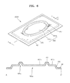
- FIGS. 4 through 8 are perspective views illustrating various shapes of the complex member 180A of FIG. 1 .
- a complex member 280A includes a base unit 281, a convex portion 285 that protrudes from the base unit 281 to a predetermined height, and an inclination unit 283 connecting the base unit 281 and the convex portion 285.
- the complex member 280A has a first surface facing the substrate 110 and a second surface opposite to the first surface. A first surface of the base unit 281 contacts the sealing unit 150.
- the convex portion 285 is rectangular and protrudes upward from the base unit 281 in a direction away from the substrate 110. Thus a total height and a surface area of the complex member 280A are increased.
- a concave portion 289 is formed inside the complex member 280A due to the convex portion 285.
- a metal layer 170 is formed under the complex member 280A.
- a complex member 380A includes a base unit 381, a convex portion 385 that protrudes from the base unit 381 to a predetermined height, and an inclination unit 383 connecting the base unit 381 and the convex portion 385.
- the complex member 380A has a first surface facing the substrate 110 and a second surface opposite to the first surface.
- the base unit 381 includes a first region 381 a whose first surface contacts the sealing unit 150 and a second region 381 b having a rectangular shape with four curved corners.
- the convex portion 385 borders the first region 381 a and the second region 381 b.
- the convex portion 385 has a shape of a rectangular ring.
- the convex portion 385 protrudes upward from the base unit 381 in a direction away from the substrate 110, and thus a total height of the complex member 380A is increased.
- a concave portion 389 having a rectangular ring shape is formed inside the complex member 380A due to the convex portion 385.
- a metal layer 170 is disposed under the complex member 380A.
- a getter may be further disposed in the concave portion 389.
- a complex member 480A includes a base unit 481, a first convex portion 485 that protrudes from the base unit 481 to a predetermined height, an inclination unit 483 connecting the base unit 481 and the first convex portion 485, and a second convex portion 487 that protrudes from the first convex portion 485 to another predetermined height.
- the complex member 480A has a first surface facing the substrate 110 and a second surface opposite to the first surface.
- a first surface of the base unit 481 contacts the sealing unit 150.
- the first convex portion 485 has a shape of a rectangular plate.
- the first convex portion 485 includes a first region 485a and a second region 485b, the second region 485b having an oval shape.
- the second convex portion 487 borders the first region 485a and the second region 485b.
- the second convex portion 487 has a shape of an oval ring, and protrudes upward from the first convex portion 485.
- the first convex portion 485 and the second convex portion 487 sequentially protrude upward from the base unit 481 in a direction away from the substrate 110.
- a total height and surface area of the complex member 480A are increased.
- a rectangular concave portion 489a is formed inside the complex member 480A due to the first convex portion 485.
- An oval-shaped concave portion 489b is further formed in the rectangular concave portion 489a due to the second convex portion 487.
- a metal layer 170 is disposed under the complex member 480A.
- a getter may be further disposed in the concave portions 489a and 489b.
- a complex member 580A includes a base unit 581 and a first convex portion 585 that protrudes from the base unit 581 to a predetermined height.
- the complex member 580A also includes an inclination unit 583 connecting the base unit 581 and the first convex portion 585, and a second convex portion 587 that protrudes from the first convex portion 585 to another predetermined height.
- the complex member 580A has a first surface facing the substrate 110 and a second surface opposite to the first surface.
- a first surface of the base unit 581 contacts the sealing unit 150.
- the first convex portion 585 has a shape of a rectangular plate.
- the second convex portion 587 protrudes upward from the first convex portion 585.
- the second convex portion 587 has an X-shape such that lines of the X-shape extend in a diagonal direction across the complex member 580A.
- the second convex portion 587 is formed of a center portion 587e and ribs 587a, 587b, 587c, and 587d, each having a stripe shape extending from the center portion 587e.
- the first convex portion 585 and the second convex portion 587 sequentially protrude upward from the base unit 581 in a direction away from the substrate 110. As such, a total height and surface area of the complex member 580A are increased.
- a rectangular concave portion 589a is formed inside the complex member 580A by the first convex portion 585.
- An X-shaped concave portion 589b is further formed in the rectangular concave portion 589a due to the second convex portion 587.
- a metal layer 170 is formed under the complex member 580A.
- a getter may be further disposed in the concave portions 589a and 589b.
- the complex member 680A includes a base unit 681 and a first convex portion 685 that protrudes from the base unit 681 to a predetermined height.
- the complex member 680A also includes an inclination unit 683 connecting the base unit 681 and the first convex portion 685, and a second convex portion 687 that protrudes from the first convex portion 685 to another predetermined height.
- the complex member 680A has a first surface facing the substrate 110 and a second surface opposite to the first surface. A first surface of the base unit 681 contacts the sealing unit 150.
- the first convex portion 685 has a shape of a rectangular plate.
- the second convex portion 687 is formed of at least one rib. As shown in FIG. 8 , the second convex portion 687 is formed of ribs 687a, 687b, 687c, 687d, and 687e, which each have a stripe shape and are arranged to be parallel. In the current embodiment, five ribs are illustrated in FIG. 8 . However, aspects of the present invention are not limited thereto, and the second convex portion 687 may have any suitable number of ribs in a variety of suitable patterns.
- the first convex portion 685 and the second convex portion 687 sequentially protrude upward from the base unit 681 in a direction away from the substrate 110.
- a total height of the complex member 680A is increased.
- a rectangular concave portion 689a is formed in the complex member 680A due to the first convex portion 685.
- Concave portions 689b, each having a stripe shape, are further formed in the rectangular concave portion 689a due to the ribs 687a through 687e formed in the second convex portion 687.
- a metal layer 170 is disposed under the complex member 680A.
- a getter may be further disposed in the concave portions 689a and 689b.
- FIG. 9 is a cross-sectional view illustrating a display apparatus 100B according to another embodiment of the present invention.
- the display apparatus 100B includes a substrate 110, a display unit 130, an encapsulation unit 190B, and a sealing unit 150.
- the display apparatus 100B of FIG. 9 is generally the same as the display apparatus 100A of FIG. 1 , except for a shape of a complex member 180B. Thus, descriptions of repeated components will be omitted below.
- the encapsulation unit 190B is disposed so as to face the display unit 130.
- the encapsulation unit 190B protects the display unit 130 from water, oxygen and other foreign materials coming from outside of the display apparatus 100B.
- the encapsulation unit 190B includes a metal layer 170 and a complex member 180B.
- the complex member 180B is formed on the metal layer 170. That is, the complex member 180B is disposed further away from the display unit 130 than the metal layer 170 is.
- the complex member 180B includes a resin matrix and carbon fibers as illustrated in FIGS. 2 and 3 .
- a shape of the encapsulation unit 190B is determined by a shape of the complex member 180B.
- the complex member 180B is molded as a hot plate by using a mold.
- the encapsulation unit 190B includes a convex portion 185 separated from the display unit 130.
- a total height and surface area of the encapsulation unit 190B are increased. Accordingly, by increasing a surface moment of inertia by increasing the total height of the encapsulation unit 190B, rigidity of the encapsulation unit 190B is increased without increasing the thickness or weight of the encapsulation unit 190B. By increasing a rigidity of the encapsulation unit 190B, bending of the encapsulation unit 190B may be prevented.
- the encapsulation unit 190B may further include a protrusion 160 formed in an area of an upper surface of the encapsulation unit 190B.
- the protrusion 160 is a connection member connecting an external device (not shown), such as a printed circuit board (PCB), to the display apparatus 100B.
- the protrusion 160 may have a bolt shape having a threaded outer surface, or other suitable shapes.
- the protrusion 160 is formed as a single unit with the complex member 180B of the encapsulation unit 190B and as an uppermost layer of the complex member 180B. Positions, heights of the protrusion 160 and the number of protrusions 160 are determined according to a type of external devices to be connected to the display apparatus 100B. However, aspects of the present invention are not limited thereto, and the protrusion 160 may be formed to not be a single unit with the complex member 180B and the position, height and number of protrusions 160 may be determined according to other suitable requirements.
- FIGS. 10 through 15 are perspective views illustrating various shapes of the complex member 180B of FIG. 9 .
- perspective views of the complex member 180B are illustrated, and in lower portions of FIGS. 10 through 15 , cross-sectional views of the complex member 180B taken along a line A-A' in FIGS. 10-15 and a line B-B' in FIGS. 13-15 of the above perspective views are illustrated.
- a complex member 280B includes a base unit 281, a convex portion 285 that protrudes from the base unit 281 to a predetermined height, and an inclination unit 283 connecting the base unit 281 and the convex portion 285.
- the complex member 280B has a first surface facing the substrate 110 and a second surface opposite to the first surface. A first surface of the base unit 281 contacts the sealing unit 150.
- At least one protrusion 260 is formed on an upper surface of the convex portion 285 to connect to an external device (not shown).
- the convex portion 285 protrudes upward from the base unit 281 in a direction away from the substrate 110, and thus a total height and surface area of the complex member 280B are increased.
- a concave portion 289 is formed in the complex member 280B due to the convex portion 285.
- a metal layer 170 is disposed under the complex member 280B.
- a getter may be further disposed in the concave portion 289.
- a complex member 380B includes a base unit 381, a convex portion 385 that protrudes from the base unit 381 to a predetermined height, and an inclination unit 383 connecting the base unit 381 and the convex portion 385.
- the complex member 380B has a first surface facing the substrate 110 and a second surface opposite to the first surface.
- the base unit 381 includes a first region 381 a whose first surface contacts the sealing unit 150 and a second region 381 b having a rectangular shape with four curved corners. The first region 381 a and the second region 381 b are bordered by the convex portion 385.
- At least one protrusion 360 is formed in the second region 381 b of the base unit 381 to connect to an external device (not shown).
- the convex portion 385 has a shape of a rectangular ring.
- the convex portion 385 protrudes upward from the base unit 381 in a direction away from the substrate 110, and thus the total height of the complex member 380B is increased.
- a concave portion 389 having a rectangular ring shape is formed inside the complex member 380B due to the convex portion 385.
- a metal layer 170 is disposed under the complex member 380B. Although not required in all aspects of the present invention, a getter may be further disposed in the concave portion 389.
- a complex member 480B includes a base unit 481, a first convex portion 485 that protrudes from the base unit 481 to a predetermined height, an inclination unit 483 connecting the base unit 481 and the first convex portion 485, and a second convex portion 487 that protrudes from the first convex portion 485 to another predetermined height.
- the complex member 480B has a first surface facing the substrate 110 and a second surface opposite to the first surface. A first surface of the base unit 481 contacts the sealing unit 150.
- the first convex portion 485 has a shape of a rectangular plate.
- the first convex portion 485 includes a first region 485a and a second region 485b, the second region 485b having an oval shape.
- the first region 485a and the second region 485b are bordered by the second convex portion 487.
- At least one protrusion 460 is formed in the second region 485b of the first convex portion 485 to connect to an external device (not shown).
- the second convex portion 487 has an oval ring shape, and protrudes upward from the first convex portion 485.
- the first convex portion 485 and the second convex portion 487 sequentially protrude upward from the base unit 481 in a direction away from the substrate 110.
- a total height and surface area of the complex member 480B are increased.
- a rectangular concave portion 489a is formed inside the complex member 480B due to the first convex portion 485.
- An oval-shaped concave portion 489b is further formed in the rectangular concave portion 489a due to the second convex portion 487.
- a metal layer 170 is disposed under the complex member 480B.
- a getter may be further disposed in the concave portions 489a and 489b.
- a complex member 580B includes a base unit 581 and a first convex portion 585 that protrudes from the base unit 581 to a predetermined height.
- the complex member 580B also includes an inclination unit 583 connecting the base unit 581 and the first convex portion 585, and a second convex portion 587 that protrudes from the first convex portion 585 to another predetermined height.
- the complex member 580B has a first surface facing the substrate 110 and a second surface opposite to the first surface. A first surface of the base unit 581 contacts the sealing unit 150.
- the first convex portion 585 has a shape of a rectangular plate.
- the second convex portion 587 protrudes upward from the first convex portion 585.
- the second convex portion 587 has an X-shape, such that lines of the X-shape extend in diagonal directions of the complex member 580B.
- the second convex portion 587 is formed of a center portion 587e and ribs 587a, 587b, 587c, and 587d.
- the ribs 587a to 587d each have a stripe shape that branches from the center portion 587e.
- At least one protrusion 560 is formed between two adjacent ones of the ribs 587a, 587b, 587c, and 587d to connect to an external device (not shown).
- a total height and surface area of the complex member 580B are increased.
- a rectangular concave portion 589a is formed inside the complex member 580B due to the first convex portion 585.
- An X-shaped concave portion 589b is further formed in the rectangular concave portion 589a by the second convex portion 587.
- a metal layer 170 is formed under the complex member 580B.
- complex members 680B and 680B' each include a base unit 681 and a first convex portion 685 that protrudes from the base unit 681 to a predetermined height.
- the complex members 680B and 680B' also include an inclination unit 683 connecting the base unit 681 and the first convex portion 685, and a second convex portion 687 that protrudes from the first convex portion 685 to another predetermined height.
- Each of the complex members 680B and 680B' has a first surface facing the substrate 110 and a second surface opposite to the first surface. A first surface of the base unit 681 contacts the sealing unit 150.
- the first convex portion 685 has a shape of a rectangular plate.
- the second convex portion 687 is formed of at least one rib. As shown in FIGS. 14 and 15 , ribs 687a, 687b, 687c, 687d, and 687e have a stripe shape and are arranged to be parallel to each other. According to the present embodiment, five ribs are illustrated in FIGS. 14 and 15 , however, aspects of the present invention are not limited thereto and the second convex portion 687 may be formed of other suitable numbers of ribs.
- At least one protrusion 660a is formed on the at least one of the ribs 687a, 687b, 687c, 687d, and 687e to connect to an external device (not shown).
- at least one protrusion 660b is formed between at least two of the ribs 687a, 687b, 687c, 687d, and 687e formed on the first convex portion 685 to connect to an external device (not shown).
- the protrusions 660a are formed on some of the ribs 687a to 687e
- the protrusions 660b are formed between some of the ribs 687a to 687e.
- a total height and surface area of the complex member 680B are increased.
- a rectangular concave portion 689a is formed inside the complex member 680B due to the first convex portion 685.
- Concave portions 689b, each having a stripe shape, are further formed in the rectangular concave portion 689a due to the ribs 687a through 687e formed in the second convex portion 687.
- a metal layer 170 is formed under the complex member 680B.
- a getter may be further disposed in the concave portions 689a and 689b.
- FIG. 16 is a cross-sectional view illustrating a display apparatus 100C according to another embodiment of the present invention.
- FIGS. 17 through 21 are perspective views illustrating various shapes of the complex member of FIG. 16 .
- the display apparatus 100C includes a substrate 110, a display unit 130, an encapsulation unit 190C, and a sealing unit 150.
- the display apparatus 100C of FIG. 16 is generally the same as the display apparatus 100A of FIG. 1 .
- a shape of a complex member 180C is different from the shape of the complex member 180A of the display apparatus 100A of FIG. 1 .
- description of repeated components will be omitted below.
- the encapsulation unit 190C is disposed to face the display unit 130.
- the encapsulation unit 190C includes a metal layer 170 and the complex member 180C.
- the complex member 180C is formed on the metal layer 170. That is, the complex member 180C is disposed farther away from the display unit 130 than the metal layer 170 is.
- the complex member 180C includes a resin matrix and carbon fibers as illustrated in FIGS. 2 and 3 .
- a shape of the encapsulation unit 190C is determined by a shape of the complex member 180C.
- the complex member 180C is molded as a hot plate by using a mold.
- aspects of the present invention are not limited thereto and the complex member 180C may be formed using other suitable methods.
- the encapsulation unit 190C includes a convex portion 185 extending in a direction away from the display unit 130 to thereby increase the height and surface area of the encapsulation unit 190C. Accordingly, a surface moment of inertia is increased by increasing a total height of the encapsulation unit 190C without increasing a thickness or weight of the encapsulation unit 190C.
- a rigidity of the encapsulation unit 190C is increased so as to prevent bending.
- a concave portion 189 is formed in the encapsulation unit 190C due to the convex portion. Thus, even when a getter is formed in the concave portion 189, contact between the encapsulation unit 190C and the display unit 130 may be prevented.
- the complex member 180C of the encapsulation unit 190C may have various shapes as illustrated in FIGS. 4 through 8 . Also, the complex member 180C may include a protrusion (not shown) formed in an area of an upper surface of the complex member 180C to connect to an external device, as illustrated in FIGS. 10 through 15 .
- the complex member 180C includes an extension portion 140 that extends from an edge of the complex member 180C along the substrate 110 in a vertical direction in order to protect the substrate 110.
- the extension portion 140 is formed as a single unit with the complex member 180C.
- the extension portion 140 is formed to surround edges of the substrate 110 to prevent the edge from colliding with other objects. Accordingly, the encapsulation unit 190C ensures increased rigidity but also a durable structure with respect to handling or dynamic impact.
- the complex member 180C has various shapes as shown by complex members 280C, 380C, 480C, 580C, and 680C illustrated in FIGS. 17 through 21 .
- the complex members 280C, 380C, 480C, 580C, and 680C respectively include extension portions 240, 340, 440, 540, and 640 extending from edges thereof along the substrate 110 in a vertical direction.
- the extension portions 140 to 640 are formed to surround all edges of the substrate 110. Additionally, a portion of each of the extension portions 140 to 640 is formed to be opened as illustrated in FIGS. 17 through 21 .
- the extension portions 140 to 640 are formed to cover circuit wiring that extends out of the substrate 110. Alternatively, the open portion of each of the extension portions 140 to 640 is disposed in a manner corresponding to the circuit wiring to increase convenience of assembly during an assembling process.
- FIGS. 17 through 21 Other components of the display apparatus 100C illustrated in FIGS. 17 through 21 are the same as those in FIGS. 4 through 8 and FIGS. 10 through 15 , and thus descriptions thereof will be omitted below.
- FIG. 22 is a cross-sectional view illustrating a display apparatus 100D according to another embodiment of the present invention.
- FIGS. 23 and 24 are perspective views illustrating various shapes of a complex member 180D of FIG. 22 .
- the display apparatus 100D includes a substrate 110, a display unit 130, an encapsulation unit 190D, and a sealing unit 150.
- the display apparatus 100D of FIG. 22 is generally the same as the display apparatus 100A of FIG. 1 except that a shape of an encapsulation unit 190D is different from a shape of the encapsulation unit 190A of the display apparatus 100A of FIG. 1 .
- descriptions of repeated components will be omitted below.
- the encapsulation unit 190D is disposed so as to face the display unit 130.
- the encapsulation unit 190D includes a metal layer 170 and the complex member 180D.
- the complex member 180D is formed on the metal layer 170. That is, the complex member 180D is disposed farther away from the display unit 130 than the metal layer 170 is.
- the complex member 180D includes a resin matrix and a plurality of carbon fibers, as illustrated in FIGS. 2 and 3 .
- the complex member 180D is flat, and a rib 120 protrudes in a form of a wallboard along a lengthwise direction from an upper surface of the complex member 180D.
- the rib 120 includes ribs 120a and 120d at two opposing edges of the rib 120 and extending along the lengthwise direction of the complex member 180D. Ribs 120b and 120c are formed interior to the ribs 120a and 120d on the complex member 180D. The ribs 120b and 120c are parallel to the ribs 120a and 120d.
- the rib 120 is formed as a single body with the complex member 180D and is extended therefrom.
- the rib 120 increases a surface moment of inertia of a cross-section of the complex member 180D in order to reduce drooping or twist distortion.
- the complex member 180D is formed using a pultrusion method, and thus may be manufactured at reduced cost compared to a manufacturing method which uses the above-described mold.
- aspects of the present invention are not limited to the above, and the complex member 180D may be formed using other suitable methods.
- protrusions 125 are formed on a portion of the upper surface of the complex member 180D.
- the protrusions 125 are a connection member that connects an external device (not shown), such as a PCB, to the display apparatus 100D.
- the protrusions 125 may have a bolt shape having a threaded outer surface.
- the protrusions 125 are each formed as a single unit with the complex member 180D of the encapsulation unit 190D and are each formed as a single unit with an uppermost layer of the complex member 180B. Positions or a number of the protrusions 125 are determined according to a type of the external devices to be connected to the display apparatus 100D.
- a separate protrusion 125 for example, a bolt-shaped connection member, may be inserted into a predetermined position of the complex member 180D before the complex member 180D is crystallized, and then be fixed by hardening the complex member 180D.
- the complex member 180D may include an extension portion that is extended from an edge of the complex member 180D along the substrate 110 in a vertical direction.
- the extension portion protects the substrate 110 as illustrated in FIGS. 17 through 21 .
- the extension portion is formed as a single unit with the complex member 180D.
- the extension portion is formed to surround an edge of the substrate 110 to prevent the edge of the substrate 110 from colliding with other objects. Accordingly, the encapsulation unit 190C obtains not only stably increased rigidity but also a durable structure with respect to handling or dynamic impact.
- the display apparatus includes an encapsulation unit including a thin and light-weight complex member and a metal layer formed as a single unit.
- a reinforcement member formed on an upper surface of the complex member, increases a surface moment of inertia of the complex member. Thus, rigidity of the encapsulation unit is increased.
- the reinforcement member may be convex portions formed on the base unit of the complex member as a single unit with the complex member or at least one rib formed on the upper surface of the complex member.
- the complex member has a three-dimensional shape and thus instrumental rigidity of the display apparatus may be increased. In other words, bending can be prevented, and rigidity and drop reliability may be increased.
- the display apparatus does not have to include a bezel for maintaining rigidity or an adhesive tape for adhering the bezel to the encapsulation unit.
- the convex portions are formed on the complex member so as to form a three-dimensional shape and form a concave portion in an inner portion of the complex member. Accordingly, a material such as a getter may be easily inserted between the encapsulation unit and a lower substrate.
- the edges of the complex member protrude toward the lower substrate, thereby stably increasing rigidity and protecting the edges of the lower substrate.
- additional components or connection portions connecting to the external device such as a PCB may be eliminated.
- the encapsulation unit is formed to have various shapes without increasing a thickness of the encapsulation unit to thereby increase a surface moment of inertia. Accordingly, a light-weight and slim display apparatus with increased rigidity can be manufactured at low cost.
Landscapes
- Engineering & Computer Science (AREA)
- Physics & Mathematics (AREA)
- General Physics & Mathematics (AREA)
- Theoretical Computer Science (AREA)
- Multimedia (AREA)
- Signal Processing (AREA)
- Chemical & Material Sciences (AREA)
- Crystallography & Structural Chemistry (AREA)
- Devices For Indicating Variable Information By Combining Individual Elements (AREA)
- Electroluminescent Light Sources (AREA)
- Cathode-Ray Tubes And Fluorescent Screens For Display (AREA)
- Liquid Crystal (AREA)
Abstract
Description
- Aspects of the present invention relate to display apparatuses, and more particularly, to display apparatuses including an encapsulation unit having improved rigidity.
- Recently, display apparatuses are being replaced with portable, thin flat display apparatuses. In particular, flat display apparatuses, such as organic light emitting display apparatuses and liquid crystal display apparatuses, have a high image quality and thus are gaining attention. A flat display apparatus includes a display unit on a lower substrate and an encapsulation substrate disposed on the display unit to protect the display unit. Also, the sealing unit is disposed between the lower substrate and the encapsulation substrate.
- However, the flat display apparatus is easily deformed or damaged by heat. To prevent this damage, a thick lower substrate or a thick encapsulation substrate may be formed. However, in this case, if an external force due to thermal residual stress of the sealing unit is applied to the flat display apparatus, a rigidity of the display apparatus may be greatly weakened and disbanding may occur along the sealing unit due to a peel stress.
- Aspects of the present invention provide display apparatuses including an encapsulation unit having an improved structure for increasing the rigidity of the encapsulation unit by using a reinforcement member.
- According to an aspect of the present invention, there is provided a display apparatus including a display unit disposed on a substrate; an encapsulation facing the display unit including: a metal layer; and a complex member, including a base unit and a convex portion that protrudes upward from the base unit. The display apparatus may further include a sealing unit disposed between the substrate and the encapsulation unit and apart from the display unit, the sealing unit bonding the substrate and the encapsulation unit to the sealing unit. The sealing unit may comprise an epoxy resin.
- According to another aspect of the present invention the convex portion may extend from the base unit in a direction away from the substrate and wherein the convex portion has a shape of a rectangular plate. In particular, the convex portion may have a shape of a square plate.
- According to another aspect of the present invention the convex portion may have a shape of a rectangular ring. In particular, the convex portion may have a shape of a square ring.
- According to another aspect of the present invention the convex portion may comprise: a first convex portion extending from the base unit in a direction away from the substrate and having a shape of a rectangular plate; and a second convex portion having a shape of an oval ring, an X-shape, or a stripe shape, and protruding upward from the first convex portion. In particular, the first convex portion may have a shape of a square plate.
- According to another aspect of the present invention the convex portion may further comprise a protrusion protruding from an upper surface.
- According to another aspect of the present invention the convex portion may further comprise an extension portion extending from an edge of the encapsulation unit and surrounding an edge of the substrate.
- According to another aspect of the present invention the complex member may include a resin matrix and carbon fibers, wherein the metal layer is disposed nearer to the substrate than the complex member is. The carbon fibers may comprise first carbon fibers arranged in a first direction and second carbon fibers arranged in a second direction crossing the first direction. The carbon fibers may be woven by being arranged in a horizontal direction and a vertical direction. Preferably a thermal expansion rate of the carbon fibers is smaller than a thermal expansion rate of the substrate. The complex member may be formed of layers each including the resin matrix and the carbon fibers. Preferably, some of the carbon fibers are arranged in at least one of the layers in a first direction, and others of the carbon fibers are arranged in another layer of the layers in a second direction, and the first direction and the second direction cross each other. The first direction and second direction may cross each other at right angles; that is, the second direction may be perpendicular to the second direction.
- According to another aspect of the present invention, there is provided a display apparatus including: a display unit disposed on a substrate; an encapsulation unit facing the display unit, the encapsulation unit including: a metal layer; a complex member; and at least one rib formed on an upper surface of the complex member; and a sealing unit disposed between the substrate and the encapsulation unit and apart from the display unit to bond the substrate and the encapsulation unit to the sealing unit.
- According to another aspect of the present invention the rib may extend in a lengthwise direction of the complex member.
- According to another aspect of the present invention the complex member may include a protrusion protruding from an upper surface.
- According to another aspect of the present invention the complex member may include an extension portion extending from an edge of the encapsulation unit to surround an edge of the substrate.
- According to another aspect of the present invention the complex member may include: a resin matrix; and carbon fibers, wherein the metal layer is disposed nearer to the substrate than the complex member is.
- According to another aspect of the present invention, there is provided a display apparatus including: a display unit disposed on a substrate; an encapsulation unit facing the display unit, the encapsulation unit comprising: a metal layer; a complex member; and a reinforcement member formed on an upper surface of the complex member; and a sealing unit disposed apart from the display unit between the substrate and the encapsulation unit to bond the substrate and the encapsulation unit to the sealing unit.
- According to another aspect of the present invention the reinforcement member may be a convex portion protruding upwards from a base unit of the complex member, and wherein the reinforcement member is formed as a single unit with the complex member.
- According to another aspect of the present invention the reinforcement member may be at least one rib that is formed on an upper surface of the complex member.
- Additional aspects and/or advantages of the invention will be set forth in part in the description which follows and, in part, will be obvious from the description, or may be learned by practice of the invention.
- These and/or other aspects and advantages of the invention will become apparent and more readily appreciated from the following description of the embodiments, taken in conjunction with the accompanying drawings of which:
-
FIG. 1 is a cross-sectional view of a display apparatus according to an embodiment of the present invention; -
FIGS. 2 and3 are schematic views illustrating a complex member illustrated inFIG. 1 ; -
FIGS. 4 through 8 are perspective views illustrating various shapes of the complex member ofFIG. 1 ; -
FIG. 9 is a cross-sectional view illustrating a display apparatus according to another embodiment of the present invention; -
FIGS. 10 through 15 are perspective views illustrating various shapes of a complex member ofFIG. 9 ; -
FIG. 16 is a cross-sectional view illustrating a display apparatus according to another embodiment of the present invention; -
FIGS. 17 through 21 are perspective views illustrating various shapes of a complex member ofFIG. 16 ; -
FIG. 22 is a cross-sectional view illustrating a display apparatus according to another embodiment of the present invention; and -
FIGS. 23 and24 are perspective views illustrating a complex member ofFIG. 22 . - Reference will now be made in detail to the present embodiments of the present invention, examples of which are illustrated in the accompanying drawings, wherein like reference numerals refer to the like elements throughout. The embodiments are described below in order to explain the present invention by referring to the figures.
-
FIG. 1 is a cross-sectional view of adisplay apparatus 100A, according to an embodiment of the present invention.FIGS. 2 and3 are schematic views illustrating acomplex member 180A illustrated inFIG. 1 . Referring toFIG. 1 , thedisplay apparatus 100A includes asubstrate 110, adisplay unit 130, anencapsulation unit 190A, and asealing unit 150. - The
substrate 110 is formed of a transparent glass having SiO2 as a main component. However, aspects of the present invention are not limited thereto and may also be formed of other transparent plastic materials. Examples of the plastic material of thesubstrate 110 include polyethersulphone (PES), polyacrylate (PAR), polyetherimide (PEI), polyethyelenen napthalate (PEN), polyethyeleneterepthalate (PET), polyphenylene sulfide (PPS), polyallylate, polyimide, poly carbonate (PC), cellulose triacetate (TAC), cellulose acetate propionate (CAP), and other similar materials. - A plurality of processes are performed to form the
display unit 130 on thesubstrate 110, and heat is applied during these processes, which causes thesubstrate 110 to expand. The expansion of thesubstrate 110 reduces durability of thedisplay apparatus 100A and precision of thedisplay unit 130. Accordingly, thesubstrate 110 has a low thermal expansion rate, for example, 3*10-6/K to 4*10-6/K. Thedisplay unit 130 comprises an organic light emitting device, a liquid crystal display apparatus, etc., and is disposed on thesubstrate 110. - The
encapsulation unit 190A is disposed so as to face thedisplay unit 130. Theencapsulation unit 190A protects thedisplay unit 130 from water or oxygen, or other similar impurities or elements, from the outside. Theencapsulation unit 190A includes ametal layer 170 and acomplex member 180A. Thecomplex member 180A is formed on themetal layer 170. That is, thecomplex member 180A is disposed farther from thedisplay unit 130 than themetal layer 170 is. - The sealing
unit 150 is hardened by heat to bond both thesubstrate 110 and theencapsulation unit 190A to thesealing unit 150. Theencapsulation unit 190A may expand while heat is applied to thesealing unit 150. If the degree to which theencapsulation unit 190A is expanded by the heat is increased, a bonding force between thesubstrate 110 and theencapsulation unit 190A is reduced. In such a case, the durability of thedisplay apparatus 100A may weaken. - However, according to the present embodiment of the present invention, the
encapsulation unit 190A includes thecomplex member 180A having a low thermal expansion rate and thus is not greatly expanded. Thecomplex member 180A has a thermal expansion rate that is lower than or similar to that of thesubstrate 110. Thecomplex member 180A may include, as illustrated inFIGS. 2 and3 , a resin matrix and a plurality of carbon fibers. - Referring to
FIG. 2 , thecomplex member 180A may include aresin matrix 181 and a plurality ofcarbon fibers 182. - The
complex member 180A is formed of thecarbon fibers 182 impregnated in theresin matrix 181. Thecarbon fibers 182 are arranged to cross one another in rows and columns. That is, thecarbon fibers 182 include carbon fibers arranged in an X-axis direction ofFIG. 2 andcarbon fibers 182 arranged in a Y-axis direction ofFIG. 2 . Accordingly, thecomplex member 180A having a uniform and low thermal expansion rate over the entire area may be formed. InFIG. 2 , thecarbon fibers 182 are arranged perpendicularly across one another. However, aspects of the present invention are not limited thereto, and an angle at which thecarbon fibers 182 are arranged across one another may be determined such that thecomplex member 180A has a desired thermal expansion rate. - Also, the
carbon fibers 182 are woven in a latitudinal and longitudinal direction. Thecarbon fibers 182 arranged in the X-axis direction ofFIG. 2 and thecarbon fibers 182 arranged in the Y-axis direction ofFIG. 2 may be woven as a fabric. Consequently, a durability of thecomplex member 180A is increased. - The
carbon fibers 182 have a lower thermal expansion rate than thesubstrate 110. In particular, the thermal expansion rate of thecarbon fibers 182 in a lengthwise direction is a negative (-) value. Thecarbon fibers 182 do not absorb moisture, thus increasing the ability of theencapsulation unit 190A to prevent water penetration. - The
resin matrix 181 has a thermal expansion rate of 15*10-6/K to 120*10-6/K. Thecomplex member 180A having a predetermined thermal expansion rate is formed by mixing thecarbon fibers 182 and theresin matrix 181. That is, thecomplex member 180A having a thermal expansion rate lower than or a similar to a thermal expansion rate of thesubstrate 110 is formed. Thecomplex member 180A is controlled to have the predetermined thermal expansion rate by adjusting an amount of thecarbon fibers 182 and an amount of theresin matrix 181. - Referring to
FIG. 3 , according to another embodiment of the present invention, thecomplex member 180A includes layers, and each of the layers includes a resin matrix and carbon fibers. Also, each of the layers is formed of carbon fibers impregnated in the resin matrix. Each layer of thecomplex member 180A is formed to have carbon fibers arranged in a predetermined direction, and the layers are stacked on top of each other. Accordingly, thecomplex member 180A having the carbon fibers arranged to thereby cross one another is easily formed. Thecomplex member 180A includes afirst layer 183A, asecond layer 183B, athird layer 183C, and afourth layer 183D. Each of the first throughfourth layers 183A to 183D respectively includes aresin matrix carbon fibers - A direction of the
carbon fibers first layer 183A and thefourth layer 183D is disposed so as to cross a direction of thecarbon fibers second layer 183B and thethird layer 183C. In detail, thecarbon fibers first layer 183A and thefourth layer 183D are arranged in a first direction (Y-axis direction ofFIG. 3 ), and thecarbon fibers second layer 183B and thethird layer 183C are arranged in a second direction (X-axis direction ofFIG. 3 ). The first direction and the second direction cross each other so as to be perpendicular to each other, as shown inFIG. 3 . However, aspects of the present invention are not limited thereto and the first direction and the second direction may cross each other at other suitable angles. For example, in order to adjust a desired thermal expansion rate of thecomplex member 180A, thecarbon fibers first layer 183A and thefourth layer 183D and thecarbon fibers second layer 183B and thethird layer 183C may be arranged at various angles. - Referring to
FIG. 1 , a shape of theencapsulation unit 190A is determined by a shape of thecomplex member 180A. Thus, thecomplex member 180A is molded as a hot plate by using a mold. Aconvex portion 185 of theencapsulation unit 190A that protrudes in a direction away from thedisplay unit 130 is formed as a single unit with thecomplex member 180A and themetal layer 170. Theconvex portion 185 increases a height and a surface area of thecomplex member 180A. Accordingly, by increasing a total height and the surface area of theencapsulation unit 190A without increasing a thickness and weight of theencapsulation unit 190A, a surface moment of inertia is increased so as to increase rigidity of theencapsulation unit 190A and to prevent bending. When a height of theencapsulation unit 190A is three times a thickness of a typical flat encapsulation unit, the surface moment of inertia is increased by about 27 times (3^3), and thus the rigidity of theencapsulation unit 190A is significantly increased. Accordingly, aconcave portion 189 is formed inside theencapsulation unit 190A due to the convex portion of theencapsulation unit 190A. Also, even when a getter used to absorb moisture inside theencapsulation unit 190A is inserted into theconcave portion 189, theencapsulation unit 190A and thedisplay unit 130 are prevented from contacting each other. The shape of thecomplex member 180A will be described later in detail with reference toFIGS. 4 through 8 . - The
metal layer 170 has a denser structure than thecomplex member 180A. Themetal layer 170 and thecomplex member 180A are used together to prevent water and foreign materials from penetrating thedisplay unit 130. Themetal layer 170 has a higher thermal expansion rate than thecomplex member 180A. Also, themetal layer 170 has a greater thermal expansion rate than thesubstrate 110. However, since theencapsulation unit 190A includes thecomplex member 180A, a total thermal expansion rate of theencapsulation unit 190A is low. In detail, by forming thecomplex member 180A to be thicker than themetal layer 170, the thermal expansion rate of theencapsulation unit 190A is effectively maintained low. - The sealing
unit 150 is disposed between thesubstrate 110 and theencapsulation unit 190A. The sealingunit 150 is formed around thedisplay unit 130. The sealingunit 150 bonds thesubstrate 110 and theencapsulation unit 190A to thesealing unit 150 and includes a thermosetting resin. In detail, the sealingunit 150 may include an epoxy resin. -
FIGS. 4 through 8 are perspective views illustrating various shapes of thecomplex member 180A ofFIG. 1 . In upper portions ofFIGS. 4 through 8 , perspective views of thecomplex member 180A are illustrated, and in lower portions ofFIGS. 4 through 8 , cross-sectional views of thecomplex member 180A taken along a line A-A' ofFIGS. 4 through 8 and a line B-B' ofFIGS. 7 and8 of the above perspective views are illustrated. Referring toFIG. 4 , acomplex member 280A includes abase unit 281, aconvex portion 285 that protrudes from thebase unit 281 to a predetermined height, and aninclination unit 283 connecting thebase unit 281 and theconvex portion 285. - The
complex member 280A has a first surface facing thesubstrate 110 and a second surface opposite to the first surface. A first surface of thebase unit 281 contacts thesealing unit 150. - The
convex portion 285 is rectangular and protrudes upward from thebase unit 281 in a direction away from thesubstrate 110. Thus a total height and a surface area of thecomplex member 280A are increased. Aconcave portion 289 is formed inside thecomplex member 280A due to theconvex portion 285. Ametal layer 170 is formed under thecomplex member 280A. Although aspects of the present invention are not limited to the following, a getter may be further disposed in theconcave portion 289. - Referring to
FIG. 5 , acomplex member 380A includes abase unit 381, aconvex portion 385 that protrudes from thebase unit 381 to a predetermined height, and aninclination unit 383 connecting thebase unit 381 and theconvex portion 385. Thecomplex member 380A has a first surface facing thesubstrate 110 and a second surface opposite to the first surface. Thebase unit 381 includes afirst region 381 a whose first surface contacts thesealing unit 150 and asecond region 381 b having a rectangular shape with four curved corners. Theconvex portion 385 borders thefirst region 381 a and thesecond region 381 b. - The
convex portion 385 has a shape of a rectangular ring. Theconvex portion 385 protrudes upward from thebase unit 381 in a direction away from thesubstrate 110, and thus a total height of thecomplex member 380A is increased. Aconcave portion 389 having a rectangular ring shape is formed inside thecomplex member 380A due to theconvex portion 385. Ametal layer 170 is disposed under thecomplex member 380A. Although not required in all aspects of the present invention, a getter may be further disposed in theconcave portion 389. - Referring to
FIG. 6 , acomplex member 480A includes abase unit 481, a firstconvex portion 485 that protrudes from thebase unit 481 to a predetermined height, aninclination unit 483 connecting thebase unit 481 and the firstconvex portion 485, and a secondconvex portion 487 that protrudes from the firstconvex portion 485 to another predetermined height. - The
complex member 480A has a first surface facing thesubstrate 110 and a second surface opposite to the first surface. A first surface of thebase unit 481 contacts thesealing unit 150. The firstconvex portion 485 has a shape of a rectangular plate. The firstconvex portion 485 includes afirst region 485a and asecond region 485b, thesecond region 485b having an oval shape. The secondconvex portion 487 borders thefirst region 485a and thesecond region 485b. - The second
convex portion 487 has a shape of an oval ring, and protrudes upward from the firstconvex portion 485. The firstconvex portion 485 and the secondconvex portion 487 sequentially protrude upward from thebase unit 481 in a direction away from thesubstrate 110. Thus, a total height and surface area of thecomplex member 480A are increased. A rectangularconcave portion 489a is formed inside thecomplex member 480A due to the firstconvex portion 485. An oval-shapedconcave portion 489b is further formed in the rectangularconcave portion 489a due to the secondconvex portion 487. Ametal layer 170 is disposed under thecomplex member 480A. Although aspects of the present invention are not limited thereto, a getter may be further disposed in theconcave portions - Referring to
FIG. 7 , acomplex member 580A includes abase unit 581 and a firstconvex portion 585 that protrudes from thebase unit 581 to a predetermined height. Thecomplex member 580A also includes aninclination unit 583 connecting thebase unit 581 and the firstconvex portion 585, and a secondconvex portion 587 that protrudes from the firstconvex portion 585 to another predetermined height. - The
complex member 580A has a first surface facing thesubstrate 110 and a second surface opposite to the first surface. A first surface of thebase unit 581 contacts thesealing unit 150. The firstconvex portion 585 has a shape of a rectangular plate. The secondconvex portion 587 protrudes upward from the firstconvex portion 585. The secondconvex portion 587 has an X-shape such that lines of the X-shape extend in a diagonal direction across thecomplex member 580A. The secondconvex portion 587 is formed of acenter portion 587e andribs center portion 587e. - The first
convex portion 585 and the secondconvex portion 587 sequentially protrude upward from thebase unit 581 in a direction away from thesubstrate 110. As such, a total height and surface area of thecomplex member 580A are increased. A rectangularconcave portion 589a is formed inside thecomplex member 580A by the firstconvex portion 585. An X-shapedconcave portion 589b is further formed in the rectangularconcave portion 589a due to the secondconvex portion 587. Ametal layer 170 is formed under thecomplex member 580A. Although aspects of the present invention are not limited thereto, a getter may be further disposed in theconcave portions - Referring to
FIG. 8 , thecomplex member 680A includes abase unit 681 and a firstconvex portion 685 that protrudes from thebase unit 681 to a predetermined height. Thecomplex member 680A also includes aninclination unit 683 connecting thebase unit 681 and the firstconvex portion 685, and a secondconvex portion 687 that protrudes from the firstconvex portion 685 to another predetermined height. Thecomplex member 680A has a first surface facing thesubstrate 110 and a second surface opposite to the first surface. A first surface of thebase unit 681 contacts thesealing unit 150. The firstconvex portion 685 has a shape of a rectangular plate. - The second
convex portion 687 is formed of at least one rib. As shown inFIG. 8 , the secondconvex portion 687 is formed ofribs FIG. 8 . However, aspects of the present invention are not limited thereto, and the secondconvex portion 687 may have any suitable number of ribs in a variety of suitable patterns. - The first
convex portion 685 and the secondconvex portion 687 sequentially protrude upward from thebase unit 681 in a direction away from thesubstrate 110. Thus a total height of thecomplex member 680A is increased. A rectangularconcave portion 689a is formed in thecomplex member 680A due to the firstconvex portion 685.Concave portions 689b, each having a stripe shape, are further formed in the rectangularconcave portion 689a due to theribs 687a through 687e formed in the secondconvex portion 687. Ametal layer 170 is disposed under thecomplex member 680A. Although aspects of the present invention are not limited thereto, a getter may be further disposed in theconcave portions -
FIG. 9 is a cross-sectional view illustrating adisplay apparatus 100B according to another embodiment of the present invention. Referring toFIG. 9 , thedisplay apparatus 100B includes asubstrate 110, adisplay unit 130, anencapsulation unit 190B, and asealing unit 150. Thedisplay apparatus 100B ofFIG. 9 is generally the same as thedisplay apparatus 100A ofFIG. 1 , except for a shape of acomplex member 180B. Thus, descriptions of repeated components will be omitted below. - The
encapsulation unit 190B is disposed so as to face thedisplay unit 130. Theencapsulation unit 190B protects thedisplay unit 130 from water, oxygen and other foreign materials coming from outside of thedisplay apparatus 100B. Theencapsulation unit 190B includes ametal layer 170 and acomplex member 180B. Thecomplex member 180B is formed on themetal layer 170. That is, thecomplex member 180B is disposed further away from thedisplay unit 130 than themetal layer 170 is. Thecomplex member 180B includes a resin matrix and carbon fibers as illustrated inFIGS. 2 and3 . - A shape of the
encapsulation unit 190B is determined by a shape of thecomplex member 180B. Thecomplex member 180B is molded as a hot plate by using a mold. Theencapsulation unit 190B includes aconvex portion 185 separated from thedisplay unit 130. Thus, a total height and surface area of theencapsulation unit 190B are increased. Accordingly, by increasing a surface moment of inertia by increasing the total height of theencapsulation unit 190B, rigidity of theencapsulation unit 190B is increased without increasing the thickness or weight of theencapsulation unit 190B. By increasing a rigidity of theencapsulation unit 190B, bending of theencapsulation unit 190B may be prevented. When a height of theencapsulation unit 190B is three times a thickness of a flat encapsulation unit, the surface moment of inertia is increased by about 27 times (3^3), and thus the rigidity of theencapsulation unit 190B is significantly increased. Accordingly, aconcave portion 189 is formed inside theencapsulation unit 190B due to the convex portion. Accordingly, when a getter is inserted into theconcave portion 189, theencapsulation unit 190B and thedisplay unit 130 are prevented from contacting each other. The shape of thecomplex member 180A will be described in detail with reference toFIGS. 10 through 15 . Theencapsulation unit 190B may further include aprotrusion 160 formed in an area of an upper surface of theencapsulation unit 190B. - The
protrusion 160 is a connection member connecting an external device (not shown), such as a printed circuit board (PCB), to thedisplay apparatus 100B. For example, theprotrusion 160 may have a bolt shape having a threaded outer surface, or other suitable shapes. Theprotrusion 160 is formed as a single unit with thecomplex member 180B of theencapsulation unit 190B and as an uppermost layer of thecomplex member 180B. Positions, heights of theprotrusion 160 and the number ofprotrusions 160 are determined according to a type of external devices to be connected to thedisplay apparatus 100B. However, aspects of the present invention are not limited thereto, and theprotrusion 160 may be formed to not be a single unit with thecomplex member 180B and the position, height and number ofprotrusions 160 may be determined according to other suitable requirements. -
FIGS. 10 through 15 are perspective views illustrating various shapes of thecomplex member 180B ofFIG. 9 . In upper portions ofFIGS. 10 through 15 , perspective views of thecomplex member 180B are illustrated, and in lower portions ofFIGS. 10 through 15 , cross-sectional views of thecomplex member 180B taken along a line A-A' inFIGS. 10-15 and a line B-B' inFIGS. 13-15 of the above perspective views are illustrated. - Referring to
FIG. 10 , acomplex member 280B includes abase unit 281, aconvex portion 285 that protrudes from thebase unit 281 to a predetermined height, and aninclination unit 283 connecting thebase unit 281 and theconvex portion 285. Thecomplex member 280B has a first surface facing thesubstrate 110 and a second surface opposite to the first surface. A first surface of thebase unit 281 contacts thesealing unit 150. - At least one
protrusion 260 is formed on an upper surface of theconvex portion 285 to connect to an external device (not shown). Theconvex portion 285 protrudes upward from thebase unit 281 in a direction away from thesubstrate 110, and thus a total height and surface area of thecomplex member 280B are increased. Aconcave portion 289 is formed in thecomplex member 280B due to theconvex portion 285. Ametal layer 170 is disposed under thecomplex member 280B. Although not required in all aspects of the present invention, a getter may be further disposed in theconcave portion 289. - Referring to
FIG. 11 , acomplex member 380B includes abase unit 381, aconvex portion 385 that protrudes from thebase unit 381 to a predetermined height, and aninclination unit 383 connecting thebase unit 381 and theconvex portion 385. Thecomplex member 380B has a first surface facing thesubstrate 110 and a second surface opposite to the first surface. Thebase unit 381 includes afirst region 381 a whose first surface contacts thesealing unit 150 and asecond region 381 b having a rectangular shape with four curved corners. Thefirst region 381 a and thesecond region 381 b are bordered by theconvex portion 385. - At least one
protrusion 360 is formed in thesecond region 381 b of thebase unit 381 to connect to an external device (not shown). Theconvex portion 385 has a shape of a rectangular ring. Theconvex portion 385 protrudes upward from thebase unit 381 in a direction away from thesubstrate 110, and thus the total height of thecomplex member 380B is increased. Aconcave portion 389 having a rectangular ring shape is formed inside thecomplex member 380B due to theconvex portion 385. Ametal layer 170 is disposed under thecomplex member 380B. Although not required in all aspects of the present invention, a getter may be further disposed in theconcave portion 389. - Referring to
FIG. 12 , acomplex member 480B includes abase unit 481, a firstconvex portion 485 that protrudes from thebase unit 481 to a predetermined height, aninclination unit 483 connecting thebase unit 481 and the firstconvex portion 485, and a secondconvex portion 487 that protrudes from the firstconvex portion 485 to another predetermined height. Thecomplex member 480B has a first surface facing thesubstrate 110 and a second surface opposite to the first surface. A first surface of thebase unit 481 contacts thesealing unit 150. - The first
convex portion 485 has a shape of a rectangular plate. The firstconvex portion 485 includes afirst region 485a and asecond region 485b, thesecond region 485b having an oval shape. Thefirst region 485a and thesecond region 485b are bordered by the secondconvex portion 487. At least oneprotrusion 460 is formed in thesecond region 485b of the firstconvex portion 485 to connect to an external device (not shown). The secondconvex portion 487 has an oval ring shape, and protrudes upward from the firstconvex portion 485. - The first
convex portion 485 and the secondconvex portion 487 sequentially protrude upward from thebase unit 481 in a direction away from thesubstrate 110. Thus, a total height and surface area of thecomplex member 480B are increased. A rectangularconcave portion 489a is formed inside thecomplex member 480B due to the firstconvex portion 485. An oval-shapedconcave portion 489b is further formed in the rectangularconcave portion 489a due to the secondconvex portion 487. Ametal layer 170 is disposed under thecomplex member 480B. Although not required in all aspects of the present invention, a getter may be further disposed in theconcave portions - Referring to
FIG. 13 , acomplex member 580B includes abase unit 581 and a firstconvex portion 585 that protrudes from thebase unit 581 to a predetermined height. Thecomplex member 580B also includes aninclination unit 583 connecting thebase unit 581 and the firstconvex portion 585, and a secondconvex portion 587 that protrudes from the firstconvex portion 585 to another predetermined height. Thecomplex member 580B has a first surface facing thesubstrate 110 and a second surface opposite to the first surface. A first surface of thebase unit 581 contacts thesealing unit 150. The firstconvex portion 585 has a shape of a rectangular plate. - The second
convex portion 587 protrudes upward from the firstconvex portion 585. The secondconvex portion 587 has an X-shape, such that lines of the X-shape extend in diagonal directions of thecomplex member 580B. The secondconvex portion 587 is formed of acenter portion 587e andribs ribs 587a to 587d each have a stripe shape that branches from thecenter portion 587e. At least oneprotrusion 560 is formed between two adjacent ones of theribs - As the first
convex portion 585 and the secondconvex portion 587 sequentially protrude upward from thebase unit 581 in a direction away from thesubstrate 110, a total height and surface area of thecomplex member 580B are increased. A rectangularconcave portion 589a is formed inside thecomplex member 580B due to the firstconvex portion 585. An X-shapedconcave portion 589b is further formed in the rectangularconcave portion 589a by the secondconvex portion 587. Ametal layer 170 is formed under thecomplex member 580B. Although not required in all aspects of the present invention, a getter may be further disposed in theconcave portions - Referring to
FIGS. 14 and15 ,complex members base unit 681 and a firstconvex portion 685 that protrudes from thebase unit 681 to a predetermined height. Thecomplex members inclination unit 683 connecting thebase unit 681 and the firstconvex portion 685, and a secondconvex portion 687 that protrudes from the firstconvex portion 685 to another predetermined height. Each of thecomplex members substrate 110 and a second surface opposite to the first surface. A first surface of thebase unit 681 contacts thesealing unit 150. The firstconvex portion 685 has a shape of a rectangular plate. - The second
convex portion 687 is formed of at least one rib. As shown inFIGS. 14 and15 ,ribs FIGS. 14 and15 , however, aspects of the present invention are not limited thereto and the secondconvex portion 687 may be formed of other suitable numbers of ribs. - As illustrated in
FIG. 14 , at least oneprotrusion 660a is formed on the at least one of theribs FIG. 15 , at least oneprotrusion 660b is formed between at least two of theribs convex portion 685 to connect to an external device (not shown). In other words, as shown inFIG. 14 , theprotrusions 660a are formed on some of theribs 687a to 687e, and as shown inFIG. 15 , theprotrusions 660b are formed between some of theribs 687a to 687e. - As the first
convex portion 685 and the secondconvex portion 687 sequentially protrude upward from thebase unit 681 in a direction away from thesubstrate 110, a total height and surface area of thecomplex member 680B are increased. A rectangularconcave portion 689a is formed inside thecomplex member 680B due to the firstconvex portion 685.Concave portions 689b, each having a stripe shape, are further formed in the rectangularconcave portion 689a due to theribs 687a through 687e formed in the secondconvex portion 687. Ametal layer 170 is formed under thecomplex member 680B. Although not required in all aspects of the present invention, a getter may be further disposed in theconcave portions -
FIG. 16 is a cross-sectional view illustrating adisplay apparatus 100C according to another embodiment of the present invention.FIGS. 17 through 21 are perspective views illustrating various shapes of the complex member ofFIG. 16 . Referring toFIG. 16 , thedisplay apparatus 100C includes asubstrate 110, adisplay unit 130, anencapsulation unit 190C, and asealing unit 150. Thedisplay apparatus 100C ofFIG. 16 is generally the same as thedisplay apparatus 100A ofFIG. 1 . However, a shape of acomplex member 180C is different from the shape of thecomplex member 180A of thedisplay apparatus 100A ofFIG. 1 . Thus, description of repeated components will be omitted below. - The
encapsulation unit 190C is disposed to face thedisplay unit 130. Theencapsulation unit 190C includes ametal layer 170 and thecomplex member 180C. Thecomplex member 180C is formed on themetal layer 170. That is, thecomplex member 180C is disposed farther away from thedisplay unit 130 than themetal layer 170 is. Thecomplex member 180C includes a resin matrix and carbon fibers as illustrated inFIGS. 2 and3 . - A shape of the
encapsulation unit 190C is determined by a shape of thecomplex member 180C. Thecomplex member 180C is molded as a hot plate by using a mold. However, aspects of the present invention are not limited thereto and thecomplex member 180C may be formed using other suitable methods. Theencapsulation unit 190C includes aconvex portion 185 extending in a direction away from thedisplay unit 130 to thereby increase the height and surface area of theencapsulation unit 190C. Accordingly, a surface moment of inertia is increased by increasing a total height of theencapsulation unit 190C without increasing a thickness or weight of theencapsulation unit 190C. Thus, a rigidity of theencapsulation unit 190C is increased so as to prevent bending. Aconcave portion 189 is formed in theencapsulation unit 190C due to the convex portion. Thus, even when a getter is formed in theconcave portion 189, contact between theencapsulation unit 190C and thedisplay unit 130 may be prevented. - The
complex member 180C of theencapsulation unit 190C may have various shapes as illustrated inFIGS. 4 through 8 . Also, thecomplex member 180C may include a protrusion (not shown) formed in an area of an upper surface of thecomplex member 180C to connect to an external device, as illustrated inFIGS. 10 through 15 . - The
complex member 180C includes anextension portion 140 that extends from an edge of thecomplex member 180C along thesubstrate 110 in a vertical direction in order to protect thesubstrate 110. Theextension portion 140 is formed as a single unit with thecomplex member 180C. Theextension portion 140 is formed to surround edges of thesubstrate 110 to prevent the edge from colliding with other objects. Accordingly, theencapsulation unit 190C ensures increased rigidity but also a durable structure with respect to handling or dynamic impact. - The
complex member 180C has various shapes as shown bycomplex members FIGS. 17 through 21 . Thecomplex members extension portions substrate 110 in a vertical direction. Theextension portions 140 to 640 are formed to surround all edges of thesubstrate 110. Additionally, a portion of each of theextension portions 140 to 640 is formed to be opened as illustrated inFIGS. 17 through 21 . Theextension portions 140 to 640 are formed to cover circuit wiring that extends out of thesubstrate 110. Alternatively, the open portion of each of theextension portions 140 to 640 is disposed in a manner corresponding to the circuit wiring to increase convenience of assembly during an assembling process. - Other components of the
display apparatus 100C illustrated inFIGS. 17 through 21 are the same as those inFIGS. 4 through 8 andFIGS. 10 through 15 , and thus descriptions thereof will be omitted below. -
FIG. 22 is a cross-sectional view illustrating adisplay apparatus 100D according to another embodiment of the present invention.FIGS. 23 and24 are perspective views illustrating various shapes of acomplex member 180D ofFIG. 22 . Referring toFIG. 22 , thedisplay apparatus 100D includes asubstrate 110, adisplay unit 130, anencapsulation unit 190D, and asealing unit 150. Thedisplay apparatus 100D ofFIG. 22 is generally the same as thedisplay apparatus 100A ofFIG. 1 except that a shape of anencapsulation unit 190D is different from a shape of theencapsulation unit 190A of thedisplay apparatus 100A ofFIG. 1 . Thus, descriptions of repeated components will be omitted below. - The
encapsulation unit 190D is disposed so as to face thedisplay unit 130. Theencapsulation unit 190D includes ametal layer 170 and thecomplex member 180D. Thecomplex member 180D is formed on themetal layer 170. That is, thecomplex member 180D is disposed farther away from thedisplay unit 130 than themetal layer 170 is. Thecomplex member 180D includes a resin matrix and a plurality of carbon fibers, as illustrated inFIGS. 2 and3 . - The
complex member 180D is flat, and arib 120 protrudes in a form of a wallboard along a lengthwise direction from an upper surface of thecomplex member 180D. Therib 120 includesribs rib 120 and extending along the lengthwise direction of thecomplex member 180D.Ribs ribs complex member 180D. Theribs ribs rib 120 is formed as a single body with thecomplex member 180D and is extended therefrom. Therib 120 increases a surface moment of inertia of a cross-section of thecomplex member 180D in order to reduce drooping or twist distortion. - According to another aspect of the present invention, the
complex member 180D is formed using a pultrusion method, and thus may be manufactured at reduced cost compared to a manufacturing method which uses the above-described mold. However, aspects of the present invention are not limited to the above, and thecomplex member 180D may be formed using other suitable methods. - As shown in
FIG. 24 ,protrusions 125 are formed on a portion of the upper surface of thecomplex member 180D. Theprotrusions 125 are a connection member that connects an external device (not shown), such as a PCB, to thedisplay apparatus 100D. For example, theprotrusions 125 may have a bolt shape having a threaded outer surface. Theprotrusions 125 are each formed as a single unit with thecomplex member 180D of theencapsulation unit 190D and are each formed as a single unit with an uppermost layer of thecomplex member 180B. Positions or a number of theprotrusions 125 are determined according to a type of the external devices to be connected to thedisplay apparatus 100D. Alternatively, aseparate protrusion 125, for example, a bolt-shaped connection member, may be inserted into a predetermined position of thecomplex member 180D before thecomplex member 180D is crystallized, and then be fixed by hardening thecomplex member 180D. - Although not shown in
FIG. 24 , thecomplex member 180D may include an extension portion that is extended from an edge of thecomplex member 180D along thesubstrate 110 in a vertical direction. The extension portion protects thesubstrate 110 as illustrated inFIGS. 17 through 21 . The extension portion is formed as a single unit with thecomplex member 180D. The extension portion is formed to surround an edge of thesubstrate 110 to prevent the edge of thesubstrate 110 from colliding with other objects. Accordingly, theencapsulation unit 190C obtains not only stably increased rigidity but also a durable structure with respect to handling or dynamic impact. - A thickness of a slim, large-screen TV is very thin compared to the size thereof, and thus bending may be problematic for the TV. According to the present invention, the display apparatus includes an encapsulation unit including a thin and light-weight complex member and a metal layer formed as a single unit. A reinforcement member, formed on an upper surface of the complex member, increases a surface moment of inertia of the complex member. Thus, rigidity of the encapsulation unit is increased. The reinforcement member may be convex portions formed on the base unit of the complex member as a single unit with the complex member or at least one rib formed on the upper surface of the complex member.
- According to aspects of the present invention, the complex member has a three-dimensional shape and thus instrumental rigidity of the display apparatus may be increased. In other words, bending can be prevented, and rigidity and drop reliability may be increased. When the instrumental rigidity is increased, the display apparatus does not have to include a bezel for maintaining rigidity or an adhesive tape for adhering the bezel to the encapsulation unit. Also, according to aspects of the present invention, the convex portions are formed on the complex member so as to form a three-dimensional shape and form a concave portion in an inner portion of the complex member. Accordingly, a material such as a getter may be easily inserted between the encapsulation unit and a lower substrate.
- In addition, the edges of the complex member protrude toward the lower substrate, thereby stably increasing rigidity and protecting the edges of the lower substrate. Also, by forming a protrusion as a single unit with the complex member, additional components or connection portions connecting to the external device such as a PCB may be eliminated. According to the display apparatus, the encapsulation unit is formed to have various shapes without increasing a thickness of the encapsulation unit to thereby increase a surface moment of inertia. Accordingly, a light-weight and slim display apparatus with increased rigidity can be manufactured at low cost.
- Although a few embodiments of the present invention have been shown and described, it would be appreciated by those skilled in the art that changes may be made in these embodiments without departing from the principles of the invention, the scope of which is defined in the claims.
Claims (12)
- A display apparatus (100A, 100B, 100C, 100D) comprising:a display unit (130) disposed on a substrate (110);an encapsulation unit (190A, 190B, 190C, 190D) facing the display unit (130), the encapsulation unit (190A, 190B, 190C, 190D) comprising:a metal layer (170); anda complex member (180A, 180B, 180C, 180D); anda reinforcement member formed on an upper surface of the complex member (180A, 180B, 180C, 180D).
- The display apparatus (100A, 100B, 100C, 100D) of claim 1, further comprising a sealing unit (150) disposed between the substrate (110) and the encapsulation unit (190A, 190B, 190C, 190D) and apart from the display unit (130),
wherein the sealing unit (150) bonds the substrate (110) and the encapsulation unit (190A, 190B, 190C, 190D) to the sealing unit (150). - The display apparatus (100D) of claim 1 or 2, wherein the reinforcement member is at least one rib (120a, 120b, 120c, 120d) formed on an upper surface of the complex member (180D).
- The display apparatus (100A, 100B, 100C) of claim 1 or 2, wherein the reinforcement member is a convex portion protruding upwards from a base unit (281, 381, 481, 581, 681) of the complex member (180A, 180B, 180C) and/or extending from the base unit (281, 381, 481, 581, 681) in a direction away from the substrate (110).
- The display apparatus (100A, 100B, 100C) of claim 4, wherein the convex portion has a shape of a rectangular plate (285) or a rectangular ring (385).
- The display apparatus (100A, 100B, 100C) of claim 4, wherein the convex portion comprises:a first convex portion (485, 585, 685) extending from the base unit (481, 581, 681) in a direction away from the substrate (110) and having a shape of a rectangular plate; anda second convex portion (487, 587, 687) protruding upward from the first convex portion (485, 585, 685), the second convex portion (487, 587, 687) having an X-shape (587), a stripe shape (687) or a shape of an oval ring (487).
- The display apparatus (100C) of any one of the preceding claims, wherein the complex member (180C) further comprises an extension portion (140) extending from an edge of the encapsulation unit (190C) and surrounding an edge of the substrate (110).
- The display apparatus (100A, 100B, 100C, 100D) of any one of the preceding claims, wherein the complex member (180A, 180B, 180C, 180D) comprises:a resin matrix (181); andcarbon fibers (182),wherein the metal layer (170) is disposed nearer to the substrate (110) than the complex member (180A, 180B, 180C, 180D) is.
- The display apparatus (100A, 100B, 100C, 100D) of claim 8, wherein the carbon fibers (182) comprise:first carbon fibers (182A, 182D) arranged in a first direction (y); andsecond carbon fibers (182B, 183B) arranged in a second direction (x) crossing the first direction (y).
- The display apparatus (100A, 100B, 100C, 100D) of claim 8 or 9, wherein the carbon fibers (182) are woven by being arranged in the first direction (y) and the second direction (x) and/or wherein the complex member is formed of layers each including the resin matrix and the carbon fibers.
- The display apparatus (100A, 100B, 100C, 100D) of claim 16, wherein the complex member (180A, 180B, 180C, 180D) comprises a protrusion (160, 260, 360, 460, 560, 660a, 660b, 125) protruding from an upper surface.
- The display apparatus (100A, 100B, 100C, 100D) of any one of the preceding claims, wherein the reinforcement member is formed as a single unit with the complex member (180A, 180B, 180C, 180D).
Applications Claiming Priority (1)
| Application Number | Priority Date | Filing Date | Title |
|---|---|---|---|
| KR1020100051974A KR101798487B1 (en) | 2010-06-01 | 2010-06-01 | Display apparatus |
Publications (2)
| Publication Number | Publication Date |
|---|---|
| EP2393077A2 true EP2393077A2 (en) | 2011-12-07 |
| EP2393077A3 EP2393077A3 (en) | 2015-07-29 |
Family
ID=44118058
Family Applications (1)
| Application Number | Title | Priority Date | Filing Date |
|---|---|---|---|
| EP11168213.4A Withdrawn EP2393077A3 (en) | 2010-06-01 | 2011-05-31 | Display apparatus |
Country Status (5)
| Country | Link |
|---|---|
| US (1) | US8487533B2 (en) |
| EP (1) | EP2393077A3 (en) |
| JP (1) | JP5836624B2 (en) |
| KR (1) | KR101798487B1 (en) |
| CN (1) | CN102270748B (en) |
Families Citing this family (4)
| Publication number | Priority date | Publication date | Assignee | Title |
|---|---|---|---|---|
| US9188323B2 (en) * | 2010-10-20 | 2015-11-17 | Semiconductor Energy Laboratory Co., Ltd. | Lighting device |
| CN106920888A (en) * | 2015-12-24 | 2017-07-04 | 群创光电股份有限公司 | Light emitting device and method for manufacturing the same |
| CN109309171B (en) * | 2018-09-29 | 2020-07-07 | 广州国显科技有限公司 | Organic electroluminescent device, preparation method thereof and flexible display device |
| KR20230036625A (en) * | 2021-09-07 | 2023-03-15 | 삼성디스플레이 주식회사 | Display device |
Family Cites Families (35)
| Publication number | Priority date | Publication date | Assignee | Title |
|---|---|---|---|---|
| JPH06325868A (en) * | 1993-03-15 | 1994-11-25 | Fuji Electric Co Ltd | Thin film electroluminescent panel |
| JPH07169567A (en) * | 1993-12-16 | 1995-07-04 | Idemitsu Kosan Co Ltd | Organic EL element |
| JP2001118674A (en) * | 1999-10-19 | 2001-04-27 | Auto Network Gijutsu Kenkyusho:Kk | Organic EL display |
| JP2001290434A (en) * | 2000-04-04 | 2001-10-19 | Nec Corp | Display device |
| KR20030044665A (en) | 2001-11-30 | 2003-06-09 | 오리온전기 주식회사 | Encapsulation cover for a organic electro-luminescence panel |
| US7132154B2 (en) | 2002-01-25 | 2006-11-07 | Sumitomo Bakelite Co., Ltd | Transparent composite composition |
| JP2003229249A (en) * | 2002-02-06 | 2003-08-15 | Canon Electronics Inc | Organic electroluminescence panel |
| KR20030083528A (en) * | 2002-04-23 | 2003-10-30 | 주식회사 대한전광 | Modulated Organic electroluminescence device with vertical electric supply line |
| TW589915B (en) * | 2002-05-24 | 2004-06-01 | Sanyo Electric Co | Electroluminescence display device |
| JP2004014267A (en) | 2002-06-06 | 2004-01-15 | Nippon Sheet Glass Co Ltd | Sealing plate for el element, and mother glass base plate for obtaining multiple sealing plates |
| US6998776B2 (en) | 2003-04-16 | 2006-02-14 | Corning Incorporated | Glass package that is hermetically sealed with a frit and method of fabrication |
| KR100669369B1 (en) * | 2003-10-16 | 2007-01-15 | 삼성에스디아이 주식회사 | Plasma display |
| JP2005317942A (en) * | 2004-03-29 | 2005-11-10 | Toray Ind Inc | Electrical / electronic equipment |
| KR100570997B1 (en) * | 2004-06-29 | 2006-04-13 | 삼성에스디아이 주식회사 | Flat panel display |
| JP2006085920A (en) * | 2004-09-14 | 2006-03-30 | Nippon Steel Corp | Organic EL back cap |
| KR101227132B1 (en) * | 2004-11-05 | 2013-01-28 | 엘지디스플레이 주식회사 | Organic Electro Luminescence Display Device And Fabricating Method Thereof |
| JP2006185643A (en) * | 2004-12-27 | 2006-07-13 | Optrex Corp | Organic el panel |
| US7167365B2 (en) * | 2005-01-17 | 2007-01-23 | Chunghwa Picture Tubes, Ltd. | Back plate structure and plasma display apparatus |
| US20070020451A1 (en) * | 2005-07-20 | 2007-01-25 | 3M Innovative Properties Company | Moisture barrier coatings |
| JP2007073405A (en) * | 2005-09-08 | 2007-03-22 | Konica Minolta Holdings Inc | Organic electroluminescence element and display device using the same |
| TWI428241B (en) | 2005-10-26 | 2014-03-01 | 住友化學股份有限公司 | Submerged resin base plate and method of manufacturing same |
| US7537504B2 (en) | 2005-12-06 | 2009-05-26 | Corning Incorporated | Method of encapsulating a display element with frit wall and laser beam |
| JP4837471B2 (en) * | 2006-02-20 | 2011-12-14 | 三星モバイルディスプレイ株式會社 | Organic electroluminescent display device and manufacturing method thereof |
| KR20070121974A (en) | 2006-06-23 | 2007-12-28 | 엘지.필립스 엘시디 주식회사 | OLED display and manufacturing method thereof |
| KR100747367B1 (en) * | 2006-07-12 | 2007-08-07 | 엘지전자 주식회사 | Light emitting device |
| PL2082619T3 (en) * | 2006-11-06 | 2023-03-13 | Agency For Science, Technology And Research | Nanoparticulate encapsulation barrier stack |
| KR100847003B1 (en) | 2006-11-21 | 2008-07-17 | 대덕전자 주식회사 | Carbon Fiber Reinforcement for Printed Circuit Boards |
| JP4867743B2 (en) * | 2007-03-27 | 2012-02-01 | パナソニック電工株式会社 | Organic EL module |
| KR101458899B1 (en) | 2007-03-28 | 2014-11-10 | 삼성디스플레이 주식회사 | Display device and manufacturing method thereof |
| EP2001047A1 (en) * | 2007-06-07 | 2008-12-10 | Semiconductor Energy Laboratory Co, Ltd. | Semiconductor device |
| CN201178100Y (en) * | 2007-10-16 | 2009-01-07 | 西安海晶光电科技有限公司 | Organic electroluminescent display with organic solar cells |
| KR101925772B1 (en) * | 2008-07-10 | 2018-12-06 | 가부시키가이샤 한도오따이 에네루기 켄큐쇼 | Light emitting device and electronic device |
| KR20110114325A (en) * | 2010-04-13 | 2011-10-19 | 삼성모바일디스플레이주식회사 | Display device |
| KR101808730B1 (en) * | 2010-10-22 | 2017-12-14 | 삼성디스플레이 주식회사 | Organic light emitting diode display |
| KR101804554B1 (en) * | 2010-11-01 | 2017-12-05 | 삼성디스플레이 주식회사 | Display device and organic light emitting diode display |
-
2010
- 2010-06-01 KR KR1020100051974A patent/KR101798487B1/en active Active
-
2011
- 2011-01-11 US US13/004,527 patent/US8487533B2/en active Active
- 2011-04-08 CN CN201110090163.XA patent/CN102270748B/en active Active
- 2011-04-12 JP JP2011088148A patent/JP5836624B2/en active Active
- 2011-05-31 EP EP11168213.4A patent/EP2393077A3/en not_active Withdrawn
Non-Patent Citations (1)
| Title |
|---|
| None |
Also Published As
| Publication number | Publication date |
|---|---|
| JP5836624B2 (en) | 2015-12-24 |
| US8487533B2 (en) | 2013-07-16 |
| CN102270748A (en) | 2011-12-07 |
| KR20110132133A (en) | 2011-12-07 |
| JP2011253177A (en) | 2011-12-15 |
| KR101798487B1 (en) | 2017-11-17 |
| EP2393077A3 (en) | 2015-07-29 |
| US20110289809A1 (en) | 2011-12-01 |
| CN102270748B (en) | 2016-12-07 |
Similar Documents
| Publication | Publication Date | Title |
|---|---|---|
| US10897820B2 (en) | Printed wiring board, printed circuit board, and electronic device | |
| US10269280B2 (en) | Display device and method of manufacturing the same | |
| US8816212B2 (en) | Flexible device and fabricating method thereof | |
| US20240249649A1 (en) | Display device and manufacturing method of display device | |
| US11034128B2 (en) | Protection tape for printed circuit board and display device including the same | |
| EP3182476B1 (en) | Organic light emitting display device | |
| EP2393077A2 (en) | Display apparatus | |
| KR20120105252A (en) | Display panel | |
| KR102710098B1 (en) | LED display module assembly | |
| CN114677918B (en) | Flexible display panel and preparation method thereof | |
| CN217238987U (en) | Display module and electronic device | |
| KR102341794B1 (en) | Flexible display device and manufacturing method thereof | |
| KR20190006140A (en) | Protection film, window including the same and method for fabricating display device | |
| US10717253B2 (en) | Display device and method of manufacturing the same | |
| US20140078700A1 (en) | Circuit board device and electronic device | |
| US8068345B2 (en) | Electronic device | |
| CN119012861A (en) | Folding display panel and display device | |
| US11751331B2 (en) | Connection member and display device including same | |
| US11895904B2 (en) | Display panel | |
| US20260001804A1 (en) | Manufacturing method of window glass | |
| CN113851055B (en) | A display module and preparation method thereof, and splicing display device | |
| CN119673047A (en) | Display module and manufacturing method thereof, and display device | |
| KR20140036894A (en) | Method for manufacturing of flexible display panel |
Legal Events
| Date | Code | Title | Description |
|---|---|---|---|
| AK | Designated contracting states |
Kind code of ref document: A2 Designated state(s): AL AT BE BG CH CY CZ DE DK EE ES FI FR GB GR HR HU IE IS IT LI LT LU LV MC MK MT NL NO PL PT RO RS SE SI SK SM TR |
|
| AX | Request for extension of the european patent |
Extension state: BA ME |
|
| PUAI | Public reference made under article 153(3) epc to a published international application that has entered the european phase |
Free format text: ORIGINAL CODE: 0009012 |
|
| RAP1 | Party data changed (applicant data changed or rights of an application transferred) |
Owner name: SAMSUNG DISPLAY CO., LTD. |
|
| RIC1 | Information provided on ipc code assigned before grant |
Ipc: G09F 9/35 20060101ALI20150120BHEP Ipc: G09F 9/30 20060101AFI20150120BHEP Ipc: G09F 9/33 20060101ALI20150120BHEP Ipc: H01L 51/52 20060101ALI20150120BHEP |
|
| PUAL | Search report despatched |
Free format text: ORIGINAL CODE: 0009013 |
|
| AK | Designated contracting states |
Kind code of ref document: A3 Designated state(s): AL AT BE BG CH CY CZ DE DK EE ES FI FR GB GR HR HU IE IS IT LI LT LU LV MC MK MT NL NO PL PT RO RS SE SI SK SM TR |
|
| AX | Request for extension of the european patent |
Extension state: BA ME |
|
| RIC1 | Information provided on ipc code assigned before grant |
Ipc: H01L 51/52 20060101ALI20150622BHEP Ipc: G09F 9/35 20060101ALI20150622BHEP Ipc: G09F 9/33 20060101ALI20150622BHEP Ipc: G09F 9/30 20060101AFI20150622BHEP |
|
| RAP1 | Party data changed (applicant data changed or rights of an application transferred) |
Owner name: SAMSUNG DISPLAY CO., LTD. |
|
| 17P | Request for examination filed |
Effective date: 20160128 |
|
| RBV | Designated contracting states (corrected) |
Designated state(s): AL AT BE BG CH CY CZ DE DK EE ES FI FR GB GR HR HU IE IS IT LI LT LU LV MC MK MT NL NO PL PT RO RS SE SI SK SM TR |
|
| STAA | Information on the status of an ep patent application or granted ep patent |
Free format text: STATUS: THE APPLICATION HAS BEEN WITHDRAWN |
|
| 18W | Application withdrawn |
Effective date: 20170823 |