EP2392889A2 - Nabelschnurverbindungsvorrichtung - Google Patents
Nabelschnurverbindungsvorrichtung Download PDFInfo
- Publication number
- EP2392889A2 EP2392889A2 EP11152199A EP11152199A EP2392889A2 EP 2392889 A2 EP2392889 A2 EP 2392889A2 EP 11152199 A EP11152199 A EP 11152199A EP 11152199 A EP11152199 A EP 11152199A EP 2392889 A2 EP2392889 A2 EP 2392889A2
- Authority
- EP
- European Patent Office
- Prior art keywords
- missile
- navel
- launch pad
- connection device
- pressing member
- Prior art date
- Legal status (The legal status is an assumption and is not a legal conclusion. Google has not performed a legal analysis and makes no representation as to the accuracy of the status listed.)
- Withdrawn
Links
- 238000000034 method Methods 0.000 description 7
- 230000002452 interceptive effect Effects 0.000 description 3
- 230000001141 propulsive effect Effects 0.000 description 2
- 238000000926 separation method Methods 0.000 description 2
- 238000010276 construction Methods 0.000 description 1
- 230000000694 effects Effects 0.000 description 1
- 239000012634 fragment Substances 0.000 description 1
- 238000012986 modification Methods 0.000 description 1
- 230000004048 modification Effects 0.000 description 1
- 238000006467 substitution reaction Methods 0.000 description 1
Images

Classifications
-
- F—MECHANICAL ENGINEERING; LIGHTING; HEATING; WEAPONS; BLASTING
- F41—WEAPONS
- F41F—APPARATUS FOR LAUNCHING PROJECTILES OR MISSILES FROM BARRELS, e.g. CANNONS; LAUNCHERS FOR ROCKETS OR TORPEDOES; HARPOON GUNS
- F41F3/00—Rocket or torpedo launchers
- F41F3/04—Rocket or torpedo launchers for rockets
- F41F3/055—Umbilical connecting means
-
- F—MECHANICAL ENGINEERING; LIGHTING; HEATING; WEAPONS; BLASTING
- F42—AMMUNITION; BLASTING
- F42B—EXPLOSIVE CHARGES, e.g. FOR BLASTING, FIREWORKS, AMMUNITION
- F42B15/00—Self-propelled projectiles or missiles, e.g. rockets; Guided missiles
- F42B15/01—Arrangements thereon for guidance or control
- F42B15/04—Arrangements thereon for guidance or control using wire, e.g. for guiding ground-to-ground rockets
Definitions
- the present invention relates to an umbilical connecting device, and more particularly, to an umbilical connecting device that is automatically separated from a missile without being damaged when the missile is launched, keeps the separated state for reuse, and precludes a secondary collision with the missile.
- a missile navel is mounted to a missile and a launch pad, respectively, and keeps connection and contact with each other before the missile is launched from the launch pad after being mounted such that power is supplied to the missile and necessary signals are transmitted and exchanged between the missile and the launch pad, and the navels are separated when the missile is launched from the launch pad.
- the missile navels should be designed to keep a stable connection therebetween before the missile is launched and timely separate after the missile is launched such that the separated navels do not collide with the missile without interfering with propulsion of the missile.
- the umbilical connection device since the umbilical connection device according to the related art described above is integrally formed, the navel at the missile and the navel at the launch pad break simultaneously with separation, when the missile is launched. Therefore, there was a problem that the navel at the launch pad should be discarded without reusing. Further, there was a problem that the missile navels of the related art interfere with the travel of a missile because fragments have broken off into the launch pipe when the navels break simultaneously with separation. Further, there was a problem that the thrust of a missile is lost, because the missile navels should break by the thrust of the missile to separate when the missile is launched.
- the present invention has been made in an effort to provide an umbilical connection device that has a simple structure and separates, not breaking when a missile is launched, without reducing the thrust of the missile and interfering with the travel of the missile.
- the present invention has been made in an effort to provide an umbilical connection device that can be semi-permanently reused, because it does not break when a missile is launched.
- An exemplary embodiment of the present invention provides an umbilical connection device including: a missile navel hingedly connected to a side of a missile, the missile navel being pressed outwardly from the missile by a first pressing member; and a launch pad navel hingedly connected to a side of a launch pad, the launch pad navel being pressed toward the missile navel by a second pressing member, wherein the launch pad navel is electrically engaged with the missile navel when the missile is slidely mounted inside a launch pipe and is electrically disengaged from the missile navel when the missile is launched.
- the front end of the missile navel may be hinged to a side of the missile and pressing force from the first pressing member may be larger than the pressing force from the second pressing member, in which the missile navel and the launch pad navel rotate in contact with each other toward the outside of the missile, when the missile is mounted.
- the launch pad may have a retainer that prevents the launch pad navel from rotating above a predetermined level and the retainer may be locking protrusions protruding in the rotational path of the launch pad navel.
- the rear end of the missile navel may be hinged to a side of the missile and pressing force from the second pressing member may be larger than pressing force from the first pressing member, in which the missile navel and the launch pad navel may rotate in contact with each other toward the inside of the missile, when the missile is mounted.
- Electrodes positionally corresponding to each other may protrude from the missile navel and the launch pad navel, any one of the missile navel and the launch pad navel may have guide grooves and the other of the missile navel and the launch pad navel may have guide protrusions, and the guide grooves and the guide protrusions may be provided with electrodes.
- the first pressing member and the second pressing member may be coil springs.
- the umbilical connection device since the umbilical connection device has a simple structure and can be separated without being damaged when the missile is launched, such that it is possible to semi-permanently use the umbilical connection device left on the launch pad after the missile has been launched.
- the missile navel and the launch pad navel are in contact with each other to be electrically connected by inserting the missile in the launch pipe without a specific connection process, the missile can be easily mounted.
- the umbilical connection device is separated without being damaged when the missile is launched, such that the propulsive force of the missile is not reduced and the travel of the missile in the launch pipe is not disturbed.
- the present invention has an effect of communicating complicated signals between the launch pad and the missile, because a plurality of electrodes can be installed at the umbilical connection device.
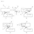
- FIG. 1 is a view sequentially showing a process of connecting an umbilical connection device for use, according to an exemplary embodiment of the present invention
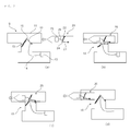
- FIG. 2 is a view sequentially showing a process of connecting an umbilical connection device for use, according to another exemplary embodiment of the present invention.
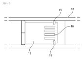
- FIG. 3 is a plan view showing a launch pad navel and a missile navel according to an exemplary embodiment of the present invention
- FIG. 4 is a perspective view showing a launch pad navel and a missile navel according to another exemplary embodiment of the present invention
- FIG. 5 is a plan view showing locking protrusions according to an exemplary embodiment of the present invention.
- An umbilical connection device that keeps or removes electric connection between a missile 20 mounted in a launch pipe 11 for launching and a launch pad 10, includes: a missile navel 21 that is hinged to a side of the missile 20 and pressed outside the missile 20 by a first pressing member 22; and a launch pad navel 12 that is hinged to a side of the launch pad 10, pressed against the missile navel 21 by a second pressing member 13, and electrically connected with the missile navel 21 that slides when the missile 20 is mounted and disconnected from the missile navel 21 that slides when the missile 20 is launched.
- the missile 20 is mounted in the launch pipe 11 of the launch pad 10 and the launch pipe 11 functions as a cylinder that protects the missile 20 from the outside before the missile 20 is launched and guides the motion of the missile 20 when the missile 20 is launched.
- the launch pad navel 12 has an end hinged to the launch pad 10, adjacent to the lower side of the launch pipe 11 in which the missile 20 is mounted, to rotate clockwise and counterclockwise about the hinge axis.
- the second pressing member 13 is disposed at one side of the launch pad navel 12 to press the launch pad navel 12 against the launch pipe 11.
- An electrode 16 is on the top of the launch pad navel 12 and electrically connected with a circuit board 15 of the launch pad 10 by a cable 14 such that power or signals are transmitted through the cable 14 therebetween.
- the circuit board 15 of the launch pad 10 may be equipped with a connector for fixing the cable 14.
- the missile navel 21 is hinged to the outer wall of a side of the missile 20 to rotate about the hinge axis.
- the first pressing member 22 is disposed at one side of the missile navel 21 to press the missile navel 21 to the outside of the missile 20.
- An electrode 24 is on the bottom of the missile navel 21 and electrically connected with a circuit board 23 of the missile 20 by a cable 26 such that power or signals are transmitted through the cable 26 therebetween. Further, the circuit board 23 of the missile 20 may be equipped with a connector for fixing the cable 26.
- the missile navel 21 slides to be electrically connected with the launch pad navel 12 of the launch pad 10 when the missile 20 is mounted in the launch pad 10. That is, the launch pad navel 12 pressed to the missile 20 and the missile navel 21 pressed to the launch pad navel 12 come in close contact with each other by means of the pressing force from the pressing members 13 and 22 when the missile 20 is mounted into the launch pipe 11, such that the electrodes 16 and 24 of the launch pad navel 12 and the missile navel 21 are electrically connected in contact with each other.
- the electrodes 16 and 24 of the launch pad navel 12 and the missile navel 21 may be formed in various shapes, and may be formed in a regular electrode array, as shown in FIG. 3 . That is, the launch pad navel 12 may be provided with the electrode 16 in various arrangements while the missile navel 21 is provided with the electrode 24 having a shape and a position corresponding to those of the electrode 16 of the launch pad navel 12. As described above, since the number of electrodes that are formed on the navels 12 and 21 increases, as compared with the related art, it is possible to transmit complicated and various signals through the navels 12 and 21.
- the launch pad navel 12 has guide protrusions 17 and the missile navel 21 may have guide grooves 25 shaped to correspond to the guide protrusions 17. Further, the ends of the guide protrusions 17 contacts with the bottoms of the guide grooves 25 and electrodes 16 and 24 are formed at the ends of the guide protrusions 17 and the bottoms of the guide grooves 25, such that they can be electrically connected with each other when the missile navel 21 slides in the launch pad navel 12.
- the launch pad navel 12 and the missile navel 21 may have any structures as long as they can contact with and separate from each other by sliding, when the guide protrusions 17 and the guide grooves 25 which guide the electrodes 16 and 26 to desired positions are formed, the electrodes 16 and 24 of the missile navel 21 and the launch pad navel 12 can be connected with each other at the accurate desired positions, when the missile 20 is mounted.
- the first pressing member 22 and the second pressing member 13, units for applying pressing force in predetermined directions to the missile navel 21 and the launch pad navel 12, may be coil springs in this embodiment.
- the first pressing member 22 and the second pressing member 13 may be implemented by other units that can press the missile navel 21 and the launch pad navel 12 in predetermined directions.
- the front end of the missile navel 21 may be hinged, as shown in FIG. 1 , or the rear end may be hinged, as shown in FIG. 2 , in the travel direction of the missile 20.
- the front end of the launch pad navel 12 may also be hinged, when the front end of the missile navel 21 is hinged.
- the pressing force from the first pressing member 22 may be larger than the pressing force from the second pressing member 13.
- the navels 12 and 21 are in contact toward the outside of the missile 20 by the pressing force from the first pressing member 22. That is, since the pressing force from the first pressing member 22 is larger than the pressing force from the second pressing member 13, the pressing force of the missile navel 21 is larger than the pressing force of the launch pad navel 12, such that the navels 12 and 21 rotate outside the missile 20 when contacting with each other.
- the launch pad 10 may have a retainer that prevents the launch pad navel 12 from rotating above a predetermined level, when the front end of the missile navel 21 is hinged.
- the retainer may be implemented by locking protrusions 19 that protrude in the rotational path of the launch pad navel 12, as shown in FIG. 5 .
- the launch pad navel 12 is rotated to the missile 20 by friction force, which may interfere with the travel of the missile 20. Therefore, it is possible to prevent the launch pad navel 12 from interfering with the travel of the missile 20, by preventing the launch pad navel 12 from rotating above a predetermined level, using the retainer, such as the locking protrusions 19.
- the rear end of the launch pad navel 12 may also be hinged, when the rear end of the missile navel 21 is hinged.
- the pressing force from the second pressing member 13 may be larger than the pressing force from the first pressing member 22.
- the navels 12 and 21 are in contact toward the inside of the missile 20, by means of the pressing force from the second pressing member 13. That is, since the pressing force from the second pressing member 13 is larger than the pressing force from the first pressing member 22, the pressing force of the launch pad navel 12 is larger than the pressing force of the missile navel 21, such that the navels 12 and 21 rotate inside the missile 20 when contacting with each other.
- the distances between the missile navel 21, the launch pad navel 12 and the pressing members 13 and 22 are at the maximum, as shown in (a) of FIG. 1 and (a) of FIG. 2 , before the missile 20 is mounted in the launch pad 10.
- the missile navel 21 first contacts with the launch pad navel 12, and then as the missile 20 continues moving forward, the missile navel 21 slides to be in close contact with the launch pad navel 12 by means of the pressing force from the pressing members 13 and 22.
- the electrodes 16 and 24 of the missile navel 21 and the launch pad navel 12 contact with each other to be electrically connected.
- the missile navel 21 and the launch pad navel 12 automatically contact with each other to be electrically connected, thereby easily mounting the missile 20.
- the missile 20 is launched and the missile navel 21 is slid by the propulsive force, such that the missile navel 21 and the launch pad navel 12 that has electrically connected with each other are separated.
- the navels 12 and 21 are separated without being damaged when the missile 20 launched, as described above, it is possible to semi-permanently use the umbilical connection device left on the launch pad 10 after the missile 20 has been launched.
Landscapes
- Engineering & Computer Science (AREA)
- General Engineering & Computer Science (AREA)
- Chemical & Material Sciences (AREA)
- Aviation & Aerospace Engineering (AREA)
- Combustion & Propulsion (AREA)
- Details Of Connecting Devices For Male And Female Coupling (AREA)
Applications Claiming Priority (1)
| Application Number | Priority Date | Filing Date | Title |
|---|---|---|---|
| KR1020100052431A KR101016686B1 (ko) | 2010-06-03 | 2010-06-03 | 배꼽 연결 장치 |
Publications (1)
| Publication Number | Publication Date |
|---|---|
| EP2392889A2 true EP2392889A2 (de) | 2011-12-07 |
Family
ID=43777778
Family Applications (1)
| Application Number | Title | Priority Date | Filing Date |
|---|---|---|---|
| EP11152199A Withdrawn EP2392889A2 (de) | 2010-06-03 | 2011-01-26 | Nabelschnurverbindungsvorrichtung |
Country Status (2)
| Country | Link |
|---|---|
| EP (1) | EP2392889A2 (de) |
| KR (1) | KR101016686B1 (de) |
Cited By (1)
| Publication number | Priority date | Publication date | Assignee | Title |
|---|---|---|---|---|
| US20230049500A1 (en) * | 2021-08-12 | 2023-02-16 | Raytheon Company | Translating harness with passive disconnect |
Families Citing this family (2)
| Publication number | Priority date | Publication date | Assignee | Title |
|---|---|---|---|---|
| KR101501498B1 (ko) * | 2013-10-21 | 2015-03-11 | 한국항공우주연구원 | 공압식 배꼽 커넥터 고정 장치 |
| KR102233743B1 (ko) * | 2020-07-23 | 2021-03-30 | 엘아이지넥스원 주식회사 | 유도발사 시스템 |
Family Cites Families (4)
| Publication number | Priority date | Publication date | Assignee | Title |
|---|---|---|---|---|
| KR100617367B1 (ko) * | 2001-12-31 | 2006-08-29 | 국방과학연구소 | 공압을 이용한 유도탄 자세유지장치 |
| KR100629930B1 (ko) * | 2004-07-30 | 2006-09-29 | 국방과학연구소 | 유도탄 사출 발사 장치 |
| JP4712511B2 (ja) * | 2005-10-13 | 2011-06-29 | ダイセル化学工業株式会社 | 接続及び分離装置 |
| KR100607107B1 (ko) * | 2006-06-09 | 2006-08-01 | 국방과학연구소 | 유도탄 발사 장치의 배꼽분리기구 |
-
2010
- 2010-06-03 KR KR1020100052431A patent/KR101016686B1/ko active Active
-
2011
- 2011-01-26 EP EP11152199A patent/EP2392889A2/de not_active Withdrawn
Non-Patent Citations (1)
| Title |
|---|
| None |
Cited By (2)
| Publication number | Priority date | Publication date | Assignee | Title |
|---|---|---|---|---|
| US20230049500A1 (en) * | 2021-08-12 | 2023-02-16 | Raytheon Company | Translating harness with passive disconnect |
| US11709035B2 (en) * | 2021-08-12 | 2023-07-25 | Raytheon Company | Translating harness with passive disconnect |
Also Published As
| Publication number | Publication date |
|---|---|
| KR101016686B1 (ko) | 2011-02-25 |
Similar Documents
| Publication | Publication Date | Title |
|---|---|---|
| US9419367B2 (en) | Pluggable connector having multiple housing shells | |
| US9385466B2 (en) | Retention features for cable assembly of a pluggable connector | |
| US8794991B2 (en) | Electrical connector including guidance and latch assembly | |
| US9705229B2 (en) | Connector assembly | |
| CN102570216B (zh) | 射频模块 | |
| US8672696B2 (en) | Hybrid connector and cable with said connector | |
| US9287660B2 (en) | Pluggable connector having a coupling mechanism | |
| US9484657B2 (en) | Harness connector having a power and signal cartridges | |
| US11465517B2 (en) | Electric charging connection for heavy vehicles | |
| EP2737578A1 (de) | Elektrischer verbinder mit einem steckdrahtkontakt | |
| US9543722B2 (en) | Connector for supporting electronic device | |
| US10014619B2 (en) | Angle connector | |
| EP3066726B1 (de) | Schwimmerplatte für stromkabel-blindstecker | |
| US20120231673A1 (en) | Receptacle connector and plug connector to be fitted to the receptacle connector | |
| EP3381094B1 (de) | Elektrischer steckverbinder | |
| US20150318633A1 (en) | Pluggable connector having a protective front wall | |
| US9209572B1 (en) | Pluggable connector configured to reduce electromagnetic interference leakage | |
| US10971851B2 (en) | Miniaturized connector with a terminal holding member | |
| EP2392889A2 (de) | Nabelschnurverbindungsvorrichtung | |
| EP3195413A1 (de) | Elektrische steckverbinder | |
| KR20160057150A (ko) | 탈부착이 가능한 셀탭 커넥터 | |
| EP2920541B1 (de) | Versorgungskabeltrennung | |
| CN111834770B (zh) | 连结器 | |
| US10768375B2 (en) | Electro-optical connectors | |
| EP2515389B1 (de) | Elektrischer steckerartiger Verbinder |
Legal Events
| Date | Code | Title | Description |
|---|---|---|---|
| 17P | Request for examination filed |
Effective date: 20110126 |
|
| AK | Designated contracting states |
Kind code of ref document: A2 Designated state(s): AL AT BE BG CH CY CZ DE DK EE ES FI FR GB GR HR HU IE IS IT LI LT LU LV MC MK MT NL NO PL PT RO RS SE SI SK SM TR |
|
| AX | Request for extension of the european patent |
Extension state: BA ME |
|
| PUAI | Public reference made under article 153(3) epc to a published international application that has entered the european phase |
Free format text: ORIGINAL CODE: 0009012 |
|
| STAA | Information on the status of an ep patent application or granted ep patent |
Free format text: STATUS: THE APPLICATION IS DEEMED TO BE WITHDRAWN |
|
| 18D | Application deemed to be withdrawn |
Effective date: 20130801 |