EP2392794B1 - Separately cooled turbo charger for maintaining a no-flow strategy of a cylinder block coolant lining - Google Patents
Separately cooled turbo charger for maintaining a no-flow strategy of a cylinder block coolant lining Download PDFInfo
- Publication number
- EP2392794B1 EP2392794B1 EP10165035.6A EP10165035A EP2392794B1 EP 2392794 B1 EP2392794 B1 EP 2392794B1 EP 10165035 A EP10165035 A EP 10165035A EP 2392794 B1 EP2392794 B1 EP 2392794B1
- Authority
- EP
- European Patent Office
- Prior art keywords
- coolant
- coolant jacket
- cylinder block
- exhaust
- turbine housing
- Prior art date
- Legal status (The legal status is an assumption and is not a legal conclusion. Google has not performed a legal analysis and makes no representation as to the accuracy of the status listed.)
- Active
Links
- 239000002826 coolant Substances 0.000 title claims description 224
- 238000001816 cooling Methods 0.000 claims description 50
- 238000002485 combustion reaction Methods 0.000 claims description 35
- 238000011144 upstream manufacturing Methods 0.000 claims description 8
- XAGFODPZIPBFFR-UHFFFAOYSA-N aluminium Chemical compound [Al] XAGFODPZIPBFFR-UHFFFAOYSA-N 0.000 claims description 4
- 229910052782 aluminium Inorganic materials 0.000 claims description 4
- 238000000034 method Methods 0.000 claims description 4
- 239000003562 lightweight material Substances 0.000 claims description 2
- 239000007789 gas Substances 0.000 description 21
- 229910001208 Crucible steel Inorganic materials 0.000 description 7
- 238000010438 heat treatment Methods 0.000 description 5
- 238000004891 communication Methods 0.000 description 4
- 239000000446 fuel Substances 0.000 description 4
- 239000000463 material Substances 0.000 description 4
- PXHVJJICTQNCMI-UHFFFAOYSA-N Nickel Chemical compound [Ni] PXHVJJICTQNCMI-UHFFFAOYSA-N 0.000 description 2
- 229910045601 alloy Inorganic materials 0.000 description 2
- 239000000956 alloy Substances 0.000 description 2
- 238000005275 alloying Methods 0.000 description 2
- 239000003054 catalyst Substances 0.000 description 2
- 238000010586 diagram Methods 0.000 description 2
- 230000000694 effects Effects 0.000 description 2
- 239000003507 refrigerant Substances 0.000 description 2
- 230000003685 thermal hair damage Effects 0.000 description 2
- 238000007872 degassing Methods 0.000 description 1
- 238000013461 design Methods 0.000 description 1
- 230000002349 favourable effect Effects 0.000 description 1
- 230000005764 inhibitory process Effects 0.000 description 1
- 239000010687 lubricating oil Substances 0.000 description 1
- 239000010705 motor oil Substances 0.000 description 1
- 229910052759 nickel Inorganic materials 0.000 description 1
- 239000003921 oil Substances 0.000 description 1
- 238000005192 partition Methods 0.000 description 1
- 238000011084 recovery Methods 0.000 description 1
- 238000005057 refrigeration Methods 0.000 description 1
- 238000012546 transfer Methods 0.000 description 1
- 238000013022 venting Methods 0.000 description 1
- XLYOFNOQVPJJNP-UHFFFAOYSA-N water Substances O XLYOFNOQVPJJNP-UHFFFAOYSA-N 0.000 description 1
Images


Classifications
-
- F—MECHANICAL ENGINEERING; LIGHTING; HEATING; WEAPONS; BLASTING
- F01—MACHINES OR ENGINES IN GENERAL; ENGINE PLANTS IN GENERAL; STEAM ENGINES
- F01P—COOLING OF MACHINES OR ENGINES IN GENERAL; COOLING OF INTERNAL-COMBUSTION ENGINES
- F01P7/00—Controlling of coolant flow
- F01P7/14—Controlling of coolant flow the coolant being liquid
- F01P7/16—Controlling of coolant flow the coolant being liquid by thermostatic control
- F01P7/165—Controlling of coolant flow the coolant being liquid by thermostatic control characterised by systems with two or more loops
-
- F—MECHANICAL ENGINEERING; LIGHTING; HEATING; WEAPONS; BLASTING
- F02—COMBUSTION ENGINES; HOT-GAS OR COMBUSTION-PRODUCT ENGINE PLANTS
- F02B—INTERNAL-COMBUSTION PISTON ENGINES; COMBUSTION ENGINES IN GENERAL
- F02B39/00—Component parts, details, or accessories relating to, driven charging or scavenging pumps, not provided for in groups F02B33/00 - F02B37/00
- F02B39/005—Cooling of pump drives
-
- F—MECHANICAL ENGINEERING; LIGHTING; HEATING; WEAPONS; BLASTING
- F01—MACHINES OR ENGINES IN GENERAL; ENGINE PLANTS IN GENERAL; STEAM ENGINES
- F01P—COOLING OF MACHINES OR ENGINES IN GENERAL; COOLING OF INTERNAL-COMBUSTION ENGINES
- F01P3/00—Liquid cooling
- F01P3/02—Arrangements for cooling cylinders or cylinder heads
- F01P2003/027—Cooling cylinders and cylinder heads in parallel
-
- F—MECHANICAL ENGINEERING; LIGHTING; HEATING; WEAPONS; BLASTING
- F01—MACHINES OR ENGINES IN GENERAL; ENGINE PLANTS IN GENERAL; STEAM ENGINES
- F01P—COOLING OF MACHINES OR ENGINES IN GENERAL; COOLING OF INTERNAL-COMBUSTION ENGINES
- F01P2060/00—Cooling circuits using auxiliaries
- F01P2060/12—Turbo charger
-
- F—MECHANICAL ENGINEERING; LIGHTING; HEATING; WEAPONS; BLASTING
- F01—MACHINES OR ENGINES IN GENERAL; ENGINE PLANTS IN GENERAL; STEAM ENGINES
- F01P—COOLING OF MACHINES OR ENGINES IN GENERAL; COOLING OF INTERNAL-COMBUSTION ENGINES
- F01P2060/00—Cooling circuits using auxiliaries
- F01P2060/16—Outlet manifold
Definitions
- the invention relates to an internal combustion engine having a cylinder block coolant jacket and a cylinder head coolant jacket, wherein a turbocharger is arranged with its turbine in an exhaust line.
- the EP 0 038 556 B1 describes a cooling system for an internal combustion engine.
- a first pump coolant is conveyed through a cylinder head cooling jacket.
- a second pump delivers coolant through the cylinder block coolant jacket.
- Both cooling jackets have no connection within the internal combustion engine, but discharge on the output side in a main circulation line system.
- a radiator bypass line system which leads to the cylinder head inlet of the head cooling jacket and to the cylinder block inlet of the cylinder block coolant jacket.
- a control valve By means of a control valve, a flow of coolant to the radiator is prevented and a flow of coolant through the radiator bypass system is allowed.
- a coolant flow through the cylinder block coolant jacket is interrupted by means of a second control valve.
- z. B. attributed to the applicant EP 1 900 919 A1 a separate coolant circuit of an internal combustion engine, wherein a cylinder head coolant jacket and an engine block coolant jacket is provided, wherein the separate coolant circuit comprises a pump, a radiator, a thermostat and a heater, and wherein a coolant circulates in the separate coolant circuit.
- the thermostat is arranged to control the flow of the coolant through both the engine block coolant jacket and the radiator when the coolant exceeds a predetermined temperature.
- Similar internal combustion engines are off FR2936566 and WO2007 / 058225 known.
- the no-flow strategy for the cylinder block coolant jacket can be maintained longer, as these areas, in which otherwise accumulate hot vapors, flowed through by coolant can, so that thermal damage in these areas are advantageously avoided.
- Turbochargers comprise a turbine and a compressor, wherein the turbine is driven by means of the exhaust gas streams, so that the compressor side compressed air can generate, which is supplied to the internal combustion engine.
- the turbine housing is made of a high-alloy cast steel, to withstand the high temperature loads of the exhaust gases.
- the cast steel is very expensive to produce, in particular due to its alloying elements, for example nickel with about 37 wt .-%.
- cast steel is not only expensive but also has a relatively high weight, with any additional weight having a negative effect on the fuel consumption of the entire motor vehicle.
- the invention has the object to improve an internal combustion engine of the type mentioned with simple means so that in spite of the NO-flow strategy for the cylinder block coolant jacket sufficient heat flow z. B. is achievable for a cabin heater, which also benefits in terms of reduced weight, in particular the turbocharger to be achieved in order to reduce fuel consumption.
- the object is achieved by an internal combustion engine with the features of claim 1, wherein the turbocharger, preferably its turbine housing, a separate from the cylinder block coolant jacket cooling circuit, which is connected to a common pump, with a bypass leading at least to the turbocharger downstream of the pump and is provided upstream of a block water inlet.
- the turbocharger preferably its turbine housing, a separate from the cylinder block coolant jacket cooling circuit, which is connected to a common pump, with a bypass leading at least to the turbocharger downstream of the pump and is provided upstream of a block water inlet.
- the no-flow strategy of the cylinder block coolant jacket in particular after a cold start of the internal combustion engine, can be maintained as long as possible, since the turbocharger or its turbine housing is quasi provided with an external, separate from the actual engine cooling circuit, coolant circuit.
- Conceivable is a heat recovery from the exhaust gases
- the recovered heat can also be used to heat the structure of the engine
- the recovered heat can also be used to heat operating media and / or a cabin heating can be supplied.
- the cabin heating can be provided in spite of the no-flow concept of the cylinder block coolant jacket as a sufficient heat flow available.
- a further advantage is that it is possible with the solution according to the invention to produce the turbine housing from a material which has to withstand a reduced thermal load due to the cooling.
- a cost-intensive cast steel with its very expensive alloying elements can be virtually dispensed with.
- the invention it is also possible with the invention to dispense with a manufactured from heavy cast steel turbine housing and to use other, lighter materials, which are also cheaper to produce.
- the turbine housing could be made of aluminum. This leads to the further apparent advantage of being able to use a very lightweight turbine housing, based on cast steel, as a result of which fuel consumption can be further reduced.
- the advantageous choice of the material aluminum is possible in particular because of the inventively provided cooling.
- bypass leads directly to the turbocharger or its turbine housing to provide them with the necessary coolant. Downstream (based on the coolant flow) of the turbine housing opens a coolant line in the coolant circuit.
- the exhaust gas collector into the cylinder head, that is to say in one piece, preferably monolithically, with it (Integrated Exhaust Manifold; IEM).
- IEM Integrated Exhaust Manifold
- the exhaust pipes of each cylinder a four-cylinder engine usually has an exhaust pipe for each cylinder
- the exhaust manifold and open in a common exhaust pipe, which leads to the exhaust system, in which exhaust aftertreatment devices such.
- B. a catalyst is arranged. This reduces the effective surface area, making it possible to bring the exemplary catalyst to its operating temperature faster.
- the integrated exhaust collector can also have a separate coolant circuit in order to be able to use exhaust heat as before.
- the two components turbine housing and exhaust manifold or integrated exhaust manifold relative to the coolant flow may be quasi-parallel connected.
- exhaust manifold / turbine In a further advantageous embodiment can be provided to switch the two components (exhaust manifold / turbine) based on the flow of coolant in series.
- it may be provided to initially lead the bypass into the input side of the integrated exhaust manifold, wherein the output connection line opens into the turbine housing. From the turbine housing can then lead a connecting line to the coolant circuit in this opening.
- the exhaust manifold would be arranged upstream of the turbine housing relative to the coolant flow.
- the bypass may be incorporated in the engine and extend from the pump through both the engine block and the cylinder head toward the coolant jacket of the exhaust manifold.
- the bypass can advantageously be designed as a channel molded into the components or as a drilled channel, ie as a coolant channel.
- the bypass is thus integrated as a coolant channel between the coolant pump and the cylinder head in the cylinder block.
- bypass outside the engine is designed as an external line, which may be in communication with the coolant jacket of the turbocharger or its turbine housing and / or the exhaust manifold.
- the invention thus provides a turbocharger or its turbine housing which has a separate coolant jacket which, at least in the warm-up phase of the internal combustion engine or in a partial phase thereof, is separated from the cylinder block coolant jacket.
- the "no-flow strategy" of the cylinder block coolant jacket can be maintained for a particularly long time, even when vehicle occupants request, for example, the cabin heater. Because by the (additional) heat input via the exhaust gases into the coolant, so the cabin heater can take over their function without burdening the actual cooling circuit of the cylinder block coolant jacket.
- the cylinder head may have at its inlet side to its outlet side (here, the integrated exhaust manifold may be arranged) separate coolant circuit (split-cooling).
- this inlet side coolant jacket of the cylinder head is not in contact with the coolant jacket of the turbine housing or the exhaust manifold.
- the cylinder block coolant jacket communicates with the inlet-side cylinder head coolant jacket via corresponding devices, so that the hot coolant vapors forming during the zero flow of the coolant in the cylinder block coolant jacket (no-flow strategy) are produced through bores or degassing bores in the cylinder head gasket can be discharged into the intake-side cylinder head coolant jacket.
- the no-flow strategy is limited within the meaning of the invention only to the cylinder block coolant jacket. This means that a coolant flow in the cylinder block coolant jacket is prevented almost completely (ie, except for small amounts of leakage), wherein in the turbine housing and / or in the Cylinder head, but especially in its outlet side coolant jacket in the warm-up phase, especially in a first warm-up phase (partial phase) permanently flows coolant.
- the separate cooling circuit of the turbocharger so the turbine housing and / or the exhaust manifold with the cooling circuit of the internal combustion engine, ie with the inlet side Cylinder Head coolant jacket and the cylinder block coolant jacket can be interconnected.
- the invention thus also provides a cooling strategy for an internal combustion engine, or a method for coolant control during the warm-up phase or during a first partial phase of the warm-up phase of the internal combustion engine, in which a coolant flow, starting from a pump common to the cylinder block coolant jacket, bypasses the cylinder block coolant jacket and in the warm-up phase is guided without contact to this by a separate bypass to the turbocharger or to its turbine housing, with a permanent flow of coolant can be reached.
- the thermostat is arranged between a coolant pump outlet and the cylinder block coolant jacket inlet.
- the thermostat is integrated in the cylinder block, wherein the bypass branches off from the thermostat.
- the thermostat is arranged so that it is controlled by the temperature of the coolant in the cylinder block coolant jacket, ie is advantageously not controlled by the temperature of the coolant, which is not in the cylinder block.
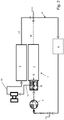
- FIG. 1 shows an internal combustion engine 1 with an engine block 2 and a cylinder head, wherein in the figures, only the outlet side 3 of the cylinder head is shown.
- the outlet 3 is designed with an integrated exhaust manifold.
- the cylinder head includes a cylinder head coolant jacket and a cylinder block coolant jacket, the integrated exhaust manifold having a separate coolant jacket.
- the internal combustion engine 1 has a coolant circuit 4, which has a cabin heater 6.
- a pump 7 is arranged, which promotes coolant to a split-cooling thermostat 8.
- the split cooling thermostat 8 is disposed on an input side 9 of the cylinder block coolant jacket.
- Other components of the cooling circuit such as a venting device, a main cooler, other thermostats, lines or connecting lines, other bypass, oil cooler and main thermostat are not shown in the figures.
- a bypass 11 branches off from the split cooling thermostat 8 (cylinder block thermostat 8).
- the bypass 11 leads to a turbocharger 12, or to its turbine housing 13, which is arranged in an exhaust line of the internal combustion engine 1. From the turbine housing 13, a return line 14 leads to the coolant circuit 4 in this opening.
- the internal combustion engine 1 or the cylinder block coolant jacket and the cylinder head coolant jacket is operated with the so-called split cooling strategy, which means that the split cooling thermostat 8 prevents coolant flow in the cylinder block coolant jacket in at least one partial phase of the warm-up phase of the internal combustion engine 1.
- Flow strategy can be called.
- the no-flow strategy can be maintained, even if e.g. the cabin heater 6 is requested.
- the bypass 11 is advantageously provided, which allows a flow of coolant to the turbocharger 12 and the turbine housing 13, even if a coolant flow in the cylinder block coolant jacket has an amount of zero, or is continuously increased during further phases of the warm-up phase.
- the exhaust heat of the exhaust gases flowing through the turbine can be recovered, and z. B. the cabin heater 6 are supplied.
- a further advantage of the invention with regard to a possible choice of material is at least the turbine housing 13. Due to the cooling of the turbine housing 13, or due to the possible permanent coolant flow For this, can be dispensed with a costly cast steel alloy, with advantageous lightweight materials such. B. aluminum can be used.
- an input connection line 16 branches off from the bypass 11 and leads to the coolant jacket of the integrated exhaust gas collector.
- an output connection line 17 leads to the coolant circuit 4 in this opening.
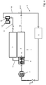
- FIG. 2 a series circuit of the coolant jacket of the turbine housing 13 and the coolant jacket of the exhaust manifold and the integrated exhaust manifold shown.
- the bypass 11 initially leads coolant to the turbine housing 13 and from here with its return line 14 exiting to the coolant jacket of the exhaust manifold.
- the return line 14 may also be referred to as the input connection line 16.
- the output connection line 17 leads to the coolant circuit 4 in this opening.
- the turbocharger 12 or its turbine housing 13 is arranged upstream of the exhaust gas collector or the integrated exhaust gas collector with respect to the coolant flow. Dashed lines the output line 18 of the cylinder block coolant jacket is shown, which opens into the cooling circuit 4.
- the output line 18 can optionally also open downstream of the turbine housing 13 and upstream of the exhaust manifold in the return line 14.
- the output line 18 as well FIG. 2 be described in opening into the cooling circuit 4, so that the output line 18 is divided into two sub-branches quasi.
- the branching into the return line 14 would then flow depending on the pressure drop in the turbine housing 13 (based on the coolant flow in this), wherein the other coolant flow flows into the cooling circuit 4.
- a control for controlling an adjustable amount of the refrigerant flow in the respective branch may also be provided.
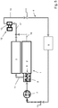
- FIG. 4 based on the coolant flow is also shown a series connection of the two components turbine housing 13 and exhaust manifold.
- the turbine housing 13 is arranged downstream of the exhaust gas collector with respect to the coolant flow.
- the bypass 11 leads directly into the input side of the coolant jacket of the exhaust manifold, from the output side, the output connection line 17 leads to the coolant jacket of the turbine housing 13.
- Downstream of the turbine housing 13 opens its coolant jacket via the return line 14 in the cooling circuit 4.
- Dashed lines again the output line 18 of the cylinder block coolant jacket is shown, which as in the embodiment to FIG. 2 downstream of the turbine housing 13 in the cooling circuit 4 opens.
- FIG. 5 is the series connection according to FIG. 4 illustrated, wherein the output line 18, however, opens upstream of the turbine housing in the output connection line 17.
- a branching out into two sub-branches output line 18 may be provided so that the opening into the output connection line 17 branch would then flow depending on the pressure drop (based on the coolant flow), the other coolant flow flows into the cooling circuit 4.
- a control element for controlling an adjustable amount of the coolant flow in the respective branch can also be provided here.
- the internal combustion engine is shown only in principle.
- the cylinder block coolant jacket may communicate with an intake side cylinder head coolant jacket (bores or vent holes in the cylinder head gasket).
- the split cooling thermostat 8 In a warm-up phase of the internal combustion engine 1, that is, for example, after its cold start, the split cooling thermostat 8 is closed, so that in the engine block or in the cylinder block coolant jacket a coolant zero flow (except for small leakage quantities) is applied.
- the hot refrigerant vapors thereby formed can be discharged to the intake side cylinder head coolant jacket via the connection of the cylinder block coolant jacket.
- the no-flow strategy of the cylinder block coolant jacket can be maintained for a particularly long time without fear of thermal damage.
- exhaust heat can be absorbed by the flowing in the turbine housing 13 and / or in the integrated exhaust manifold or in the outlet side cylinder head coolant jacket coolant and transported to the cabin heater 6 (additional heat input via exhaust gases), without that the no-flow strategy of Cylinder block coolant jacket would have to be abandoned, so that the negative effect of the split-cooling concept with respect to the reduced heat output in the passenger compartment with the invention, if not completely, at least partially compensated. From the cabin heater 6, the coolant flows back to the pump. 7
- the coolant pump can be received in a cover (front cover), or covered by this.
- the coolant pump 7 delivers a coolant flow to the split cooling thermostat 8, which z. B. is accommodated in a thermostat housing, and a coolant branch to the cylinder block coolant jacket and controlled to the bypass 11, wherein the bypass 11 is always open, so that at least the coolant jacket of the turbine housing 13 is continuously flowed through by coolant.
- the split cooling thermostat 8 is arranged between a pump outlet and a cylinder block coolant jacket inlet and preferably integrated with its housing in the cylinder block.
- the split cooling thermostat 8 is favorably arranged so that it is controlled by the temperature of the coolant in the cylinder block coolant jacket, that allows coolant flow into or in the cylinder block coolant jacket when the coolant temperature in the cylinder block coolant jacket has the required amount.
- the split cooling thermostat 8 blocks the cylinder block coolant jacket, so that the no-flow strategy is carried out, which means in the meaning of the invention but a zero coolant flow (except for small leakage quantities) only for the cylinder block coolant jacket.
- bypass 11 and the coolant channels 11, which are exemplified by the cylinder block, the cylinder head gasket and the cylinder head in the outlet side cylinder head coolant jacket are always open, so are not controlled by the split cooling thermostat 8.
- a separate bypass 11 which exemplifies as in FIG. 1 shown leads to the turbine housing 13.
- the coolant flow through the integrated in the cylinder head exhaust manifold (upper shell / lower shell) or through the outlet side of the cylinder head reaches such. B. in an outlet housing, which may be in communication with the cabin heater 6, wherein the coolant flowing through the turbine housing 13 is also in communication with the cabin heater 6.
- the cabin heater 6 can be operated by supplying heat from the exhaust gases (additional Heat input from the exhaust gases into the coolant for cabin heating 6), without interrupting the no-flow strategy of the cylinder block coolant jacket.
- the cylinder head still has the inlet side coolant jacket in addition to the cooled exhaust manifold.
- the inlet-side coolant jacket is separated from the coolant jacket of the exhaust gas collector or the outlet side by means of a partition wall.
- coolant flows in addition through the split cooling thermostat. 8 into the cylinder block coolant jacket and through corresponding bores in the inlet-side coolant jacket of the cylinder head, from where the coolant passes by way of example into the outlet housing and mixes with the outlet-side coolant stream.
- coolant can also be dispensed with an outlet housing, with a mixing can then be done in the cabin heater 6 and / or in the supply line.
- such a cooling strategy or a method for the separate passage of certain cooling areas can be provided, in which the engine block (no-flow strategy) is not flowed through in the warm-up phase, wherein the turbine housing 13, and / or the outlet side of Cylinder head, in particular the integrated exhaust collector, is continuously flowed through, so that the flowing coolant can absorb exhaust heat and transport to the cabin heater 6.
Landscapes
- Engineering & Computer Science (AREA)
- Chemical & Material Sciences (AREA)
- Combustion & Propulsion (AREA)
- Mechanical Engineering (AREA)
- General Engineering & Computer Science (AREA)
- Supercharger (AREA)
- Cylinder Crankcases Of Internal Combustion Engines (AREA)
Description
Die Erfindung betrifft einen Verbrennungsmotor, der einen Zylinderblockkühlmittelmantel und einen Zylinderkopfkühlmittelmantel aufweist, wobei ein Turbolader mit seiner Turbine in einem Abgasstrang angeordnet ist.The invention relates to an internal combustion engine having a cylinder block coolant jacket and a cylinder head coolant jacket, wherein a turbocharger is arranged with its turbine in an exhaust line.
Die
Bekannter Weise ist es zweckmäßig, den Motorblock und den Zylinderkopf des Verbrennungsmotors jeweils getrennt voneinander mit einem Kühlmittel eines Kühlmittelkreislaufs durchströmen zu lassen. Auf diese Weise können der Zylinderkopf, der thermisch vor allem mit der Brennraumwand und der Abgasführung gekoppelt ist und der Motorblock, der thermisch vor allem mit den Reibstellen gekoppelt ist, unterschiedlich gekühlt werden. Durch dieses so genannte "Split-Cooling-System" (getrennter Kühlmittelkreislauf) soll erreicht werden, dass in der Warmlaufphase des Verbrennungsmotors der Zylinderkopf gekühlt wird, wobei der Motorblock zunächst noch nicht gekühlt werden soll (no-flow-Strategie), so dass der Motorblock schneller auf die erforderliche Betriebstemperatur geführt werden kann.Known manner, it is expedient to let flow through the engine block and the cylinder head of the engine separately from each other with a coolant of a coolant circuit. In this way, the cylinder head, which is thermally coupled above all with the combustion chamber wall and the exhaust system and the engine block, which is thermally coupled above all with the friction points, can be cooled differently. By this so-called "split-cooling system" (separate coolant circuit) is to be achieved that in the warm-up phase of the engine, the cylinder head is cooled, the engine block is not yet to be cooled (no-flow strategy), so that the Engine block faster to the required operating temperature can be performed.
So offenbart z. B. die auf die Anmelderin zurückgehende
Mit diesen Maßnahmen (Split cooling) können in der Warmlaufphase ReibungsVerluste reduziert werden. Es ist aber auch bekannt, das Motoröl aufzuwärmen, das Kühlmittel aufzuwärmen, oder die Oberflächen der Kolbenhemden schneller aufzuwärmen.With these measures (split cooling), friction losses can be reduced during the warm-up phase. However, it is also known to warm up the engine oil, to heat the coolant, or to warm up the surfaces of the piston shirts faster.
Es wird angestrebt, die Unterbindung der Kühlmittelströmung durch den Zylinderblockkühlmittelmantel (die so genannte "No-Flow Strategie" für den Zylinderblockkühlmittelmantel") so lange wie möglich aufrecht zu erhalten, um Reibungsverluste während der Warmlaufphase, insbesondere nach einem Kaltstart des Verbrennungsmotors, zu reduzieren. Bekannt ist zum Beispiel, eine interne Verbindung zwischen dem Zylinderblockkühlmittelmantel und dem Zylinderkopfkühlmittelmantel herzustellen, so dass während der NULL-Strömung im Zylinderblockkühlmittelmantel entstehender Kühlmitteldampf in den Kopfkühlmittelmantel, vorzugsweise in den einlaßseitigen Kopfkühlmittelmantel, geleitet werden kann. Durch die Ableitung der heißen Gase (diese sammeln sich naturgemäß an einem oberen Bereich) kann die No-Flow Strategie für den Zylinderblockkühlmittelmantel länger aufrechterhalten werden, da diese Bereiche, in denen sich ansonsten heiße Dämpfe ansammeln, von Kühlmittel durchflossen werden können, so dass thermische Schäden in diesen Bereichen vorteilhaft vermieden sind.It is desirable to maintain the inhibition of coolant flow through the cylinder block coolant jacket (the so-called "no-flow strategy" for the cylinder block coolant jacket) as long as possible to reduce friction losses during the warm-up phase, particularly after a cold start of the internal combustion engine. For example, it is known to make an internal connection between the cylinder block coolant jacket and the cylinder head coolant jacket so that coolant vapor arising during ZERO flow in the cylinder block coolant jacket can be directed into the head coolant jacket, preferably into the inlet side head coolant jacket Naturally, at an upper portion), the no-flow strategy for the cylinder block coolant jacket can be maintained longer, as these areas, in which otherwise accumulate hot vapors, flowed through by coolant can, so that thermal damage in these areas are advantageously avoided.
Bei der No-Flow-Strategie für den Zylinderblockkühlmittelmantel bzw. bei dem Split-Cooling Konzept kann es passieren, dass zu wenig Wärme z. B. zu einer Kabinenheizung gelangt, um die Kabine aufzuwärmen oder um z. B. Scheiben zu entfrosten.In the no-flow strategy for the cylinder block coolant jacket or in the split-cooling concept, it may happen that too little heat z. B. gets to a cabin heater to warm the cabin or z. As to defrost discs.
Turbolader weisen eine Turbine und einen Kompressor auf, wobei die Turbine mittels der Abgasströme angetrieben wird, so dass die Kompressorseite verdichtete Luft erzeugen kann, welche dem Verbrennungsmotor zugeführt wird. Beispielsweise das Turbinengehäuse ist aus einem hochlegierten Stahlguß hergestellt, um den hohen Temperaturbelastungen der Abgase standzuhalten. Der Stahlguß ist insbesondere aufgrund seiner Legierungselemente, beispielsweise Nickel mit ca. 37 Gew.-%, sehr kostenintensiv herzustellen. Stahlguß ist jedoch nicht nur kostenintensiv sondern weist auch ein relativ hohes Gewicht auf, wobei sich jedes zusätzliche Gewicht negativ auf den Kraftstoffverbrauch des Gesamtkraftfahrzeuges auswirkt.Turbochargers comprise a turbine and a compressor, wherein the turbine is driven by means of the exhaust gas streams, so that the compressor side compressed air can generate, which is supplied to the internal combustion engine. For example, the turbine housing is made of a high-alloy cast steel, to withstand the high temperature loads of the exhaust gases. The cast steel is very expensive to produce, in particular due to its alloying elements, for example nickel with about 37 wt .-%. However, cast steel is not only expensive but also has a relatively high weight, with any additional weight having a negative effect on the fuel consumption of the entire motor vehicle.
Von daher liegt der Erfindung die Aufgabe zugrunde, einen Verbrennungsmotor der eingangs genannten Art mit einfachen Mitteln so zu verbessern, bei welchem trotz der NO-Flow Strategie für den Zylinderblockkühlmittelmantel ein ausreichender Wärmestrom z. B. für eine Kabinenheizung erreichbar ist, wobei zudem Vorteile hinsichtlich verringerten Gewichts insbesondere des Turboladers erzielt werden sollen, um den Kraftstoffverbrauch zu reduzieren.Therefore, the invention has the object to improve an internal combustion engine of the type mentioned with simple means so that in spite of the NO-flow strategy for the cylinder block coolant jacket sufficient heat flow z. B. is achievable for a cabin heater, which also benefits in terms of reduced weight, in particular the turbocharger to be achieved in order to reduce fuel consumption.
Erfindungsgemäß wird die Aufgabe durch einen Verbrennungsmotor mit den Merkmalen des Anspruchs 1 gelöst, wobei der Turbolader, bevorzugt sein Turbinengehäuse, einen von dem Zylinderblockkühlmittelmantel getrennten Kühlkreislauf aufweist, welcher mit einer gemeinsamen Pumpe verbunden ist, wobei ein Bypaß zumindest zum Turbolader führend stromab der Pumpe und stromauf eines Blockwassereingangs vorgesehen ist.According to the invention the object is achieved by an internal combustion engine with the features of
Es ist darauf hinzuweisen, dass die nicht nur in den Patentansprüchen einzeln aufgeführten Merkmale in beliebiger, technisch sinnvoller Weise miteinander kombiniert werden können und weitere Ausgestaltungen der Erfindung aufzeigen. Die Beschreibung charakterisiert und spezifiziert die Erfindung insbesondere im Zusammenhang mit den Figuren zusätzlich.It should be noted that the features listed individually not only in the patent claims can be combined with one another in any technically meaningful manner and show further embodiments of the invention. The description additionally characterizes and specifies the invention, in particular in connection with the figures.
Mit der Erfindung kann so die No-Flow Strategie des Zylinderblockkühlmittelmantels, insbesondere nach einem Kaltstart des Verbrennungsmotors, so lange wie möglich aufrechterhalten werden, da der Turbolader bzw. sein Turbinengehäuse quasi mit einem externen, von dem eigentlichen Motorkühlkreislauf getrennten, Kühlmittelkreislauf versehen ist. So kann die Wärme der durch die Turbine strömenden Abgase in dem Turbinengehäuse von dem in dem Kühlmittelkreislauf zirkulierenden Kühlmittel aufgenommen, sozusagen rück gewonnen werden, und beispielsweise einer Kabinenheizung zugeführt werden, ohne dass die No-Flow Strategie des Zylinderblockkühlmittelmantels aufgegeben werden muß, wobei vorteilhaft eine schnellere Aufwärmung von Reibflächen und von Betriebsmedien, wie z. B. von Schmieröl erreicht wird. Dies reduziert z. B. den Kraftstoffverbrauch des Verbrennungsmotors. Denkbar ist also eine Wärmerückgewinnung aus den Abgasen, wobei die rückgewonnene Wärme auch zur Aufwärmung der Struktur des Verbrennungsmotors genutzt werden kann, wobei die rückgewonnene Wärme ebenfalls zur Erwärmung von Betriebsmedien genutzt und/oder einer Kabinenheizung zugeführt werden kann. Insbesondere der Kabinenheizung kann trotz des No-Flow Konzeptes des Zylinderblockkühlmittelmantels so ein ausreichender Wärmestrom zur Verfügung gestellt werden.With the invention, the no-flow strategy of the cylinder block coolant jacket, in particular after a cold start of the internal combustion engine, can be maintained as long as possible, since the turbocharger or its turbine housing is quasi provided with an external, separate from the actual engine cooling circuit, coolant circuit. Thus, the heat of the exhaust gases flowing through the turbine in the turbine housing from that in the coolant circuit taken, so to speak reclaimed, and be supplied, for example, a cabin heater, without the no-flow strategy of the cylinder block coolant jacket must be abandoned, advantageously a faster heating of friction surfaces and operating media, such as. B. is achieved by lubricating oil. This reduces z. B. the fuel consumption of the engine. Conceivable, therefore, is a heat recovery from the exhaust gases, the recovered heat can also be used to heat the structure of the engine, the recovered heat can also be used to heat operating media and / or a cabin heating can be supplied. In particular, the cabin heating can be provided in spite of the no-flow concept of the cylinder block coolant jacket as a sufficient heat flow available.
Vorteilhaft ist weiter, dass mit der erfindungsgemäßen Lösung möglich ist, das Turbinengehäuse aus einem Material herzustellen, welches aufgrund der Kühlung einer verringerten thermischen Belastung standhalten muß. Insofern kann auf einen kostenintensiven Stahlguß mit seinen sehr kostenintensiven Legierungselementen quasi verzichtet werden. Um weitere Vorteile hinsichtlich des Gewichts zu erzielen, ist es mit der Erfindung zudem möglich auf ein aus schwerem Stahlguß hergestelltes Turbinengehäuse zu verzichten und andere, leichtere Werkstoffe zu verwenden, welche zudem kostengünstiger herstellbar sind. Beispielsweise könnte das Turbinengehäuse aus Aluminium hergestellt werden. Dies führt zu dem weiter ersichtlichen Vorteil, ein - bezogen auf Stahlguß - sehr leichtes Turbinengehäuse verwenden zu können, wodurch der Kraftstoffverbrauch weiter reduziert werden kann. Auch die vorteilhafte Wahl des Werkstoffs Aluminium ist insbesondere wegen der erfindungsgemäß vorgesehenen Kühlung möglich.A further advantage is that it is possible with the solution according to the invention to produce the turbine housing from a material which has to withstand a reduced thermal load due to the cooling. In this respect, a cost-intensive cast steel with its very expensive alloying elements can be virtually dispensed with. To achieve further advantages in terms of weight, it is also possible with the invention to dispense with a manufactured from heavy cast steel turbine housing and to use other, lighter materials, which are also cheaper to produce. For example, the turbine housing could be made of aluminum. This leads to the further apparent advantage of being able to use a very lightweight turbine housing, based on cast steel, as a result of which fuel consumption can be further reduced. The advantageous choice of the material aluminum is possible in particular because of the inventively provided cooling.
In bevorzugter Ausgestaltung führt der Bypaß direkt zum Turbolader bzw. zu dessen Turbinengehäuse um diese mit dem notwendigen Kühlmittel versorgen zu können. Stromab (bezogen auf die Kühlmittelströmung) des Turbinengehäuses mündet eine Kühlmittelleitung in dem Kühlmittelkreislauf.In a preferred embodiment, the bypass leads directly to the turbocharger or its turbine housing to provide them with the necessary coolant. Downstream (based on the coolant flow) of the turbine housing opens a coolant line in the coolant circuit.
Bekannt ist, den Zylinderkopf mit einem Abgassammler auszuführen. Mit der Erfindung ist es vorteilhaft möglich, auch diesen trotz der No-Flow Strategie zu kühlen. Um diesem zu kühlen, kann vorgesehen sein, aus dem Bypaß eine Eingangsverbindungsleitung abzuzweigen, welche in dem Abgassammler mündet. So kann die Abgasseite des Zylinderkopfes gekühlt werden, ohne dass die No-Flow Strategie aufgegeben werden muß, wenn beispielsweise die Kabinenheizung angefordert wird. Ausgangseitig weist der gekühlte Abgassammler ebenfalls eine Ausgangsverbindungsleitung zum Kühlkreislauf auf. Insofern kann auch von einem separat durchströmten, auslaßseitigen Zylinderkopfkühlmittelmantel gesprochen werden, mit dem ebenfalls Wärme rückgewonnen werden kann, ohne die No-Flow Strategie des Zylinderblockkühlmittelmantels aufgeben zu müssen.It is known to perform the cylinder head with an exhaust manifold. With the invention, it is advantageously possible, even this despite the no-flow strategy too cool. In order to cool this, it can be provided to divert an input connection line from the bypass, which opens into the exhaust gas collector. Thus, the exhaust side of the cylinder head can be cooled without the no-flow strategy must be abandoned when, for example, the cabin heating is requested. On the output side, the cooled exhaust manifold also has an output connection line to the cooling circuit. In this respect, it is also possible to speak of a separately throughflowed, outlet-side cylinder-head coolant jacket with which heat can likewise be recovered without having to abandon the no-flow strategy of the cylinder block coolant jacket.
Mittels des Wärmeübergangs der Wärme der Abgase auf das zirkulierende Kühlmittel kann so ebenfalls Wärme zurückgewonnen werden, welche zu denselben beispielhaften Zwecken wie zuvor verwendet werden kann.By virtue of the heat transfer of the heat of the exhaust gases to the circulating coolant, heat can thus also be recovered which can be used for the same exemplary purposes as before.
Bevorzugt kann vorgesehen sein, den Abgassammler in dem Zylinderkopf zu integrieren, also einstückig, bevorzugt monolithisch mit diesem herzustellen (Integrated Exhaust Manifold; IEM). Dabei werden die Abgasleitungen jedes Zylinders (ein vier Zylinder Motor hat üblicherweise auch für jeden Zylinder eine Abgasleitung) in dem Abgassammler zusammengeführt und münden in einer gemeinsamen Abgasleitung, welche zum Abgasstrang führt, in welchem Abgasnachbehandlungseinrichtungen, wie z. B. ein Katalysator angeordnet ist. So reduziert sich die wirksame Oberfläche, wodurch es möglich ist, den beispielhaften Katalysator schneller auf seine Betriebstemperatur zu führen. Bevorzugt kann auch der integrierte Abgassammler einen separaten Kühlmittelkreislauf aufweisen, um wie zuvor Abgaswärme nutzen zu können.It can preferably be provided to integrate the exhaust gas collector into the cylinder head, that is to say in one piece, preferably monolithically, with it (Integrated Exhaust Manifold; IEM). In this case, the exhaust pipes of each cylinder (a four-cylinder engine usually has an exhaust pipe for each cylinder) are brought together in the exhaust manifold and open in a common exhaust pipe, which leads to the exhaust system, in which exhaust aftertreatment devices such. B. a catalyst is arranged. This reduces the effective surface area, making it possible to bring the exemplary catalyst to its operating temperature faster. Preferably, the integrated exhaust collector can also have a separate coolant circuit in order to be able to use exhaust heat as before.
Zweckmäßig im Sinne der Erfindung ist, wenn der Abgassammler bzw. sein Kühlmittelmantel über die aus dem Bypaß abzweigenden Eingangsverbindungsleitung mit der gemeinsamen Pumpe in Verbindung steht.It is expedient for the purposes of the invention if the exhaust gas collector or its coolant jacket is connected to the common pump via the input connection line branching off from the bypass.
Insofern können die beiden Komponenten Turbinengehäuse und Abgassammler bzw. integrierter Abgassammler bezogen auf die Kühlmittelströmung quasi parallel geschaltet sein.In this respect, the two components turbine housing and exhaust manifold or integrated exhaust manifold relative to the coolant flow may be quasi-parallel connected.
In weiter günstiger Ausgestaltung kann vorgesehen sein, die beiden Komponenten (Abgassammler/Turbine) bezogen auf die Kühlmittelströmung in Serie zu schalten. So kann vorgesehen sein, den Bypaß zunächst in die Eingangsseite des integrierten Abgassammlers zu führen, wobei dessen Ausgangsverbindungsleitung in dem Turbinengehäuse mündet. Aus dem Turbinengehäuse kann dann eine Verbindungsleitung zum Kühlmittelkreislauf in diesem mündend führen. Bei dieser Ausgestaltung würde der Abgassammler bezogen auf die Kühlmittelströmung stromauf des Turbinengehäuses angeordnet sein.In a further advantageous embodiment can be provided to switch the two components (exhaust manifold / turbine) based on the flow of coolant in series. Thus, it may be provided to initially lead the bypass into the input side of the integrated exhaust manifold, wherein the output connection line opens into the turbine housing. From the turbine housing can then lead a connecting line to the coolant circuit in this opening. In this embodiment, the exhaust manifold would be arranged upstream of the turbine housing relative to the coolant flow.
Denkbar ist aber auch, den Bypaß zunächst zum Turbinengehäuse zu führen, um dessen Ausgangsleitung eingangsseitig in dem integrierten Abgassammler münden zu lassen. Dessen Ausgangsverbindungsleitung kann zum Kühlmittelkreislauf in diesen mündend führen. Bei dieser Ausgestaltung würde der Abgassammler bezogen auf die Kühlmittelströmung stromab des Turbinengehäuses angeordnet sein.It is also conceivable, however, first to lead the bypass to the turbine housing to open its output line on the input side in the integrated exhaust manifold. Its output connection line can lead to the coolant circuit in these entsend. In this embodiment, the exhaust manifold would be arranged downstream of the turbine housing relative to the coolant flow.
Der Bypaß kann in dem Verbrennungsmotor eingebracht sein, und sich von der Pumpe sowohl durch den Motorblock als auch durch den Zylinderkopf in Richtung zum Kühlmittelmantel des Abgassammlers erstrecken. Insofern kann der Bypaß vorteilhaft zum einen als in den Komponenten eingegossener Kanal oder zum anderen als gebohrter Kanal, also als Kühlmittelkanal ausgeführt sein. In bevorzugter Ausgestaltung ist der Bypaß als Kühlmittelkanal also zwischen der Kühlmittelpumpe und dem Zylinderkopf in dem Zylinderblock integriert. In weiter bevorzugter Ausführung ist der Bypaß bzw. sind die entsprechenden Kühlmittelkanäle im Frontcover, im Zylinderblock durch die Zylinderkopfdichtung in den (auslaßseitigen) Zylinderkopf geführt, wobei der Abgassammler in dem Zylinderkopf (auslaßseitig) integriert ist.The bypass may be incorporated in the engine and extend from the pump through both the engine block and the cylinder head toward the coolant jacket of the exhaust manifold. In this respect, the bypass can advantageously be designed as a channel molded into the components or as a drilled channel, ie as a coolant channel. In a preferred embodiment, the bypass is thus integrated as a coolant channel between the coolant pump and the cylinder head in the cylinder block. In a further preferred embodiment, the bypass or the corresponding coolant channels in the front cover, guided in the cylinder block through the cylinder head gasket in the (exhaust side) cylinder head, wherein the exhaust manifold in the cylinder head (exhaust side) is integrated.
Denkbar ist aber auch eine Ausgestaltung, bei welcher der Bypaß außerhalb des Verbrennungsmotors als externe Leitung ausgeführt ist, welche mit dem Kühlmittelmantel des Turboladers bzw. dessen Turbinengehäuse und/oder des Abgassammlers in Verbindung stehen kann.However, it is also conceivable embodiment in which the bypass outside the engine is designed as an external line, which may be in communication with the coolant jacket of the turbocharger or its turbine housing and / or the exhaust manifold.
Mit der Erfindung wird so ein Turbolader bzw. sein Turbinengehäuse zur Verfügung gestellt, welcher bzw. welches über einen separaten Kühlmittelmantel verfügt, der zumindest in der Warmlaufphase des Verbrennungsmotors bzw. in einer Teilphase davon zu dem Zylinderblockkühlmittelmantel getrennt ist. Insbesondere kann mit der Erfindung die "No-Flow-Strategie" des Zylinderblockkühlmittelmantels besonders lange aufrechterhalten werden, auch wenn Fahrzeuginsassen beispielsweise die Kabinenheizung anfordern. Denn durch den (zusätzlichen) Wärmeeintrag über die Abgase in das Kühlmittel, kann so die Kabinenheizung ihre Funktion übernehmen, ohne den eigentlichen Kühlkreislauf des Zylinderblockkühlmittelmantels zu belasten. Natürlich kann der Zylinderkopf an seiner Einlaßseite einen zu seiner Auslaßseite (hier kann der integrierte Abgassammler angeordnet sein) getrennten Kühlmittelkreislauf aufweisen (Split-Cooling). Natürlich steht auch dieser einlaßseitige Kühlmittelmantel des Zylinderkopfes nicht in Kontakt mit dem Kühlmittelmantel des Turbinengehäuses bzw. des Abgassammlers. Günstig ist dabei zudem, dass der Zylinderblockkühlmittelmantel über entsprechende Einrichtungen mit dem einlaßseitigen Zylinderkopfkühlmittelmantel in Verbindung steht, so dass die sich während der NULL-Strömung des Kühlmittels in dem Zylinderblockkühlmittelmantel (No-Flow Strategie) bildenden heißen Kühlmitteldämpfe durch Bohrungen bzw. Entgasungsbohrungen in der Zylinderkopfdichtung in den einlaßseitigen Zylinderkopfkühlmittelmantel abgeleitet werden können.The invention thus provides a turbocharger or its turbine housing which has a separate coolant jacket which, at least in the warm-up phase of the internal combustion engine or in a partial phase thereof, is separated from the cylinder block coolant jacket. In particular, with the invention, the "no-flow strategy" of the cylinder block coolant jacket can be maintained for a particularly long time, even when vehicle occupants request, for example, the cabin heater. Because by the (additional) heat input via the exhaust gases into the coolant, so the cabin heater can take over their function without burdening the actual cooling circuit of the cylinder block coolant jacket. Of course, the cylinder head may have at its inlet side to its outlet side (here, the integrated exhaust manifold may be arranged) separate coolant circuit (split-cooling). Of course, this inlet side coolant jacket of the cylinder head is not in contact with the coolant jacket of the turbine housing or the exhaust manifold. In addition, it is favorable that the cylinder block coolant jacket communicates with the inlet-side cylinder head coolant jacket via corresponding devices, so that the hot coolant vapors forming during the zero flow of the coolant in the cylinder block coolant jacket (no-flow strategy) are produced through bores or degassing bores in the cylinder head gasket can be discharged into the intake-side cylinder head coolant jacket.
Die No-Flow Strategie ist im Sinne der Erfindung nur auf den Zylinderblockkühlmittelmantel beschränkt. Dies bedeutet, dass eine Kühlmittelströmung nur im Zylinderblockkühlmittelmantel fast vollständig (d. h. bis auf geringe Leckagemengen) unterbunden ist, wobei im Turbinengehäuse und/oder im Zylinderkopf, insbesondere aber in seinem auslaßseitigen Kühlmittelmantel auch in der Warmlaufphase, insbesondere in einer ersten Warmlaufphase (Teilphase) permanent Kühlmittel strömt.The no-flow strategy is limited within the meaning of the invention only to the cylinder block coolant jacket. This means that a coolant flow in the cylinder block coolant jacket is prevented almost completely (ie, except for small amounts of leakage), wherein in the turbine housing and / or in the Cylinder head, but especially in its outlet side coolant jacket in the warm-up phase, especially in a first warm-up phase (partial phase) permanently flows coolant.
Wenn die Warmlaufphase des Verbrennungsmotors beendet ist, kann der separate Kühlkreislauf des Turboladers, also des Turbinengehäuses und/oder des Abgassammlers mit dem Kühlkreislauf des Verbrennungsmotors, also mit dem einlaßseitigen Zylinderkopfkühlmittelmantel und dem Zylinderblockkühlmittelmantel zusammengeschaltet werden.When the warm-up phase of the internal combustion engine is completed, the separate cooling circuit of the turbocharger, so the turbine housing and / or the exhaust manifold with the cooling circuit of the internal combustion engine, ie with the inlet side Cylinder Head coolant jacket and the cylinder block coolant jacket can be interconnected.
Mit der Erfindung wird also auch eine Kühlstrategie für einen Verbrennungsmotor, bzw. ein Verfahren zur Kühlmittelsteuerung während der Warmlaufphase bzw. während einer ersten Teilphase der Warmlaufphase des Verbrennungsmotors zur Verfügung gestellt, bei dem ein Kühlmittelstrom ausgehend von einer mit dem Zylinderblockkühlmittelmantel gemeinsamen Pumpe den Zylinderblockkühlmittelmantel umgehend und in der Warmlaufphase kontaktfrei zu diesem durch einen separaten Bypaß zum Turbolader bzw. zu dessen Turbinengehäuse geführt wird, wobei eine permanente Kühlmittelströmung erreichbar ist. Wird noch der integrierte Abgassammler durchströmt, wird auch in der Auslaßseite des Zylinderkopfes bzw. in dem auslaßseitigen Kühlmittelmantel eine permanente Kühlmittelströmung erreicht, während in dem Zylinderblockkühlmittelmantel durch Schließen des Zylinderblockthermostaten die No-Flow Strategie aufrechterhalten werden kann, auch wenn ein Fahrzeuginsasse z. B. die Kabinenheizung anfordert.The invention thus also provides a cooling strategy for an internal combustion engine, or a method for coolant control during the warm-up phase or during a first partial phase of the warm-up phase of the internal combustion engine, in which a coolant flow, starting from a pump common to the cylinder block coolant jacket, bypasses the cylinder block coolant jacket and in the warm-up phase is guided without contact to this by a separate bypass to the turbocharger or to its turbine housing, with a permanent flow of coolant can be reached. Is still flows through the integrated exhaust manifold, a permanent flow of coolant is also achieved in the outlet side of the cylinder head or in the outlet side coolant jacket, while in the cylinder block coolant jacket by closing the cylinder block thermostats, the no-flow strategy can be maintained, even if a vehicle occupant z. B. requests the cabin heater.
Zweckmäßig ist, wenn das Thermostat zwischen einem Kühlmittelpumpenaustritt und dem Zylinderblockkühlmittelmanteleintritt angeordnet ist. So kann vorteilhaft gewährleistet werden, dass das Kühlmittel in dem Zylinderblockkühlmittelmantel in einer Teilphase der Warmlaufphase eine NULL-Strömung (bis auf geringe Leckagemengen) aufweist. In bevorzugter Ausgestaltung ist das Thermostat in dem Zylinderblock integriert, wobei der Bypaß aus dem Thermostaten abzweigt.It is expedient if the thermostat is arranged between a coolant pump outlet and the cylinder block coolant jacket inlet. Thus, it can be advantageously ensured that the coolant in the cylinder block coolant jacket in a partial phase of the warm-up phase has a zero flow (except for small amounts of leakage). In a preferred embodiment, the thermostat is integrated in the cylinder block, wherein the bypass branches off from the thermostat.
Günstig ist, wenn das Thermostat so angeordnet ist, dass dieses über die Temperatur des Kühlmittels im Zylinderblockkühlmittelmantel gesteuert wird, also vorteilhaft nicht über die Temperatur des Kühlmittels gesteuert wird, welches sich nicht in dem Zylinderblock befindet.It is advantageous if the thermostat is arranged so that it is controlled by the temperature of the coolant in the cylinder block coolant jacket, ie is advantageously not controlled by the temperature of the coolant, which is not in the cylinder block.
Weitere vorteilhafte Ausgestaltungen der Erfindung sind in den Unteransprüchen und der folgenden Figurenbeschreibung offenbart. Es zeigen:
- Fig. 1
- eine Prinzipskizze eines Verbrennungsmotors mit einem zum Kühlmittelkreislauf des Verbrennungsmotors getrennten Kühlmittelkreislauf eines Turbinengehäuses, und
- Fig. 2 bis Fig. 5
- unterschiedliche Prinzipskizzen mit einer Serienschaltung von Turbinengehäuse und Abgassammler
- Fig. 1
- a schematic diagram of an internal combustion engine with a coolant circuit of the internal combustion engine separate coolant circuit of a turbine housing, and
- Fig. 2 to Fig. 5
- different schematic diagrams with a series circuit of turbine housing and exhaust manifold
In den unterschiedlichen Figuren sind gleiche Teile stets mit denselben Bezugszeichen versehen, so dass diese in der Regel auch nur einmal beschrieben werden.In the different figures, the same parts are always provided with the same reference numerals, so that these are usually described only once.
Der Zylinderkopf weist einen Zylinderkopfkühlmittelmantel und einen Zylinderblockkühlmittelmantel auf, wobei der integrierte Abgassammler einen separaten Kühlmittelmantel aufweist.The cylinder head includes a cylinder head coolant jacket and a cylinder block coolant jacket, the integrated exhaust manifold having a separate coolant jacket.
Der Verbrennungsmotor 1 weist einen Kühlmittelkreislauf 4 auf, welcher eine Kabinenheizung 6 hat. In dem Kühlmittelkreislauf 4 ist eine Pumpe 7 angeordnet, welche Kühlmittel zu einem Split-Cooling Thermostaten 8 fördert. Das Split Cooling Thermostat 8 ist an einer Eingangsseite 9 des Zylinderblockkühlmittelmantels angeordnet. Weitere Komponenten des Kühlkreislauf, wie z.B. eine Entlüftungsvorrichtung, ein Hauptkühler, weitere Thermostaten, Leitungen bzw. Verbindungsleitungen, weitere Bypaß, Ölkühler und Hauptthermostat sind in den Figuren nicht dargestellt.The
Stromab der Pumpe 7 und stromauf der Eingangsseite 9 zweigt ein Bypaß 11 aus dem Split Cooling Thermostaten 8 (Zylinderblockthermostat 8) ab.Downstream of the
Der Bypaß 11 führt zu einem Turbolader 12, bzw. zu dessen Turbinengehäuse 13, welches in einem Abgasstrang des Verbrennungsmotors 1 angeordnet ist. Aus dem Turbinengehäuse 13 führt eine Rückleitung 14 zum Kühlmittelkreislauf 4 in diesen mündend.The
Der Verbrennungsmotor 1 bzw. der Zylinderblockkühlmittelmantel und der Zylinderkopfkühlmittelmantel wird mit der so genannten Split Cooling Strategie betrieben, was bedeutet, dass das Split Cooling Thermostat 8 in zumindest einer Teilphase der Warmlaufphase des Verbrennungsmotors 1 eine Kühlmittelströmung im Zylinderblockkühlmittelmantel unterbindet, was als so genannten No-Flow Strategie bezeichnet werden kann.The
Würde ein Fahrzeuginsasse nun in der Warmlaufphase beispielsweise die Kabinenheizung 6 anfordern, müßte die No-Flow-Strategie des Zylinderblockkühlmittelmantels aufgegeben werden, obwohl die Warmlaufphase noch nicht beendet ist. Denn der Wärmefluß zur Kabinenheizung 6 reicht bei dem Split-Cooling-Konzept oft nicht aus.If a vehicle occupant now requests the
Mit der Erfindung kann die No-Flow Strategie beibehalten werden, auch wenn z.B. die Kabinenheizung 6 angefordert wird. Hierzu ist vorteilhaft der Bypaß 11 vorgesehen, welcher eine Kühlmittelströmung zum Turbolader 12 bzw. zu dessen Turbinengehäuse 13 ermöglicht, auch wenn eine Kühlmittelströmung im Zylinderblockkühlmittelmantel einen Betrag von NULL aufweist, oder während weiterer Teilphasen der Warmlaufphase stufenlos erhöht wird. So kann die Abgaswärme der durch die Turbine strömenden Abgase zurück gewonnen werden, und z. B. der Kabinenheizung 6 zugeführt werden.With the invention, the no-flow strategy can be maintained, even if e.g. the
Ersichtlich ist ein weiterer Vorteil der Erfindung hinsichtlich einer möglichen Materialauswahl zumindest des Turbinengehäuses 13. Aufgrund der Kühlung des Turbinengehäuses 13, bzw. aufgrund des möglichen permanenten Kühlmittelstromes zu diesem, kann auf eine kostenintensive Stahlgußlegierung verzichtet werden, wobei vorteilhaft leichte Werkstoffe, wie z. B. Aluminium eingesetzt werden kann.A further advantage of the invention with regard to a possible choice of material is at least the
In
Bei dem in
Im Unterschied zu dem Ausführungsbeispiel nach
In
Bei dem in
Bei dem Ausführungsbeispiel nach
Grundsätzlich ist der Verbrennungsmotor nur prinzipiell dargestellt. Der Zylinderblockkühlmittelmantel kann beispielsweise mit einem einlaßseitigen Zylinderkopfkühlmittelmantel in Verbindung (Bohrungen bzw. Entgasungsbohrungen in der Zylinderkopfdichtung).Basically, the internal combustion engine is shown only in principle. For example, the cylinder block coolant jacket may communicate with an intake side cylinder head coolant jacket (bores or vent holes in the cylinder head gasket).
In einer Warmlaufphase des Verbrennungsmotors 1, also zum Beispiel nach dessen Kaltstart ist das Split Cooling Thermostat 8 geschlossen, so dass in dem Motorblock bzw. in dem Zylinderblockkühlmittelmantel eine Kühlmittel NULL-Strömung (bis auf geringe Leckagemengen) anliegt. Die sich dadurch bildenden heißen Kühlmitteldämpfe können über die Verbindung des Zylinderblockkühlmittelmantels zum einlaßseitigen Zylinderkopfkühlmittelmantel abgeleitet werden. Dadurch kann die No-Flow-Strategie des Zylinderblockkühlmittelmantels, ohne thermische Schäden befürchten zu müssen besonders lange aufrechterhalten werden.In a warm-up phase of the
Möglich ist, die zunächst in der Warmlaufphase getrennten Kühlkreisläufe nach Beendigung der Warmlaufphase zusammen zu schalten.It is possible to connect the first in the warm-up phase separate cooling circuits after completion of the warm-up phase together.
Durch die erfindungsgemäße Ausgestaltung kann Abgaswärme durch das in dem Turbinengehäuse 13 und/oder in dem integrierten Abgassammler bzw. in dem auslaßseitigen Zylinderkopfkühlmittelmantel strömende Kühlmittel aufgenommen und zur Kabinenheizung 6 transportiert werden (zusätzlicher Wärmeeintrag über Abgase), ohne, dass die No-Flow Strategie des Zylinderblockkühlmittelmantels aufgegeben werden müßte, so dass der negative Effekt des Split-Cooling-Konzeptes hinsichtlich der reduzierten Heizleistung im Fahrgastraum mit der Erfindung, wenn nicht vollständig, zumindest teilweise kompensiert werden kann. Von der Kabinenheizung 6 strömt das Kühlmittel zurück zur Pumpe 7.The inventive design, exhaust heat can be absorbed by the flowing in the
Möglich ist, die Kühlstrategie nach der Erfindung beispielhaft für einen Drei-ZylinderMotor anzuwenden.It is possible to use the cooling strategy according to the invention by way of example for a three-cylinder engine.
Die Kühlmittelpumpe kann in einer Abdeckhaube (front cover) aufgenommen, bzw. von dieser abgedeckt sein. Die Kühlmittelpumpe 7 fördert einen Kühlmittelstrom zu dem Split Cooling Thermostaten 8, welcher z. B. in einem Thermostatgehäuse aufgenommen ist, und einen Kühlmittelzweig zum Zylinderblockkühlmittelmantel und zum Bypaß 11 kontrolliert, wobei der Bypaß 11 immer geöffnet ist, so dass zumindest der Kühlmittelmantel des Turbinengehäuses 13 permanent von Kühlmittel durchströmt ist. Das Split Cooling Thermostat 8 ist zwischen einem Pumpenaustritt und einem Zylinderblockkühlmittelmanteleintritt angeordnet und mit seinem Gehäuse bevorzugt in den Zylinderblock integriert. Dabei ist das Split Cooling Thermostat 8 günstiger Weise so angeordnet, dass dieses von der Temperatur des Kühlmittels in dem Zylinderblockkühlmittelmantel gesteuert wird, also eine Kühlmittelströmung in den bzw. in dem Zylinderblockkühlmittelmantel zuläßt, wenn die Kühlmitteltemperatur in dem Zylinderblockkühlmittelmantel den erforderlichen Betrag aufweist.The coolant pump can be received in a cover (front cover), or covered by this. The
In der Warmlaufphase sperrt das Split Cooling Thermostat 8 den Zylinderblockkühlmittelmantel, so dass die No-Flow Strategie durchgeführt wird, welche im Sinne der Erfindung aber eine NULL-Kühlmittelströmung (bis auf geringe Leckagemengen) nur für den Zylinderblockkühlmittelmantel bedeutet.In the warm-up phase, the
Der Bypaß 11 bzw. die Kühlmittelkanäle 11, welche beispielsweise durch den Zylinderblock, die Zylinderkopfdichtung und den Zylinderkopf beispielhaft in den auslaßseitigen Zylinderkopfkühlmittelmantel geführt sind, sind immer geöffnet, werden durch das Split Cooling Thermostat 8 also nicht gesteuert. Gleiches gilt natürlich für einen separaten Bypass 11, welcher beispielhaft wie in
Zielführend ist, dass während der No-Flow Strategie des Zylinderblockkühlmittelmantels in der Warmlaufphase keine Kühlmittelströmung in dem Zylinderblockkühlmittelmantel anliegt, wohingegen der Turbinengehäusekühlkreislauf und/oder der Abgassammlerkühlkreislauf zumindest in der Warmlaufphase permanent durchströmt wird, so dass z. B. die Kabinenheizung 6 durch Wärmezufuhr aus den Abgasen betrieben werden kann (zusätzlicher Wärmeeintrag aus den Abgasen in das Kühlmittel zur Kabinenheizung 6), ohne die No-Flow Strategie des Zylinderblockkühlmittelmantels zu unterbrechen.The aim is that during the no-flow strategy of the cylinder block coolant jacket in the warm-up phase, no coolant flow in the cylinder block coolant jacket, whereas the turbine housing cooling circuit and / or the Abgassammlerkerkreislauf is permanently flowed through at least in the warm-up phase, so that z. B. the
Der Zylinderkopf weist zusätzlich zu dem gekühlten Abgassammler noch den einlaßseitigen Kühlmittelmantel auf. Beispielhaft ist der einlaßseitige Kühlmittelmantel von dem Kühlmittelmantel des Abgassammlers bzw. der Auslaßseite mittels einer Trennwand getrennt.The cylinder head still has the inlet side coolant jacket in addition to the cooled exhaust manifold. By way of example, the inlet-side coolant jacket is separated from the coolant jacket of the exhaust gas collector or the outlet side by means of a partition wall.
Ist die Warmlaufphase, oder zumindest eine Teilphase der Warmlaufphase, bevorzugt die Teilphase, bei welcher die No-Flow Strategie des Zylinderblockkühlmittelmantels aufgegeben werden kann, beendet, weil die Kühlmitteltemperatur im Motorblock einen vorgegebenen Wert erreicht hat, strömt Kühlmittel zusätzlich durch das Split Cooling Thermostat 8 in den Zylinderblockkühlmittelmantel und durch entsprechende Bohrungen in den einlaßseitigen Kühlmittelmantel des Zylinderkopfes, von wo aus das Kühlmittel beispielhaft in das Auslaßgehäuse gelangt und sich mit dem auslaßseitigen Kühlmittelstrom vermischt. Natürlich kann auf ein Auslaßgehäuse auch verzichtet werden, wobei eine Vermischung dann in der Kabinenheizung 6 und/oder in deren Zuleitung erfolgen kann.If the warm-up phase, or at least a partial phase of the warm-up phase, preferably the partial phase at which the no-flow strategy of the cylinder block coolant jacket can be abandoned, terminated because the coolant temperature in the engine block has reached a predetermined value, coolant flows in addition through the split cooling thermostat. 8 into the cylinder block coolant jacket and through corresponding bores in the inlet-side coolant jacket of the cylinder head, from where the coolant passes by way of example into the outlet housing and mixes with the outlet-side coolant stream. Of course, can also be dispensed with an outlet housing, with a mixing can then be done in the
Mit der Erfindung kann so eine Kühlstrategie, bzw. ein Verfahren zum separierten Durchströmen bestimmter Kühlbereiche zur Verfügung gestellt werden, bei welchem der Motorblock (No-Flow Strategie) in der Warmlaufphase nicht durchströmt wird, wobei das Turbinengehäuse 13, und/oder die Auslaßseite des Zylinderkopfes, insbesondere der darin integrierte Abgassammler, permanent durchströmt wird, so dass das strömende Kühlmittel Abgaswärme aufnehmen und zur Kabinenheizung 6 transportieren kann.With the invention, such a cooling strategy, or a method for the separate passage of certain cooling areas can be provided, in which the engine block (no-flow strategy) is not flowed through in the warm-up phase, wherein the
Auf die Darstellung und Beschreibung weiterer Komponenten eines Kühlkreislaufes wird verzichtet. Zielführend ist, dass der Turbinengehäusekühlkreislauf und/oder Abgassammlerkühlkreislauf durch den separaten, eigenständigen Bypaß 11 getrennt vom Motorblock permanent durchströmt wird, wobei eine Zusammenschaltung nach der Warmlaufphase erfolgen kann. Natürlich liegt es im Sinne der Erfindung diese auf einen Zylinderkopf anzuwenden, ohne dass in dessen Auslaßseite ein Abgassammler integriert ist.On the presentation and description of other components of a refrigeration cycle is omitted. The goal is that the turbine housing cooling circuit and / or exhaust gas collector cooling circuit is continuously flowed through by the separate,
Claims (8)
- Internal combustion engine which has a cylinder block coolant jacket, which can be operated with a no-flow strategy at least in a partial phase of the warm-up phase of the internal combustion engine, and a cylinder head coolant jacket, wherein a turbocharger (12) is arranged with its turbine in an exhaust section,
wherein
a turbine housing (13) of the turbocharger (12) and an exhaust-gas collector of the cylinder head and a cabin header (6) form, at least in the partial phase of the warm-up phase in which the cylinder block coolant jacket can be operated with the no-flow strategy, a coolant circuit (4) which is separate from the cylinder block coolant jacket and which is connected to a pump (7) which is common to the cylinder block coolant jacket, wherein the turbine housing (13) and the exhaust-gas collector or the coolant jacket thereof is connected via a bypass (11) to the pump (7), wherein the bypass (11) is provided downstream of the pump (7) and upstream of a cylinder block coolant inlet, and wherein the bypass (11) branches off from a split cooling thermostat (8) and conducts coolant at least to the turbine housing (13) and to the exhaust-gas collector, wherein coolant can be transported into the coolant circuit (4) by means of a return line (14) of the turbine housing (13) and/or an outlet connecting line (17) of the coolant jacket of the exhaust-gas collector. - Internal combustion engine according to Claim 1, ch
aracterized in that
the turbine housing (13) is formed from a lightweight material, preferably from aluminum. - Internal combustion engine according to Claim 1
or 2,
characterized in that
the turbine housing (13) is connected in parallel with a coolant jacket of the exhaust-gas collector in terms of a coolant flow. - Internal combustion engine according to one of the preceding claims,
characterized in that
the turbine housing (13) is connected in series with a coolant jacket of the exhaust-gas collector in terms of a coolant flow. - Internal combustion engine according to Claim 4, cha
racterized in that
the turbine housing (13) is connected upstream of the coolant jacket of the exhaust-gas collector in terms of a coolant flow. - Internal combustion engine according to Claim 4, cha
racterized in that
the turbine housing (13) is connected downstream of the coolant jacket of the exhaust-gas collector in terms of a coolant flow. - Method for coolant control during the warm-up phase of an internal combustion engine (1) according to one of the preceding claims, which has a cylinder block coolant jacket, which can be operated with a no-flow strategy at least in a partial phase of the warm-up phase of the internal combustion engine, and a cylinder head coolant jacket, with a turbocharger (12) being arranged with its turbine in an exhaust section, whe
rein
a coolant flow from a pump (7) which is common to the cylinder block coolant jacket is guided, bypassing the cylinder block coolant jacket and separated from the latter in the partial phase of the warm-up phase in which the cylinder block coolant jacket can be operated with the no-flow strategy, so as to flow through a bypass (11) to a turbine housing (13) of the turbocharger (12) and to an exhaust-gas collector of the cylinder head, wherein warmed coolant is transported into the coolant circuit (4) by means of a return line (14) and/or an outlet connecting line (17). - Method according to Claim 7,
characterized in that
the turbine housing (13) and/or an outlet-side cylinder head coolant jacket of the exhaust-gas collector is permanently traversed by coolant even during the warm-up phase of the internal combustion engine (1).
Priority Applications (3)
| Application Number | Priority Date | Filing Date | Title |
|---|---|---|---|
| EP10165035.6A EP2392794B1 (en) | 2010-06-07 | 2010-06-07 | Separately cooled turbo charger for maintaining a no-flow strategy of a cylinder block coolant lining |
| US13/152,035 US8833073B2 (en) | 2010-06-07 | 2011-06-02 | Separately cooled turbocharger for maintaining a no-flow strategy of an engine block coolant jacket |
| CN201110158385.0A CN102269037B (en) | 2010-06-07 | 2011-06-07 | For keep in engine cylinder-body coolant jacket without flowing strategy by the turbosupercharger cooled separately |
Applications Claiming Priority (1)
| Application Number | Priority Date | Filing Date | Title |
|---|---|---|---|
| EP10165035.6A EP2392794B1 (en) | 2010-06-07 | 2010-06-07 | Separately cooled turbo charger for maintaining a no-flow strategy of a cylinder block coolant lining |
Publications (2)
| Publication Number | Publication Date |
|---|---|
| EP2392794A1 EP2392794A1 (en) | 2011-12-07 |
| EP2392794B1 true EP2392794B1 (en) | 2019-02-27 |
Family
ID=43064418
Family Applications (1)
| Application Number | Title | Priority Date | Filing Date |
|---|---|---|---|
| EP10165035.6A Active EP2392794B1 (en) | 2010-06-07 | 2010-06-07 | Separately cooled turbo charger for maintaining a no-flow strategy of a cylinder block coolant lining |
Country Status (3)
| Country | Link |
|---|---|
| US (1) | US8833073B2 (en) |
| EP (1) | EP2392794B1 (en) |
| CN (1) | CN102269037B (en) |
Families Citing this family (37)
| Publication number | Priority date | Publication date | Assignee | Title |
|---|---|---|---|---|
| US8689555B2 (en) * | 2011-04-14 | 2014-04-08 | GM Global Technology Operations LLC | System and method for cooling a turbocharger |
| US8739745B2 (en) * | 2011-08-23 | 2014-06-03 | Ford Global Technologies, Llc | Cooling system and method |
| DE102012200746A1 (en) * | 2012-01-19 | 2013-07-25 | Ford Global Technologies, Llc | Internal combustion engine having a pump arranged in the coolant circuit and method for operating such an internal combustion engine |
| JP5903917B2 (en) * | 2012-02-08 | 2016-04-13 | トヨタ自動車株式会社 | Cooling device for internal combustion engine |
| US9222399B2 (en) * | 2012-05-14 | 2015-12-29 | Ford Global Technologies, Llc | Liquid cooled internal combustion engine with coolant circuit, and method for operation of the liquid cooled internal combustion engine |
| DE102012217229A1 (en) * | 2012-09-25 | 2014-06-12 | Bayerische Motoren Werke Aktiengesellschaft | Coolant circuit for internal combustion engine mounted in vehicle, has connecting line which connects branch between coolant cooler and shut-off element to secondary coolant radiator |
| US9243545B2 (en) * | 2013-01-11 | 2016-01-26 | Ford Global Technologies, Llc | Liquid-cooled internal combustion engine with liquid-cooled cylinder head and with liquid-cooled cylinder block |
| US9140176B2 (en) * | 2013-01-29 | 2015-09-22 | Ford Global Technologies, Llc | Coolant circuit with head and block coolant jackets connected in series |
| CN103352752B (en) * | 2013-07-26 | 2016-06-01 | 长城汽车股份有限公司 | There is the engine cooling and circulating system of shunting refrigerating function and corresponding vehicle |
| GB2519167A (en) * | 2013-10-14 | 2015-04-15 | Gm Global Tech Operations Inc | Cooling system for an internal combustion engine |
| KR101534701B1 (en) * | 2013-12-06 | 2015-07-24 | 현대자동차 주식회사 | Engine system having aluminum turbine housing |
| JP5971232B2 (en) * | 2013-12-24 | 2016-08-17 | トヨタ自動車株式会社 | Engine system control device |
| US9188051B1 (en) * | 2014-06-24 | 2015-11-17 | GM Global Technology Operations LLC | System and method of thermal management for an engine |
| US9441534B2 (en) * | 2014-10-09 | 2016-09-13 | GM Global Technology Operations LLC | Cooled two-stage turbocharging system |
| DE102015201242B4 (en) * | 2015-01-26 | 2022-02-10 | Ford Global Technologies, Llc | Control means for controlling the coolant flows of a split cooling system |
| US10337389B2 (en) | 2015-01-26 | 2019-07-02 | Ford Global Technologies, Llc | Control means for controlling the coolant flows of a split cooling system |
| DE102015201241A1 (en) | 2015-01-26 | 2016-07-28 | Ford Global Technologies, Llc | Split cooling system and internal combustion engine with a split cooling system and vehicle equipped accordingly |
| DE102015201240B4 (en) | 2015-01-26 | 2022-01-27 | Ford Global Technologies, Llc | Split cooling system and internal combustion engine with a split cooling system and vehicle equipped accordingly |
| DE202015100454U1 (en) | 2015-01-26 | 2015-02-10 | Ford Global Technologies, Llc | Split cooling system as well as internal combustion engine with a split cooling system and appropriately equipped vehicle |
| DE102015201238B3 (en) * | 2015-01-26 | 2016-05-12 | Ford Global Technologies, Llc | Method for operating an internal combustion engine with split cooling system and cylinder deactivation |
| US9938885B2 (en) | 2015-02-26 | 2018-04-10 | GM Global Technology Operations LLC | Manifold for an engine assembly |
| US9828901B2 (en) * | 2015-02-27 | 2017-11-28 | GM Global Technology Operations LLC | Engine assembly including a coolant gallery |
| US9670823B2 (en) * | 2015-03-24 | 2017-06-06 | GM Global Technology Operations LLC | Engine with a turbocharger cooling module |
| DE102015213879A1 (en) * | 2015-07-23 | 2017-01-26 | Bayerische Motoren Werke Aktiengesellschaft | Internal combustion engine with split cooling system |
| US20180252160A1 (en) * | 2015-08-28 | 2018-09-06 | Borgwarner Inc. | Turbocharger with insulation device |
| GB2543353A (en) * | 2015-10-16 | 2017-04-19 | Gm Global Tech Operations Llc | A cooling system for an internal combustion engine |
| US10167767B2 (en) * | 2015-10-27 | 2019-01-01 | Suzuki Motor Corporation | Motorcycle and saddle-ridden type vehicle |
| US12078078B2 (en) | 2015-11-09 | 2024-09-03 | Fca Us Llc | Cylinder head with integrated turbocharger |
| JP2018047867A (en) * | 2016-09-23 | 2018-03-29 | ヤマハ発動機株式会社 | Outboard engine unit and ship |
| DE102017202154A1 (en) * | 2017-02-10 | 2018-08-16 | Ford Global Technologies, Llc | Charged liquid-cooled internal combustion engine |
| GB2562727B (en) * | 2017-05-22 | 2020-02-12 | Ford Global Tech Llc | A Motor Vehicle Cylinder Head |
| CN108361098A (en) * | 2018-03-22 | 2018-08-03 | 潍柴动力股份有限公司 | The cooling system of cold engine in two-step supercharging |
| EP3807504A4 (en) * | 2018-06-12 | 2022-03-23 | Cummins, Inc. | Exhaust coolant system and method |
| KR20200071529A (en) * | 2018-12-11 | 2020-06-19 | 현대자동차주식회사 | Engine cooling system |
| US20200347773A1 (en) | 2019-05-02 | 2020-11-05 | Michael P Schmidt | Cylinder head with integrated turbocharger |
| CN114991932B (en) * | 2021-03-01 | 2023-08-08 | 比亚迪股份有限公司 | Vehicle and engine thereof |
| AT524566B1 (en) | 2021-03-24 | 2022-07-15 | Avl List Gmbh | Liquid-cooled internal combustion engine |
Citations (3)
| Publication number | Priority date | Publication date | Assignee | Title |
|---|---|---|---|---|
| WO2007058225A1 (en) * | 2005-11-17 | 2007-05-24 | Toyota Jidosha Kabushiki Kaisha | Engine cooling medium circulation device |
| FR2936566A1 (en) * | 2008-09-30 | 2010-04-02 | Renault Sas | COOLING CIRCUIT FOR THE THERMAL CONTROL OF THE ENGINE INDEPENDENTLY OF OTHER CONSUMERS |
| EP2309106A1 (en) * | 2009-07-30 | 2011-04-13 | Ford Global Technologies, LLC | Cooling system |
Family Cites Families (59)
| Publication number | Priority date | Publication date | Assignee | Title |
|---|---|---|---|---|
| US2807245A (en) * | 1954-10-19 | 1957-09-24 | Gen Motors Corp | Water heated intake manifold and control system therefor |
| US3673798A (en) * | 1971-01-08 | 1972-07-04 | Gen Motors Corp | Turbocharged internal combustion engine |
| JPS56148610A (en) | 1980-04-18 | 1981-11-18 | Toyota Motor Corp | Cooling device for engine |
| JPS5921038U (en) * | 1982-07-30 | 1984-02-08 | いすゞ自動車株式会社 | Turbocharger of internal combustion engine |
| JPS59165931U (en) * | 1983-04-23 | 1984-11-07 | トヨタ自動車株式会社 | Turbocharger cooling system |
| US4520767A (en) * | 1983-09-16 | 1985-06-04 | Cummins Engine Company | Low flow cooling system and apparatus |
| JPS60113017A (en) * | 1983-11-25 | 1985-06-19 | Toyota Motor Corp | Operation control method for cooling fan of 2-system cooling type internal-combustion engine |
| DE3407521C1 (en) * | 1984-03-01 | 1985-03-14 | Dr.Ing.H.C. F. Porsche Ag, 7000 Stuttgart | Liquid cooling system for a supercharged internal combustion engine |
| JPS60164632U (en) * | 1984-04-10 | 1985-11-01 | 三菱自動車工業株式会社 | Cooling system for turbocharger |
| JPS60219419A (en) * | 1984-04-13 | 1985-11-02 | Toyota Motor Corp | Cooler for internal-combusion engine with turbo charger |
| DE3519320C2 (en) * | 1985-05-30 | 1987-04-23 | Dr.Ing.H.C. F. Porsche Ag, 7000 Stuttgart | Liquid cooling system for a turbocharged internal combustion engine |
| JPS62247113A (en) * | 1986-03-28 | 1987-10-28 | Aisin Seiki Co Ltd | Cooling system control device for internal combustion engine |
| NL8602971A (en) * | 1986-11-24 | 1988-06-16 | Volvo Car Bv | COOLING SYSTEM FOR A TURBO COMPRESSOR. |
| JPS63235623A (en) * | 1987-03-24 | 1988-09-30 | Honda Motor Co Ltd | Turbocharger cooling structure |
| JPH0188032U (en) * | 1987-12-01 | 1989-06-09 | ||
| JPH0224045U (en) * | 1988-08-03 | 1990-02-16 | ||
| JPH063143B2 (en) * | 1988-08-30 | 1994-01-12 | 富士重工業株式会社 | Cooling device for internal combustion engine with turbocharger |
| DE3904801A1 (en) * | 1989-02-17 | 1990-08-23 | Opel Adam Ag | LIQUID COOLING SYSTEM FOR A CHARGED INTERNAL COMBUSTION ENGINE |
| JP2712711B2 (en) * | 1990-02-16 | 1998-02-16 | 株式会社デンソー | Method and apparatus for cooling internal combustion engine |
| JPH0442224U (en) * | 1990-08-06 | 1992-04-09 | ||
| JP3178177B2 (en) * | 1993-07-30 | 2001-06-18 | スズキ株式会社 | Cooling system for supercharged engine |
| DE4342572C1 (en) * | 1993-12-14 | 1994-11-24 | Mtu Friedrichshafen Gmbh | Exhaust system for a turbocharged internal combustion engine |
| DE19628542A1 (en) * | 1996-07-16 | 1998-01-22 | Juergen Dipl Ing Naegeler | Cooling system for an internal combustion engine |
| IT1293664B1 (en) * | 1997-08-01 | 1999-03-08 | C R F Societa Conosrtile Per A | COOLING SYSTEM FOR INTERNAL COMBUSTION ENGINE OF VEHICLE |
| JP3783904B2 (en) * | 1998-08-31 | 2006-06-07 | スズキ株式会社 | Cooling device for supercharged engine |
| US6098576A (en) * | 1999-02-12 | 2000-08-08 | General Electric Company | Enhanced split cooling system |
| DE19955302A1 (en) * | 1999-11-17 | 2001-05-23 | Deutz Ag | Liquid-cooled internal combustion engine |
| DE10025500B4 (en) * | 2000-05-23 | 2013-05-29 | Bosch Mahle Turbo Systems Gmbh & Co. Kg | Internal combustion engine with cooling circuit and a connected to this heat exchanger |
| DE10210303B4 (en) * | 2002-03-08 | 2007-05-03 | Robert Bosch Gmbh | Cooling circuit for an internal combustion engine |
| DE10219481A1 (en) * | 2002-04-30 | 2003-11-20 | Audi Ag | Internal combustion engine with a cylinder crankcase, with a cylinder head and with a cooling water circuit and method for separate cooling of the cylinder crankcase and the cylinder head, with a cooling water circuit and a common cooling water pump |
| DE10222102A1 (en) * | 2002-05-17 | 2003-11-27 | Basf Ag | A method for cooling combustion engines, involves using a circulating coolant fluid which contains non-ionic corrosion inhibitors and is at least intermittently de-ionized |
| DE10235189A1 (en) * | 2002-07-26 | 2004-02-12 | Weber Motor Ag | Turbine housing for a turbocharger internal combustion engine, turbocharger internal combustion engine and method for cooling a turbocharger internal combustion engine |
| US6729133B1 (en) * | 2003-02-03 | 2004-05-04 | Chapeau, Inc. | Heat transfer system for a co-generation unit |
| DE10319762A1 (en) * | 2003-04-30 | 2004-12-02 | Behr Gmbh & Co. Kg | Charge air cooling circuit and method of operating such a circuit |
| DE10332949A1 (en) * | 2003-07-19 | 2005-02-10 | Daimlerchrysler Ag | Device for cooling and preheating |
| DE10332947A1 (en) * | 2003-07-19 | 2005-02-03 | Daimlerchrysler Ag | Internal combustion engine for a motor vehicle |
| JP2006090382A (en) * | 2004-09-22 | 2006-04-06 | Mazda Motor Corp | Heat exchanging apparatus for oil of transmission |
| US7543558B2 (en) * | 2004-11-10 | 2009-06-09 | Buck Diesel Engines, Inc. | Multicylinder internal combustion engine with individual cylinder assemblies |
| JP2006161689A (en) * | 2004-12-07 | 2006-06-22 | Nissan Motor Co Ltd | Cooling water passage structure for engine with supercharger |
| JP2007192175A (en) * | 2006-01-20 | 2007-08-02 | Mitsubishi Motors Corp | Structure of cooling system of vehicle |
| DE102006011797A1 (en) * | 2006-03-15 | 2007-09-20 | Man Nutzfahrzeuge Ag | Vehicle or stationary power plant with a supercharged internal combustion engine as the drive source |
| JP2008019711A (en) * | 2006-07-10 | 2008-01-31 | Toyota Motor Corp | Supercharger system of internal combustion engine |
| DE502006009008D1 (en) | 2006-09-13 | 2011-04-14 | Ford Global Tech Llc | Coolant circuit |
| DE102006044680A1 (en) * | 2006-09-21 | 2008-04-10 | GM Global Technology Operations, Inc., Detroit | Internal combustion engine for use in motor vehicle, has auxiliary pump for simultaneously discharging coolant through turbocharger and through cylinder block, where auxiliary pump is attached at cooling circuit |
| JP4803059B2 (en) * | 2007-02-07 | 2011-10-26 | トヨタ自動車株式会社 | Cylinder head of internal combustion engine |
| US7717069B2 (en) * | 2007-11-15 | 2010-05-18 | Caterpillar Inc. | Engine cooling system having two cooling circuits |
| US7784442B2 (en) * | 2007-11-19 | 2010-08-31 | Gm Global Technology Operations, Inc. | Turbocharged engine cylinder head internal cooling |
| DE102008011257A1 (en) * | 2008-02-27 | 2009-09-10 | Continental Automotive Gmbh | Chilled turbine housing |
| JP4947007B2 (en) * | 2008-08-07 | 2012-06-06 | トヨタ自動車株式会社 | Internal combustion engine with a supercharger |
| JP2010048187A (en) * | 2008-08-22 | 2010-03-04 | Toyota Motor Corp | Supercharger system for engine |
| US8109242B2 (en) * | 2008-10-17 | 2012-02-07 | Caterpillar Inc. | Multi-thermostat engine cooling system |
| CN101644201B (en) * | 2009-09-08 | 2011-12-14 | 奇瑞汽车股份有限公司 | Engine cooling system |
| DE102010010594B4 (en) * | 2010-03-08 | 2014-10-09 | Audi Ag | Cooling circuit for an internal combustion engine |
| JP5538991B2 (en) * | 2010-04-20 | 2014-07-02 | 本田技研工業株式会社 | Outboard motor |
| JP5526982B2 (en) * | 2010-04-27 | 2014-06-18 | 株式会社デンソー | Internal combustion engine cooling device |
| DE102010060319B4 (en) * | 2010-11-03 | 2012-05-31 | Ford Global Technologies, Llc. | cooling system |
| DE102011002562B4 (en) * | 2011-01-12 | 2020-02-06 | Ford Global Technologies, Llc | Supercharged liquid-cooled internal combustion engine |
| JP5533685B2 (en) * | 2011-01-14 | 2014-06-25 | 株式会社デンソー | Air conditioner for vehicles |
| GB2487747B (en) * | 2011-02-02 | 2016-05-18 | Ford Global Tech Llc | An engine system |
-
2010
- 2010-06-07 EP EP10165035.6A patent/EP2392794B1/en active Active
-
2011
- 2011-06-02 US US13/152,035 patent/US8833073B2/en active Active
- 2011-06-07 CN CN201110158385.0A patent/CN102269037B/en active Active
Patent Citations (4)
| Publication number | Priority date | Publication date | Assignee | Title |
|---|---|---|---|---|
| WO2007058225A1 (en) * | 2005-11-17 | 2007-05-24 | Toyota Jidosha Kabushiki Kaisha | Engine cooling medium circulation device |
| FR2936566A1 (en) * | 2008-09-30 | 2010-04-02 | Renault Sas | COOLING CIRCUIT FOR THE THERMAL CONTROL OF THE ENGINE INDEPENDENTLY OF OTHER CONSUMERS |
| US20110232590A1 (en) * | 2008-09-30 | 2011-09-29 | Renault S.A.S. | Cooling circuit for the thermal regulation of an engine independent from other consumers |
| EP2309106A1 (en) * | 2009-07-30 | 2011-04-13 | Ford Global Technologies, LLC | Cooling system |
Also Published As
| Publication number | Publication date |
|---|---|
| US20110296834A1 (en) | 2011-12-08 |
| CN102269037B (en) | 2015-11-25 |
| CN102269037A (en) | 2011-12-07 |
| EP2392794A1 (en) | 2011-12-07 |
| US8833073B2 (en) | 2014-09-16 |
Similar Documents
| Publication | Publication Date | Title |
|---|---|---|
| EP2392794B1 (en) | Separately cooled turbo charger for maintaining a no-flow strategy of a cylinder block coolant lining | |
| DE102010002082B4 (en) | Separately cooled exhaust manifold to maintain a no-flow strategy of the cylinder block coolant jacket | |
| EP2409005B1 (en) | Method and apparatus for oiling rotating or oscillating components | |
| DE102014201113B4 (en) | Coolant circuit with head and block coolant jacket connected in series | |
| DE102010025733B4 (en) | Heat exchange systems for motor vehicles | |
| EP1948917B1 (en) | Circulation system, mixing element | |
| DE102012200005B4 (en) | Method for operating a coolant circuit | |
| EP1900919B1 (en) | Coolant circuit | |
| DE102010010594B4 (en) | Cooling circuit for an internal combustion engine | |
| EP3523524B1 (en) | Internal combustion engine | |
| DE102012210320B3 (en) | Liquid-cooled combustion engine for vehicle, has steering valve arranged in connecting line between pump and vent tank and providing enlarged passage area as result of reduced pressure refrigerant in work position | |
| DE102008035955A1 (en) | Coolant system for use in cooling strategy for internal combustion engine, has liquid-cooled engine block with cylinder head, where bypass is arranged between coolant outlet and coolant inlet | |
| DE102008042660A1 (en) | Fluid-cooled internal combustion engine for motor vehicle, has three-two-way valve separating bypass line from discharge line in switching condition and connecting oil cooler with supply line upstream to pump via discharge line | |
| DE102019206201B3 (en) | Split cooling system for an internal combustion engine with several cooling circuits | |
| EP3530901A1 (en) | Combustion engine and motor vehicle | |
| DE102014018318A1 (en) | Manifold for an exhaust system of a motor vehicle | |
| DE102010051562B4 (en) | Exhaust gas routing device for an internal combustion engine | |
| EP2236790B1 (en) | Cylinder head with two turbines arranged in parallel | |
| DE102010001752A1 (en) | Cooling system for use in internal combustion engine of hybrid vehicle, has exhaust gas recirculation radiator connected with low temperature refrigerant circuit according to termination of warming-up phase | |
| EP2444615A1 (en) | Waste gas guidance device for a combustion engine | |
| EP3739180B1 (en) | Cooling circuit arrangement of a combustion engine | |
| EP3530900B1 (en) | Combustion engine and motor vehicle | |
| DE202013100500U1 (en) | Coolant circuit with head and block coolant jacket connected in series | |
| DE102019202928A1 (en) | Exhaust heat recovery system and process for exhaust heat recovery | |
| DE102008031122A1 (en) | Heating arrangement for heating transmission of e.g. passenger car, in starting phase, has heat exchanger device that is attached to exhaust gas recirculation device, and transmission that is loaded with heat transferring fluid |
Legal Events
| Date | Code | Title | Description |
|---|---|---|---|
| AK | Designated contracting states |
Kind code of ref document: A1 Designated state(s): AL AT BE BG CH CY CZ DE DK EE ES FI FR GB GR HR HU IE IS IT LI LT LU LV MC MK MT NL NO PL PT RO SE SI SK SM TR |
|
| AX | Request for extension of the european patent |
Extension state: BA ME RS |
|
| PUAI | Public reference made under article 153(3) epc to a published international application that has entered the european phase |
Free format text: ORIGINAL CODE: 0009012 |
|
| 17P | Request for examination filed |
Effective date: 20120608 |
|
| STAA | Information on the status of an ep patent application or granted ep patent |
Free format text: STATUS: EXAMINATION IS IN PROGRESS |
|
| 17Q | First examination report despatched |
Effective date: 20161220 |
|
| RIC1 | Information provided on ipc code assigned before grant |
Ipc: F01P 7/16 20060101AFI20181004BHEP Ipc: F01P 3/02 20060101ALN20181004BHEP |
|
| GRAP | Despatch of communication of intention to grant a patent |
Free format text: ORIGINAL CODE: EPIDOSNIGR1 |
|
| STAA | Information on the status of an ep patent application or granted ep patent |
Free format text: STATUS: GRANT OF PATENT IS INTENDED |
|
| RIC1 | Information provided on ipc code assigned before grant |
Ipc: F01P 3/02 20060101ALN20181024BHEP Ipc: F01P 7/16 20060101AFI20181024BHEP |
|
| RIC1 | Information provided on ipc code assigned before grant |
Ipc: F01P 3/02 20060101ALN20181029BHEP Ipc: F01P 7/16 20060101AFI20181029BHEP |
|
| INTG | Intention to grant announced |
Effective date: 20181115 |
|
| GRAS | Grant fee paid |
Free format text: ORIGINAL CODE: EPIDOSNIGR3 |
|
| GRAA | (expected) grant |
Free format text: ORIGINAL CODE: 0009210 |
|
| STAA | Information on the status of an ep patent application or granted ep patent |
Free format text: STATUS: THE PATENT HAS BEEN GRANTED |
|
| AK | Designated contracting states |
Kind code of ref document: B1 Designated state(s): AL AT BE BG CH CY CZ DE DK EE ES FI FR GB GR HR HU IE IS IT LI LT LU LV MC MK MT NL NO PL PT RO SE SI SK SM TR |
|
| REG | Reference to a national code |
Ref country code: GB Ref legal event code: FG4D Free format text: NOT ENGLISH |
|
| REG | Reference to a national code |
Ref country code: CH Ref legal event code: EP |
|
| REG | Reference to a national code |
Ref country code: AT Ref legal event code: REF Ref document number: 1101673 Country of ref document: AT Kind code of ref document: T Effective date: 20190315 |
|
| REG | Reference to a national code |
Ref country code: IE Ref legal event code: FG4D Free format text: LANGUAGE OF EP DOCUMENT: GERMAN |
|
| REG | Reference to a national code |
Ref country code: DE Ref legal event code: R096 Ref document number: 502010015808 Country of ref document: DE |
|
| REG | Reference to a national code |
Ref country code: RO Ref legal event code: EPE |
|
| REG | Reference to a national code |
Ref country code: NL Ref legal event code: MP Effective date: 20190227 |
|
| REG | Reference to a national code |
Ref country code: LT Ref legal event code: MG4D |
|
| PG25 | Lapsed in a contracting state [announced via postgrant information from national office to epo] |
Ref country code: PT Free format text: LAPSE BECAUSE OF FAILURE TO SUBMIT A TRANSLATION OF THE DESCRIPTION OR TO PAY THE FEE WITHIN THE PRESCRIBED TIME-LIMIT Effective date: 20190627 Ref country code: LT Free format text: LAPSE BECAUSE OF FAILURE TO SUBMIT A TRANSLATION OF THE DESCRIPTION OR TO PAY THE FEE WITHIN THE PRESCRIBED TIME-LIMIT Effective date: 20190227 Ref country code: NL Free format text: LAPSE BECAUSE OF FAILURE TO SUBMIT A TRANSLATION OF THE DESCRIPTION OR TO PAY THE FEE WITHIN THE PRESCRIBED TIME-LIMIT Effective date: 20190227 Ref country code: SE Free format text: LAPSE BECAUSE OF FAILURE TO SUBMIT A TRANSLATION OF THE DESCRIPTION OR TO PAY THE FEE WITHIN THE PRESCRIBED TIME-LIMIT Effective date: 20190227 Ref country code: NO Free format text: LAPSE BECAUSE OF FAILURE TO SUBMIT A TRANSLATION OF THE DESCRIPTION OR TO PAY THE FEE WITHIN THE PRESCRIBED TIME-LIMIT Effective date: 20190527 Ref country code: FI Free format text: LAPSE BECAUSE OF FAILURE TO SUBMIT A TRANSLATION OF THE DESCRIPTION OR TO PAY THE FEE WITHIN THE PRESCRIBED TIME-LIMIT Effective date: 20190227 |
|
| PG25 | Lapsed in a contracting state [announced via postgrant information from national office to epo] |
Ref country code: GR Free format text: LAPSE BECAUSE OF FAILURE TO SUBMIT A TRANSLATION OF THE DESCRIPTION OR TO PAY THE FEE WITHIN THE PRESCRIBED TIME-LIMIT Effective date: 20190528 Ref country code: BG Free format text: LAPSE BECAUSE OF FAILURE TO SUBMIT A TRANSLATION OF THE DESCRIPTION OR TO PAY THE FEE WITHIN THE PRESCRIBED TIME-LIMIT Effective date: 20190527 Ref country code: IS Free format text: LAPSE BECAUSE OF FAILURE TO SUBMIT A TRANSLATION OF THE DESCRIPTION OR TO PAY THE FEE WITHIN THE PRESCRIBED TIME-LIMIT Effective date: 20190627 Ref country code: LV Free format text: LAPSE BECAUSE OF FAILURE TO SUBMIT A TRANSLATION OF THE DESCRIPTION OR TO PAY THE FEE WITHIN THE PRESCRIBED TIME-LIMIT Effective date: 20190227 Ref country code: HR Free format text: LAPSE BECAUSE OF FAILURE TO SUBMIT A TRANSLATION OF THE DESCRIPTION OR TO PAY THE FEE WITHIN THE PRESCRIBED TIME-LIMIT Effective date: 20190227 |
|
| PGFP | Annual fee paid to national office [announced via postgrant information from national office to epo] |
Ref country code: FR Payment date: 20190625 Year of fee payment: 10 Ref country code: RO Payment date: 20190628 Year of fee payment: 10 |
|
| PG25 | Lapsed in a contracting state [announced via postgrant information from national office to epo] |
Ref country code: IT Free format text: LAPSE BECAUSE OF FAILURE TO SUBMIT A TRANSLATION OF THE DESCRIPTION OR TO PAY THE FEE WITHIN THE PRESCRIBED TIME-LIMIT Effective date: 20190227 Ref country code: AL Free format text: LAPSE BECAUSE OF FAILURE TO SUBMIT A TRANSLATION OF THE DESCRIPTION OR TO PAY THE FEE WITHIN THE PRESCRIBED TIME-LIMIT Effective date: 20190227 Ref country code: SK Free format text: LAPSE BECAUSE OF FAILURE TO SUBMIT A TRANSLATION OF THE DESCRIPTION OR TO PAY THE FEE WITHIN THE PRESCRIBED TIME-LIMIT Effective date: 20190227 Ref country code: ES Free format text: LAPSE BECAUSE OF FAILURE TO SUBMIT A TRANSLATION OF THE DESCRIPTION OR TO PAY THE FEE WITHIN THE PRESCRIBED TIME-LIMIT Effective date: 20190227 Ref country code: DK Free format text: LAPSE BECAUSE OF FAILURE TO SUBMIT A TRANSLATION OF THE DESCRIPTION OR TO PAY THE FEE WITHIN THE PRESCRIBED TIME-LIMIT Effective date: 20190227 Ref country code: CZ Free format text: LAPSE BECAUSE OF FAILURE TO SUBMIT A TRANSLATION OF THE DESCRIPTION OR TO PAY THE FEE WITHIN THE PRESCRIBED TIME-LIMIT Effective date: 20190227 Ref country code: EE Free format text: LAPSE BECAUSE OF FAILURE TO SUBMIT A TRANSLATION OF THE DESCRIPTION OR TO PAY THE FEE WITHIN THE PRESCRIBED TIME-LIMIT Effective date: 20190227 |
|
| PGFP | Annual fee paid to national office [announced via postgrant information from national office to epo] |
Ref country code: GB Payment date: 20190529 Year of fee payment: 10 |
|
| REG | Reference to a national code |
Ref country code: DE Ref legal event code: R097 Ref document number: 502010015808 Country of ref document: DE |
|
| PG25 | Lapsed in a contracting state [announced via postgrant information from national office to epo] |
Ref country code: SM Free format text: LAPSE BECAUSE OF FAILURE TO SUBMIT A TRANSLATION OF THE DESCRIPTION OR TO PAY THE FEE WITHIN THE PRESCRIBED TIME-LIMIT Effective date: 20190227 Ref country code: PL Free format text: LAPSE BECAUSE OF FAILURE TO SUBMIT A TRANSLATION OF THE DESCRIPTION OR TO PAY THE FEE WITHIN THE PRESCRIBED TIME-LIMIT Effective date: 20190227 |
|
| PLBE | No opposition filed within time limit |
Free format text: ORIGINAL CODE: 0009261 |
|
| STAA | Information on the status of an ep patent application or granted ep patent |
Free format text: STATUS: NO OPPOSITION FILED WITHIN TIME LIMIT |
|
| PG25 | Lapsed in a contracting state [announced via postgrant information from national office to epo] |
Ref country code: MC Free format text: LAPSE BECAUSE OF FAILURE TO SUBMIT A TRANSLATION OF THE DESCRIPTION OR TO PAY THE FEE WITHIN THE PRESCRIBED TIME-LIMIT Effective date: 20190227 |
|
| REG | Reference to a national code |
Ref country code: CH Ref legal event code: PL |
|
| 26N | No opposition filed |
Effective date: 20191128 |
|
| PG25 | Lapsed in a contracting state [announced via postgrant information from national office to epo] |
Ref country code: SI Free format text: LAPSE BECAUSE OF FAILURE TO SUBMIT A TRANSLATION OF THE DESCRIPTION OR TO PAY THE FEE WITHIN THE PRESCRIBED TIME-LIMIT Effective date: 20190227 |
|
| REG | Reference to a national code |
Ref country code: BE Ref legal event code: MM Effective date: 20190630 |
|
| PG25 | Lapsed in a contracting state [announced via postgrant information from national office to epo] |
Ref country code: TR Free format text: LAPSE BECAUSE OF FAILURE TO SUBMIT A TRANSLATION OF THE DESCRIPTION OR TO PAY THE FEE WITHIN THE PRESCRIBED TIME-LIMIT Effective date: 20190227 |
|
| PG25 | Lapsed in a contracting state [announced via postgrant information from national office to epo] |
Ref country code: IE Free format text: LAPSE BECAUSE OF NON-PAYMENT OF DUE FEES Effective date: 20190607 |
|
| PG25 | Lapsed in a contracting state [announced via postgrant information from national office to epo] |
Ref country code: LI Free format text: LAPSE BECAUSE OF NON-PAYMENT OF DUE FEES Effective date: 20190630 Ref country code: CH Free format text: LAPSE BECAUSE OF NON-PAYMENT OF DUE FEES Effective date: 20190630 Ref country code: LU Free format text: LAPSE BECAUSE OF NON-PAYMENT OF DUE FEES Effective date: 20190607 Ref country code: BE Free format text: LAPSE BECAUSE OF NON-PAYMENT OF DUE FEES Effective date: 20190630 |
|
| REG | Reference to a national code |
Ref country code: AT Ref legal event code: MM01 Ref document number: 1101673 Country of ref document: AT Kind code of ref document: T Effective date: 20190607 |
|
| PG25 | Lapsed in a contracting state [announced via postgrant information from national office to epo] |
Ref country code: AT Free format text: LAPSE BECAUSE OF NON-PAYMENT OF DUE FEES Effective date: 20190607 |
|
| PG25 | Lapsed in a contracting state [announced via postgrant information from national office to epo] |
Ref country code: RO Free format text: LAPSE BECAUSE OF NON-PAYMENT OF DUE FEES Effective date: 20200607 |
|
| GBPC | Gb: european patent ceased through non-payment of renewal fee |
Effective date: 20200607 |
|
| PG25 | Lapsed in a contracting state [announced via postgrant information from national office to epo] |
Ref country code: FR Free format text: LAPSE BECAUSE OF NON-PAYMENT OF DUE FEES Effective date: 20200630 Ref country code: GB Free format text: LAPSE BECAUSE OF NON-PAYMENT OF DUE FEES Effective date: 20200607 |
|
| PG25 | Lapsed in a contracting state [announced via postgrant information from national office to epo] |
Ref country code: CY Free format text: LAPSE BECAUSE OF FAILURE TO SUBMIT A TRANSLATION OF THE DESCRIPTION OR TO PAY THE FEE WITHIN THE PRESCRIBED TIME-LIMIT Effective date: 20190227 |
|
| PG25 | Lapsed in a contracting state [announced via postgrant information from national office to epo] |
Ref country code: HU Free format text: LAPSE BECAUSE OF FAILURE TO SUBMIT A TRANSLATION OF THE DESCRIPTION OR TO PAY THE FEE WITHIN THE PRESCRIBED TIME-LIMIT; INVALID AB INITIO Effective date: 20100607 Ref country code: MT Free format text: LAPSE BECAUSE OF FAILURE TO SUBMIT A TRANSLATION OF THE DESCRIPTION OR TO PAY THE FEE WITHIN THE PRESCRIBED TIME-LIMIT Effective date: 20190227 |
|
| REG | Reference to a national code |
Ref country code: DE Ref legal event code: R084 Ref document number: 502010015808 Country of ref document: DE |
|
| PG25 | Lapsed in a contracting state [announced via postgrant information from national office to epo] |
Ref country code: MK Free format text: LAPSE BECAUSE OF FAILURE TO SUBMIT A TRANSLATION OF THE DESCRIPTION OR TO PAY THE FEE WITHIN THE PRESCRIBED TIME-LIMIT Effective date: 20190227 |
|
| P01 | Opt-out of the competence of the unified patent court (upc) registered |
Effective date: 20230620 |
|
| PGFP | Annual fee paid to national office [announced via postgrant information from national office to epo] |
Ref country code: DE Payment date: 20240509 Year of fee payment: 15 |