EP2392519A1 - Case and method of forming, filling and closing such case - Google Patents
Case and method of forming, filling and closing such case Download PDFInfo
- Publication number
- EP2392519A1 EP2392519A1 EP10305586A EP10305586A EP2392519A1 EP 2392519 A1 EP2392519 A1 EP 2392519A1 EP 10305586 A EP10305586 A EP 10305586A EP 10305586 A EP10305586 A EP 10305586A EP 2392519 A1 EP2392519 A1 EP 2392519A1
- Authority
- EP
- European Patent Office
- Prior art keywords
- case
- case body
- lid
- lateral sides
- assembling
- Prior art date
- Legal status (The legal status is an assumption and is not a legal conclusion. Google has not performed a legal analysis and makes no representation as to the accuracy of the status listed.)
- Granted
Links
Images



Classifications
-
- B—PERFORMING OPERATIONS; TRANSPORTING
- B65—CONVEYING; PACKING; STORING; HANDLING THIN OR FILAMENTARY MATERIAL
- B65D—CONTAINERS FOR STORAGE OR TRANSPORT OF ARTICLES OR MATERIALS, e.g. BAGS, BARRELS, BOTTLES, BOXES, CANS, CARTONS, CRATES, DRUMS, JARS, TANKS, HOPPERS, FORWARDING CONTAINERS; ACCESSORIES, CLOSURES, OR FITTINGS THEREFOR; PACKAGING ELEMENTS; PACKAGES
- B65D5/00—Rigid or semi-rigid containers of polygonal cross-section, e.g. boxes, cartons or trays, formed by folding or erecting one or more blanks made of paper
- B65D5/20—Rigid or semi-rigid containers of polygonal cross-section, e.g. boxes, cartons or trays, formed by folding or erecting one or more blanks made of paper by folding-up portions connected to a central panel from all sides to form a container body, e.g. of tray-like form
- B65D5/22—Rigid or semi-rigid containers of polygonal cross-section, e.g. boxes, cartons or trays, formed by folding or erecting one or more blanks made of paper by folding-up portions connected to a central panel from all sides to form a container body, e.g. of tray-like form held erect by extensions of one or more sides being doubled-over to enclose extensions of adjacent sides
-
- B—PERFORMING OPERATIONS; TRANSPORTING
- B65—CONVEYING; PACKING; STORING; HANDLING THIN OR FILAMENTARY MATERIAL
- B65B—MACHINES, APPARATUS OR DEVICES FOR, OR METHODS OF, PACKAGING ARTICLES OR MATERIALS; UNPACKING
- B65B25/00—Packaging other articles presenting special problems
- B65B25/06—Packaging slices or specially-shaped pieces of meat, cheese, or other plastic or tacky products
- B65B25/061—Packaging slices or specially-shaped pieces of meat, cheese, or other plastic or tacky products of fish
-
- B—PERFORMING OPERATIONS; TRANSPORTING
- B65—CONVEYING; PACKING; STORING; HANDLING THIN OR FILAMENTARY MATERIAL
- B65B—MACHINES, APPARATUS OR DEVICES FOR, OR METHODS OF, PACKAGING ARTICLES OR MATERIALS; UNPACKING
- B65B43/00—Forming, feeding, opening or setting-up containers or receptacles in association with packaging
- B65B43/08—Forming three-dimensional [3D] containers from sheet material
- B65B43/10—Forming three-dimensional [3D] containers from sheet material by folding the material
-
- B—PERFORMING OPERATIONS; TRANSPORTING
- B65—CONVEYING; PACKING; STORING; HANDLING THIN OR FILAMENTARY MATERIAL
- B65B—MACHINES, APPARATUS OR DEVICES FOR, OR METHODS OF, PACKAGING ARTICLES OR MATERIALS; UNPACKING
- B65B43/00—Forming, feeding, opening or setting-up containers or receptacles in association with packaging
- B65B43/26—Opening or distending bags; Opening, erecting, or setting-up boxes, cartons, or carton blanks
- B65B43/265—Opening, erecting or setting-up boxes, cartons or carton blanks
-
- B—PERFORMING OPERATIONS; TRANSPORTING
- B65—CONVEYING; PACKING; STORING; HANDLING THIN OR FILAMENTARY MATERIAL
- B65B—MACHINES, APPARATUS OR DEVICES FOR, OR METHODS OF, PACKAGING ARTICLES OR MATERIALS; UNPACKING
- B65B7/00—Closing containers or receptacles after filling
- B65B7/16—Closing semi-rigid or rigid containers or receptacles not deformed by, or not taking-up shape of, contents, e.g. boxes or cartons
- B65B7/28—Closing semi-rigid or rigid containers or receptacles not deformed by, or not taking-up shape of, contents, e.g. boxes or cartons by applying separate preformed closures, e.g. lids, covers
-
- B—PERFORMING OPERATIONS; TRANSPORTING
- B65—CONVEYING; PACKING; STORING; HANDLING THIN OR FILAMENTARY MATERIAL
- B65D—CONTAINERS FOR STORAGE OR TRANSPORT OF ARTICLES OR MATERIALS, e.g. BAGS, BARRELS, BOTTLES, BOXES, CANS, CARTONS, CRATES, DRUMS, JARS, TANKS, HOPPERS, FORWARDING CONTAINERS; ACCESSORIES, CLOSURES, OR FITTINGS THEREFOR; PACKAGING ELEMENTS; PACKAGES
- B65D5/00—Rigid or semi-rigid containers of polygonal cross-section, e.g. boxes, cartons or trays, formed by folding or erecting one or more blanks made of paper
- B65D5/001—Rigid or semi-rigid containers of polygonal cross-section, e.g. boxes, cartons or trays, formed by folding or erecting one or more blanks made of paper stackable
- B65D5/0015—Rigid or semi-rigid containers of polygonal cross-section, e.g. boxes, cartons or trays, formed by folding or erecting one or more blanks made of paper stackable the container being formed by folding up portions connected to a central panel
- B65D5/002—Rigid or semi-rigid containers of polygonal cross-section, e.g. boxes, cartons or trays, formed by folding or erecting one or more blanks made of paper stackable the container being formed by folding up portions connected to a central panel having integral corner posts
- B65D5/0025—Rigid or semi-rigid containers of polygonal cross-section, e.g. boxes, cartons or trays, formed by folding or erecting one or more blanks made of paper stackable the container being formed by folding up portions connected to a central panel having integral corner posts the corner posts being formed as a prolongation of a doubled-over extension of the side walls
-
- B—PERFORMING OPERATIONS; TRANSPORTING
- B65—CONVEYING; PACKING; STORING; HANDLING THIN OR FILAMENTARY MATERIAL
- B65D—CONTAINERS FOR STORAGE OR TRANSPORT OF ARTICLES OR MATERIALS, e.g. BAGS, BARRELS, BOTTLES, BOXES, CANS, CARTONS, CRATES, DRUMS, JARS, TANKS, HOPPERS, FORWARDING CONTAINERS; ACCESSORIES, CLOSURES, OR FITTINGS THEREFOR; PACKAGING ELEMENTS; PACKAGES
- B65D71/00—Bundles of articles held together by packaging elements for convenience of storage or transport, e.g. portable segregating carrier for plural receptacles such as beer cans or pop bottles; Bales of material
- B65D71/0088—Palletisable loads, i.e. loads intended to be transported by means of a fork-lift truck
- B65D71/0092—Palletisable loads, i.e. loads intended to be transported by means of a fork-lift truck provided with one or more rigid supports, at least one dimension of the supports corresponding to a dimension of the load, e.g. skids
- B65D71/0096—Palletisable loads, i.e. loads intended to be transported by means of a fork-lift truck provided with one or more rigid supports, at least one dimension of the supports corresponding to a dimension of the load, e.g. skids the dimensions of the supports corresponding to the periphery of the load, e.g. pallets
-
- B—PERFORMING OPERATIONS; TRANSPORTING
- B65—CONVEYING; PACKING; STORING; HANDLING THIN OR FILAMENTARY MATERIAL
- B65D—CONTAINERS FOR STORAGE OR TRANSPORT OF ARTICLES OR MATERIALS, e.g. BAGS, BARRELS, BOTTLES, BOXES, CANS, CARTONS, CRATES, DRUMS, JARS, TANKS, HOPPERS, FORWARDING CONTAINERS; ACCESSORIES, CLOSURES, OR FITTINGS THEREFOR; PACKAGING ELEMENTS; PACKAGES
- B65D2571/00—Bundles of articles held together by packaging elements for convenience of storage or transport, e.g. portable segregating carrier for plural receptacles such as beer cans, pop bottles; Bales of material
- B65D2571/00006—Palletisable loads, i.e. loads intended to be transported by means of a fork-lift truck
- B65D2571/00061—Special configuration of the stack
Definitions
- the present invention relates to the field of cases (i.e. crates or boxes) intended for the storage and transport of goods.
- the present invention relates to a case for storing and transporting goods, and a process of forming, filling and closing such a case.
- the case and the process according to the present invention are particularly adapted to the packing and transport of fresh products, in particular sea products.
- the purpose of the present invention is therefore to provide a case able to resist very heavy loads without becoming deformed, and thus adapted to stacking and transporting over long distances, and a method of forming, filling and closing such a case.
- a purpose of the invention is to provide a case which has the above mentioned advantages and, at the same time, is light and uses little material.
- the above-mentioned purpose is achieved by a method of forming, filling and closing a case having a case body formed from one single blank and a lid, characterized in that it comprises the steps of
- a case body is formed by folding a blank, without the addition of exterior elements or material and without bonding.
- the pre-cuts and folding of the blank are chosen to provide the case body with sufficient rigidity to be self standing and to keep its global form at the time it is filled with products.
- Once the case body is filled its lateral sides are temporarily maintained in position in parallel pairs by an exterior maintaining device. It should be noted that said lateral sides could be already maintained in position in parallel pairs by an exterior maintaining device when the case body is filled.
- a lid is then bonded on the free ends of the lateral sides of the case body. Contrary to known methods, the lid is thus attached to the case body before each pair of adjacent lateral sides of said case body are possibly attached by bonding. It can therefore be positioned much more precisely.
- the geometry of the case is not affected by possible defects occurring when fixing the edges of the case body.
- the case can thus be formed as a parallelepiped, the geometry of which is almost perfect.
- the case so formed constitutes a modular structure which is very resistant on all sides and particularly resistant to loads applied vertically on its top. The risks of distortion and deformation of the case under the effect of loads are thus reduced.
- stacks of cases according to the present invention can be increased in height as the stability of the cases prevents collapsing.
- a pallet supporting stacked cases produced with the method according to the invention does not need to be coated to ensure stability.
- the blank and the lid used for the present method are made of polypropylene. More preferably, the blank and the lid used for the present method are integrally made of polypropylene without the use of additives.
- Polypropylene has many advantages: It is both recyclable and recycled, which allows reducing its environmental impact, it is light, flexible and practical, and can be easily welded. Also, polypropylene is permeable to cold, which increases the benefit of cooled transport. Polypropylene being very resistant, the thickness of the sides, bottom and lid of the case can be reduced compared to cases made of less resistant materials such as polystyrene, and the over-all dimensions of the case are thus decreased. The reduced height of each pallet allows the lowering of its centre of gravity, which helps to prevent falling of the cases due to movement during the transport. The reduced over-all dimensions of the case further facilitate practicability thereof for the users.
- bonding is to be understood as chemical bonding and, in particular, chemical bonding achieved either with or without additional material such as glue, for example.
- the lid can be attached to the case body by adhesive bonding using glue, which is currently the most widespread method in the field of packing.
- the lid can be attached to the case body by hot air welding.
- Hot air welding is a simple and economic method, and it has a satisfactory environmental impact.
- the lid can be attached to the case body by ultrasonic welding which also has a limited environmental impact since it is very energy saving.
- case body and the lid are made in a recyclable material, for example polypropylene
- the case can be 100% recyclable as no additional material (such as glue) is necessary.
- the fixing of the lid by adhesive bonding or welding brings rigidity to the case body which, as such, is rather flexible. It avoids the hooping of the case, and can ensure its inviolability.
- the lid is attached to each lateral side of the case body at a plurality of locations distributed on the top of the lateral side. Therefore, residues of products remaining at the free end of the lateral sides of the case body after filling can easily be pushed and evacuated from between the points of fixing of the lid and do not obstruct closing.
- the lid is attached continuously all along the top of each lateral side of the case body, so as to keep the case completely inviolable.
- At least two adjacent lateral sides of the case are attached together, by bonding, at their respective ends which are in contact and define an edge of the case.
- the adjacent lateral sides can be attached by bonding at one (or several) location(s) along the height of the edge of the case or can be attached together over the entire height thereof.
- the invention further concerns a case having a case body formed from one single blank by folding, with a bottom part and four lateral sides parallel in pairs, and a lid, characterized in that the lid is attached to the case body by bonding at at least one location of the top of each lateral side.
- the lid can be attached to the case body, for example by welding or adhesive bonding.
- the case body and the lid are made of polypropylene.
- each corner of the case body delimitated by two adjacent lateral sides can be provided with a reinforcing wall having the same height as said lateral sides and forming a triangle with said lateral sides.
- the reinforcing wall forms with the two adjacent lateral sides of the case body, a pillar having a triangular section and extending over the entire height of the case.
- each corner of the case body can further be provided at its end facing the lid with an assembling pin, said assembling pin being engaged in an opening (i.e. a notch or hole) provided in the lid and protruding from the case so as to be engageable in a corresponding assembling opening provided in the bottom of an adjacent upper case.
- Each assembling pin can, for example, be situated at the end of a reinforcing wall as defined here above, or at the end of one lateral side (or two adjacent lateral sides) of the case body.
- the bottom part of the case body can comprise assembling openings for receiving the assembling pins of an adjacent lower case.
- the case has a length approximately twice as long as its width.
- the bottom part of the case body preferably comprises at least one assembling opening at each corner and at least one assembling opening near the middle of each long lateral side, such that a plurality of cases can be superimposed perpendicularly to each other.
- the case 10 once formed, comprises a case body 14 having a bottom part 16, a first long side 18a, a second long side 18b, a first short side 20a and a second short side 20b, and a lid 22 adapted to cover and close said case body 14.
- the lid 22 is initially separated from the case body 14.
- the lid 22 could be formed in one piece with the case body 14.
- the case 10 is intended for the storage of fresh sea products such as fish.
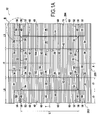
- Figure 1A represents a blank 12, which, when it is made up into a volume, allows a case body 14 as shown in figures 3 or 8A to be obtained.
- the blank 12 is achieved starting from a corrugated plate of polypropylene (for example 550 grams per square metre and a thickness of around 3 mm), cut out and marked by a standard press to indicate lines of folding.
- the folding is conceived to allow optimal resistance of the case 10 with the least possible material (here polypropylene).
- the structure of such a corrugated plate is formed by two exterior foils linked together by intermediate parallel walls. As shown in figures 1A and 1B , the plate is provided with flutes 15.
- the blank 12 is preferably cut out from such plate so that, once the case body 14 is formed, the flutes 15 extend transversally on the bottom part 16, horizontally on the short lateral sides 20a, 20b and vertically on the long lateral sides of the case body 14 (see figure 3 ) .
- the plate could also be devoid of flutes or the flutes could be oriented in the opposite direction.
- the blank 12 has an axial symmetry with respect to planes X and Y.
- the blank 12 comprises a central panel having a rectangular shape with a length L1 approximately twice as long as its width I1, intended to form the bottom part 16 of the case body 14.
- This central panel 16 comprises four assembling openings on each side of plane Y: one assembling opening 24 at each corner and one assembling opening 26 near the middle of each long edge 163, 164.
- These assembling openings 24, 26 are intended to receive assembling pins of adjacent cases (as will be described in more detail with reference to figure 8B ), and allow the drainage of melted ice and liquid from the fish contained in the box.
- first flank 281 comprising a main part 30 linked to the central panel 16 by a folding line 32, and two side legs 34, linked to both lateral sides of the main part 32 by folding lines 36.
- the length of the main part 30 is identical to the width I1 of the central panel 16, and its width I2 is identical to the height H1 desired for the case 10.
- the length L5 of each side leg 34 is less than half the length L1 of the central panel 16.
- the blank 12 further comprises, extending from the first long edge 163 of the central panel 16, a third flank 283 in two parts 38, 40.
- a first part 38 of the third flank 283 is connected to the first long edge 163 of the central panel 16 by a folding line 42, and the second part 40 is connected to said first part 38, on the side opposite to the central panel 16, by a folding line 44.
- the length of the first part 38 is equal to the length L1 of the long edge 163 of the central panel 16 to which it is connected, and its width 13, to the height H1 desired for the case.
- the second part 40 has approximately the same width 13 as the first part 38.
- said first part 38 and the main part 46 of said second part 40 are intended to form the first long side 18a of the case body 14.
- the second part 40 comprises a main part 46 having a length slightly smaller than L1, which is extended at each of its side ends by two flaps 48, 50.
- the first flaps 48 are linked to the main part 46 by folding lines 52.
- Each first flap 48 is provided with an assembling pin 54 at its one end to be oriented upwards once the case body 14 is formed.
- the blank 12 is pre-cut so as to form such an assembling pin 54 extending from the end of the each first flap 48 oriented towards the centre of the blank 12.
- Each first flap 48 is further provided with an opening (notch) 56 at its other end (i.e. at its free end).
- each opening 56 has a shape complementary to that of the assembling pins 54.
- the second flaps 50 are linked to the first flaps 48 at their sides opposite to the main part 46, by folding lines 58.
- each main part 46 As shown in figures 3 and 4 , four small lock tabs 60 are provided at the long free end of each main part 46.
- a fourth flank 284 similar to said third flank 283, extends from the second long edge 164 of the central panel 16 and is intended to form the second long side 18b of the case body 14.
- FIG. 1C shows a lid 22 adapted to cover and close the case body 14.
- the lid 22 is a rectangular corrugated plate made of polypropylene, having a length and width approximately equal to those L1, 11 of the case body 14, and a thickness of around 3 mm.
- the lid 22 comprises a hole 82 intended to cooperate with an assembling pin 54 of the case body 14.
- the lid 22 is provided with flutes 81 oriented in its transversal direction, for maximal stabilisation.
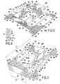
- the first and second flanks 281, 282 are first folded to 90° along the folding line 32 extending along each short edge 161, 162 of the central panel 16.
- the main parts 32 and the side legs 34 are all perpendicular to the central panel 16.
- the side legs 34 are again folded to 90° along the respective folding line 36 so as to be positioned above the long edges 163, 164 of the central panel 16.
- third and fourth flanks 283, 284 are folded over the said legs 34.
- the long sides 18a, 18b of the case thus comprise three layers (first part 38, second part 40 and legs 34 interposed therebetween), whereby the case is reinforced and able to carry heavy loads.
- the lock tabs 60 are eventually inserted in corresponding slits 62 of the central panel 16 (see figure 4 ), thus allowing all lateral sides of the case body 14 to be well maintained in position.
- each reinforcing wall 48 forms, with two adjacent lateral sides of the case body 14, a pillar with a triangular section. In the illustrated embodiment, each reinforcing wall 48 extends at an angle of 45° from each of the adjacent lateral sides of the case body 14. As shown on figure 3 , the assembling pin 54 of each reinforcing wall 46 protrudes from the case body 14 and the opening 56 of each reinforcing wall 48 is placed directly above an assembling opening 24 formed at a corner of the bottom part 16.
- the second flap 50 is folded along a main part 30, thus enhancing the short side 20a, 20b of the case body 14.
- the assembling pins 54 could be provided at the free end of the lateral sides 18a, 18b, 20a, 20b of the case body 14.
- an assembling pin forming a right angle and protruding from the top of two adjacent lateral sides 18a, 18b, 20a, 20b of the case body 14 could be formed at each edge (corner) of the case body 14.
- the lid 22 is preferably provided with notches at each of its corners so that it can be adapted on the top of the case body 14, allowing the assembling pins provided on top of each corner of the case body 14 to protrude.
- the case body 14, laid out on a conveyor 64 is filled, for example with fresh products such as fish 66. Due to the pressure applied by the fish 66 contained in the case body 14, each second flap 50 leans against a main part 30 of the case body 14 (see figure 3 ) and thus holds the adjacent reinforcing wall 48 in place.
- the second flap 50 is of sufficient length to avoid the products contained in the case becoming wedged between the second flap 50 and the main part 30.
- the length 16 of each second flap 50 is chosen so that the distance d1 (see figure 3 ) between the most adjacent long side of the case body 14 and the end of said second flap 50 is approximately equal to 2/3 of half of the width I1 of the case.
- the lateral sides 18a, 18b, 20a, 20b of the case body 14 buckle slightly under the effect of the weight of fish 66.
- the case body 14 is brought by the conveyor 64 towards a guide 68 having a funnel-shaped first portion 70 where its two lateral sides 68a, 68b converge and a second portion 72 where the distance separating said two lateral sides 68a, 68b is constant and equal to the width I1 of the case body 14.
- the long sides 18a, 18b of the case body 14 are set in an upright position and thus perfectly parallel to each other once the case body 14 arrives at the second portion 72 of the guide 68.
- the case body 14 is then brought by the conveyor 64 to a fixed work station 74. At this station, trap doors 76a, 76b, sliding upwards and running along the short sides 20a, 20b of the case body 14 position said short sides 20a, 20b perpendicularly to the bottom part 16 and the long sides 18a, 18b.
- the lid 22 is fixed to the case body 14 by hot air welding.
- a heat gun produces a jet of hot air that softens both the edges of the lid 22 and the top of the lateral sides 18a, 18b, 20a, 20b of the case body 14. Heating is carried out, for example, at a temperature of 270° and lasts 12 seconds.
- the lid 22 is then positioned on the top of the case body 14, each assembling pin 54 being introduced in a hole 82 of the lid 22 so as to finally protrude from the lid 22.
- the lid 22 has a length and width equal to that of the case body, its edges are precisely positioned on the free end of each lateral side of the case body 14. It should be noted that the lid 22 could also be provided with rims extending from its four edges.
- lid 22 is then attached to each lateral side of the case body 14 at a plurality of locations 86 regularly distributed on the top of each lateral side, by applying a punctual pressure with a pressing finger 89 to the softened edge of the lid 22, thus sealing the lid 22 and the case body 14.
- lid 22 is sealed with the first and second long sides 18a, 18b and with the first and second short sides 20a, 20b of the case body 14. That is, lid 22 is sealed with legs 34, and with parts 38 and 46 of the third and fourth flanks 283 and 284 at their folding line 44.
- the lid 22 is further sealed with the top of the main parts 30 of the first and second flanks 281, 282 and possibly with each second flap 50 of the third and fourth flanks 283, 284 leaning against said main parts 30.
- pressure can be applied by a caster moved gradually along the edges of the lid.
- the lid can be fixed in one step by application of a uniform pressure on the whole of its contour.
- each edge 90 (see figure 7 ) formed between two adjacent lateral sides 18a, 18b, 20a, 20b of the case 10
- said adjacent lateral sides are attached by bonding, for example by welding or adhesive bonding, over the entire height H1 of the case 10.
- bonding at an edge or each edge of the case 10 can be carried out only locally, at one or several locations over the height of the case 10.
- a case 10 as previously described can be provided with pre-cuts to enable the case to be easily opened.
- the lid 22 can be provided with at least two lines of pre-cuts forming a strip extending in the longitudinal direction of the case, preferably over the entire length thereof.
- the lid 22 can be further provided with a handle placed on this strip, near an end thereof, thus allowing easy opening of the case by pulling the handle, and tearing off the strip at least partially.
- the case can be opened by passing a hot wire along the interior face of a lateral side of the case, over almost the entire height of the case.
- the case can be opened by applying a hot wire with a uniform pressure against a lateral side of the case.
- a hot wire bent in a rectangular shape is applied against a lateral side of the case, thus forming in this lateral side a hole having the same rectangular form as the said hot wire.
- the box is preferably tilted during the opening process thereof, thus allowing the fish to slide to a corner or one side of the case when the hot wire cuts the opposite side.
- polypropylene when it is heated at a sufficient temperature, turns to vapour of CO 2 and water, which are not toxic. Consequently, if the polypropylene used for the case does not contain any additives, there is no risk of the content of the case becoming contaminated during the opening process (even if this content is agro alimentary products such as fish and even if the case is not tilted during the process).
- the assembling openings 24, 26 formed in the bottom part 16 of the case 10 allow the stacking of a plurality of such cases, in several layers, in a so-called crisscrossed or perpendicular pattern which will be described hereunder in more detail with reference to figures 8A, 8B and 9 .
- a lower case 10' and an upper case 10 such as described with reference to figures 1 to 7 , are placed perpendicularly to each other such that a corner of one case is superposed with a corner of the other case, thereby constituting a vertical column of two stacked pillars having a triangular section, each of them being formed by a reinforcing wall 48, 48' and the two adjacent lateral sides of the case body 14, 14'.
- a first assembling pin 54' of the lower case 10' is engaged in an assembling opening 26 of the upper case provided near the middle of one long side of the upper case.
- Figure 9 shows a pallet supporting two layers I, II of cases, each layer comprising three cases such as described with reference to figures 1 to 7 .
- each case preferably has a length L1 approximately twice as long as its width I1.
- the three cases 101', 102' and 103' thus form a parallelepiped the length of which is equal to the sum of the length and the width of a case, and the width of which is equal to the length of a case.
- the upper layer II has the same configuration than the lower layer I, but the two layers I, II are configured in a perpendicular pattern. That is, each case of the upper layer II is placed above at least one case of the lower layer I which is oriented perpendicularly thereto. As an example, the transversal case 103 of the upper layer is placed above and perpendicularly to the first and second layers 101', 102' of the lower layer I.
- This configuration enables the stacked cases to be imbricated, and the pallet to be stabilised thanks to the optimised repartition of the mechanical forces.
- each case of an upper layer covers entirely a case of the lower layer.
- each case of an upper layer faces and is parallel to the adjacent case of the lower layer.
- each pillar of each case is positioned facing a pillar of a case of an adjacent (upper or lower) layer.
- Cases positioned in a parallel pattern have a greater carrying capacity due to the said pillars. Once placed one above the other, the pillars form continuous reinforcing structures, and so maximize the absorption of the down force (due to the load of the upper cases).
- the stacking pattern of the cases on a pallet can be a combination of the above described parallel and perpendicular patterns.
- a stacking composed of several layers is provided with at least two superimposed layers configured in a parallel pattern and at least two superimposed layers configured in a perpendicular pattern.
- the stacking comprises three bottom layers of cases disposed in parallel pairs and forming a parallel pattern, and six upper layers of cases in a perpendicular pattern.
- the two stacking patterns that is by placing on the pallet at least two layers of cases disposed in a parallel pattern and further layers placed above in a perpendicular pattern, it is possible to obtain maximum absorption of the down force (load of the upper cases) and good stability of the stack.
- a case 10 as described previously can be delivered to the end user in the form of a cut out and pre marked plate.
- the user can more easily store plates of polypropylene than bulky cases.
- the cases can be formed starting from a standard machine used for example for the forming of cases out of cardboard. However, the use of a machine is not essential for forming the case as the folding of the case can be done manually.
- the case body 14 and the lid 22 are both formed from a corrugated plate of polypropylene having a grammage of 550 grams per square metre and a thickness of approximately 3 mm.
- the length L1 of the central panel 16 is 785 mm
- the width I1 of the central panel 16 is 390 mm
- the width I2 of the main part 30 (which is equal to the height desired for the case) is 165 mm
- the length L5 of each leg 34 is 345 mm
- the width I4 of reinforcing wall 48 (first flap) is 50 mm
- the width I6 of second flap 50 is 70 mm.
- a case having the afore-mentioned characteristics has a total weight of less than 850 g. Three such cases are able to carry a fully loaded pallet of 800 kg.
Landscapes
- Engineering & Computer Science (AREA)
- Mechanical Engineering (AREA)
- Stackable Containers (AREA)
Abstract
Description
- The present invention relates to the field of cases (i.e. crates or boxes) intended for the storage and transport of goods.
- More precisely, the present invention relates to a case for storing and transporting goods, and a process of forming, filling and closing such a case.
- The case and the process according to the present invention are particularly adapted to the packing and transport of fresh products, in particular sea products.
- Various types of cases intended for filling with products, for example agro alimentary products, and stacking, are already known. Usually, these cases are assembled by folding, starting from a blank, and covered with a lid. However, the known cases do not show sufficient characteristics of resistance for safely supporting heavy loads during long periods of time. The existing cases, in some circumstances, end up becoming twisted, yawned and distorted, and the pallets on which these cases are stored eventually buckle or even break. Because of the fragility of the stackings, the transfer of pallets supporting such cases proves to be very delicate.
- The purpose of the present invention is therefore to provide a case able to resist very heavy loads without becoming deformed, and thus adapted to stacking and transporting over long distances, and a method of forming, filling and closing such a case. In particular, a purpose of the invention is to provide a case which has the above mentioned advantages and, at the same time, is light and uses little material.
- According to a first aspect of the present invention, the above-mentioned purpose is achieved by a method of forming, filling and closing a case having a case body formed from one single blank and a lid, characterized in that it comprises the steps of
- folding the blank so as to give a shape to the case body such that it comprises a bottom part and four lateral sides,
- filling the case body,
- maintaining the lateral sides of the case body in parallel pairs,
- attaching the lid to the case body by bonding at at least one location at the top of each lateral side, and
- releasing the lateral sides of the case body.
- In the process according to the invention, a case body is formed by folding a blank, without the addition of exterior elements or material and without bonding. The pre-cuts and folding of the blank are chosen to provide the case body with sufficient rigidity to be self standing and to keep its global form at the time it is filled with products. Once the case body is filled, its lateral sides are temporarily maintained in position in parallel pairs by an exterior maintaining device. It should be noted that said lateral sides could be already maintained in position in parallel pairs by an exterior maintaining device when the case body is filled. A lid is then bonded on the free ends of the lateral sides of the case body. Contrary to known methods, the lid is thus attached to the case body before each pair of adjacent lateral sides of said case body are possibly attached by bonding. It can therefore be positioned much more precisely. In particular, the geometry of the case is not affected by possible defects occurring when fixing the edges of the case body. The case can thus be formed as a parallelepiped, the geometry of which is almost perfect. The case so formed constitutes a modular structure which is very resistant on all sides and particularly resistant to loads applied vertically on its top. The risks of distortion and deformation of the case under the effect of loads are thus reduced. Further, during storage, stacks of cases according to the present invention can be increased in height as the stability of the cases prevents collapsing. Furthermore, a pallet supporting stacked cases produced with the method according to the invention does not need to be coated to ensure stability.
- Preferably, the blank and the lid used for the present method are made of polypropylene. More preferably, the blank and the lid used for the present method are integrally made of polypropylene without the use of additives.
- Polypropylene has many advantages: It is both recyclable and recycled, which allows reducing its environmental impact, it is light, flexible and practical, and can be easily welded. Also, polypropylene is permeable to cold, which increases the benefit of cooled transport. Polypropylene being very resistant, the thickness of the sides, bottom and lid of the case can be reduced compared to cases made of less resistant materials such as polystyrene, and the over-all dimensions of the case are thus decreased. The reduced height of each pallet allows the lowering of its centre of gravity, which helps to prevent falling of the cases due to movement during the transport. The reduced over-all dimensions of the case further facilitate practicability thereof for the users.
- According to the present invention, bonding is to be understood as chemical bonding and, in particular, chemical bonding achieved either with or without additional material such as glue, for example.
- For instance, the lid can be attached to the case body by adhesive bonding using glue, which is currently the most widespread method in the field of packing.
- According to another example, the lid can be attached to the case body by hot air welding. Hot air welding is a simple and economic method, and it has a satisfactory environmental impact.
- According to still another example, the lid can be attached to the case body by ultrasonic welding which also has a limited environmental impact since it is very energy saving.
- In both cases (hot air welding and ultrasonic welding), provided that the case body and the lid are made in a recyclable material, for example polypropylene, the case can be 100% recyclable as no additional material (such as glue) is necessary.
- The fixing of the lid by adhesive bonding or welding brings rigidity to the case body which, as such, is rather flexible. It avoids the hooping of the case, and can ensure its inviolability.
- According to an aspect of the invention, the lid is attached to each lateral side of the case body at a plurality of locations distributed on the top of the lateral side. Therefore, residues of products remaining at the free end of the lateral sides of the case body after filling can easily be pushed and evacuated from between the points of fixing of the lid and do not obstruct closing.
- According to another aspect, the lid is attached continuously all along the top of each lateral side of the case body, so as to keep the case completely inviolable.
- According to an aspect of the invention, after the lid has been attached to the case body (or at the same time), at least two adjacent lateral sides of the case are attached together, by bonding, at their respective ends which are in contact and define an edge of the case. The adjacent lateral sides can be attached by bonding at one (or several) location(s) along the height of the edge of the case or can be attached together over the entire height thereof.
- The invention further concerns a case having a case body formed from one single blank by folding, with a bottom part and four lateral sides parallel in pairs, and a lid, characterized in that the lid is attached to the case body by bonding at at least one location of the top of each lateral side.
- The lid can be attached to the case body, for example by welding or adhesive bonding.
- Advantageously, the case body and the lid are made of polypropylene.
- In order to improve the resistance of the case, each corner of the case body delimitated by two adjacent lateral sides can be provided with a reinforcing wall having the same height as said lateral sides and forming a triangle with said lateral sides. The reinforcing wall forms with the two adjacent lateral sides of the case body, a pillar having a triangular section and extending over the entire height of the case.
- In order to make stacks of cases more stable, each corner of the case body can further be provided at its end facing the lid with an assembling pin, said assembling pin being engaged in an opening (i.e. a notch or hole) provided in the lid and protruding from the case so as to be engageable in a corresponding assembling opening provided in the bottom of an adjacent upper case. Each assembling pin can, for example, be situated at the end of a reinforcing wall as defined here above, or at the end of one lateral side (or two adjacent lateral sides) of the case body. The bottom part of the case body can comprise assembling openings for receiving the assembling pins of an adjacent lower case.
- According to an example, the case has a length approximately twice as long as its width. In this case, the bottom part of the case body preferably comprises at least one assembling opening at each corner and at least one assembling opening near the middle of each long lateral side, such that a plurality of cases can be superimposed perpendicularly to each other.
- A preferred embodiment of the case and method according to the present invention will now be described by way of example with reference to the accompanying drawings, in which:
-
Figure 1A represents a blank for forming a case according to the present invention; -
Figure 1B represents in detail a part of the blank offigure 1A intended to constitute a reinforcing wall at a corner of the case; -
Figure 1C represents a lid of a case according to the present invention; -
Figures 2 and 3 illustrate various stages of forming the case body starting from the blank offigure 1A ; -
Figure 4 represents in detail means for maintaining in position the lateral sides of the case body; -
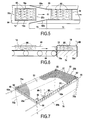
Figure 5 illustrates the step of maintaining the long sides of the case body in parallel pairs; -
Figure 6 illustrates the step of maintaining the short sides of the case body in parallel pairs; -
Figure 7 illustrates the step of attaching the lid to the case body at the top of each lateral side; -
Figure 8A and 8B illustrate the stacking of two cases formed according to the method illustrated onfigures 2 to 7 ; -
Figure 9 illustrates a stack of multiple cases according to the present invention, on a pallet; -
Figure 10 illustrates a plurality of cases according to the present invention, stacked on a pallet by using a combination of parallel and perpendicular stacking patterns. - An example of a
case 10 according to the invention will now be described with reference tofigures 1A to 10 . - As shown in
figure 8A , thecase 10, once formed, comprises acase body 14 having abottom part 16, a firstlong side 18a, a secondlong side 18b, a firstshort side 20a and a secondshort side 20b, and alid 22 adapted to cover and close saidcase body 14. In the illustrated example, thelid 22 is initially separated from thecase body 14. According to another embodiment of the invention, thelid 22 could be formed in one piece with thecase body 14. - In the present embodiment, the
case 10 is intended for the storage of fresh sea products such as fish. -
Figure 1A represents a blank 12, which, when it is made up into a volume, allows acase body 14 as shown infigures 3 or8A to be obtained. - The blank 12 is achieved starting from a corrugated plate of polypropylene (for example 550 grams per square metre and a thickness of around 3 mm), cut out and marked by a standard press to indicate lines of folding. The folding is conceived to allow optimal resistance of the
case 10 with the least possible material (here polypropylene). As already known, the structure of such a corrugated plate is formed by two exterior foils linked together by intermediate parallel walls. As shown infigures 1A and1B , the plate is provided withflutes 15. The blank 12 is preferably cut out from such plate so that, once thecase body 14 is formed, theflutes 15 extend transversally on thebottom part 16, horizontally on theshort lateral sides figure 3 ) . According to other embodiments, the plate could also be devoid of flutes or the flutes could be oriented in the opposite direction. - Generally, the blank 12 has an axial symmetry with respect to planes X and Y.
- As shown in
figure 1A , the blank 12 comprises a central panel having a rectangular shape with a length L1 approximately twice as long as its width I1, intended to form thebottom part 16 of thecase body 14. Thiscentral panel 16 comprises four assembling openings on each side of plane Y: one assemblingopening 24 at each corner and one assemblingopening 26 near the middle of eachlong edge openings figure 8B ), and allow the drainage of melted ice and liquid from the fish contained in the box. - Extending from the first
short edge 161 of saidcentral panel 16 is provided afirst flank 281 comprising amain part 30 linked to thecentral panel 16 by afolding line 32, and twoside legs 34, linked to both lateral sides of themain part 32 by foldinglines 36. The length of themain part 30 is identical to the width I1 of thecentral panel 16, and its width I2 is identical to the height H1 desired for thecase 10. The length L5 of eachside leg 34 is less than half the length L1 of thecentral panel 16. - A
second flank 282, similar to thefirst flank 281 described here above, extends from the secondshort edge 162 of thecentral panel 16. - The blank 12 further comprises, extending from the first
long edge 163 of thecentral panel 16, athird flank 283 in twoparts - A
first part 38 of thethird flank 283 is connected to the firstlong edge 163 of thecentral panel 16 by afolding line 42, and thesecond part 40 is connected to saidfirst part 38, on the side opposite to thecentral panel 16, by afolding line 44. The length of thefirst part 38 is equal to the length L1 of thelong edge 163 of thecentral panel 16 to which it is connected, and itswidth 13, to the height H1 desired for the case. Thesecond part 40 has approximately thesame width 13 as thefirst part 38. - Once folded back on one another, as described in more detail with reference to
figure 4 , saidfirst part 38 and themain part 46 of saidsecond part 40 are intended to form the firstlong side 18a of thecase body 14. - As shown on
figures 1A ,2 and 3 , thesecond part 40 comprises amain part 46 having a length slightly smaller than L1, which is extended at each of its side ends by twoflaps main part 46 by foldinglines 52. Eachfirst flap 48 is provided with an assemblingpin 54 at its one end to be oriented upwards once thecase body 14 is formed. In other words, the blank 12 is pre-cut so as to form such anassembling pin 54 extending from the end of the eachfirst flap 48 oriented towards the centre of the blank 12. Eachfirst flap 48 is further provided with an opening (notch) 56 at its other end (i.e. at its free end). Preferably, each opening 56 has a shape complementary to that of the assembling pins 54. The second flaps 50 are linked to thefirst flaps 48 at their sides opposite to themain part 46, by foldinglines 58. - As shown in
figures 3 and 4 , foursmall lock tabs 60 are provided at the long free end of eachmain part 46. - A
fourth flank 284, similar to saidthird flank 283, extends from the secondlong edge 164 of thecentral panel 16 and is intended to form the secondlong side 18b of thecase body 14. -
Figure 1C shows alid 22 adapted to cover and close thecase body 14. Thelid 22 is a rectangular corrugated plate made of polypropylene, having a length and width approximately equal to those L1, 11 of thecase body 14, and a thickness of around 3 mm. At each corner, thelid 22 comprises ahole 82 intended to cooperate with an assemblingpin 54 of thecase body 14. Thelid 22 is provided withflutes 81 oriented in its transversal direction, for maximal stabilisation. - The various stages of forming, filling and closing the
case 10 described previously will now be described with reference tofigures 2 to 7 . - As shown in
figure 2 , the first andsecond flanks folding line 32 extending along eachshort edge central panel 16. In this manner, themain parts 32 and theside legs 34 are all perpendicular to thecentral panel 16. Then, theside legs 34 are again folded to 90° along therespective folding line 36 so as to be positioned above thelong edges central panel 16. - As shown in
figure 3 , third andfourth flanks legs 34. Thelong sides first part 38,second part 40 andlegs 34 interposed therebetween), whereby the case is reinforced and able to carry heavy loads. - The
lock tabs 60 are eventually inserted in correspondingslits 62 of the central panel 16 (seefigure 4 ), thus allowing all lateral sides of thecase body 14 to be well maintained in position. - As shown on
figure 3 , thefirst flaps 48 of the third andfourth flank case body 14. Each reinforcingwall 48 forms, with two adjacent lateral sides of thecase body 14, a pillar with a triangular section. In the illustrated embodiment, each reinforcingwall 48 extends at an angle of 45° from each of the adjacent lateral sides of thecase body 14. As shown onfigure 3 , the assemblingpin 54 of each reinforcingwall 46 protrudes from thecase body 14 and theopening 56 of each reinforcingwall 48 is placed directly above an assemblingopening 24 formed at a corner of thebottom part 16. - The
second flap 50 is folded along amain part 30, thus enhancing theshort side case body 14. - It should be noted that according to another (not illustrated) embodiment, the assembling pins 54 could be provided at the free end of the
lateral sides case body 14. For example, an assembling pin forming a right angle and protruding from the top of two adjacentlateral sides case body 14 could be formed at each edge (corner) of thecase body 14. In this case, thelid 22 is preferably provided with notches at each of its corners so that it can be adapted on the top of thecase body 14, allowing the assembling pins provided on top of each corner of thecase body 14 to protrude. - As shown in
figure 5 , thecase body 14, laid out on aconveyor 64, is filled, for example with fresh products such asfish 66. Due to the pressure applied by thefish 66 contained in thecase body 14, eachsecond flap 50 leans against amain part 30 of the case body 14 (seefigure 3 ) and thus holds the adjacent reinforcingwall 48 in place. It should be noted that, preferably, thesecond flap 50 is of sufficient length to avoid the products contained in the case becoming wedged between thesecond flap 50 and themain part 30. Advantageously, thelength 16 of eachsecond flap 50 is chosen so that the distance d1 (seefigure 3 ) between the most adjacent long side of thecase body 14 and the end of saidsecond flap 50 is approximately equal to 2/3 of half of the width I1 of the case. - As shown on
figure 5 , thelateral sides case body 14 buckle slightly under the effect of the weight offish 66. - The
case body 14 is brought by theconveyor 64 towards aguide 68 having a funnel-shapedfirst portion 70 where its twolateral sides second portion 72 where the distance separating said twolateral sides case body 14. As shown infigure 5 , thelong sides case body 14 are set in an upright position and thus perfectly parallel to each other once thecase body 14 arrives at thesecond portion 72 of theguide 68. - The
case body 14 is then brought by theconveyor 64 to a fixedwork station 74. At this station,trap doors short sides case body 14 position saidshort sides bottom part 16 and thelong sides - As shown in
figure 7 , when thelateral sides case body 14 are all in parallel pairs, alid 22 is approached, manually or automatically, from the top of thecase body 14. - In the illustrated embodiment, the
lid 22 is fixed to thecase body 14 by hot air welding. - During a first stage (not shown on the figures), a heat gun produces a jet of hot air that softens both the edges of the
lid 22 and the top of thelateral sides case body 14. Heating is carried out, for example, at a temperature of 270° and lasts 12 seconds. - The
lid 22 is then positioned on the top of thecase body 14, each assemblingpin 54 being introduced in ahole 82 of thelid 22 so as to finally protrude from thelid 22. As thelid 22 has a length and width equal to that of the case body, its edges are precisely positioned on the free end of each lateral side of thecase body 14. It should be noted that thelid 22 could also be provided with rims extending from its four edges. - As shown on
figure 7 , thelid 22 is then attached to each lateral side of thecase body 14 at a plurality oflocations 86 regularly distributed on the top of each lateral side, by applying a punctual pressure with apressing finger 89 to the softened edge of thelid 22, thus sealing thelid 22 and thecase body 14. Finally,lid 22 is sealed with the first and secondlong sides short sides case body 14. That is,lid 22 is sealed withlegs 34, and withparts fourth flanks folding line 44. Thelid 22 is further sealed with the top of themain parts 30 of the first andsecond flanks second flap 50 of the third andfourth flanks main parts 30. - It should be noted that according to another example, pressure can be applied by a caster moved gradually along the edges of the lid. According to still another example, the lid can be fixed in one step by application of a uniform pressure on the whole of its contour.
- Once the
lid 22 has been fixed on thecase body 14, at each edge 90 (seefigure 7 ) formed between two adjacentlateral sides case 10, said adjacent lateral sides are attached by bonding, for example by welding or adhesive bonding, over the entire height H1 of thecase 10. According to another embodiment of the invention, only some pairs oflateral sides case 10 can be carried out only locally, at one or several locations over the height of thecase 10. - A
case 10 as previously described can be provided with pre-cuts to enable the case to be easily opened. For instance, thelid 22 can be provided with at least two lines of pre-cuts forming a strip extending in the longitudinal direction of the case, preferably over the entire length thereof. Advantageously, thelid 22 can be further provided with a handle placed on this strip, near an end thereof, thus allowing easy opening of the case by pulling the handle, and tearing off the strip at least partially. - According to another example, the case can be opened by passing a hot wire along the interior face of a lateral side of the case, over almost the entire height of the case.
- According to still another example, the case can be opened by applying a hot wire with a uniform pressure against a lateral side of the case. For instance, a hot wire bent in a rectangular shape is applied against a lateral side of the case, thus forming in this lateral side a hole having the same rectangular form as the said hot wire.
- In order to prevent any damage to the fish, the box is preferably tilted during the opening process thereof, thus allowing the fish to slide to a corner or one side of the case when the hot wire cuts the opposite side.
- It should be noted that polypropylene, when it is heated at a sufficient temperature, turns to vapour of CO2 and water, which are not toxic. Consequently, if the polypropylene used for the case does not contain any additives, there is no risk of the content of the case becoming contaminated during the opening process (even if this content is agro alimentary products such as fish and even if the case is not tilted during the process).
- The assembling
openings bottom part 16 of thecase 10 allow the stacking of a plurality of such cases, in several layers, in a so-called crisscrossed or perpendicular pattern which will be described hereunder in more detail with reference tofigures 8A, 8B and9 . - In the example illustrated on
figures 8A and 8B , a lower case 10' and anupper case 10 such as described with reference tofigures 1 to 7 , are placed perpendicularly to each other such that a corner of one case is superposed with a corner of the other case, thereby constituting a vertical column of two stacked pillars having a triangular section, each of them being formed by a reinforcingwall 48, 48' and the two adjacent lateral sides of thecase body 14, 14'. - As shown on
figure 8A , a first assembling pin 54' of the lower case 10' is engaged in an assemblingopening 26 of the upper case provided near the middle of one long side of the upper case. - As shown on
figure 8A and in more detail onfigure 8B , another assemblingpin 54" of the lower case 10', protruding from its lid 22', is placed adjacent a corner of theupper case 10. It can thus be engaged in an assemblingopening 24 of theupper case 10, and further in thecorresponding opening 56 of the reinforcingwall 48 which is positioned directly above said assemblingopening 24. - The cooperation between assembling
pins 54', 54" of the lower case 10' and assemblingopenings upper case 10 enables the relative position of the cases to be maintained, thus stabilizing the stack. -
Figure 9 shows a pallet supporting two layers I, II of cases, each layer comprising three cases such as described with reference tofigures 1 to 7 . - In the lower layer I, two cases 101', 102' are positioned so that their long sides are parallel to each other and a third transversal case 103' is placed perpendicularly to the said two cases 101', 102'. As previously indicated, each case preferably has a length L1 approximately twice as long as its width I1. The three cases 101', 102' and 103' thus form a parallelepiped the length of which is equal to the sum of the length and the width of a case, and the width of which is equal to the length of a case.
- The upper layer II has the same configuration than the lower layer I, but the two layers I, II are configured in a perpendicular pattern. That is, each case of the upper layer II is placed above at least one case of the lower layer I which is oriented perpendicularly thereto. As an example, the
transversal case 103 of the upper layer is placed above and perpendicularly to the first and second layers 101', 102' of the lower layer I. This configuration enables the stacked cases to be imbricated, and the pallet to be stabilised thanks to the optimised repartition of the mechanical forces. - The position of the assembling
openings figure 10 . According to such stacking pattern, each case of an upper layer covers entirely a case of the lower layer. In other words, each case of an upper layer faces and is parallel to the adjacent case of the lower layer. In this way, each pillar of each case is positioned facing a pillar of a case of an adjacent (upper or lower) layer. - Cases positioned in a parallel pattern have a greater carrying capacity due to the said pillars. Once placed one above the other, the pillars form continuous reinforcing structures, and so maximize the absorption of the down force (due to the load of the upper cases).
- According to an advantageous example shown in
figure 10 , the stacking pattern of the cases on a pallet can be a combination of the above described parallel and perpendicular patterns. In other words, a stacking composed of several layers is provided with at least two superimposed layers configured in a parallel pattern and at least two superimposed layers configured in a perpendicular pattern. In the example shown infigure 10 , the stacking comprises three bottom layers of cases disposed in parallel pairs and forming a parallel pattern, and six upper layers of cases in a perpendicular pattern. - By combining the two stacking patterns (that is by placing on the pallet at least two layers of cases disposed in a parallel pattern and further layers placed above in a perpendicular pattern, it is possible to obtain maximum absorption of the down force (load of the upper cases) and good stability of the stack.
- A
case 10 as described previously can be delivered to the end user in the form of a cut out and pre marked plate. The user can more easily store plates of polypropylene than bulky cases. The cases can be formed starting from a standard machine used for example for the forming of cases out of cardboard. However, the use of a machine is not essential for forming the case as the folding of the case can be done manually. - According to an example, the
case body 14 and thelid 22 are both formed from a corrugated plate of polypropylene having a grammage of 550 grams per square metre and a thickness of approximately 3 mm. The length L1 of thecentral panel 16 is 785 mm, the width I1 of thecentral panel 16 is 390 mm, the width I2 of the main part 30 (which is equal to the height desired for the case) is 165 mm, the length L5 of eachleg 34 is 345 mm, the width I4 of reinforcing wall 48 (first flap) is 50 mm and the width I6 ofsecond flap 50 is 70 mm. A case having the afore-mentioned characteristics has a total weight of less than 850 g. Three such cases are able to carry a fully loaded pallet of 800 kg.
Claims (15)
- Method of forming, filling and closing a case (10) having a case body (14) formed from one single blank (12) and a lid (22), characterized in that it comprises the steps of:- folding the blank (12) so as to give a shape to the case body (14) such that it comprises a bottom part (16) and four lateral sides (18a, 18b, 20a, 20b),- filling the case body (14),- maintaining the lateral sides (18a, 18b, 20a, 20b) in parallel pairs,- attaching the lid (22) to the case body by bonding at at least one location at the top of each lateral side (18a, 18b, 20a, 20b),- releasing the lateral sides (18a, 18b, 20a, 20b) of the case body (14).
- Method according to claim 1, further comprising, after attaching the lid (22) to the case body (14), the step of attaching together, by bonding, at least two adjacent lateral sides (18a, 18b, 20a, 20b) of the case (10) at their respective ends which are in contact and define an edge (90) of the case (10).
- Method according to claim 1 or 2, wherein the bonding is achieved by hot air welding.
- Method according to claim 1 or 2, wherein the bonding is achieved by ultrasonic welding.
- Method according to claim 1 or 2, wherein the bonding is achieved by adhesive bonding.
- Method according to any one of claims 1 to 5, wherein the lid (22) is attached to each lateral side (18a, 18b, 20a, 20b) of the case body (14) at a plurality of locations distributed on the top of the lateral side (18a, 18b, 20a, 20b).
- Case (10) obtained by the method according to any one of claims 1 to 6.
- Case (10) having a case body (14) formed from one single blank (12) by folding, with a bottom part (16) and four lateral sides (18a, 18b, 20a, 20b) parallel in pairs, and a lid (22), characterized in that the lid (22) is attached to the case body (14) by bonding at at least one location of the top of each lateral side (18a, 18b, 20a, 20b).
- Case (10) according to claim 8, wherein the case body (14) and the lid (22) are made of polypropylene.
- Case (10) according to claim 8 or 9, wherein each corner of said case body (14) delimitated by two adjacent lateral sides (18a, 18b, 20a, 20b) is provided with a reinforcing wall (48) having the same height as said lateral sides and forming a triangle with said lateral sides.
- Case (10) according to any one of claims 8 to 10, wherein each corner of the case body (14) is provided at its end facing the lid (22) with an assembling pin (54), said assembling pin (54) being engaged in an opening (82) provided in the lid (22) and protruding from the case (10) so as to be engageable in a corresponding assembling opening (24, 26) provided in the bottom of an adjacent upper case (10), and the bottom part (16) of the case body (14) comprises assembling openings (24, 26) for receiving the assembling pins (54) of an adjacent lower case (10).
- Case (10) according to claims 10 and 11, wherein each assembling pin (54) is provided at the end of a reinforcing wall (48).
- Case (10) according to any one of claims 8 to 12, having a length twice as long as its width.
- Case (10) according to claims 11 and 13, wherein the bottom part (16) of the case body (14) comprises at least one assembling opening (24) at each corner and at least one assembling opening (26) near the middle of each long lateral side (18a, 18b), such that a plurality of cases (10) can be superimposed perpendicularly to each other.
- Case according to any one of claims 8 to 14, wherein the lid (22) is separate from the case body (14).
Priority Applications (3)
| Application Number | Priority Date | Filing Date | Title |
|---|---|---|---|
| EP20100305586 EP2392519B8 (en) | 2010-06-03 | 2010-06-03 | Case and method of forming, filling and closing such case |
| DK10305586T DK2392519T3 (en) | 2010-06-03 | 2010-06-03 | Box and method for forming, filling and closing such a box |
| PCT/EP2011/059158 WO2011151424A1 (en) | 2010-06-03 | 2011-06-01 | Case and method of forming, filling and closing such case |
Applications Claiming Priority (1)
| Application Number | Priority Date | Filing Date | Title |
|---|---|---|---|
| EP20100305586 EP2392519B8 (en) | 2010-06-03 | 2010-06-03 | Case and method of forming, filling and closing such case |
Publications (3)
| Publication Number | Publication Date |
|---|---|
| EP2392519A1 true EP2392519A1 (en) | 2011-12-07 |
| EP2392519B1 EP2392519B1 (en) | 2013-04-17 |
| EP2392519B8 EP2392519B8 (en) | 2013-05-29 |
Family
ID=42668719
Family Applications (1)
| Application Number | Title | Priority Date | Filing Date |
|---|---|---|---|
| EP20100305586 Active EP2392519B8 (en) | 2010-06-03 | 2010-06-03 | Case and method of forming, filling and closing such case |
Country Status (3)
| Country | Link |
|---|---|
| EP (1) | EP2392519B8 (en) |
| DK (1) | DK2392519T3 (en) |
| WO (1) | WO2011151424A1 (en) |
Citations (5)
| Publication number | Priority date | Publication date | Assignee | Title |
|---|---|---|---|---|
| US3332208A (en) * | 1965-02-15 | 1967-07-25 | R A Jones & Company Inc | Method and machine for lidding cartons |
| FR2261199A1 (en) * | 1974-02-14 | 1975-09-12 | Barrez Ste Normande Carton Ond | Folded cardboard box with lid glued on - tear-open area on lid marked by line of perforations |
| NL1002381C2 (en) * | 1996-02-19 | 1997-08-20 | Golfkartonindustrie Oehermesoe | Box folded from flat sheet |
| WO2003016153A1 (en) * | 2001-08-21 | 2003-02-27 | Conagra Grocery Products Company | Stackable self-aligning container |
| US20040211824A1 (en) * | 2001-11-02 | 2004-10-28 | Conway Doyle A. | Stackable paperboard container |
-
2010
- 2010-06-03 EP EP20100305586 patent/EP2392519B8/en active Active
- 2010-06-03 DK DK10305586T patent/DK2392519T3/en active
-
2011
- 2011-06-01 WO PCT/EP2011/059158 patent/WO2011151424A1/en not_active Ceased
Patent Citations (5)
| Publication number | Priority date | Publication date | Assignee | Title |
|---|---|---|---|---|
| US3332208A (en) * | 1965-02-15 | 1967-07-25 | R A Jones & Company Inc | Method and machine for lidding cartons |
| FR2261199A1 (en) * | 1974-02-14 | 1975-09-12 | Barrez Ste Normande Carton Ond | Folded cardboard box with lid glued on - tear-open area on lid marked by line of perforations |
| NL1002381C2 (en) * | 1996-02-19 | 1997-08-20 | Golfkartonindustrie Oehermesoe | Box folded from flat sheet |
| WO2003016153A1 (en) * | 2001-08-21 | 2003-02-27 | Conagra Grocery Products Company | Stackable self-aligning container |
| US20040211824A1 (en) * | 2001-11-02 | 2004-10-28 | Conway Doyle A. | Stackable paperboard container |
Also Published As
| Publication number | Publication date |
|---|---|
| DK2392519T3 (en) | 2013-07-22 |
| EP2392519B1 (en) | 2013-04-17 |
| EP2392519B8 (en) | 2013-05-29 |
| WO2011151424A1 (en) | 2011-12-08 |
Similar Documents
| Publication | Publication Date | Title |
|---|---|---|
| US5203494A (en) | Stackable package | |
| CA2795701C (en) | Reinforced cross-laminated bulk container | |
| US9180996B2 (en) | Corrugated cardboard box with open-work flaps and set of blanks for obtaining same | |
| CN103619730B (en) | A kind of packaging of flat goods and its packaging method | |
| US9045250B2 (en) | One piece bulk bin having an automatically-erecting bottom and methods for constructing the same | |
| JPH02205546A (en) | Flexible packed article | |
| JP5648582B2 (en) | Packaging box | |
| WO2003006326A1 (en) | Economical, stackable container for retail goods | |
| CN106660655A (en) | Display tray with support column and apertures | |
| US20080245697A1 (en) | Packaging system for carrying an item, preferably bulky and/or heavy items, and method for using the same | |
| US5265797A (en) | Box construction | |
| US5267663A (en) | Collapsible shipping container | |
| CA2795773C (en) | Reinforced cross-laminated bulk container | |
| US9205947B1 (en) | Multi-component container with air cell end panel reinforcements | |
| EP2392519B1 (en) | Case and method of forming, filling and closing such case | |
| WO2018150087A1 (en) | Box for bag-in-box package | |
| EP2475581B1 (en) | Device for packing bulk products, especially for food | |
| JP2006213386A (en) | Delivery box | |
| CN112262077B (en) | Method for manufacturing package | |
| RU137745U1 (en) | BOX FOR PACKED PIECES (OPTIONS) | |
| RU117410U1 (en) | BOX FOR PLACING A PACKED PRODUCT (OPTIONS) AND A PALLET FOR THIS BOX | |
| RU107777U1 (en) | PACKAGING FOR PACKED OR PACKED IN CARGO BOXES (OPTIONS) | |
| EP4069600A1 (en) | Blank for forming a package and a package | |
| RU2483994C1 (en) | Case for placement of packaged product (versions) and tray for this case | |
| JP7471747B2 (en) | Laminated packaging |
Legal Events
| Date | Code | Title | Description |
|---|---|---|---|
| 17P | Request for examination filed |
Effective date: 20100603 |
|
| AK | Designated contracting states |
Kind code of ref document: A1 Designated state(s): AL AT BE BG CH CY CZ DE DK EE ES FI FR GB GR HR HU IE IS IT LI LT LU LV MC MK MT NL NO PL PT RO SE SI SK SM TR |
|
| AX | Request for extension of the european patent |
Extension state: BA ME RS |
|
| PUAI | Public reference made under article 153(3) epc to a published international application that has entered the european phase |
Free format text: ORIGINAL CODE: 0009012 |
|
| GRAP | Despatch of communication of intention to grant a patent |
Free format text: ORIGINAL CODE: EPIDOSNIGR1 |
|
| GRAS | Grant fee paid |
Free format text: ORIGINAL CODE: EPIDOSNIGR3 |
|
| GRAA | (expected) grant |
Free format text: ORIGINAL CODE: 0009210 |
|
| AK | Designated contracting states |
Kind code of ref document: B1 Designated state(s): AL AT BE BG CH CY CZ DE DK EE ES FI FR GB GR HR HU IE IS IT LI LT LU LV MC MK MT NL NO PL PT RO SE SI SK SM TR |
|
| REG | Reference to a national code |
Ref country code: GB Ref legal event code: FG4D |
|
| REG | Reference to a national code |
Ref country code: CH Ref legal event code: EP |
|
| RAP2 | Party data changed (patent owner data changed or rights of a patent transferred) |
Owner name: MIKO PLAST AS Owner name: LABEYRIE FINE FOODS |
|
| REG | Reference to a national code |
Ref country code: IE Ref legal event code: FG4D |
|
| REG | Reference to a national code |
Ref country code: AT Ref legal event code: REF Ref document number: 607134 Country of ref document: AT Kind code of ref document: T Effective date: 20130515 |
|
| REG | Reference to a national code |
Ref country code: DE Ref legal event code: R096 Ref document number: 602010006264 Country of ref document: DE Effective date: 20130613 |
|
| REG | Reference to a national code |
Ref country code: DK Ref legal event code: T3 |
|
| REG | Reference to a national code |
Ref country code: DE Ref legal event code: R081 Ref document number: 602010006264 Country of ref document: DE Owner name: LABEYRIE FINE FOODS, FR Free format text: FORMER OWNERS: FINANCIERE DE KIEL, CARNE, FR; MIKO PLAST AS, OSLO, NO Effective date: 20130605 Ref country code: DE Ref legal event code: R081 Ref document number: 602010006264 Country of ref document: DE Owner name: LABEYRIE FINE FOODS, FR Free format text: FORMER OWNER: FINANCIERE DE KIEL, MIKO PLAST AS, , NO Effective date: 20130605 Ref country code: DE Ref legal event code: R081 Ref document number: 602010006264 Country of ref document: DE Owner name: LABEYRIE FINE FOODS, FR Free format text: FORMER OWNER: LABEYRIE FINE FOODS, CAME, FR Effective date: 20130626 Ref country code: DE Ref legal event code: R081 Ref document number: 602010006264 Country of ref document: DE Owner name: MIKO PLAST AS, NO Free format text: FORMER OWNER: FINANCIERE DE KIEL, MIKO PLAST AS, , NO Effective date: 20130605 Ref country code: DE Ref legal event code: R081 Ref document number: 602010006264 Country of ref document: DE Owner name: MIKO PLAST AS, NO Free format text: FORMER OWNER: LABEYRIE FINE FOODS, CAME, FR Effective date: 20130626 |
|
| REG | Reference to a national code |
Ref country code: NO Ref legal event code: T2 Effective date: 20130417 |
|
| REG | Reference to a national code |
Ref country code: AT Ref legal event code: MK05 Ref document number: 607134 Country of ref document: AT Kind code of ref document: T Effective date: 20130417 |
|
| REG | Reference to a national code |
Ref country code: LT Ref legal event code: MG4D |
|
| REG | Reference to a national code |
Ref country code: NL Ref legal event code: VDEP Effective date: 20130417 |
|
| PG25 | Lapsed in a contracting state [announced via postgrant information from national office to epo] |
Ref country code: AT Free format text: LAPSE BECAUSE OF FAILURE TO SUBMIT A TRANSLATION OF THE DESCRIPTION OR TO PAY THE FEE WITHIN THE PRESCRIBED TIME-LIMIT Effective date: 20130417 Ref country code: LT Free format text: LAPSE BECAUSE OF FAILURE TO SUBMIT A TRANSLATION OF THE DESCRIPTION OR TO PAY THE FEE WITHIN THE PRESCRIBED TIME-LIMIT Effective date: 20130417 Ref country code: SE Free format text: LAPSE BECAUSE OF FAILURE TO SUBMIT A TRANSLATION OF THE DESCRIPTION OR TO PAY THE FEE WITHIN THE PRESCRIBED TIME-LIMIT Effective date: 20130417 Ref country code: SI Free format text: LAPSE BECAUSE OF FAILURE TO SUBMIT A TRANSLATION OF THE DESCRIPTION OR TO PAY THE FEE WITHIN THE PRESCRIBED TIME-LIMIT Effective date: 20130417 Ref country code: BE Free format text: LAPSE BECAUSE OF FAILURE TO SUBMIT A TRANSLATION OF THE DESCRIPTION OR TO PAY THE FEE WITHIN THE PRESCRIBED TIME-LIMIT Effective date: 20130417 Ref country code: ES Free format text: LAPSE BECAUSE OF FAILURE TO SUBMIT A TRANSLATION OF THE DESCRIPTION OR TO PAY THE FEE WITHIN THE PRESCRIBED TIME-LIMIT Effective date: 20130728 Ref country code: GR Free format text: LAPSE BECAUSE OF FAILURE TO SUBMIT A TRANSLATION OF THE DESCRIPTION OR TO PAY THE FEE WITHIN THE PRESCRIBED TIME-LIMIT Effective date: 20130718 Ref country code: PT Free format text: LAPSE BECAUSE OF FAILURE TO SUBMIT A TRANSLATION OF THE DESCRIPTION OR TO PAY THE FEE WITHIN THE PRESCRIBED TIME-LIMIT Effective date: 20130819 Ref country code: FI Free format text: LAPSE BECAUSE OF FAILURE TO SUBMIT A TRANSLATION OF THE DESCRIPTION OR TO PAY THE FEE WITHIN THE PRESCRIBED TIME-LIMIT Effective date: 20130417 |
|
| PG25 | Lapsed in a contracting state [announced via postgrant information from national office to epo] |
Ref country code: LV Free format text: LAPSE BECAUSE OF FAILURE TO SUBMIT A TRANSLATION OF THE DESCRIPTION OR TO PAY THE FEE WITHIN THE PRESCRIBED TIME-LIMIT Effective date: 20130417 Ref country code: CY Free format text: LAPSE BECAUSE OF FAILURE TO SUBMIT A TRANSLATION OF THE DESCRIPTION OR TO PAY THE FEE WITHIN THE PRESCRIBED TIME-LIMIT Effective date: 20130417 Ref country code: BG Free format text: LAPSE BECAUSE OF FAILURE TO SUBMIT A TRANSLATION OF THE DESCRIPTION OR TO PAY THE FEE WITHIN THE PRESCRIBED TIME-LIMIT Effective date: 20130717 Ref country code: HR Free format text: LAPSE BECAUSE OF FAILURE TO SUBMIT A TRANSLATION OF THE DESCRIPTION OR TO PAY THE FEE WITHIN THE PRESCRIBED TIME-LIMIT Effective date: 20130417 Ref country code: PL Free format text: LAPSE BECAUSE OF FAILURE TO SUBMIT A TRANSLATION OF THE DESCRIPTION OR TO PAY THE FEE WITHIN THE PRESCRIBED TIME-LIMIT Effective date: 20130417 |
|
| RAP2 | Party data changed (patent owner data changed or rights of a patent transferred) |
Owner name: LABEYRIE FINE FOODS |
|
| PG25 | Lapsed in a contracting state [announced via postgrant information from national office to epo] |
Ref country code: CZ Free format text: LAPSE BECAUSE OF FAILURE TO SUBMIT A TRANSLATION OF THE DESCRIPTION OR TO PAY THE FEE WITHIN THE PRESCRIBED TIME-LIMIT Effective date: 20130417 Ref country code: EE Free format text: LAPSE BECAUSE OF FAILURE TO SUBMIT A TRANSLATION OF THE DESCRIPTION OR TO PAY THE FEE WITHIN THE PRESCRIBED TIME-LIMIT Effective date: 20130417 Ref country code: SK Free format text: LAPSE BECAUSE OF FAILURE TO SUBMIT A TRANSLATION OF THE DESCRIPTION OR TO PAY THE FEE WITHIN THE PRESCRIBED TIME-LIMIT Effective date: 20130417 |
|
| PLBE | No opposition filed within time limit |
Free format text: ORIGINAL CODE: 0009261 |
|
| STAA | Information on the status of an ep patent application or granted ep patent |
Free format text: STATUS: NO OPPOSITION FILED WITHIN TIME LIMIT |
|
| PG25 | Lapsed in a contracting state [announced via postgrant information from national office to epo] |
Ref country code: RO Free format text: LAPSE BECAUSE OF FAILURE TO SUBMIT A TRANSLATION OF THE DESCRIPTION OR TO PAY THE FEE WITHIN THE PRESCRIBED TIME-LIMIT Effective date: 20130417 Ref country code: IT Free format text: LAPSE BECAUSE OF FAILURE TO SUBMIT A TRANSLATION OF THE DESCRIPTION OR TO PAY THE FEE WITHIN THE PRESCRIBED TIME-LIMIT Effective date: 20130417 Ref country code: NL Free format text: LAPSE BECAUSE OF FAILURE TO SUBMIT A TRANSLATION OF THE DESCRIPTION OR TO PAY THE FEE WITHIN THE PRESCRIBED TIME-LIMIT Effective date: 20130417 |
|
| 26N | No opposition filed |
Effective date: 20140120 |
|
| REG | Reference to a national code |
Ref country code: DE Ref legal event code: R097 Ref document number: 602010006264 Country of ref document: DE Effective date: 20140120 |
|
| REG | Reference to a national code |
Ref country code: DE Ref legal event code: R082 Ref document number: 602010006264 Country of ref document: DE Representative=s name: CBDL PATENTANWAELTE, DE |
|
| REG | Reference to a national code |
Ref country code: DE Ref legal event code: R082 Ref document number: 602010006264 Country of ref document: DE Representative=s name: CBDL PATENTANWAELTE, DE Effective date: 20140610 Ref country code: DE Ref legal event code: R081 Ref document number: 602010006264 Country of ref document: DE Owner name: LABEYRIE FINE FOODS, FR Free format text: FORMER OWNERS: LABEYRIE FINE FOODS, CAME, FR; MIKO PLAST AS, OSLO, NO Effective date: 20140610 Ref country code: DE Ref legal event code: R081 Ref document number: 602010006264 Country of ref document: DE Owner name: LABEYRIE FINE FOODS, FR Free format text: FORMER OWNER: LABEYRIE FINE FOODS, MIKO PLAST AS, , NO Effective date: 20140610 |
|
| PG25 | Lapsed in a contracting state [announced via postgrant information from national office to epo] |
Ref country code: SM Free format text: LAPSE BECAUSE OF FAILURE TO SUBMIT A TRANSLATION OF THE DESCRIPTION OR TO PAY THE FEE WITHIN THE PRESCRIBED TIME-LIMIT Effective date: 20130417 |
|
| PG25 | Lapsed in a contracting state [announced via postgrant information from national office to epo] |
Ref country code: TR Free format text: LAPSE BECAUSE OF FAILURE TO SUBMIT A TRANSLATION OF THE DESCRIPTION OR TO PAY THE FEE WITHIN THE PRESCRIBED TIME-LIMIT Effective date: 20130417 |
|
| PG25 | Lapsed in a contracting state [announced via postgrant information from national office to epo] |
Ref country code: MK Free format text: LAPSE BECAUSE OF FAILURE TO SUBMIT A TRANSLATION OF THE DESCRIPTION OR TO PAY THE FEE WITHIN THE PRESCRIBED TIME-LIMIT Effective date: 20130417 Ref country code: HU Free format text: LAPSE BECAUSE OF FAILURE TO SUBMIT A TRANSLATION OF THE DESCRIPTION OR TO PAY THE FEE WITHIN THE PRESCRIBED TIME-LIMIT; INVALID AB INITIO Effective date: 20100603 |
|
| REG | Reference to a national code |
Ref country code: CH Ref legal event code: PUEA Owner name: LABEYRIE FINE FOODS, FR Free format text: FORMER OWNER: MIKO PLAST AS, FR Ref country code: CH Ref legal event code: NV Representative=s name: MICHELI AND CIE SA, CH |
|
| REG | Reference to a national code |
Ref country code: GB Ref legal event code: 732E Free format text: REGISTERED BETWEEN 20160204 AND 20160210 |
|
| REG | Reference to a national code |
Ref country code: FR Ref legal event code: PLFP Year of fee payment: 7 |
|
| REG | Reference to a national code |
Ref country code: FR Ref legal event code: PLFP Year of fee payment: 8 |
|
| REG | Reference to a national code |
Ref country code: FR Ref legal event code: PLFP Year of fee payment: 9 |
|
| PG25 | Lapsed in a contracting state [announced via postgrant information from national office to epo] |
Ref country code: AL Free format text: LAPSE BECAUSE OF FAILURE TO SUBMIT A TRANSLATION OF THE DESCRIPTION OR TO PAY THE FEE WITHIN THE PRESCRIBED TIME-LIMIT Effective date: 20130417 |
|
| REG | Reference to a national code |
Ref country code: DE Ref legal event code: R082 Ref document number: 602010006264 Country of ref document: DE Representative=s name: CBDL PATENTANWAELTE GBR, DE Ref country code: DE Ref legal event code: R082 Ref document number: 602010006264 Country of ref document: DE Representative=s name: CBDL PATENTANWAELTE EGBR, DE |
|
| P01 | Opt-out of the competence of the unified patent court (upc) registered |
Effective date: 20230428 |
|
| PGFP | Annual fee paid to national office [announced via postgrant information from national office to epo] |
Ref country code: MC Payment date: 20250527 Year of fee payment: 16 |
|
| PGFP | Annual fee paid to national office [announced via postgrant information from national office to epo] |
Ref country code: DE Payment date: 20250617 Year of fee payment: 16 |
|
| PGFP | Annual fee paid to national office [announced via postgrant information from national office to epo] |
Ref country code: GB Payment date: 20250625 Year of fee payment: 16 Ref country code: DK Payment date: 20250527 Year of fee payment: 16 |
|
| PGFP | Annual fee paid to national office [announced via postgrant information from national office to epo] |
Ref country code: IS Payment date: 20250507 Year of fee payment: 16 Ref country code: NO Payment date: 20250530 Year of fee payment: 16 |
|
| PGFP | Annual fee paid to national office [announced via postgrant information from national office to epo] |
Ref country code: LU Payment date: 20250528 Year of fee payment: 16 |
|
| PGFP | Annual fee paid to national office [announced via postgrant information from national office to epo] |
Ref country code: FR Payment date: 20250617 Year of fee payment: 16 |
|
| PGFP | Annual fee paid to national office [announced via postgrant information from national office to epo] |
Ref country code: MT Payment date: 20250508 Year of fee payment: 16 |
|
| PGFP | Annual fee paid to national office [announced via postgrant information from national office to epo] |
Ref country code: IE Payment date: 20250521 Year of fee payment: 16 |
|
| PGFP | Annual fee paid to national office [announced via postgrant information from national office to epo] |
Ref country code: CH Payment date: 20250701 Year of fee payment: 16 |