EP2392479A1 - Pneumatic tire - Google Patents
Pneumatic tire Download PDFInfo
- Publication number
- EP2392479A1 EP2392479A1 EP10735662A EP10735662A EP2392479A1 EP 2392479 A1 EP2392479 A1 EP 2392479A1 EP 10735662 A EP10735662 A EP 10735662A EP 10735662 A EP10735662 A EP 10735662A EP 2392479 A1 EP2392479 A1 EP 2392479A1
- Authority
- EP
- European Patent Office
- Prior art keywords
- rubber layer
- tire
- tread rubber
- tread
- thickness
- Prior art date
- Legal status (The legal status is an assumption and is not a legal conclusion. Google has not performed a legal analysis and makes no representation as to the accuracy of the status listed.)
- Granted
Links
Images


Classifications
-
- B—PERFORMING OPERATIONS; TRANSPORTING
- B60—VEHICLES IN GENERAL
- B60C—VEHICLE TYRES; TYRE INFLATION; TYRE CHANGING; CONNECTING VALVES TO INFLATABLE ELASTIC BODIES IN GENERAL; DEVICES OR ARRANGEMENTS RELATED TO TYRES
- B60C11/00—Tyre tread bands; Tread patterns; Anti-skid inserts
-
- B—PERFORMING OPERATIONS; TRANSPORTING
- B60—VEHICLES IN GENERAL
- B60C—VEHICLE TYRES; TYRE INFLATION; TYRE CHANGING; CONNECTING VALVES TO INFLATABLE ELASTIC BODIES IN GENERAL; DEVICES OR ARRANGEMENTS RELATED TO TYRES
- B60C11/00—Tyre tread bands; Tread patterns; Anti-skid inserts
- B60C11/0041—Tyre tread bands; Tread patterns; Anti-skid inserts comprising different tread rubber layers
- B60C11/005—Tyre tread bands; Tread patterns; Anti-skid inserts comprising different tread rubber layers with cap and base layers
-
- B—PERFORMING OPERATIONS; TRANSPORTING
- B60—VEHICLES IN GENERAL
- B60C—VEHICLE TYRES; TYRE INFLATION; TYRE CHANGING; CONNECTING VALVES TO INFLATABLE ELASTIC BODIES IN GENERAL; DEVICES OR ARRANGEMENTS RELATED TO TYRES
- B60C11/00—Tyre tread bands; Tread patterns; Anti-skid inserts
- B60C11/03—Tread patterns
- B60C11/0306—Patterns comprising block rows or discontinuous ribs
- B60C11/0309—Patterns comprising block rows or discontinuous ribs further characterised by the groove cross-section
-
- B—PERFORMING OPERATIONS; TRANSPORTING
- B60—VEHICLES IN GENERAL
- B60C—VEHICLE TYRES; TYRE INFLATION; TYRE CHANGING; CONNECTING VALVES TO INFLATABLE ELASTIC BODIES IN GENERAL; DEVICES OR ARRANGEMENTS RELATED TO TYRES
- B60C11/00—Tyre tread bands; Tread patterns; Anti-skid inserts
- B60C11/03—Tread patterns
- B60C11/04—Tread patterns in which the raised area of the pattern consists only of continuous circumferential ribs, e.g. zig-zag
- B60C11/042—Tread patterns in which the raised area of the pattern consists only of continuous circumferential ribs, e.g. zig-zag further characterised by the groove cross-section
-
- B—PERFORMING OPERATIONS; TRANSPORTING
- B60—VEHICLES IN GENERAL
- B60C—VEHICLE TYRES; TYRE INFLATION; TYRE CHANGING; CONNECTING VALVES TO INFLATABLE ELASTIC BODIES IN GENERAL; DEVICES OR ARRANGEMENTS RELATED TO TYRES
- B60C11/00—Tyre tread bands; Tread patterns; Anti-skid inserts
- B60C11/0008—Tyre tread bands; Tread patterns; Anti-skid inserts characterised by the tread rubber
- B60C2011/0016—Physical properties or dimensions
- B60C2011/0025—Modulus or tan delta
-
- B—PERFORMING OPERATIONS; TRANSPORTING
- B60—VEHICLES IN GENERAL
- B60C—VEHICLE TYRES; TYRE INFLATION; TYRE CHANGING; CONNECTING VALVES TO INFLATABLE ELASTIC BODIES IN GENERAL; DEVICES OR ARRANGEMENTS RELATED TO TYRES
- B60C11/00—Tyre tread bands; Tread patterns; Anti-skid inserts
- B60C11/0008—Tyre tread bands; Tread patterns; Anti-skid inserts characterised by the tread rubber
- B60C2011/0016—Physical properties or dimensions
- B60C2011/0033—Thickness of the tread
-
- Y—GENERAL TAGGING OF NEW TECHNOLOGICAL DEVELOPMENTS; GENERAL TAGGING OF CROSS-SECTIONAL TECHNOLOGIES SPANNING OVER SEVERAL SECTIONS OF THE IPC; TECHNICAL SUBJECTS COVERED BY FORMER USPC CROSS-REFERENCE ART COLLECTIONS [XRACs] AND DIGESTS
- Y10—TECHNICAL SUBJECTS COVERED BY FORMER USPC
- Y10S—TECHNICAL SUBJECTS COVERED BY FORMER USPC CROSS-REFERENCE ART COLLECTIONS [XRACs] AND DIGESTS
- Y10S152/00—Resilient tires and wheels
- Y10S152/905—Tread composition
-
- Y—GENERAL TAGGING OF NEW TECHNOLOGICAL DEVELOPMENTS; GENERAL TAGGING OF CROSS-SECTIONAL TECHNOLOGIES SPANNING OVER SEVERAL SECTIONS OF THE IPC; TECHNICAL SUBJECTS COVERED BY FORMER USPC CROSS-REFERENCE ART COLLECTIONS [XRACs] AND DIGESTS
- Y10—TECHNICAL SUBJECTS COVERED BY FORMER USPC
- Y10T—TECHNICAL SUBJECTS COVERED BY FORMER US CLASSIFICATION
- Y10T152/00—Resilient tires and wheels
- Y10T152/10—Tires, resilient
- Y10T152/10495—Pneumatic tire or inner tube
Abstract
Description
- The present invention relates to a pneumatic tire for improving uneven wear resistance performance of a tread.
- Conventionally, in order to satisfy various kinds of performances at the same time, a pneumatic tire has adopted so-called cap/base structure in which a tread comprises two tread rubber layers.
- For example, JP2003-127613 describes a radial tire for a heavy load, in which rubber hardness of a cap rubber layer and a base rubber layer and their hardness difference are specified, the base rubber layer comprises a pair of base rubber pieces which are discontinuously disposed in the both sides of a tire equatorial plane, and the thickness of this base rubber piece is increased from the inner to outer side in the tire width direction so that wear resistance can be highly maintained and increase in temperature of the tread is restrained to improve durability.
- However, the base rubber layer of the above-mentioned radial tire for a heavy load comprises a pair of base rubber pieces which are discontinuously disposed in the both sides of the tire equatorial plane so that the cap rubber layer having higher hardness is in contact with a belt. Therefore, especially when wear is progressed, stress is concentrated in a center portion due to wear of a shoulder portion so that the tread is likely to be come off. In addition, sufficient measures as to uneven wear of the tread are not taken in this tire.
- It is, therefore, an object of the present invention is to provide a pneumatic tire for preventing a tread from coming off and for improving uneven wear resistance performance of the tread.
- The subject matter of the present invention is as follows.
- [1] A pneumatic tire comprising a carcass serving as a framework and toroidally extending between a pair of bead cores, a belt and a tread disposed on a radially outer side of the carcass, wherein
the tread comprises a plurality of tread rubber layers,
dynamic elasticity of the outer tread rubber layer located in a radially outermost side of the tire is higher than dynamic elasticity of the inner tread rubber layer located in a radially innermost side of the tire, and
a thickness of the inner tread rubber layer in a region including a tire equatorial plane is smaller than a thickness of the inner tread rubber layer in other regions. -
- [2] The pneumatic tire according to the above item [1], wherein the thickness of the inner tread rubber layer gradually increases from the tire equatorial plane toward a tread ground contact end.
-
- [3] The pneumatic tire according to the above item [1] or [2], wherein the inner tread rubber layer is continuously disposed in a tire width direction.
-
- [4] The pneumatic tire according to the above item [1] or [2], wherein a thickness of the inner tread rubber layer in an inner end portion in a tire width direction is smaller than a thickness of the inner tread rubber layer in other portions and
- the inner end portion in the tire width direction of the inner tread rubber layer is located 0.2W to 0.4W away from the tire equatorial plane assuming that a tread half width is W.
-
- [5] The pneumatic tire according to the above item [2], wherein a thickness of the inner tread rubber layer in an inner end portion in a tire width direction is smaller than a thickness of the inner tread rubber layer in other portions,
- the inner end portion in the tire width direction of the inner tread rubber layer is located 0.45W to 0.75W away from the tire equatorial plane assuming that a tread half width is W,
- an aspect ratio is not more than 55%, and
- a tire section width is not less than 350mm.
-
- [6] The pneumatic tire according to any one of the above items [1] to [5], wherein dynamic elasticity of the outer tread rubber layer is 8.0MPa to 20MPa and
- dynamic elasticity of the inner tread rubber layer is 1.0MPa to 7.0MPa.
-
- [7] The pneumatic tire according to any one of the above items [1] to [6], wherein
- assuming that a tread half width is W,
- a thickness d1 of the inner tread rubber layer at the tire equatorial plane, a thickness d2 of the inner tread rubber layer at a position of W/3 away from the tire equatorial plane, a thickness d3 of the inner tread rubber layer at a position of 2W/3 away from the tire equatorial plane, and a length d4 of a line passing across the inner tread rubber layer of a normal line of the carcass passing through the tread ground contact end satisfy the following expressions (1) to (4).
-


-
- [8] The pneumatic tire according to any one of the above items [1] to [7], wherein dynamic elasticity of the outer tread rubber layer is 1.5 to 3.5 times more than dynamic elasticity of the inner tread rubber layer at temperature of 25°C, at frequency of 52Hz and at strain of 2%.
- According to the present invention, a pneumatic tire for improving uneven wear resistance performance of a tread and durability of a belt can be provided.
-
- [
FIG. 1] FIG. 1 is a widthwise sectional view of a half portion of a pneumatic tire according to the first embodiment of the present invention. - [
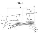
FIG. 2] FIG. 2 is a widthwise sectional view of a half portion of a pneumatic tire according to the second embodiment of the present invention. - [
FIG. 3] FIG. 3 is a widthwise sectional view of a half portion of a pneumatic tire according to the third embodiment of the present invention. - [
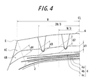
FIG. 4] FIG. 4 is a widthwise sectional view of a half portion of a conventional pneumatic tire. - [
FIG. 5] FIG. 5 is a view showing measurement results of uneven wear resistance performance of Example tire and Conventional Example tire. - Hereinafter, the present invention will be described in detail with reference to the drawings.
FIG. 1 is a widthwise sectional view of a half portion of a pneumatic tire according to the first embodiment of the present invention. A pneumatic tire of the invention comprises acarcass 2 serving as a framework and toroidally extending between a pair of bead cores, abelt 4 consisting of three belt layers in this example and atread 6 disposed on the radially outer side of thecarcass 2. These threebelt layers - The
tread 6 comprises a plurality of tread rubber layers, and more specifically, in this example, adopts so-called cap/base structure in which thetread 6 comprises two layers of acap rubber 6C which is an outer tread rubber layer located in the radially outermost side of the tire and abase rubber 6B which is an inner tread rubber layer located in the radially innermost side of the tire. Each of thecap rubber layer 6C and thebase rubber layer 6B is continuously disposed in tire width direction.
In case that thetread 6 comprises three or more tread rubber layers, dynamic elasticity of the outer tread rubber layer located in the radially outermost side of the tire and dynamic elasticity of the inner tread rubber layer located in the radially innermost side of the tire are specified and a thickness of the inner tread rubber layer is specified. It is preferable that thetread 6 comprises two layers of tread rubber layers as shown inFIG. 1 and the case when thetread 6 comprises two layers of tread rubber layers will be explained in the following. However, the present invention is not limited to this case. - It is important that dynamic elasticity of the
cap rubber layer 6C is higher than dynamic elasticity of thebase rubber layer 6B and a thickness of thebase rubber layer 6B in a region including the tire equatorial plane CL is smaller than a thickness of thebase rubber layer 6B in other regions. The reason for this will be explained below.
It is noted that "region including the tire equatorial plane CL (hereinafter, referred to as tread center portion)" means a region having W/3 in the tire width direction with the tire equatorial plane CL being as a center (W: tread half width) and "thickness of thebase rubber layer 6B in the tread center portion" means an average thickness of thebase rubber layer 6B in this region. In addition, when thebase rubber layer 6B is disposed in the tread center portion in the second and third embodiments described below, "thickness of thebase rubber layer 6B in the tread center portion" means an average thickness of thebase rubber layer 6B which is disposed in the region. - Conventionally, to satisfy both of wear resistance performance and belt durability performance, high durability rubber was disposed in the road surface side of the
tread 6 and low-heat-generating rubber was disposed in thebelt 4 side. However, it is known that ground contact pressure of a tire is the highest in a ground contact center portion, namely, the tread center portion and is gradually reduced toward the shoulder portion. Such uneven ground contact pressure causes uneven wear of thetread 6.
In the present invention, in addition to increasing dynamic elasticity of the high durability rubber disposed in the radially outer side of the tire and decreasing dynamic elasticity of the low-heat-generating rubber disposed in the radially inner side of the tire, by gradually increasing the ratio of the low-heat-generating rubber from the tread center portion toward the shoulder portion, width direction distribution in dynamic elasticity of thetread 6 is gained, which results in strain equalization of thetread 6 successfully.
In addition, by disposing soft and low-heat-generating rubber in the tread shoulder portion, even when wear is progressed, the ground contact pressure is kept even so that belt durability is also improved. - In addition, it is preferable that the thickness of the
base rubber layer 6B is gradually increased from the tire equatorial plane CL toward a tread ground contact end E and an interface between thecap rubber layer 6C and thebase rubber layer 6B is inclined in the radially outer side as it proceeds from the inner to outer side in the tire width direction except a range of a groove width of a groove formed in the tread.
As shown inFIG. 1 , the thickness of thebase rubber layer 6B may be the largest in the neighborhood of the tread ground contact end E and may be decreased in a region outside of the neighborhood of the tread ground contact end E in the tire width direction.
The term "neighborhood of the tread ground contact end E" as used herein means a region within a range of ±3.0cm with a normal line of thecarcass 2 being as a center, which passes through the tread ground contact end E. In addition, the tread ground contact end E is calculated when the tire is mounted on a regular rim and applied with the maximum load and the maximum air pressure (defined in JATMA, TRA, ETRTO). - As to specific dynamic elasticity of the tread rubber layer, it is preferable that dynamic elasticity of the
cap rubber layer 6C is 8.0MPa to 20.0MPa and dynamic elasticity of thebase rubber layer 6B is 1.0MPa to 7.0MPa.
When dynamic elasticity of thecap rubber layer 6C is less than 8.0MPa, the effect of reducing wear of thetread 6 may be insufficient. On the other hand, when dynamic elasticity of thecap rubber layer 6C is more than 20.0MPa, grip performance may be insufficient.
When dynamic elasticity of thebase rubber layer 6B is less than 1.0MPa, driving stability may be degraded. On the other hand, when dynamic elasticity of thebase rubber layer 6B is more than 7.0MPa, dynamic elasticity of thebase rubber layer 6B is insufficient and therefore may not sufficiently contribute to tread coming-off performance.
It is noted that dynamic elasticity (MPa) is measured at temperature of 25°C, at frequency of 52Hz and at strain of 2% with a spectrometer. - Assuming that a tread half width is W as shown in
FIG. 1 , it is preferable that a thickness d1 of thebase rubber layer 6B at the tire equatorial plane CL, a thickness d2 of thebase rubber layer 6B at a position of W/3 away from the tire equatorial plane CL, a thickness d3 of thebase rubber layer 6B at a position of 2W/3 away from the tire equatorial plane CL, and a length d4 of a line passing across thebase rubber layer 6B of a normal line of thecarcass 2 passing through the tread ground contact end E satisfy the following expressions (1) to (4).
It is noted that each of the thickness d1, d2 and d3 of thebase rubber layer 6B is measured in a direction perpendicular to the tire axis. -

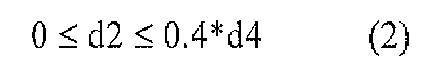


In case of d1 > 0.4*d4, d2 > 0.4*d4 and d3 > 1.1*d4, the effect of even wear may not be sufficient. In case of d4 >12mm, thebase rubber layer 6B may be exposed in the later stage of wear, which may cause uneven wear.
In case of d3 < 0.5*d4 or d4 < 3mm, the tread may generate large heat and have poor belt durability and poor durability to coming-off of the tread. - It is preferable that dynamic elasticity of the
cap rubber layer 6C is 1.5 to 3.5 times more than dynamic elasticity of thebase rubber layer 6B at temperature of 25°C, at frequency of 52Hz and at strain of 2%.
When the ratio of dynamic elasticity is less than 1.5, the difference in dynamic elasticity of the rubber is insufficient and dynamic elasticity change of the cap and base rubber layers in total may become insufficient.
On the other hand, when the ratio of dynamic elasticity is more than 3.5, production difficulty may arise. - Next, with reference to
FIG. 2 , the second embodiment of the present invention will be described.
The second embodiment is different from the first embodiment in that thebase rubber layer 6B is not continuous in the tire width direction but discontinuous in the tire equatorial plane CL. A thickness of thebase rubber layer 6B in an inner end portion in the tire width direction is smaller than a thickness of thebase rubber layer 6B in other portions and the inner end 6BE in the tire width direction of thebase rubber layer 6B is located 0.2W to 0.4W away from the tire equatorial plane CL.
It is noted that "inner end portion in the tire width direction of thebase rubber layer 6B" means a region from the inner end 6BE in the tire width direction of thebase rubber layer 6B to a point of 0.1 W away from the inner end 6BE in the widthwise outer direction of the tire and "thickness of thebase rubber layer 6B in the inner end portion in the tire width direction" means an average thickness of thebase rubber layer 6B which is disposed in the portion.
In this way, by not disposing thebase rubber layer 6B in the tire equatorial plane CL, as theentire tread 6 combining thecap rubber layer 6C and thebase rubber layer 6B, the difference of dynamic elasticity in the tread center portion and the tread shoulder portion becomes large so that uneven wear of the tread shoulder portion can be largely restrained. As described above, uneven wear of the tread shoulder portion is largely restrained so that the tread can be prevented from coming off even when wear of tread is progressed.
It is noted that the tread shoulder portion means a region between the tread ground contact end E and a circumferential groove which is firstly formed from the tread ground contact end E toward the tire widthwise inner direction. - When the inner end 6BE in the tire width direction of the
base rubber layer 6B is located less than 0.2W away from the tire equatorial plane CL, productivity of a tire may be reduced and the effect of restraining uneven wear of the tread shoulder portion cannot be sufficiently obtained. On the other hand, when the inner end 6BE in the tire width direction of thebase rubber layer 6B is located more than 0.4W away from the tire equatorial plane CL, dynamic elasticity of the tread shoulder portion and an intermediate block portion becomes excessively large, which may cause uneven wear of the intermediate block portion.
It is preferable that the inner end 6BE in the tire width direction of thebase rubber layer 6B is located more than 0.3W and less than 0.4W away from the tire equatorial plane CL. -
FIG. 3 is a widthwise sectional view of a half portion of a pneumatic tire according to the third embodiment of the present invention. In the third embodiment, a tire having an aspect ratio of not more than 55% and a tire section width of not less than 350mm is assumed. Same as the second embodiment, thebase rubber layer 6B is not continuous in the tire width direction but discontinuous in the tire equatorial plane CL. The inner end 6BE in the tire width direction of thebase rubber layer 6B is located 0.45W to 0.75W away from the tire equatorial plane CL. The thickness of thebase rubber layer 6B is gradually increased from the inner end 6BE toward the tread ground contact end E.
The effect that thebase rubber layer 6B is discontinuous in the tire equatorial plane CL and the reason for limiting the location of the inner end 6BE in the tire width direction of thebase rubber layer 6B are similar to those described with reference to the second embodiment. - Example pneumatic tires, Conventional Example pneumatic tire and Comparative Example pneumatic tire are experimentally produced under specifications to be described below and evaluated for uneven wear resistance performance, wear performance and heat generation property of the tread.
- Conventional Example tire comprises a tread consisting of one layer of tread rubber layer.
Example tires 1 to 17 and Comparative Example tire comprise acap rubber layer 6C and abase rubber 6B which is continuous in the tire width direction. Each of Example tires 1 to 17 is provided with abase rubber layer 6B having a small thickness in the tire equatorial plane CL and a large thickness in the shoulder side as shown inFIG. 1 while Comparative Example tire is provided with abase rubber layer 6B having an even thickness as shown inFIG. 4 .
Example tire 18 is not provided with abase rubber layer 6B in the tire equatorial plane CL as shown inFIG. 2 . The inner end 6BE in the tire width direction of thebase rubber layer 6B is located 1/3W away from the tire equatorial plane CL.
Example tire 19 is not provides with abase rubber layer 6B in the tire equatorial plane CL as shown inFIG. 3 . The inner end 6BE in the tire width direction of thebase rubber layer 6B is located 0.6W away from the tire equatorial plane CL.
Table 1 shows thicknesses d1 to d4 of thebase rubber layer 6B and dynamic elasticity of the rubber layers of each test tire. - Each test tire (Example tires 1 to 18 and Comparative Example tire: tire size of 275/80R22.5, Example tire 19: tire size of 445/50R22.5) is mounted on a rim of 7.50J to form a tire wheel, applied with the regular internal pressure, attached to a drum examination machine and then continuously travel at test speed of 70km/h to measure wear volume of the tread. The results are shown in index values with the wear resistance performance of Conventional Example tire being defined as 100 in Table 1. The larger value means the better wear resistance performance.
In addition, as for Conventional Example tire, Comparative Example tire and Example tire 1, wear volume difference between a center rib and a shoulder rib is measured. The measurement results of wear volume difference are shown inFIG. 5 .
It is noted that "regular internal pressure" refers to an air pressure corresponding to the maximum load capacity at applied size and ply rating defined in JATMA YEAR BOOK published in 2007 by the Japan Automobile Tyre Manufactures Association. - Each test tire (Example tires 1 to 18 and Comparative Example tire: tire size of275/80R22.5, Example tire 19: tire size of 445/50R22.5) is mounted on a rim of 7.50J to form a tire wheel, applied with the regular internal pressure, attached to a drum examination machine and then a drum examination at constant speed (65km/h) under step road condition is performed to measure running distance when the tire diameter is increased more than 5% due to inner separation. The results are shown in index values with the heat generation property of Conventional Example tire being defined as 100 in Table 1. The larger value means the better heat generation property.
Breaking energy of rubber is significantly decreased if temperature of the rubber is high. In addition, time degradation of breaking energy is increased if temperature of the rubber is high. The above-mentioned phenomenon by temperature can be indirectly caught as creep phenomenon (collapse) of the rubber. In case of a tire, since creep of rubber is seen in diameter growth, amount of diameter growth after a constant distance running can be a surrogate indicator of inner separation. Therefore, by measuring running distance when the tire diameter is increased more than 5% due to inner separation, it is possible to evaluate heat generation property. -
[Table 1] d1 d2 d3 d4 dynamic elasticity of cap rubber layer dynamic elasticity of base rubber layer Wear resistance performance Heat generating property Remarks Conventional Example tire - - - - 6.0 100 100 Comparative Example tire 5 5 5 5 8.0 4.0 150 150 Example tire 1 1 1 6 6 8.0 4.0 170 150 Example tire 2 1 1 6 6 20 4.0 200 150 (*1) Example tire 3 1 1 6 6 25 4.0 150 150 (*1) Example tire 4 1 1 6 6 8.0 1.0 150 150 (*2) Example tire 5 1 1 6 6 8.0 0.50 150 150 (*2) Example tire 6 1 1 6 6 8.0 7.0 150 150 (*3) Example tire 7 1 1 6 6 8.0 7.5 150 150 (*3) Example tire 8 1 1 3 3 8.0 4.0 150 130 (*3)(*4) Example tire 9 1 1 2.5 2.5 8.0 4.0 150 110 (*3)(*4) Example tire 10 1 1 12 12 8.0 4.0 150 170 (*5) Example tire 11 1 1 12.5 12.5 8.0 4.0 150 190 (*5) Example tire 12 1 1 3 6 8.0 4.0 150 140 (*6) Example tire 13 1 1 2.5 6 8.0 4.0 150 130 (*6) Example tire 14 1 1 6.6 6 8.0 4.0 150 160 (*5) Example tire 15 1 1 7 6 8.0 4.0 150 170 (*5) Example tire 16 2.4 2.4 6 6 8.0 4.0 150 150 (*3) Example tire 17 3 3 6 6 8.0 4.0 150 150 (*3) Example tire 18 0 0 6 6 8.0 4.0 190 150 (*7) Example tire 19 0 0 6 6 8.0 4.0 190 150 (*7) (*1): Production is difficult in comparison to Example tire 1.
(*2): Driving stability is degraded in comparison to Example tire 1,
(*3): Uneven wear performance is insufficiently improved in comparison to Example tire 1.
(*4): Heat generation property is degraded in comparison to Example tire 1.
(*5): Poor appearance due to exposure of the base rubber layer occurs in comparison to Example tire 1.
(*6): Heat generation property is slightly degraded in comparison to Example tire 1.
(*7): Productivity is slightly degraded in comparison to Example tire 1. - With reference to
FIG. 5 , in Conventional Example tire, the wear volume difference becomes 3.0mm at the time of running distance of 40,000km to finish the measurement. In Comparative Example tire, the wear volume difference becomes 2.5mm at the time of running distance of 48,000km to finish the measurement. In Example tire 1, the wear volume difference is not more than 0.5mm at the time of running distance of 60,000km.
Thus, it is found that, in Example tire 1, dynamic elasticity of the tread rubber is gradually decreased toward the shoulder portion in comparison to Conventional Example tire and Comparative Example tire so that uneven wear resistance is significantly improved. - It is found from Table 1 that, in Example tires and Comparative Example tire, dynamic elasticity of the tread rubber in the road surface side is higher than that of Conventional Example tire so that wear resistance performance is improved. It is also found that, by specifying the thickness of the base rubber layer, lower heat generation property is achieved in Example tires in comparison to Conventional Example tire.
- According to the present invention, the tread comprises a plurality of tread rubber layers and dynamic elasticity of each tread rubber layer is specified so that a pneumatic tire for improving uneven wear resistance performance, wear performance and heat generation property can be provided.
-
- 2
- carcass
- 4
- belt
- 4a, 4b, 4c
- inclined belt layer
- 6
- tread
- 6C
- cap rubber layer
- 6B
- base rubber layer
Claims (8)
- A pneumatic tire comprising a carcass serving as a framework and toroidally extending between a pair of bead cores, a belt and a tread disposed on a radially outer side of the carcass, wherein
the tread comprises a plurality of tread rubber layers,
dynamic elasticity of the outer tread rubber layer located in a radially outermost side of the tire is higher than dynamic elasticity of the inner tread rubber layer located in a radially innermost side of the tire, and
a thickness of the inner tread rubber layer in a region including a tire equatorial plane is smaller than a thickness of the inner tread rubber layer in other regions. - The pneumatic tire according to claim 1, wherein the thickness of the inner tread rubber layer gradually increases from the tire equatorial plane toward a tread ground contact end.
- The pneumatic tire according to claim 1 or 2, wherein the inner tread rubber layer is continuously disposed in a tire width direction.
- The pneumatic tire according to claim 1 or 2, wherein
a thickness of the inner tread rubber layer in an inner end portion in a tire width direction is smaller than a thickness of the inner tread rubber layer in other portions and
the inner end portion in the tire width direction of the inner tread rubber layer is located 0.2W to 0.4W away from the tire equatorial plane assuming that a tread half width is W. - The pneumatic tire according to claim 2, wherein
a thickness of the inner tread rubber layer in an inner end portion in a tire width direction is smaller than a thickness of the inner tread rubber layer in other portions,
the inner end portion in the tire width direction of the inner tread rubber layer is located 0.45W to 0.75W away from the tire equatorial plane assuming that a tread half width is W,
an aspect ratio is not more than 55%, and
a tire section width is not less than 350mm. - The pneumatic tire according to any one of claims 1 to 5, wherein
dynamic elasticity of the outer tread rubber layer is 8.0MPa to 20MPa and
dynamic elasticity of the inner tread rubber layer is 1.0MPa to 7.0MPa. - The pneumatic tire according to any one of claims 1 to 6, wherein
assuming that a tread half width is W,
a thickness d1 of the inner tread rubber layer at the tire equatorial plane, a thickness d2 of the inner tread rubber layer at a position of W/3 away from the tire equatorial plane, a thickness d3 of the inner tread rubber layer at a position of 2W/3 away from the tire equatorial plane, and a length d4 of a line passing across the inner tread rubber layer of a normal line of the carcass passing through the tread ground contact end satisfy the following expressions (1) to (4).
Note


- The pneumatic tire according to any one of claims 1 to 7, wherein dynamic elasticity of the outer tread rubber layer is 1.5 to 3.5 times more than dynamic elasticity of the inner tread rubber layer at temperature of 25°C, at frequency of 52Hz and at strain of 2%.
Applications Claiming Priority (2)
| Application Number | Priority Date | Filing Date | Title |
|---|---|---|---|
| JP2009018447 | 2009-01-29 | ||
| PCT/JP2010/000521 WO2010087190A1 (en) | 2009-01-29 | 2010-01-28 | Pneumatic tire |
Publications (3)
| Publication Number | Publication Date |
|---|---|
| EP2392479A1 true EP2392479A1 (en) | 2011-12-07 |
| EP2392479A4 EP2392479A4 (en) | 2013-08-14 |
| EP2392479B1 EP2392479B1 (en) | 2016-12-07 |
Family
ID=42395454
Family Applications (1)
| Application Number | Title | Priority Date | Filing Date |
|---|---|---|---|
| EP10735662.8A Not-in-force EP2392479B1 (en) | 2009-01-29 | 2010-01-28 | Pneumatic tire |
Country Status (7)
| Country | Link |
|---|---|
| US (1) | US8869849B2 (en) |
| EP (1) | EP2392479B1 (en) |
| JP (1) | JP5788677B2 (en) |
| CN (1) | CN102365181B (en) |
| BR (1) | BRPI1007486A2 (en) |
| RU (1) | RU2475369C1 (en) |
| WO (1) | WO2010087190A1 (en) |
Cited By (2)
| Publication number | Priority date | Publication date | Assignee | Title |
|---|---|---|---|---|
| EP2610076A4 (en) * | 2010-08-27 | 2014-05-14 | Bridgestone Corp | Pneumatic tire for two-wheeled vehicle |
| WO2019211565A1 (en) * | 2018-05-04 | 2019-11-07 | Compagnie Generale Des Etablissements Michelin | Tyre having improved properties of wear and rolling resistance |
Families Citing this family (6)
| Publication number | Priority date | Publication date | Assignee | Title |
|---|---|---|---|---|
| JP5703712B2 (en) * | 2010-11-22 | 2015-04-22 | 横浜ゴム株式会社 | Pneumatic tire |
| JP5845723B2 (en) * | 2011-08-26 | 2016-01-20 | 横浜ゴム株式会社 | Pneumatic tire |
| CN103935189A (en) * | 2014-04-14 | 2014-07-23 | 江苏通用科技股份有限公司 | Tire tread extrusion-molding structure applicable to mixed road conditions |
| WO2019145621A1 (en) * | 2018-01-25 | 2019-08-01 | Compagnie Generale Des Etablissements Michelin | Tyre with a tread sub-layer containing multiple materials |
| JP7031397B2 (en) * | 2018-03-16 | 2022-03-08 | 横浜ゴム株式会社 | Run flat tire |
| JP7156149B2 (en) * | 2019-04-15 | 2022-10-19 | 横浜ゴム株式会社 | pneumatic tire |
Citations (3)
| Publication number | Priority date | Publication date | Assignee | Title |
|---|---|---|---|---|
| GB2077671A (en) * | 1980-06-17 | 1981-12-23 | Bridgestone Tire Co Ltd | Pneumatic radial tyre |
| US5046542A (en) * | 1987-08-20 | 1991-09-10 | Bridgestone Corporation | Radial tires for construction vehicles including tread cap and divided tread base |
| JP2001071708A (en) * | 1999-09-02 | 2001-03-21 | Bridgestone Corp | Pneumatic tire |
Family Cites Families (13)
| Publication number | Priority date | Publication date | Assignee | Title |
|---|---|---|---|---|
| JPS6056603A (en) * | 1983-09-09 | 1985-04-02 | Bridgestone Corp | Motorcycle tyre being excellent in external disturbance absorption |
| JPS60255505A (en) * | 1984-05-31 | 1985-12-17 | Yokohama Rubber Co Ltd:The | Pneumatic tire |
| JPS61229602A (en) * | 1985-04-04 | 1986-10-13 | Ohtsu Tire & Rubber Co Ltd | Automobile tire tread |
| JP2889283B2 (en) | 1989-08-24 | 1999-05-10 | 株式会社ブリヂストン | High performance pneumatic tire |
| JP3869939B2 (en) * | 1998-07-01 | 2007-01-17 | 横浜ゴム株式会社 | Heavy duty pneumatic radial tire |
| JP3527673B2 (en) * | 1999-12-29 | 2004-05-17 | 住友ゴム工業株式会社 | Pneumatic tire |
| JP3564096B2 (en) * | 2001-10-25 | 2004-09-08 | 住友ゴム工業株式会社 | Radial tire for heavy loads |
| US7028734B2 (en) * | 2003-06-24 | 2006-04-18 | The Goodyear Tire & Rubber Company | Truck tire with cap/base construction tread |
| JP4410505B2 (en) * | 2003-07-15 | 2010-02-03 | 住友ゴム工業株式会社 | Heavy duty pneumatic tire |
| JP4523815B2 (en) * | 2004-08-26 | 2010-08-11 | 住友ゴム工業株式会社 | Heavy duty pneumatic tire and manufacturing method thereof |
| US7784510B2 (en) * | 2005-10-17 | 2010-08-31 | Sumitomo Rubber Industries, Ltd. | Heavy duty tire having cap and base rubber layers, belt cushion rubber and sidewall rubber |
| JP4707105B2 (en) | 2005-11-15 | 2011-06-22 | 株式会社ブリヂストン | Pneumatic tire |
| US20100154949A1 (en) * | 2007-05-16 | 2010-06-24 | Bridgestone Corporation | Pneumatic tire |
-
2010
- 2010-01-28 RU RU2011135790/11A patent/RU2475369C1/en not_active IP Right Cessation
- 2010-01-28 WO PCT/JP2010/000521 patent/WO2010087190A1/en active Application Filing
- 2010-01-28 EP EP10735662.8A patent/EP2392479B1/en not_active Not-in-force
- 2010-01-28 US US13/146,866 patent/US8869849B2/en active Active
- 2010-01-28 CN CN201080014214.4A patent/CN102365181B/en not_active Expired - Fee Related
- 2010-01-28 JP JP2010548434A patent/JP5788677B2/en not_active Expired - Fee Related
- 2010-01-28 BR BRPI1007486A patent/BRPI1007486A2/en active Search and Examination
Patent Citations (3)
| Publication number | Priority date | Publication date | Assignee | Title |
|---|---|---|---|---|
| GB2077671A (en) * | 1980-06-17 | 1981-12-23 | Bridgestone Tire Co Ltd | Pneumatic radial tyre |
| US5046542A (en) * | 1987-08-20 | 1991-09-10 | Bridgestone Corporation | Radial tires for construction vehicles including tread cap and divided tread base |
| JP2001071708A (en) * | 1999-09-02 | 2001-03-21 | Bridgestone Corp | Pneumatic tire |
Non-Patent Citations (1)
| Title |
|---|
| See also references of WO2010087190A1 * |
Cited By (3)
| Publication number | Priority date | Publication date | Assignee | Title |
|---|---|---|---|---|
| EP2610076A4 (en) * | 2010-08-27 | 2014-05-14 | Bridgestone Corp | Pneumatic tire for two-wheeled vehicle |
| WO2019211565A1 (en) * | 2018-05-04 | 2019-11-07 | Compagnie Generale Des Etablissements Michelin | Tyre having improved properties of wear and rolling resistance |
| FR3080797A1 (en) * | 2018-05-04 | 2019-11-08 | Compagnie Generale Des Etablissements Michelin | PNEUMATIC HAVING IMPROVED WEAR AND ROLL RESISTANCE PROPERTIES |
Also Published As
| Publication number | Publication date |
|---|---|
| EP2392479A4 (en) | 2013-08-14 |
| US20110277899A1 (en) | 2011-11-17 |
| JP5788677B2 (en) | 2015-10-07 |
| WO2010087190A1 (en) | 2010-08-05 |
| RU2475369C1 (en) | 2013-02-20 |
| CN102365181B (en) | 2014-05-21 |
| US8869849B2 (en) | 2014-10-28 |
| EP2392479B1 (en) | 2016-12-07 |
| BRPI1007486A2 (en) | 2016-02-16 |
| CN102365181A (en) | 2012-02-29 |
| JPWO2010087190A1 (en) | 2012-08-02 |
Similar Documents
| Publication | Publication Date | Title |
|---|---|---|
| EP2392479B1 (en) | Pneumatic tire | |
| US10569603B2 (en) | Pneumatic tire | |
| US20150165822A1 (en) | Pneumatic Tire | |
| US7036541B2 (en) | Pneumatic tire | |
| US10166819B2 (en) | Pneumatic tire | |
| US20140283965A1 (en) | Pneumatic tire | |
| US10239353B2 (en) | Pneumatic tire | |
| US20150298505A1 (en) | Pneumatic Tire | |
| US9987883B2 (en) | Pneumatic tire | |
| EP1466759B1 (en) | Heavy duty tire | |
| JP4618385B2 (en) | Pneumatic tire | |
| US9919564B2 (en) | Pneumatic tire | |
| US9950570B2 (en) | Pneumatic tire | |
| EP3360699B1 (en) | Heavy duty tire and and method for manufacturing the same | |
| US20160068018A1 (en) | Pneumatic Tire | |
| JP3808778B2 (en) | Heavy duty tire | |
| JP2016020111A (en) | Retreaded tire | |
| EP2998128B1 (en) | Pneumatic tire | |
| JP2006264595A (en) | Pneumatic tire | |
| US10272723B2 (en) | Pneumatic tire | |
| WO2016024390A1 (en) | Pneumatic tire | |
| JP5345876B2 (en) | Pneumatic tire | |
| JP2012180064A (en) | Pneumatic tire | |
| JP5275655B2 (en) | Pneumatic tire | |
| JP4577005B2 (en) | Pneumatic tire for light truck |
Legal Events
| Date | Code | Title | Description |
|---|---|---|---|
| PUAI | Public reference made under article 153(3) epc to a published international application that has entered the european phase |
Free format text: ORIGINAL CODE: 0009012 |
|
| 17P | Request for examination filed |
Effective date: 20110804 |
|
| AK | Designated contracting states |
Kind code of ref document: A1 Designated state(s): AT BE BG CH CY CZ DE DK EE ES FI FR GB GR HR HU IE IS IT LI LT LU LV MC MK MT NL NO PL PT RO SE SI SK SM TR |
|
| DAX | Request for extension of the european patent (deleted) | ||
| A4 | Supplementary search report drawn up and despatched |
Effective date: 20130716 |
|
| RIC1 | Information provided on ipc code assigned before grant |
Ipc: B60C 11/00 20060101AFI20130710BHEP |
|
| 17Q | First examination report despatched |
Effective date: 20150921 |
|
| GRAP | Despatch of communication of intention to grant a patent |
Free format text: ORIGINAL CODE: EPIDOSNIGR1 |
|
| INTG | Intention to grant announced |
Effective date: 20160621 |
|
| GRAS | Grant fee paid |
Free format text: ORIGINAL CODE: EPIDOSNIGR3 |
|
| GRAA | (expected) grant |
Free format text: ORIGINAL CODE: 0009210 |
|
| AK | Designated contracting states |
Kind code of ref document: B1 Designated state(s): AT BE BG CH CY CZ DE DK EE ES FI FR GB GR HR HU IE IS IT LI LT LU LV MC MK MT NL NO PL PT RO SE SI SK SM TR |
|
| REG | Reference to a national code |
Ref country code: GB Ref legal event code: FG4D |
|
| REG | Reference to a national code |
Ref country code: AT Ref legal event code: REF Ref document number: 851362 Country of ref document: AT Kind code of ref document: T Effective date: 20161215 Ref country code: CH Ref legal event code: EP |
|
| REG | Reference to a national code |
Ref country code: IE Ref legal event code: FG4D |
|
| REG | Reference to a national code |
Ref country code: DE Ref legal event code: R096 Ref document number: 602010038622 Country of ref document: DE |
|
| REG | Reference to a national code |
Ref country code: FR Ref legal event code: PLFP Year of fee payment: 8 |
|
| PG25 | Lapsed in a contracting state [announced via postgrant information from national office to epo] |
Ref country code: LV Free format text: LAPSE BECAUSE OF FAILURE TO SUBMIT A TRANSLATION OF THE DESCRIPTION OR TO PAY THE FEE WITHIN THE PRESCRIBED TIME-LIMIT Effective date: 20161207 |
|
| REG | Reference to a national code |
Ref country code: LT Ref legal event code: MG4D |
|
| REG | Reference to a national code |
Ref country code: NL Ref legal event code: MP Effective date: 20161207 |
|
| PG25 | Lapsed in a contracting state [announced via postgrant information from national office to epo] |
Ref country code: SE Free format text: LAPSE BECAUSE OF FAILURE TO SUBMIT A TRANSLATION OF THE DESCRIPTION OR TO PAY THE FEE WITHIN THE PRESCRIBED TIME-LIMIT Effective date: 20161207 Ref country code: LT Free format text: LAPSE BECAUSE OF FAILURE TO SUBMIT A TRANSLATION OF THE DESCRIPTION OR TO PAY THE FEE WITHIN THE PRESCRIBED TIME-LIMIT Effective date: 20161207 Ref country code: NO Free format text: LAPSE BECAUSE OF FAILURE TO SUBMIT A TRANSLATION OF THE DESCRIPTION OR TO PAY THE FEE WITHIN THE PRESCRIBED TIME-LIMIT Effective date: 20170307 Ref country code: GR Free format text: LAPSE BECAUSE OF FAILURE TO SUBMIT A TRANSLATION OF THE DESCRIPTION OR TO PAY THE FEE WITHIN THE PRESCRIBED TIME-LIMIT Effective date: 20170308 |
|
| REG | Reference to a national code |
Ref country code: AT Ref legal event code: MK05 Ref document number: 851362 Country of ref document: AT Kind code of ref document: T Effective date: 20161207 |
|
| PG25 | Lapsed in a contracting state [announced via postgrant information from national office to epo] |
Ref country code: HR Free format text: LAPSE BECAUSE OF FAILURE TO SUBMIT A TRANSLATION OF THE DESCRIPTION OR TO PAY THE FEE WITHIN THE PRESCRIBED TIME-LIMIT Effective date: 20161207 Ref country code: FI Free format text: LAPSE BECAUSE OF FAILURE TO SUBMIT A TRANSLATION OF THE DESCRIPTION OR TO PAY THE FEE WITHIN THE PRESCRIBED TIME-LIMIT Effective date: 20161207 Ref country code: ES Free format text: LAPSE BECAUSE OF FAILURE TO SUBMIT A TRANSLATION OF THE DESCRIPTION OR TO PAY THE FEE WITHIN THE PRESCRIBED TIME-LIMIT Effective date: 20161207 Ref country code: BE Free format text: LAPSE BECAUSE OF NON-PAYMENT OF DUE FEES Effective date: 20170131 |
|
| PG25 | Lapsed in a contracting state [announced via postgrant information from national office to epo] |
Ref country code: NL Free format text: LAPSE BECAUSE OF FAILURE TO SUBMIT A TRANSLATION OF THE DESCRIPTION OR TO PAY THE FEE WITHIN THE PRESCRIBED TIME-LIMIT Effective date: 20161207 |
|
| PG25 | Lapsed in a contracting state [announced via postgrant information from national office to epo] |
Ref country code: EE Free format text: LAPSE BECAUSE OF FAILURE TO SUBMIT A TRANSLATION OF THE DESCRIPTION OR TO PAY THE FEE WITHIN THE PRESCRIBED TIME-LIMIT Effective date: 20161207 Ref country code: SK Free format text: LAPSE BECAUSE OF FAILURE TO SUBMIT A TRANSLATION OF THE DESCRIPTION OR TO PAY THE FEE WITHIN THE PRESCRIBED TIME-LIMIT Effective date: 20161207 Ref country code: CZ Free format text: LAPSE BECAUSE OF FAILURE TO SUBMIT A TRANSLATION OF THE DESCRIPTION OR TO PAY THE FEE WITHIN THE PRESCRIBED TIME-LIMIT Effective date: 20161207 Ref country code: IS Free format text: LAPSE BECAUSE OF FAILURE TO SUBMIT A TRANSLATION OF THE DESCRIPTION OR TO PAY THE FEE WITHIN THE PRESCRIBED TIME-LIMIT Effective date: 20170407 Ref country code: RO Free format text: LAPSE BECAUSE OF FAILURE TO SUBMIT A TRANSLATION OF THE DESCRIPTION OR TO PAY THE FEE WITHIN THE PRESCRIBED TIME-LIMIT Effective date: 20161207 |
|
| PG25 | Lapsed in a contracting state [announced via postgrant information from national office to epo] |
Ref country code: SM Free format text: LAPSE BECAUSE OF FAILURE TO SUBMIT A TRANSLATION OF THE DESCRIPTION OR TO PAY THE FEE WITHIN THE PRESCRIBED TIME-LIMIT Effective date: 20161207 Ref country code: PT Free format text: LAPSE BECAUSE OF FAILURE TO SUBMIT A TRANSLATION OF THE DESCRIPTION OR TO PAY THE FEE WITHIN THE PRESCRIBED TIME-LIMIT Effective date: 20170407 Ref country code: BG Free format text: LAPSE BECAUSE OF FAILURE TO SUBMIT A TRANSLATION OF THE DESCRIPTION OR TO PAY THE FEE WITHIN THE PRESCRIBED TIME-LIMIT Effective date: 20170307 Ref country code: AT Free format text: LAPSE BECAUSE OF FAILURE TO SUBMIT A TRANSLATION OF THE DESCRIPTION OR TO PAY THE FEE WITHIN THE PRESCRIBED TIME-LIMIT Effective date: 20161207 Ref country code: PL Free format text: LAPSE BECAUSE OF FAILURE TO SUBMIT A TRANSLATION OF THE DESCRIPTION OR TO PAY THE FEE WITHIN THE PRESCRIBED TIME-LIMIT Effective date: 20161207 Ref country code: BE Free format text: LAPSE BECAUSE OF FAILURE TO SUBMIT A TRANSLATION OF THE DESCRIPTION OR TO PAY THE FEE WITHIN THE PRESCRIBED TIME-LIMIT Effective date: 20161207 |
|
| REG | Reference to a national code |
Ref country code: CH Ref legal event code: PL |
|
| REG | Reference to a national code |
Ref country code: DE Ref legal event code: R097 Ref document number: 602010038622 Country of ref document: DE |
|
| PG25 | Lapsed in a contracting state [announced via postgrant information from national office to epo] |
Ref country code: MC Free format text: LAPSE BECAUSE OF FAILURE TO SUBMIT A TRANSLATION OF THE DESCRIPTION OR TO PAY THE FEE WITHIN THE PRESCRIBED TIME-LIMIT Effective date: 20161207 |
|
| PLBE | No opposition filed within time limit |
Free format text: ORIGINAL CODE: 0009261 |
|
| STAA | Information on the status of an ep patent application or granted ep patent |
Free format text: STATUS: NO OPPOSITION FILED WITHIN TIME LIMIT |
|
| PG25 | Lapsed in a contracting state [announced via postgrant information from national office to epo] |
Ref country code: LI Free format text: LAPSE BECAUSE OF NON-PAYMENT OF DUE FEES Effective date: 20170131 Ref country code: CH Free format text: LAPSE BECAUSE OF NON-PAYMENT OF DUE FEES Effective date: 20170131 |
|
| REG | Reference to a national code |
Ref country code: IE Ref legal event code: MM4A |
|
| 26N | No opposition filed |
Effective date: 20170908 |
|
| GBPC | Gb: european patent ceased through non-payment of renewal fee |
Effective date: 20170307 |
|
| PG25 | Lapsed in a contracting state [announced via postgrant information from national office to epo] |
Ref country code: DK Free format text: LAPSE BECAUSE OF FAILURE TO SUBMIT A TRANSLATION OF THE DESCRIPTION OR TO PAY THE FEE WITHIN THE PRESCRIBED TIME-LIMIT Effective date: 20161207 Ref country code: LU Free format text: LAPSE BECAUSE OF NON-PAYMENT OF DUE FEES Effective date: 20170128 Ref country code: SI Free format text: LAPSE BECAUSE OF FAILURE TO SUBMIT A TRANSLATION OF THE DESCRIPTION OR TO PAY THE FEE WITHIN THE PRESCRIBED TIME-LIMIT Effective date: 20161207 |
|
| REG | Reference to a national code |
Ref country code: FR Ref legal event code: PLFP Year of fee payment: 9 |
|
| PG25 | Lapsed in a contracting state [announced via postgrant information from national office to epo] |
Ref country code: IE Free format text: LAPSE BECAUSE OF NON-PAYMENT OF DUE FEES Effective date: 20170128 Ref country code: GB Free format text: LAPSE BECAUSE OF NON-PAYMENT OF DUE FEES Effective date: 20170307 |
|
| PG25 | Lapsed in a contracting state [announced via postgrant information from national office to epo] |
Ref country code: MT Free format text: LAPSE BECAUSE OF NON-PAYMENT OF DUE FEES Effective date: 20170128 |
|
| PG25 | Lapsed in a contracting state [announced via postgrant information from national office to epo] |
Ref country code: HU Free format text: LAPSE BECAUSE OF FAILURE TO SUBMIT A TRANSLATION OF THE DESCRIPTION OR TO PAY THE FEE WITHIN THE PRESCRIBED TIME-LIMIT; INVALID AB INITIO Effective date: 20100128 |
|
| PG25 | Lapsed in a contracting state [announced via postgrant information from national office to epo] |
Ref country code: CY Free format text: LAPSE BECAUSE OF NON-PAYMENT OF DUE FEES Effective date: 20161207 |
|
| PG25 | Lapsed in a contracting state [announced via postgrant information from national office to epo] |
Ref country code: MK Free format text: LAPSE BECAUSE OF FAILURE TO SUBMIT A TRANSLATION OF THE DESCRIPTION OR TO PAY THE FEE WITHIN THE PRESCRIBED TIME-LIMIT Effective date: 20161207 |
|
| PG25 | Lapsed in a contracting state [announced via postgrant information from national office to epo] |
Ref country code: TR Free format text: LAPSE BECAUSE OF FAILURE TO SUBMIT A TRANSLATION OF THE DESCRIPTION OR TO PAY THE FEE WITHIN THE PRESCRIBED TIME-LIMIT Effective date: 20161207 |
|
| PGFP | Annual fee paid to national office [announced via postgrant information from national office to epo] |
Ref country code: DE Payment date: 20200121 Year of fee payment: 11 Ref country code: IT Payment date: 20200131 Year of fee payment: 11 |
|
| PGFP | Annual fee paid to national office [announced via postgrant information from national office to epo] |
Ref country code: FR Payment date: 20200121 Year of fee payment: 11 |
|
| REG | Reference to a national code |
Ref country code: DE Ref legal event code: R119 Ref document number: 602010038622 Country of ref document: DE |
|
| PG25 | Lapsed in a contracting state [announced via postgrant information from national office to epo] |
Ref country code: FR Free format text: LAPSE BECAUSE OF NON-PAYMENT OF DUE FEES Effective date: 20210131 |
|
| PG25 | Lapsed in a contracting state [announced via postgrant information from national office to epo] |
Ref country code: DE Free format text: LAPSE BECAUSE OF NON-PAYMENT OF DUE FEES Effective date: 20210803 |
|
| PG25 | Lapsed in a contracting state [announced via postgrant information from national office to epo] |
Ref country code: IT Free format text: LAPSE BECAUSE OF NON-PAYMENT OF DUE FEES Effective date: 20210128 |