EP2392451A2 - Transfer apparatus for a line end of a folder-gluer - Google Patents
Transfer apparatus for a line end of a folder-gluer Download PDFInfo
- Publication number
- EP2392451A2 EP2392451A2 EP20110168176 EP11168176A EP2392451A2 EP 2392451 A2 EP2392451 A2 EP 2392451A2 EP 20110168176 EP20110168176 EP 20110168176 EP 11168176 A EP11168176 A EP 11168176A EP 2392451 A2 EP2392451 A2 EP 2392451A2
- Authority
- EP
- European Patent Office
- Prior art keywords
- rotation
- transfer
- boxes
- base frame
- belts
- Prior art date
- Legal status (The legal status is an assumption and is not a legal conclusion. Google has not performed a legal analysis and makes no representation as to the accuracy of the status listed.)
- Granted
Links
Images



Classifications
-
- B—PERFORMING OPERATIONS; TRANSPORTING
- B65—CONVEYING; PACKING; STORING; HANDLING THIN OR FILAMENTARY MATERIAL
- B65G—TRANSPORT OR STORAGE DEVICES, e.g. CONVEYORS FOR LOADING OR TIPPING, SHOP CONVEYOR SYSTEMS OR PNEUMATIC TUBE CONVEYORS
- B65G47/00—Article or material-handling devices associated with conveyors; Methods employing such devices
- B65G47/22—Devices influencing the relative position or the attitude of articles during transit by conveyors
- B65G47/24—Devices influencing the relative position or the attitude of articles during transit by conveyors orientating the articles
- B65G47/244—Devices influencing the relative position or the attitude of articles during transit by conveyors orientating the articles by turning them about an axis substantially perpendicular to the conveying plane
-
- B—PERFORMING OPERATIONS; TRANSPORTING
- B65—CONVEYING; PACKING; STORING; HANDLING THIN OR FILAMENTARY MATERIAL
- B65H—HANDLING THIN OR FILAMENTARY MATERIAL, e.g. SHEETS, WEBS, CABLES
- B65H11/00—Feed tables
- B65H11/002—Feed tables incorporating transport belts
-
- B—PERFORMING OPERATIONS; TRANSPORTING
- B65—CONVEYING; PACKING; STORING; HANDLING THIN OR FILAMENTARY MATERIAL
- B65H—HANDLING THIN OR FILAMENTARY MATERIAL, e.g. SHEETS, WEBS, CABLES
- B65H15/00—Overturning articles
- B65H15/016—Overturning articles employing rotary or reciprocating elements supporting transport means
-
- B—PERFORMING OPERATIONS; TRANSPORTING
- B65—CONVEYING; PACKING; STORING; HANDLING THIN OR FILAMENTARY MATERIAL
- B65H—HANDLING THIN OR FILAMENTARY MATERIAL, e.g. SHEETS, WEBS, CABLES
- B65H29/00—Delivering or advancing articles from machines; Advancing articles to or into piles
- B65H29/12—Delivering or advancing articles from machines; Advancing articles to or into piles by means of the nip between two, or between two sets of, moving tapes or bands or rollers
-
- B—PERFORMING OPERATIONS; TRANSPORTING
- B65—CONVEYING; PACKING; STORING; HANDLING THIN OR FILAMENTARY MATERIAL
- B65H—HANDLING THIN OR FILAMENTARY MATERIAL, e.g. SHEETS, WEBS, CABLES
- B65H31/00—Pile receivers
- B65H31/30—Arrangements for removing completed piles
- B65H31/3027—Arrangements for removing completed piles by the nip between moving belts or rollers
-
- B—PERFORMING OPERATIONS; TRANSPORTING
- B65—CONVEYING; PACKING; STORING; HANDLING THIN OR FILAMENTARY MATERIAL
- B65H—HANDLING THIN OR FILAMENTARY MATERIAL, e.g. SHEETS, WEBS, CABLES
- B65H5/00—Feeding articles separated from piles; Feeding articles to machines
- B65H5/02—Feeding articles separated from piles; Feeding articles to machines by belts or chains, e.g. between belts or chains
- B65H5/021—Feeding articles separated from piles; Feeding articles to machines by belts or chains, e.g. between belts or chains by belts
- B65H5/023—Feeding articles separated from piles; Feeding articles to machines by belts or chains, e.g. between belts or chains by belts between a pair of belts forming a transport nip
-
- B—PERFORMING OPERATIONS; TRANSPORTING
- B31—MAKING ARTICLES OF PAPER, CARDBOARD OR MATERIAL WORKED IN A MANNER ANALOGOUS TO PAPER; WORKING PAPER, CARDBOARD OR MATERIAL WORKED IN A MANNER ANALOGOUS TO PAPER
- B31B—MAKING CONTAINERS OF PAPER, CARDBOARD OR MATERIAL WORKED IN A MANNER ANALOGOUS TO PAPER
- B31B50/00—Making rigid or semi-rigid containers, e.g. boxes or cartons
- B31B50/74—Auxiliary operations
- B31B50/92—Delivering
-
- B—PERFORMING OPERATIONS; TRANSPORTING
- B31—MAKING ARTICLES OF PAPER, CARDBOARD OR MATERIAL WORKED IN A MANNER ANALOGOUS TO PAPER; WORKING PAPER, CARDBOARD OR MATERIAL WORKED IN A MANNER ANALOGOUS TO PAPER
- B31B—MAKING CONTAINERS OF PAPER, CARDBOARD OR MATERIAL WORKED IN A MANNER ANALOGOUS TO PAPER
- B31B50/00—Making rigid or semi-rigid containers, e.g. boxes or cartons
- B31B50/74—Auxiliary operations
- B31B50/92—Delivering
- B31B50/98—Delivering in stacks or bundles
-
- B—PERFORMING OPERATIONS; TRANSPORTING
- B65—CONVEYING; PACKING; STORING; HANDLING THIN OR FILAMENTARY MATERIAL
- B65G—TRANSPORT OR STORAGE DEVICES, e.g. CONVEYORS FOR LOADING OR TIPPING, SHOP CONVEYOR SYSTEMS OR PNEUMATIC TUBE CONVEYORS
- B65G15/00—Conveyors having endless load-conveying surfaces, i.e. belts and like continuous members, to which tractive effort is transmitted by means other than endless driving elements of similar configuration
- B65G15/10—Conveyors having endless load-conveying surfaces, i.e. belts and like continuous members, to which tractive effort is transmitted by means other than endless driving elements of similar configuration comprising two or more co-operating endless surfaces with parallel longitudinal axes, or a multiplicity of parallel elements, e.g. ropes defining an endless surface
- B65G15/12—Conveyors having endless load-conveying surfaces, i.e. belts and like continuous members, to which tractive effort is transmitted by means other than endless driving elements of similar configuration comprising two or more co-operating endless surfaces with parallel longitudinal axes, or a multiplicity of parallel elements, e.g. ropes defining an endless surface with two or more endless belts
- B65G15/14—Conveyors having endless load-conveying surfaces, i.e. belts and like continuous members, to which tractive effort is transmitted by means other than endless driving elements of similar configuration comprising two or more co-operating endless surfaces with parallel longitudinal axes, or a multiplicity of parallel elements, e.g. ropes defining an endless surface with two or more endless belts the load being conveyed between the belts
-
- B—PERFORMING OPERATIONS; TRANSPORTING
- B65—CONVEYING; PACKING; STORING; HANDLING THIN OR FILAMENTARY MATERIAL
- B65G—TRANSPORT OR STORAGE DEVICES, e.g. CONVEYORS FOR LOADING OR TIPPING, SHOP CONVEYOR SYSTEMS OR PNEUMATIC TUBE CONVEYORS
- B65G2201/00—Indexing codes relating to handling devices, e.g. conveyors, characterised by the type of product or load being conveyed or handled
- B65G2201/02—Articles
- B65G2201/0214—Articles of special size, shape or weigh
- B65G2201/022—Flat
-
- B—PERFORMING OPERATIONS; TRANSPORTING
- B65—CONVEYING; PACKING; STORING; HANDLING THIN OR FILAMENTARY MATERIAL
- B65G—TRANSPORT OR STORAGE DEVICES, e.g. CONVEYORS FOR LOADING OR TIPPING, SHOP CONVEYOR SYSTEMS OR PNEUMATIC TUBE CONVEYORS
- B65G47/00—Article or material-handling devices associated with conveyors; Methods employing such devices
- B65G47/22—Devices influencing the relative position or the attitude of articles during transit by conveyors
- B65G47/24—Devices influencing the relative position or the attitude of articles during transit by conveyors orientating the articles
- B65G47/248—Devices influencing the relative position or the attitude of articles during transit by conveyors orientating the articles by turning over or inverting them
- B65G47/252—Devices influencing the relative position or the attitude of articles during transit by conveyors orientating the articles by turning over or inverting them about an axis substantially perpendicular to the conveying direction
-
- B—PERFORMING OPERATIONS; TRANSPORTING
- B65—CONVEYING; PACKING; STORING; HANDLING THIN OR FILAMENTARY MATERIAL
- B65H—HANDLING THIN OR FILAMENTARY MATERIAL, e.g. SHEETS, WEBS, CABLES
- B65H2301/00—Handling processes for sheets or webs
- B65H2301/30—Orientation, displacement, position of the handled material
- B65H2301/33—Modifying, selecting, changing orientation
- B65H2301/332—Turning, overturning
- B65H2301/3321—Turning, overturning kinetic therefor
- B65H2301/33214—Turning, overturning kinetic therefor about an axis perpendicular to the direction of displacement and parallel to the surface of material
-
- B—PERFORMING OPERATIONS; TRANSPORTING
- B65—CONVEYING; PACKING; STORING; HANDLING THIN OR FILAMENTARY MATERIAL
- B65H—HANDLING THIN OR FILAMENTARY MATERIAL, e.g. SHEETS, WEBS, CABLES
- B65H2301/00—Handling processes for sheets or webs
- B65H2301/30—Orientation, displacement, position of the handled material
- B65H2301/33—Modifying, selecting, changing orientation
- B65H2301/332—Turning, overturning
- B65H2301/3322—Turning, overturning according to a determined angle
-
- B—PERFORMING OPERATIONS; TRANSPORTING
- B65—CONVEYING; PACKING; STORING; HANDLING THIN OR FILAMENTARY MATERIAL
- B65H—HANDLING THIN OR FILAMENTARY MATERIAL, e.g. SHEETS, WEBS, CABLES
- B65H2301/00—Handling processes for sheets or webs
- B65H2301/30—Orientation, displacement, position of the handled material
- B65H2301/33—Modifying, selecting, changing orientation
- B65H2301/332—Turning, overturning
- B65H2301/3322—Turning, overturning according to a determined angle
- B65H2301/33222—90°
-
- B—PERFORMING OPERATIONS; TRANSPORTING
- B65—CONVEYING; PACKING; STORING; HANDLING THIN OR FILAMENTARY MATERIAL
- B65H—HANDLING THIN OR FILAMENTARY MATERIAL, e.g. SHEETS, WEBS, CABLES
- B65H2301/00—Handling processes for sheets or webs
- B65H2301/30—Orientation, displacement, position of the handled material
- B65H2301/33—Modifying, selecting, changing orientation
- B65H2301/333—Inverting
-
- B—PERFORMING OPERATIONS; TRANSPORTING
- B65—CONVEYING; PACKING; STORING; HANDLING THIN OR FILAMENTARY MATERIAL
- B65H—HANDLING THIN OR FILAMENTARY MATERIAL, e.g. SHEETS, WEBS, CABLES
- B65H2301/00—Handling processes for sheets or webs
- B65H2301/30—Orientation, displacement, position of the handled material
- B65H2301/34—Modifying, selecting, changing direction of displacement
- B65H2301/341—Modifying, selecting, changing direction of displacement without change of plane of displacement
-
- B—PERFORMING OPERATIONS; TRANSPORTING
- B65—CONVEYING; PACKING; STORING; HANDLING THIN OR FILAMENTARY MATERIAL
- B65H—HANDLING THIN OR FILAMENTARY MATERIAL, e.g. SHEETS, WEBS, CABLES
- B65H2301/00—Handling processes for sheets or webs
- B65H2301/30—Orientation, displacement, position of the handled material
- B65H2301/34—Modifying, selecting, changing direction of displacement
- B65H2301/341—Modifying, selecting, changing direction of displacement without change of plane of displacement
- B65H2301/3411—Right angle arrangement, i.e. 90 degrees
-
- B—PERFORMING OPERATIONS; TRANSPORTING
- B65—CONVEYING; PACKING; STORING; HANDLING THIN OR FILAMENTARY MATERIAL
- B65H—HANDLING THIN OR FILAMENTARY MATERIAL, e.g. SHEETS, WEBS, CABLES
- B65H2301/00—Handling processes for sheets or webs
- B65H2301/40—Type of handling process
- B65H2301/42—Piling, depiling, handling piles
- B65H2301/421—Forming a pile
- B65H2301/4211—Forming a pile of articles alternatively overturned, or swivelled from a certain angle
- B65H2301/42112—Forming a pile of articles alternatively overturned, or swivelled from a certain angle swivelled from 180°
-
- B—PERFORMING OPERATIONS; TRANSPORTING
- B65—CONVEYING; PACKING; STORING; HANDLING THIN OR FILAMENTARY MATERIAL
- B65H—HANDLING THIN OR FILAMENTARY MATERIAL, e.g. SHEETS, WEBS, CABLES
- B65H2404/00—Parts for transporting or guiding the handled material
- B65H2404/20—Belts
- B65H2404/25—Driving or guiding arrangements
- B65H2404/252—Details of idler roller
-
- B—PERFORMING OPERATIONS; TRANSPORTING
- B65—CONVEYING; PACKING; STORING; HANDLING THIN OR FILAMENTARY MATERIAL
- B65H—HANDLING THIN OR FILAMENTARY MATERIAL, e.g. SHEETS, WEBS, CABLES
- B65H2404/00—Parts for transporting or guiding the handled material
- B65H2404/20—Belts
- B65H2404/25—Driving or guiding arrangements
- B65H2404/255—Arrangement for tensioning
-
- B—PERFORMING OPERATIONS; TRANSPORTING
- B65—CONVEYING; PACKING; STORING; HANDLING THIN OR FILAMENTARY MATERIAL
- B65H—HANDLING THIN OR FILAMENTARY MATERIAL, e.g. SHEETS, WEBS, CABLES
- B65H2404/00—Parts for transporting or guiding the handled material
- B65H2404/20—Belts
- B65H2404/26—Particular arrangement of belt, or belts
- B65H2404/261—Arrangement of belts, or belt(s) / roller(s) facing each other for forming a transport nip
- B65H2404/2614—Means for engaging or disengaging belts into or out of contact with opposite belts, rollers or balls
-
- B—PERFORMING OPERATIONS; TRANSPORTING
- B65—CONVEYING; PACKING; STORING; HANDLING THIN OR FILAMENTARY MATERIAL
- B65H—HANDLING THIN OR FILAMENTARY MATERIAL, e.g. SHEETS, WEBS, CABLES
- B65H2404/00—Parts for transporting or guiding the handled material
- B65H2404/20—Belts
- B65H2404/26—Particular arrangement of belt, or belts
- B65H2404/261—Arrangement of belts, or belt(s) / roller(s) facing each other for forming a transport nip
- B65H2404/2615—Arrangement of belts, or belt(s) / roller(s) facing each other for forming a transport nip arranged on a movable frame, e.g. pivoting
-
- B—PERFORMING OPERATIONS; TRANSPORTING
- B65—CONVEYING; PACKING; STORING; HANDLING THIN OR FILAMENTARY MATERIAL
- B65H—HANDLING THIN OR FILAMENTARY MATERIAL, e.g. SHEETS, WEBS, CABLES
- B65H2404/00—Parts for transporting or guiding the handled material
- B65H2404/20—Belts
- B65H2404/26—Particular arrangement of belt, or belts
- B65H2404/264—Arrangement of side-by-side belts
- B65H2404/2641—Arrangement of side-by-side belts on movable frame
-
- B—PERFORMING OPERATIONS; TRANSPORTING
- B65—CONVEYING; PACKING; STORING; HANDLING THIN OR FILAMENTARY MATERIAL
- B65H—HANDLING THIN OR FILAMENTARY MATERIAL, e.g. SHEETS, WEBS, CABLES
- B65H2511/00—Dimensions; Position; Numbers; Identification; Occurrences
- B65H2511/10—Size; Dimensions
- B65H2511/12—Width
-
- B—PERFORMING OPERATIONS; TRANSPORTING
- B65—CONVEYING; PACKING; STORING; HANDLING THIN OR FILAMENTARY MATERIAL
- B65H—HANDLING THIN OR FILAMENTARY MATERIAL, e.g. SHEETS, WEBS, CABLES
- B65H2511/00—Dimensions; Position; Numbers; Identification; Occurrences
- B65H2511/10—Size; Dimensions
- B65H2511/15—Height, e.g. of stack
-
- B—PERFORMING OPERATIONS; TRANSPORTING
- B65—CONVEYING; PACKING; STORING; HANDLING THIN OR FILAMENTARY MATERIAL
- B65H—HANDLING THIN OR FILAMENTARY MATERIAL, e.g. SHEETS, WEBS, CABLES
- B65H2701/00—Handled material; Storage means
- B65H2701/10—Handled articles or webs
- B65H2701/17—Nature of material
- B65H2701/176—Cardboard
- B65H2701/1766—Cut-out, multi-layer, e.g. folded blanks or boxes
Definitions
- the present invention concerns a transfer apparatus for cardboard boxes produced by a folder-gluer, in particular a transfer apparatus to be employed in a line end.
- folder-gluer As known, the production of cardboard boxes occurs starting from flat cardboard die cuts, obtained for example from a punch cutter, which are suitably folded and then glued on some flaps to build the desired container.
- the machine which carries out the folding and joining of some flaps of the die cuts is called folder-gluer.
- folder-gluers are the models FU-TURA TM , FARO TM and TWINBOX ® manufactured by the same Applicant.
- the folder-gluer typically process a series of die cuts sequentially, one after the other, and expels them at the same rate at the end of the processing, in the shape of folded and flattened boxes.
- the flattened boxes at the end of the process of the folder-gluer, must then be piled in a certain number, for example 30 in each stack, to be able to stock and transport them easily.
- the flattened boxes are first conveyed on a presentation and counting machine, whereto they move partly lying one on top of the other, in a characteristic fish-scale-like configuration, so as to reduce the linear bulk of the plant and speed up packaging operations.
- a sample presentation and counting machine is the EASYPACK TM model manufactured by the same Applicant.
- the flattened boxes translate in a fish-scale orientation on a transport line, whereon they are counted and then, in bundles of a certain number, transferred forward, pushing them into a line-end collection well where they are fully overlapping in a pile. From the collection well, one or more bundles of overlapping flattened boxes is transferred to a binding machine, for example a strapping apparatus which provides to tighten a strap ring around it.
- a binding machine for example a strapping apparatus which provides to tighten a strap ring around it.
- This operation is traditionally performed by hand by an operator who, based on a preset set of instructions - defined for optimising the stacking of a specific type of box - rotates or flips upside down the half-bundles of flattened boxes, immediately below the presentation and counting machine, before transferring them directly to the binding machine.
- a device capable of flipping upside down a series of flattened objects moving in a fish-scale arrangement on a cylinder conveyor belt has already been on the market for some time.
- This device is capable of gripping a whole group of flattened boxes in a fish-scale arrangement, and flipping it upside down by 180° about a horizontal axis transversal to the movement direction of the transport line.
- this device is not sufficient for meeting all the requirements occurring on an end line of a folder-gluer. There derives that it remains essential the presence of an operator, for providing also to the rotation of the boxes on the plane thereof and for providing a certain alternation of differently arranged groups of boxes, thereby forming a pile suitable to be then subjected to strapping.
- the known flipping over device is configured to process a series of boxes in a fish-scale orientation, so as to always process a substantially even thickness of boxes.
- this implies a significant length of the conveyor belt and hence generates remarkable inertia forces during the movements, which necessarily force to limit operation speed.
- the object of the present invention is hence of providing an end-line apparatus for a folder-gluer which allows to orient as desired bundles of flattened boxes, before presenting them to a collection well wherefrom they are taken for subsequent packaging.
- a further object is to provide such a machine which has a reduced bulk and hence reduced inertia moments which allow rotary operation even at high speeds.
- a transfer apparatus for a line-end of a folder-gluer for cardboard boxes, of the type comprising a transfer bed with a double opposite array of transmission belts which define a transfer track for the movement of flattened, folded boxes, wherein the transfer bed is mounted oscillating about a horizontal axis on a U-shaped support structure which is in turn rotatably mounted along a vertical axis on a base frame, the rotation along the horizontal axis and along the vertical axis occurring through a first and a second motor, respectively.
- the U-shaped support structure is rotatably mounted through a thrust-block bearing is integral in rotation with a drive shaft which runs through the base frame and is suitably driven by motorisation means; said means may consist of a drive pulley engaged with a transmission belt housed below the base frame and connected with the respective second motor mounted on the base frame.
- the apparatus provides braking means at least between the U-shaped structure and the base frame, to decelerate the rotation of the U-shaped structure about the vertical rotation axis.
- the braking means are preferably in the shape of a dissipating dampener.
- the base frame of the apparatus rests on the floor through movement members which comprise at least a pair of wheels translatable on a rail which may be fastened to the ground.
- the rail is preferably arranged orthogonally to a movement direction of the transfer track and also possibly orthogonal to a main direction along which a deceleration load of the rotation of the transfer bed acts.
- the double array of opposite belts is adjustable in position both in a direction transversal to the transfer track, and in the direction of the relative distance of said belts.
- a transfer apparatus for a line end of a folder-gluer consists of a transfer bed 1 supported at a certain height by a support frame 2.
- Transfer bed 1 defines a translation plane, wherein a series of flattened boxes is intended to transit.
- the translation plane is kept at the desired height, i.e. aligned with an entry plane of the flattened boxes, substantially coinciding with an exit plane from a presentation and counting machine.
- frame 2 is suitably sized in height, or has adjustment means of the height at which it supports transfer bed 1.
- Transfer bed 1 consists of a pair of transfer assemblies 1a and 1b, a lower one and an upper one, facing each other sandwich-like.
- the active part of each transfer assembly 1a or 1b consists of a pair of drive belts C1 and C2, mounted mutually movable closer together or further apart in a crosswise direction, so as to adapt to the width of the boxes to be processed (for example up to a maximum width of 1200 mm).
- Fig. 1 shows the extreme position, transversally closer together, of the two pairs of belts
- fig. 1A shows the same pairs of belts also in the extreme positions, transversally mutually far away.
- a translation track is defined, within which a group or half-bundle of flattened boxes is intended to run, in the number defined by a presentation and counting machine which precedes above.
- the belts are aligned along the transfer direction (i.e. the one shown by the arrow in fig. 2 ) and allow to drag into the same direction the half-bundle of flattened boxes, from the entry of the device (right hand side of fig. 2 ) up to an exit side (left hand side in fig. 2 ), wherefrom the boxes are sent to a collection well.
- Belts C1 and C2 are guided and driven into movement by a plurality of cylinders 11 mounted at the end of oscillating connecting rods 12, hinged at the bottom of transfer assemblies 1a and 1b.
- Connecting rods 12 are mounted elastically oscillating, in a way known per se, to follow the thickness variation of the box assembly when it runs through the upper and lower belts.
- the two transfer assemblies 1a and 1b are mounted at a fixed mutual distance, but connecting rods 12 are mounted adjustable in their oscillation, so as to arrange respective cylinders 11 at larger or smaller distance from the median translation plane.
- the relative distance between the upper belts and the lower belts may be adjusted.
- the sliding track may be widened or reduced in height, housing bundles of boxes of different heights, for example up to 150 mm.
- Fig. 2 shows the two belts almost touching each other, while fig. 2A shows the two extreme positions which the arrays of cylinders 11 may take up.
- the transfer apparatus is preferably intended for installation below a presentation and counting machine, wherefrom half-bundles of already stacked boxes come out (for example between 6 and 12 stacked boxes).
- Transfer bed 1 may hence be built with a reduced length, with respect to what would be required if it was to process the same number of boxes in a fish-scale orientation.
- the pair of transmission belts must be capable of housing half-bundles having a significant variability of thicknesses between one another, depending on the number and type of box.
- additional entry cylinders 111 ad exit cylinders 112 are provided, whereon belts C1 and C2 run.
- Entry cylinders 111 and exit cylinders 112 are driven in position by corresponding pneumatic cylinders, which move them closer together or further apart according to a preset sequence. Thereby, it is possible to control - at each introduction and expulsion cycle - the opening and closing back of the entry (through displacement of entry cylinders 111) to allow the introduction of the half-bundle of boxes, as well as the opening and closing back of the exit (through displacement of exit cylinders 112) to create a sort of expulsion thrust of the half-bundle.
- Transfer bed 1 is rotatably mounted on frame 2 along a horizontal axis a-a', transversal to the progress direction of the sliding track.
- transfer bed 1 is installed on a rigid annular structure 1c, arranged transversally to the sliding track, with which two coaxial support shafts 15 and 16 are integral.
- These two support shafts 15 and 16, which define the rotation axis a-a' of transfer bed 1, are furthermore supported on corresponding bearings at the upper ends of a pair of posts 21 and 22 of frame 2.
- a pulley is made integral, with which a transmission belt 23 engages. Said belt comes down as far as the base of the respective post 22, where it engages with a pulley of a first actuation motor M1, hence suited to drive the rotation of transfer bed 1 about flipping over axis a-a'.
- the rotation of bed 1 about horizontal axis a-a' may be carried out through angles of ⁇ 180°. Due to the limited longitudinal dimensions (i.e. in the direction of progress of the half-bundles), the rotation along the horizontal axis does not generated excessive inertia forces and the height from the ground of axis a-a' remains at acceptable levels which are compatible with the height of the operators.
- the two posts 21 and 22, whereon the flipping over of transfer bed 1 occurs are in turn fastened to a horizontal support beam 24, which is rotatably mounted in the plane thereof, i.e. about a vertical axis b-b'.
- the assembly of posts 21 and 22 and of beam 24 makes up a U-shaped structure within which transfer bed 1 is oscillatingly mounted.
- beam 24 is installed on a thrust-block bearing 25 integral with a base frame 26.
- a drive shaft integral with beam 24 and running through 25, carries at the lower end thereof a drive pulley 25a, which receives motion from a second drive belt 25b, driven into motion by a second motor M2 fastened to base frame 26.
- a second motor M2 fastened to base frame 26.
- pulley 25a and belt 25b are housed below base frame 26.
- Motor M2 causes beam 24 - and therefore the whole transfer bed 1 mounted on U-shaped support structure - to perform rotations by a preset angle about vertical axis b-b', in one direction and in the opposite one, depending on plant requirements and layout, for example ⁇ 180° or ⁇ 90°.
- the motor is preferably assisted by braking means or travel-end means of beam 24.
- braking means or travel-end means of beam 24 For example, below beam 24 - at one end thereof - a small, fixed abutment bracket 30 is provided, intended to abut with dissipating dampeners 31, fastened to underlying base frame 26, when the two travel-end positions of the rotation are reached, for example at +180° and -180°.
- the acceleration phase in rotation may hence be managed effectively with the power of motor M2, while in the deceleration phase the electric control on the motor is more effectively assisted by the braking means, thereby overall reducing the rotation times of transfer bed 1.
- the beam 24 of the U-shaped frame is constrained to an intermittently rotating plank, actuated by an asynchronous motor driven by a suitable actuation system to obtain the desired speed variations.
- Fig. 5 shows an exemplifying embodiment of the rotating plank, provided with an actuation motor M2' (for example a three-phase, asynchronous electric motor, piloted through an inverter).
- Motor M2' actuates in rotation a horizontal cylinder, provided with a plurality of cam-shaped grooves, with which cylinders integral with the plank engage, arranged circumferentially with axis parallel to the rotation axis of the plank: due to this configuration the mechanical plays are extremely reduced and the rotation inertia is absorbed by the cylinders.
- Frame 26 is furthermore provided with displacement members, for example wheels 27 and 28, which allow the translation thereof onto the plane of a floor.
- displacement members for example wheels 27 and 28, which allow the translation thereof onto the plane of a floor.
- at least a pair of wheels 27 are suited to slide on a rail 29 securely fastened to the floor; the other pair of wheels 28 is provided with braking means, to prevent free displacement.
- the displacement allowed to base frame 26 (and consequently of the entire apparatus) from rail 29 is hence only in one direction, typically the direction transversal to the progress direction of the boxes along the transport line.
- braking means 31 are preferably oriented so as to release the deceleration forces on frame 26 in a way orthogonal to rail 29: in substance, the braking forces which are released on dampeners 31, during the rotations stop phase, crosswise to the rail and are hence unable to produce any significant apparatus displacement work.
- the configuration set forth above hence allows to transfer a group of flattened boxes (half-bundle) from one entry area to an exit area, determining - depending on cases - both the flipping over about horizontal axis a-a', and the rotation on the plane about vertical axis b-b'.
- the two motors M1 and M2 (or M2') may be controlled independently, so as to possibly mutually combine the two rotations and hence save on transfer times.
- the apparatus according to the invention inserted between a folder-gluer and a collection well of the bundles of flattened boxes, allows to achieve the necessary transfer flexibility, which makes the entire process fully automatic, up to the binding of the bundles.
- the main purpose set forth in the premises is hence fully achieved.
- the whole box processing procedure may be described as in the following, with reference to specific measurements and types which are not to be understood in a limiting sense.
- a series of planar cut dies, of corrugated or solid cardboard, are introduced into a folder-gluer.
- the flattened boxes undergo a quality check, where they are possibly discarded before being counted and presented to the binding machine.
- a collector is arranged, with a section for counting and presenting the bundle of boxes, for example an EASYPACK TM apparatus, suitable to be installed at the end of the exit section of any type of folder-gluer, for example for twinbox boxes, B-1 boxes, 4-angle and automatic-bottom boxes with overlapping fish-scale orientation.
- EASYPACK TM apparatus suitable to be installed at the end of the exit section of any type of folder-gluer, for example for twinbox boxes, B-1 boxes, 4-angle and automatic-bottom boxes with overlapping fish-scale orientation.
- the boxes arrive in a fish scale arrangement and are counted through a laser sensor.
- a mechanical counter can be used.
- the forming of the bundle or half-bundle of flattened boxes occurs through expulsion by pushers, in combination with a system for the support of the scales arrangement, without ever arresting the progress of the boxes coming from the exit section of the folder-gluer.
- the collector operates with any kind of box: in the case of boxes with an irregular rear side (as automatic bottom with cover), the pushers may be offset, for example up to 500 mm.
- an adjustable upper lamina may be provided, in addition to two front stops, which ensure the perfect squaring of the bundle and which act automatically depending on box height.
- Exemplifying sizes of boxes which may be processed are minimum 200 x 150 mm and maximum 1500 x 1200 mm.
- the bundles are formed at a certain rate, for example maximum one bundle every 3 seconds. Therefore, for example, with a 5-box bundle 6,000 boxes are processed in an hour, with a 10-box bundle a rate of 12,000 boxes/hour is obtained, and so on.
- the transfer apparatus At the exit of the collector the transfer apparatus according to the invention is arranged, which then precedes the transfer into the collection well.
- the partial bundles, counted and pushed by the collector are gripped in the entry section by the belt sandwich and transferred entirely into transfer bed 1.
- the partial bundle is arrested and then it possibly undergoes one or more rotations according to the flipping over axis and the rotation axis on the plane.
- the belt sandwich may house a half-bundle as tall as 150 mm.
- the motorised belts may first move automatically, to position themselves laterally depending on the box width.
- Work cycles are with the same cyclicity as the preceding collector, for example an action every 3 seconds, while the work sequence (of the four ones indicated above) is chosen according to the type of box.
- the well receives the partial bundles and then, through the lateral pusher and upper pressing element, it leads the completed bundle as far as a binding machine, for example a bow strapping apparatus, provided with front stop.
- a binding machine for example a bow strapping apparatus, provided with front stop.
- the binding machine working in line or at 90°, can bind either transversally or in the direction of movement, performing one or more bindings. Similarly, depending on specific requirements or specific box designs, the rotation on vertical axis b-b' may occur even at 90°.
- posts 21 and 22 and beam 24, which form a generically U-shaped support structure may take up also other specific shapes.
- beam 24 may also be in the shape of a circular platform.
- the braking system to the vertical rotation of transfer bed 1, employed between beam 24 and frame 26, may be employed in a similar way also on the upside down rotation about the horizontal axis, as synthetically shown in figs. 1 and 2 by dampener devices 32.
- the braking means are substantially essential in the presence of a transmission with strong plays (such as a toothed belt transmission), while it could also be done without in case the rotating plank with integrated motor M2' is employed.
Landscapes
- Engineering & Computer Science (AREA)
- Mechanical Engineering (AREA)
- Stacking Of Articles And Auxiliary Devices (AREA)
- Making Paper Articles (AREA)
Abstract
Description
- The present invention concerns a transfer apparatus for cardboard boxes produced by a folder-gluer, in particular a transfer apparatus to be employed in a line end.
- As known, the production of cardboard boxes occurs starting from flat cardboard die cuts, obtained for example from a punch cutter, which are suitably folded and then glued on some flaps to build the desired container. The machine which carries out the folding and joining of some flaps of the die cuts is called folder-gluer. Some examples of folder-gluers are the models FU-TURA™, FARO™ and TWINBOX® manufactured by the same Applicant.
- The folder-gluer typically process a series of die cuts sequentially, one after the other, and expels them at the same rate at the end of the processing, in the shape of folded and flattened boxes.
- The flattened boxes, at the end of the process of the folder-gluer, must then be piled in a certain number, for example 30 in each stack, to be able to stock and transport them easily. For such purpose, the flattened boxes are first conveyed on a presentation and counting machine, whereto they move partly lying one on top of the other, in a characteristic fish-scale-like configuration, so as to reduce the linear bulk of the plant and speed up packaging operations. A sample presentation and counting machine is the EASYPACK™ model manufactured by the same Applicant.
- In substance, the flattened boxes translate in a fish-scale orientation on a transport line, whereon they are counted and then, in bundles of a certain number, transferred forward, pushing them into a line-end collection well where they are fully overlapping in a pile. From the collection well, one or more bundles of overlapping flattened boxes is transferred to a binding machine, for example a strapping apparatus which provides to tighten a strap ring around it.
- A problem which must be faced in this final stacking part originates from the variability of the different types of boxes processed (for example American-type boxes, with automatic bottom, 4-corner ones, snap-engagement bottom, ...). As a matter of fact, each type of box, once built with the folder-gluer and flattened, has differentiated thicknesses, depending on the position of the folds and of the glued overlapping flaps. Typically, there is always a peripheral area where the flattened box is thicker or where one of the overlapping cardboard layers is missing. Sometimes, moreover, a single-layer cardboard portion (flabellum), intended for example to act as lid once the box is opened, sticks out from the main body of the flattened box.
- This implies that there are also remarkable thickness differences in the object to be stacked.
- In these conditions, if the flattened boxes were all simply stacked one on top of the other, the thickness difference would already with few specimens cause a wedge shape of the bundle which - as may be guessed - is totally unstable, nor is it efficient for space occupation.
- There is hence also the need to stack in a differentiated manner the various flattened boxes, before sending them for binding and/or palletising.
- This operation is traditionally performed by hand by an operator who, based on a preset set of instructions - defined for optimising the stacking of a specific type of box - rotates or flips upside down the half-bundles of flattened boxes, immediately below the presentation and counting machine, before transferring them directly to the binding machine.
- Moreover, a device capable of flipping upside down a series of flattened objects moving in a fish-scale arrangement on a cylinder conveyor belt has already been on the market for some time. This device is capable of gripping a whole group of flattened boxes in a fish-scale arrangement, and flipping it upside down by 180° about a horizontal axis transversal to the movement direction of the transport line.
- However, this device is not sufficient for meeting all the requirements occurring on an end line of a folder-gluer. There derives that it remains essential the presence of an operator, for providing also to the rotation of the boxes on the plane thereof and for providing a certain alternation of differently arranged groups of boxes, thereby forming a pile suitable to be then subjected to strapping.
- In this respect it must be noticed that the rotation of the flattened boxes on the plane thereof is an operation which is still of remarkable importance, despite the existence of the opportunity for an automatic upside down flipping about a horizontal axis. As a matter of fact, the rotation on the (normally horizontal) plane guarantees a greater positioning variability and allows to manage potentially better also the boxes of corrugated cardboard. As a matter of fact, although the processing which a box die cut undergoes are the same, be it solid cardboard or corrugated cardboard, the latter is tendentially more sensitive with respect to the packaging direction of the strapping apparatus.
- Moreover, the known flipping over device is configured to process a series of boxes in a fish-scale orientation, so as to always process a substantially even thickness of boxes. However, this implies a significant length of the conveyor belt and hence generates remarkable inertia forces during the movements, which necessarily force to limit operation speed.
- The object of the present invention is hence of providing an end-line apparatus for a folder-gluer which allows to orient as desired bundles of flattened boxes, before presenting them to a collection well wherefrom they are taken for subsequent packaging. A further object is to provide such a machine which has a reduced bulk and hence reduced inertia moments which allow rotary operation even at high speeds.
- This object is achieved through an apparatus having the features mentioned in claim 1.
- The dependent claims disclose preferred features of the invention.
- In particular, according to a first aspect, a transfer apparatus is supplied for a line-end of a folder-gluer for cardboard boxes, of the type comprising a transfer bed with a double opposite array of transmission belts which define a transfer track for the movement of flattened, folded boxes, wherein the transfer bed is mounted oscillating about a horizontal axis on a U-shaped support structure which is in turn rotatably mounted along a vertical axis on a base frame, the rotation along the horizontal axis and along the vertical axis occurring through a first and a second motor, respectively.
- According to another aspect, the U-shaped support structure is rotatably mounted through a thrust-block bearing is integral in rotation with a drive shaft which runs through the base frame and is suitably driven by motorisation means; said means may consist of a drive pulley engaged with a transmission belt housed below the base frame and connected with the respective second motor mounted on the base frame.
- According to a further aspect, the apparatus provides braking means at least between the U-shaped structure and the base frame, to decelerate the rotation of the U-shaped structure about the vertical rotation axis. The braking means are preferably in the shape of a dissipating dampener.
- According to another preferred aspect, the base frame of the apparatus rests on the floor through movement members which comprise at least a pair of wheels translatable on a rail which may be fastened to the ground. The rail is preferably arranged orthogonally to a movement direction of the transfer track and also possibly orthogonal to a main direction along which a deceleration load of the rotation of the transfer bed acts.
- According to a last peculiar aspect, the double array of opposite belts is adjustable in position both in a direction transversal to the transfer track, and in the direction of the relative distance of said belts.
- Further features and advantages of the invention are in any case more evident from the following detailed description, given purely as a non-limiting example and illustrated in the attached drawings, wherein:
-
fig. 1 is a front elevation view of the apparatus according to the invention; -
fig. 2 is a side elevation view of the apparatus taken from the left offig. 1 ; -
fig. 1A is a more schematic view, similar to the one offig. 1 , which shows two positions taken up by a transfer bed according to the invention; -
fig. 2A is a similar more schematic, but inverted, view offig. 2 , which shows two positions taken up by a transfer bed according to the invention; -
fig. 3 is a schematic, top-plan, perspective view of the apparatus offig. 1 ; -
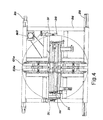
fig. 4 is a top-plan view of the apparatus offig. 1 ; and -
fig. 5 is a perspective view of alternative motorisation means for the rotation about the vertical axis. - As visible in
fig. 1 , a transfer apparatus for a line end of a folder-gluer consists of a transfer bed 1 supported at a certain height by asupport frame 2. - Transfer bed 1 defines a translation plane, wherein a series of flattened boxes is intended to transit. The translation plane is kept at the desired height, i.e. aligned with an entry plane of the flattened boxes, substantially coinciding with an exit plane from a presentation and counting machine. For such purpose,
frame 2 is suitably sized in height, or has adjustment means of the height at which it supports transfer bed 1. - Transfer bed 1 consists of a pair of
transfer assemblies 1a and 1b, a lower one and an upper one, facing each other sandwich-like. The active part of eachtransfer assembly 1a or 1b consists of a pair of drive belts C1 and C2, mounted mutually movable closer together or further apart in a crosswise direction, so as to adapt to the width of the boxes to be processed (for example up to a maximum width of 1200 mm).Fig. 1 shows the extreme position, transversally closer together, of the two pairs of belts, whilefig. 1A shows the same pairs of belts also in the extreme positions, transversally mutually far away. - Between the two pairs of opposite upper belts C1a, C2a and lower belts C1b, C2b a translation track is defined, within which a group or half-bundle of flattened boxes is intended to run, in the number defined by a presentation and counting machine which precedes above.
- The belts are aligned along the transfer direction (i.e. the one shown by the arrow in
fig. 2 ) and allow to drag into the same direction the half-bundle of flattened boxes, from the entry of the device (right hand side offig. 2 ) up to an exit side (left hand side infig. 2 ), wherefrom the boxes are sent to a collection well. - Belts C1 and C2 are guided and driven into movement by a plurality of cylinders 11 mounted at the end of oscillating connecting
rods 12, hinged at the bottom oftransfer assemblies 1a and 1b. Connectingrods 12 are mounted elastically oscillating, in a way known per se, to follow the thickness variation of the box assembly when it runs through the upper and lower belts. - The two
transfer assemblies 1a and 1b are mounted at a fixed mutual distance, but connectingrods 12 are mounted adjustable in their oscillation, so as to arrange respective cylinders 11 at larger or smaller distance from the median translation plane. In other words, the relative distance between the upper belts and the lower belts may be adjusted. Thereby, the sliding track may be widened or reduced in height, housing bundles of boxes of different heights, for example up to 150 mm.Fig. 2 shows the two belts almost touching each other, whilefig. 2A shows the two extreme positions which the arrays of cylinders 11 may take up. - In order to achieve one of the objects of the invention, the transfer apparatus is preferably intended for installation below a presentation and counting machine, wherefrom half-bundles of already stacked boxes come out (for example between 6 and 12 stacked boxes). Transfer bed 1 may hence be built with a reduced length, with respect to what would be required if it was to process the same number of boxes in a fish-scale orientation. In order to achieve such result, the pair of transmission belts must be capable of housing half-bundles having a significant variability of thicknesses between one another, depending on the number and type of box. For such purpose, in the entry and exit area of the
cylinder assembly - Transfer bed 1 is rotatably mounted on
frame 2 along a horizontal axis a-a', transversal to the progress direction of the sliding track. For such purpose, transfer bed 1 is installed on a rigid annular structure 1c, arranged transversally to the sliding track, with which twocoaxial support shafts support shafts posts frame 2. - With one 15 of the two support shafts a pulley is made integral, with which a
transmission belt 23 engages. Said belt comes down as far as the base of therespective post 22, where it engages with a pulley of a first actuation motor M1, hence suited to drive the rotation of transfer bed 1 about flipping over axis a-a'. - The rotation of bed 1 about horizontal axis a-a' may be carried out through angles of ±180°. Due to the limited longitudinal dimensions (i.e. in the direction of progress of the half-bundles), the rotation along the horizontal axis does not generated excessive inertia forces and the height from the ground of axis a-a' remains at acceptable levels which are compatible with the height of the operators.
- According to the invention, moreover, the two
posts horizontal support beam 24, which is rotatably mounted in the plane thereof, i.e. about a vertical axis b-b'. The assembly ofposts beam 24 makes up a U-shaped structure within which transfer bed 1 is oscillatingly mounted. - As clearly visible in
figs. 2 and3 ,beam 24 is installed on a thrust-block bearing 25 integral with abase frame 26. - According to a first embodiment, a drive shaft integral with
beam 24 and running through 25, carries at the lower end thereof adrive pulley 25a, which receives motion from asecond drive belt 25b, driven into motion by a second motor M2 fastened tobase frame 26. Preferably, as visible infigs. 1 and 2 ,pulley 25a andbelt 25b are housed belowbase frame 26. - Motor M2 causes beam 24 - and therefore the whole transfer bed 1 mounted on U-shaped support structure - to perform rotations by a preset angle about vertical axis b-b', in one direction and in the opposite one, depending on plant requirements and layout, for example ±180° or ±90°.
- In order to be able to obtain fast rotations of the apparatus about the vertical axis, despite the inertia of the masses, the motor is preferably assisted by braking means or travel-end means of
beam 24. For example, below beam 24 - at one end thereof - a small, fixedabutment bracket 30 is provided, intended to abut with dissipatingdampeners 31, fastened tounderlying base frame 26, when the two travel-end positions of the rotation are reached, for example at +180° and -180°. The acceleration phase in rotation may hence be managed effectively with the power of motor M2, while in the deceleration phase the electric control on the motor is more effectively assisted by the braking means, thereby overall reducing the rotation times of transfer bed 1. - According to a preferred alternative embodiment, the
beam 24 of the U-shaped frame is constrained to an intermittently rotating plank, actuated by an asynchronous motor driven by a suitable actuation system to obtain the desired speed variations.Fig. 5 shows an exemplifying embodiment of the rotating plank, provided with an actuation motor M2' (for example a three-phase, asynchronous electric motor, piloted through an inverter). - Motor M2' actuates in rotation a horizontal cylinder, provided with a plurality of cam-shaped grooves, with which cylinders integral with the plank engage, arranged circumferentially with axis parallel to the rotation axis of the plank: due to this configuration the mechanical plays are extremely reduced and the rotation inertia is absorbed by the cylinders.
- Thereby, no operation irregularities arise (elastic rebounds) typical of the actuation with toothed belts; moreover, since the plank is lubricated with oil, as well as being suitably sized, the rotation system maintains over time its features of precision and sturdiness and does not require special maintenance.
-
Frame 26 is furthermore provided with displacement members, forexample wheels wheels 27 are suited to slide on arail 29 securely fastened to the floor; the other pair ofwheels 28 is provided with braking means, to prevent free displacement. The displacement allowed to base frame 26 (and consequently of the entire apparatus) fromrail 29 is hence only in one direction, typically the direction transversal to the progress direction of the boxes along the transport line. This contraint allows to perform transversal position adjustments of the apparatus - which are useful when the format of the boxes varies, in order to be able to centre the transfer track with respect to the flattened boxes - but it prevents undesired displacements of the apparatus, caused by the significant inertia forces which are generated with the rotation of transport bed 1 about axis b-b'. In such respect, braking means 31 are preferably oriented so as to release the deceleration forces onframe 26 in a way orthogonal to rail 29: in substance, the braking forces which are released ondampeners 31, during the rotations stop phase, crosswise to the rail and are hence unable to produce any significant apparatus displacement work. - The configuration set forth above hence allows to transfer a group of flattened boxes (half-bundle) from one entry area to an exit area, determining - depending on cases - both the flipping over about horizontal axis a-a', and the rotation on the plane about vertical axis b-b'. The two motors M1 and M2 (or M2') may be controlled independently, so as to possibly mutually combine the two rotations and hence save on transfer times.
- The apparatus according to the invention, inserted between a folder-gluer and a collection well of the bundles of flattened boxes, allows to achieve the necessary transfer flexibility, which makes the entire process fully automatic, up to the binding of the bundles. The main purpose set forth in the premises is hence fully achieved. In case exclusively half-bundles of boxes are processed, with the cylinder displacement device in the transfer bed, it is also possible to limit the bulk of the apparatus and hence dramatically reduce the inertia masses, to the advantage of operation speed and productivity.
- As an example, the whole box processing procedure may be described as in the following, with reference to specific measurements and types which are not to be understood in a limiting sense.
- A series of planar cut dies, of corrugated or solid cardboard, are introduced into a folder-gluer. At the exit of such machine, the flattened boxes undergo a quality check, where they are possibly discarded before being counted and presented to the binding machine.
- Below the quality check a collector is arranged, with a section for counting and presenting the bundle of boxes, for example an EASYPACK™ apparatus, suitable to be installed at the end of the exit section of any type of folder-gluer, for example for twinbox boxes, B-1 boxes, 4-angle and automatic-bottom boxes with overlapping fish-scale orientation.
- The boxes arrive in a fish scale arrangement and are counted through a laser sensor. As an alternative a mechanical counter can be used. The forming of the bundle or half-bundle of flattened boxes occurs through expulsion by pushers, in combination with a system for the support of the scales arrangement, without ever arresting the progress of the boxes coming from the exit section of the folder-gluer. The collector operates with any kind of box: in the case of boxes with an irregular rear side (as automatic bottom with cover), the pushers may be offset, for example up to 500 mm.
- In order to maintain bundle stability during expulsion, an adjustable upper lamina may be provided, in addition to two front stops, which ensure the perfect squaring of the bundle and which act automatically depending on box height.
- Exemplifying sizes of boxes which may be processed are minimum 200 x 150 mm and maximum 1500 x 1200 mm. The bundles are formed at a certain rate, for example maximum one bundle every 3 seconds. Therefore, for example, with a 5-box bundle 6,000 boxes are processed in an hour, with a 10-box bundle a rate of 12,000 boxes/hour is obtained, and so on.
- At the exit of the collector the transfer apparatus according to the invention is arranged, which then precedes the transfer into the collection well. The partial bundles, counted and pushed by the collector, are gripped in the entry section by the belt sandwich and transferred entirely into transfer bed 1. Here the partial bundle is arrested and then it possibly undergoes one or more rotations according to the flipping over axis and the rotation axis on the plane. Thereby 4 possible operations are determined:
- gripping of the half-bundle and leading into the well as the half-bundle has been received;
- gripping of the half-bundle, flipping over by 180° on the horizontal axis in the movement direction and deposit in the well;
- gripping of the half-bundle, rotation with respect to the vertical axis and deposit in the well;
- gripping of the half-bundle, rotation by 180° on the vertical axis and at the same time in a horizontal axis and deposit in the well.
- The belt sandwich may house a half-bundle as tall as 150 mm.
- The motorised belts may first move automatically, to position themselves laterally depending on the box width.
- Work cycles are with the same cyclicity as the preceding collector, for example an action every 3 seconds, while the work sequence (of the four ones indicated above) is chosen according to the type of box.
- The well receives the partial bundles and then, through the lateral pusher and upper pressing element, it leads the completed bundle as far as a binding machine, for example a bow strapping apparatus, provided with front stop.
- The binding machine, working in line or at 90°, can bind either transversally or in the direction of movement, performing one or more bindings. Similarly, depending on specific requirements or specific box designs, the rotation on vertical axis b-b' may occur even at 90°.
- After which the bundle is expelled onto a belt arranged longitudinally to the direction of movement, to deposit it onto an idle roller unit which acts as an accumulation lung for palletisation.
- However, it is understood that the invention is not limited to the specific configurations illustrated above, which represent only non-limiting examples of the scope of the invention, but that a number of variants are possible, all within the reach of a person skilled in the field, without departing from the scope of the invention.
- In particular, posts 21 and 22 and
beam 24, which form a generically U-shaped support structure, may take up also other specific shapes. For example,beam 24 may also be in the shape of a circular platform. - Again, although it has not been specifically described, the braking system to the vertical rotation of transfer bed 1, employed between
beam 24 andframe 26, may be employed in a similar way also on the upside down rotation about the horizontal axis, as synthetically shown infigs. 1 and 2 bydampener devices 32. - Again, the braking means are substantially essential in the presence of a transmission with strong plays (such as a toothed belt transmission), while it could also be done without in case the rotating plank with integrated motor M2' is employed.
Claims (15)
- Transfer apparatus for a line end of a folder-gluer for cardboard boxes, of the type comprising a transfer bed (1) with a double, opposite array of transmission belts (C1a, C1b, C2a, C2b) which define a transfer track for the displacement of flattened folded boxes, characterised in that said transfer bed (1) is oscillatingly mounted about a horizontal axis (a-a') on a U-shaped support structure (21, 22, 24) which is in turn rotatingly mounted according to a vertical axis (b-b') on a base frame (26), the rotation according to the horizontal axis (a-a') and according to the vertical axis (b-b') occurring through a first (M1) and a second (M2, M2') motor, respectively.
- Apparatus as claimed in claim 1, wherein said U-shaped support structure (21, 22, 24) is rotatingly mounted through a fifth-wheel bearing (25) and is integral in rotation with drive means motorised by said second motor (M2, M2').
- Apparatus as claimed in claim 2, wherein said drive means consist of a drive shaft which runs through said base frame (26) ending below with a driving pulley (25a).
- Apparatus as claimed in claim 3, wherein said driving pulley (25a) is engaged with a transmission belt (25b) housed below the base frame (26) and connected with said respective second motor (M2) mounted on said base frame (26).
- Apparatus as claimed in any one of the preceding claims, wherein braking means (30, 31) are provided at least between said U-shaped structure (21, 22, 24) and said base frame (26) for decelerating the rotation of the U-shaped structure about the vertical rotation axis (b-b').
- Apparatus as claimed in claim 5, wherein said braking means are shaped as a dissipating dampener (31).
- Apparatus as claimed in any one of the preceding claims, wherein said base frame (26) rests on the floor through displacement means (27, 28, 29).
- Apparatus as claimed in claim 7, wherein said displacement members comprise at least one pair of wheels (27) translatable on a rail (29) which may be fastened to the floor.
- Apparatus as claimed in claim 8, wherein said rail (29) is arranged orthogonally to a direction of movement of said transfer track.
- Apparatus as claimed in claim 8 or 9, wherein said rail (29) is orthogonal to a main direction along which a deceleration load of the rotation of said transfer bed (1) acts.
- Apparatus as claimed in any one of the preceding claims, wherein said U-shaped support structure comprises two lateral posts (21, 22) at the upper ends whereof rotation bearings are provided with which support shafts engage (15, 16) of said transfer bed (1) which define said horizontal rotation axis (a-a').
- Apparatus as claimed in claim 11, wherein one of said support shafts (15) is integral with a pulley engaged with a transmission belt (23) connected to said respective first motor (M1) integral with the U-shaped structure (22).
- Apparatus as claimed in any one of the preceding claims, wherein said double array of opposite belts (C1a, C1b, C2a, C2b) is adjustable in position both in a crosswise direction to the transfer track, and in the direction of the relative distance thereof.
- Apparatus as claimed in claim 13, wherein said belts (C1, C2) are guided by a plurality of cylinders which may be adapted in position.
- Apparatus as claimed in claim 13, wherein there are provided at least input cylinders (111) and output cylinders (112) driven in position to cyclically determine the opening in height of an input section and of an output section of said double array of opposite belts (C1, C2).
Priority Applications (1)
| Application Number | Priority Date | Filing Date | Title |
|---|---|---|---|
| PL11168176T PL2392451T3 (en) | 2010-06-04 | 2011-05-31 | Transfer apparatus for a line end of a folder-gluer |
Applications Claiming Priority (1)
| Application Number | Priority Date | Filing Date | Title |
|---|---|---|---|
| ITMI20100189 ITMI20100189U1 (en) | 2010-06-04 | 2010-06-04 | TRANSFER EQUIPMENT FOR A LINE END OF A FOLDING MACHINE. |
Publications (3)
| Publication Number | Publication Date |
|---|---|
| EP2392451A2 true EP2392451A2 (en) | 2011-12-07 |
| EP2392451A3 EP2392451A3 (en) | 2015-09-30 |
| EP2392451B1 EP2392451B1 (en) | 2019-07-03 |
Family
ID=43740514
Family Applications (1)
| Application Number | Title | Priority Date | Filing Date |
|---|---|---|---|
| EP11168176.3A Active EP2392451B1 (en) | 2010-06-04 | 2011-05-31 | Transfer apparatus for a line end of a folder-gluer |
Country Status (5)
| Country | Link |
|---|---|
| US (1) | US8684657B2 (en) |
| EP (1) | EP2392451B1 (en) |
| ES (1) | ES2747999T3 (en) |
| IT (1) | ITMI20100189U1 (en) |
| PL (1) | PL2392451T3 (en) |
Cited By (9)
| Publication number | Priority date | Publication date | Assignee | Title |
|---|---|---|---|---|
| CN105891439A (en) * | 2016-05-27 | 2016-08-24 | 燕山大学 | Six-surface flaw detection device for composite board and method |
| WO2018007016A1 (en) * | 2016-07-05 | 2018-01-11 | Bobst Mex Sa | Double-endless-belt conveyor, turnover module incorporating such a conveyor and folding package production line incorporating such a module |
| WO2018007017A1 (en) * | 2016-07-05 | 2018-01-11 | Bobst Mex Sa | Module for turning over folding packages and folding package production line incorporating such a module |
| CN110406979A (en) * | 2019-07-05 | 2019-11-05 | 上海提牛机电设备有限公司 | A kind of ceramic disk turnover mechanism and ceramic disk feed system |
| CN111519873A (en) * | 2020-05-09 | 2020-08-11 | 广东博智林机器人有限公司 | Plate turnover and ceramic tile paving equipment |
| CN112123743A (en) * | 2020-09-04 | 2020-12-25 | 许昌学院 | A leveling device for transparent substrate of Fabry-Perot interferometer |
| CN112320293A (en) * | 2020-11-11 | 2021-02-05 | 中山市拓电电子科技有限公司 | Tobacco leaf box body overturning control method |
| CN115709890A (en) * | 2022-11-22 | 2023-02-24 | 中国船舶集团有限公司第七〇四研究所 | Automatic overturning and righting mechanism for goods |
| CN119018703A (en) * | 2024-10-30 | 2024-11-26 | 国网安徽省电力有限公司当涂县供电公司 | A cable conveyor |
Families Citing this family (10)
| Publication number | Priority date | Publication date | Assignee | Title |
|---|---|---|---|---|
| WO2013113488A1 (en) * | 2012-02-03 | 2013-08-08 | Bobst Mex Sa | Method for collecting samples of flat objects in a packaging machine and packaging machine for implementing said method |
| DE102013101149A1 (en) * | 2013-02-05 | 2014-08-21 | Windmöller & Hölscher Kg | Device for turning and transporting an object |
| CN105253660B (en) * | 2015-10-12 | 2017-11-24 | 燕山大学 | A kind of turnable roll-type composite sheet conveying device with rotating base |
| WO2017222092A1 (en) * | 2016-06-23 | 2017-12-28 | 에이스기계(주) | Nick breaking device |
| CN109368218A (en) * | 2018-09-14 | 2019-02-22 | 安徽建联木业有限公司 | A kind of plank clamping turnover mechanism |
| CN112425966B (en) * | 2020-11-13 | 2021-12-07 | 深圳市新厨厨房设备有限公司 | Intelligent refrigerated food arc-shaped bi-pass display cabinet |
| CN114229426A (en) * | 2021-11-30 | 2022-03-25 | 浙江赛摩智能科技有限公司 | Online intermittent type 180-degree high-speed turnover device suitable for flat products |
| US12024367B1 (en) * | 2022-02-04 | 2024-07-02 | Amazon Technologies, Inc. | Automated container provisioning systems and methods |
| CN115520635A (en) * | 2022-07-07 | 2022-12-27 | 苏州爱德天汇自动化设备有限公司 | Full-automatic product upset machine |
| CN119503416A (en) * | 2025-01-21 | 2025-02-25 | 大连美德乐工业自动化股份有限公司 | A conveyor with conveying surface width adjustment and flipping functions |
Family Cites Families (25)
| Publication number | Priority date | Publication date | Assignee | Title |
|---|---|---|---|---|
| US763307A (en) * | 1903-07-08 | 1904-06-21 | Frederick Mills | Apparatus for moving rails, &c., in relation to the rolls of rolling-mills. |
| US2865516A (en) * | 1953-11-10 | 1958-12-23 | Greenlee Bros & Co | Turnover apparatus |
| US3089598A (en) * | 1960-07-06 | 1963-05-14 | Virginia N Temple | Apparatus for inverting loads |
| FR1567938A (en) * | 1967-11-15 | 1969-05-23 | ||
| JPS54116369U (en) * | 1978-02-02 | 1979-08-15 | ||
| JPS5719217A (en) * | 1980-07-04 | 1982-02-01 | Mitsubishi Motors Corp | Transport material inverting device |
| US4606452A (en) * | 1985-01-24 | 1986-08-19 | Lecrone Dale S | Conveyor and work station for turning bakery products |
| US4699564A (en) * | 1986-06-20 | 1987-10-13 | Cetrangolo D L | Stone turning apparatus with swing transfer |
| US4798278A (en) * | 1987-07-23 | 1989-01-17 | General Machine Design, Inc. | Conveyor for turning packages upside down |
| DE4127207A1 (en) * | 1991-08-19 | 1993-02-25 | Kolbus Gmbh & Co Kg | DEVICE FOR TRANSFERING BOOKS OR THE LIKE PRODUCTS FROM A STANDING POSITION TO A LYING POSITION |
| US5450940A (en) * | 1994-05-03 | 1995-09-19 | Kolbus Gmbh & Co. Kg | Delivery system for book-sewing machine |
| US5979634A (en) * | 1997-10-17 | 1999-11-09 | Paper Converting Machine Company | Infeed section for packaging apparatus |
| ITMI991140A1 (en) * | 1999-05-24 | 2000-11-24 | O M G Di G Pessina E A Perobel | CONVEYOR AND ROTATION APPARATUS OF PACKAGES OF BOOKS OR SIMILAR |
| IT1316314B1 (en) * | 2000-01-31 | 2003-04-10 | Sitma Spa | TURNING DEVICE FOR EDITORIAL GRAPHIC PRODUCTS IN A TRANSPORT AND / OR PACKAGING LINE |
| US6851920B2 (en) * | 2000-10-25 | 2005-02-08 | Adolf Illig Maschinenbau Gmbh & Co. | Method for stacking parts comprising thermoplastic plastic, and apparatus for executing the method |
| WO2003011723A1 (en) * | 2001-07-11 | 2003-02-13 | Pulsar S.R.L. | Method and device for aligning articles and means for detecting the position of the articles |
| DE10210843A1 (en) * | 2002-03-12 | 2003-10-09 | Horst Rathert | Perfect binders for the production of blocks and brochures, especially for short runs |
| CH695266A5 (en) * | 2002-04-03 | 2006-02-28 | Bobst Sa | Device for return of material cell sheet. |
| JP2004025448A (en) * | 2002-06-21 | 2004-01-29 | Heian Corp | Jigless machining apparatus |
| DE10236069B4 (en) * | 2002-08-07 | 2004-07-08 | Uhlmann Pac-Systeme Gmbh & Co Kg | Device for removing flat folded folding boxes from a magazine shaft and transferring them to a conveyor |
| SE0301457L (en) * | 2003-05-20 | 2004-11-21 | Cargine Engineering Ab | Method and device for pneumatic operation of a tool |
| DE10344383A1 (en) * | 2003-09-23 | 2005-04-28 | Buerkle Gmbh Robert | Method and device for coating components |
| US7175017B2 (en) * | 2004-06-22 | 2007-02-13 | Lockheed Martin Corporation | In-line flipper mechanism and conveyor system for achieving the proper orientation of mail tray and mail tub receptacles |
| EP1645434B1 (en) * | 2004-10-07 | 2008-07-02 | Müller Martini Holding AG | Apparatus for the sychronised processing of a book block made of at least one printed sheet |
| US8181767B2 (en) * | 2009-02-27 | 2012-05-22 | Weldon Machine Tool, Inc. | Product inverting mechanism |
-
2010
- 2010-06-04 IT ITMI20100189 patent/ITMI20100189U1/en unknown
-
2011
- 2011-05-31 ES ES11168176T patent/ES2747999T3/en active Active
- 2011-05-31 PL PL11168176T patent/PL2392451T3/en unknown
- 2011-05-31 EP EP11168176.3A patent/EP2392451B1/en active Active
- 2011-06-06 US US13/154,052 patent/US8684657B2/en not_active Expired - Fee Related
Non-Patent Citations (1)
| Title |
|---|
| None |
Cited By (15)
| Publication number | Priority date | Publication date | Assignee | Title |
|---|---|---|---|---|
| CN105891439A (en) * | 2016-05-27 | 2016-08-24 | 燕山大学 | Six-surface flaw detection device for composite board and method |
| EP4063304A1 (en) * | 2016-07-05 | 2022-09-28 | Bobst Mex Sa | Module for turning over folding packages and folding package production line incorporating such a module |
| WO2018007016A1 (en) * | 2016-07-05 | 2018-01-11 | Bobst Mex Sa | Double-endless-belt conveyor, turnover module incorporating such a conveyor and folding package production line incorporating such a module |
| WO2018007017A1 (en) * | 2016-07-05 | 2018-01-11 | Bobst Mex Sa | Module for turning over folding packages and folding package production line incorporating such a module |
| CN109689546A (en) * | 2016-07-05 | 2019-04-26 | 鲍勃斯脱梅克斯股份有限公司 | A double endless conveyor belt conveyor, a turning module combined with the conveyor, and a folding packaging production line combined with the module |
| US10618758B2 (en) | 2016-07-05 | 2020-04-14 | Bobst Mex Sa | Double-endless-belt conveyor, turnover module incorporating such a conveyor and folding package production line incorporating such a module |
| US10829327B2 (en) | 2016-07-05 | 2020-11-10 | Bobst Mex Sa | Module for turning over folding packages and folding package production line incorporating such a module |
| CN109689546B (en) * | 2016-07-05 | 2020-11-17 | 鲍勃斯脱梅克斯股份有限公司 | Double-annular conveying belt conveyor, overturning module combined with same and folding packaging production line combined with same |
| CN110406979A (en) * | 2019-07-05 | 2019-11-05 | 上海提牛机电设备有限公司 | A kind of ceramic disk turnover mechanism and ceramic disk feed system |
| CN111519873A (en) * | 2020-05-09 | 2020-08-11 | 广东博智林机器人有限公司 | Plate turnover and ceramic tile paving equipment |
| CN112123743B (en) * | 2020-09-04 | 2022-02-01 | 许昌学院 | Leveling device for Fabry-Perot interferometer transparent substrate |
| CN112123743A (en) * | 2020-09-04 | 2020-12-25 | 许昌学院 | A leveling device for transparent substrate of Fabry-Perot interferometer |
| CN112320293A (en) * | 2020-11-11 | 2021-02-05 | 中山市拓电电子科技有限公司 | Tobacco leaf box body overturning control method |
| CN115709890A (en) * | 2022-11-22 | 2023-02-24 | 中国船舶集团有限公司第七〇四研究所 | Automatic overturning and righting mechanism for goods |
| CN119018703A (en) * | 2024-10-30 | 2024-11-26 | 国网安徽省电力有限公司当涂县供电公司 | A cable conveyor |
Also Published As
| Publication number | Publication date |
|---|---|
| ITMI20100189U1 (en) | 2011-12-05 |
| US8684657B2 (en) | 2014-04-01 |
| PL2392451T3 (en) | 2019-12-31 |
| EP2392451A3 (en) | 2015-09-30 |
| EP2392451B1 (en) | 2019-07-03 |
| US20110297507A1 (en) | 2011-12-08 |
| ES2747999T3 (en) | 2020-03-12 |
Similar Documents
| Publication | Publication Date | Title |
|---|---|---|
| EP2392451B1 (en) | Transfer apparatus for a line end of a folder-gluer | |
| US6145281A (en) | Method and apparatus for packaging a series of articles in different formations | |
| US6793064B2 (en) | Retractable transfer device metering and product arranging and loading apparatus and methods | |
| EP1490280B1 (en) | Retractable transfer device for a metering apparatus | |
| JPH0656105A (en) | Device for manufacturing carton | |
| JP2935526B2 (en) | Separation equipment for unbound stacking | |
| JPS606861B2 (en) | Flat work piece stacking device | |
| US6238173B1 (en) | Apparatus for placing groups of products on pallets | |
| US3631651A (en) | Device for groupwise packing of bags | |
| US12522465B2 (en) | System and a method for stacking a fanfolded continuous web of sheet material | |
| JP2002079493A (en) | Cutting device for automatically cutting printed matter | |
| CN112918790A (en) | Automatic boxing equipment | |
| CN216189824U (en) | Paper collecting mechanism and paper collecting equipment | |
| EP4284720B1 (en) | Apparatus for strapping packaging or packaging materials, and methods of use | |
| EP3064343B1 (en) | A folding apparatus for folding sheet packaging elements | |
| CN206494174U (en) | A kind of multifunctional high speed packing machine differential feed arrangement | |
| CN206494188U (en) | A kind of multifunctional high speed packing machine Cheng Ye mechanisms | |
| US8529186B2 (en) | Collecting and transport device for a stack formed by layers of sheets | |
| CN110589081A (en) | Cartoning machine feed arrangement and dress box system | |
| CN117262325B (en) | A box-making machine | |
| CN115557005B (en) | A cardboard box stacking device | |
| US5261782A (en) | Continuous stacking apparatus | |
| WO2026078543A1 (en) | Method and system for bundling stacked containers | |
| JP2023069409A (en) | Automatic sorting, counting and sorting equipment | |
| JP3333437B2 (en) | Stacking equipment for sheet material |
Legal Events
| Date | Code | Title | Description |
|---|---|---|---|
| AK | Designated contracting states |
Kind code of ref document: A2 Designated state(s): AL AT BE BG CH CY CZ DE DK EE ES FI FR GB GR HR HU IE IS IT LI LT LU LV MC MK MT NL NO PL PT RO RS SE SI SK SM TR |
|
| AX | Request for extension of the european patent |
Extension state: BA ME |
|
| PUAI | Public reference made under article 153(3) epc to a published international application that has entered the european phase |
Free format text: ORIGINAL CODE: 0009012 |
|
| RIC1 | Information provided on ipc code assigned before grant |
Ipc: B65G 47/244 20060101ALI20150427BHEP Ipc: B65G 15/14 20060101ALI20150427BHEP Ipc: B31B 1/92 20060101AFI20150427BHEP Ipc: B31B 1/98 20060101ALI20150427BHEP Ipc: B65G 47/252 20060101ALI20150427BHEP |
|
| PUAL | Search report despatched |
Free format text: ORIGINAL CODE: 0009013 |
|
| AK | Designated contracting states |
Kind code of ref document: A3 Designated state(s): AL AT BE BG CH CY CZ DE DK EE ES FI FR GB GR HR HU IE IS IT LI LT LU LV MC MK MT NL NO PL PT RO RS SE SI SK SM TR |
|
| AX | Request for extension of the european patent |
Extension state: BA ME |
|
| RIC1 | Information provided on ipc code assigned before grant |
Ipc: B31B 1/92 20060101AFI20150821BHEP Ipc: B65G 15/14 20060101ALI20150821BHEP Ipc: B31B 1/98 20060101ALI20150821BHEP Ipc: B65G 47/244 20060101ALI20150821BHEP Ipc: B65G 47/252 20060101ALI20150821BHEP |
|
| 17P | Request for examination filed |
Effective date: 20160330 |
|
| RBV | Designated contracting states (corrected) |
Designated state(s): AL AT BE BG CH CY CZ DE DK EE ES FI FR GB GR HR HU IE IS IT LI LT LU LV MC MK MT NL NO PL PT RO RS SE SI SK SM TR |
|
| STAA | Information on the status of an ep patent application or granted ep patent |
Free format text: STATUS: EXAMINATION IS IN PROGRESS |
|
| 17Q | First examination report despatched |
Effective date: 20170503 |
|
| RAP1 | Party data changed (applicant data changed or rights of an application transferred) |
Owner name: VEGA S.R.L. |
|
| REG | Reference to a national code |
Ref country code: DE Ref legal event code: R079 Ref document number: 602011060155 Country of ref document: DE Free format text: PREVIOUS MAIN CLASS: B31B0001920000 Ipc: B31B0050920000 |
|
| RIC1 | Information provided on ipc code assigned before grant |
Ipc: B65G 47/252 20060101ALI20190123BHEP Ipc: B65G 15/14 20060101ALI20190123BHEP Ipc: B65G 47/244 20060101ALI20190123BHEP Ipc: B65H 5/02 20060101ALI20190123BHEP Ipc: B65H 31/30 20060101ALN20190123BHEP Ipc: B31B 50/98 20170101ALI20190123BHEP Ipc: B31B 50/92 20170101AFI20190123BHEP Ipc: B65H 29/12 20060101ALN20190123BHEP Ipc: B65H 15/00 20060101ALI20190123BHEP Ipc: B65H 11/00 20060101ALI20190123BHEP |
|
| GRAP | Despatch of communication of intention to grant a patent |
Free format text: ORIGINAL CODE: EPIDOSNIGR1 |
|
| STAA | Information on the status of an ep patent application or granted ep patent |
Free format text: STATUS: GRANT OF PATENT IS INTENDED |
|
| RIC1 | Information provided on ipc code assigned before grant |
Ipc: B65H 29/12 20060101ALN20190212BHEP Ipc: B31B 50/92 20170101AFI20190212BHEP Ipc: B65G 47/252 20060101ALI20190212BHEP Ipc: B65G 15/14 20060101ALI20190212BHEP Ipc: B31B 50/98 20170101ALI20190212BHEP Ipc: B65G 47/244 20060101ALI20190212BHEP Ipc: B65H 5/02 20060101ALI20190212BHEP Ipc: B65H 31/30 20060101ALN20190212BHEP Ipc: B65H 15/00 20060101ALI20190212BHEP Ipc: B65H 11/00 20060101ALI20190212BHEP |
|
| INTG | Intention to grant announced |
Effective date: 20190301 |
|
| GRAS | Grant fee paid |
Free format text: ORIGINAL CODE: EPIDOSNIGR3 |
|
| GRAA | (expected) grant |
Free format text: ORIGINAL CODE: 0009210 |
|
| STAA | Information on the status of an ep patent application or granted ep patent |
Free format text: STATUS: THE PATENT HAS BEEN GRANTED |
|
| AK | Designated contracting states |
Kind code of ref document: B1 Designated state(s): AL AT BE BG CH CY CZ DE DK EE ES FI FR GB GR HR HU IE IS IT LI LT LU LV MC MK MT NL NO PL PT RO RS SE SI SK SM TR |
|
| REG | Reference to a national code |
Ref country code: GB Ref legal event code: FG4D |
|
| REG | Reference to a national code |
Ref country code: CH Ref legal event code: EP Ref country code: AT Ref legal event code: REF Ref document number: 1150464 Country of ref document: AT Kind code of ref document: T Effective date: 20190715 |
|
| REG | Reference to a national code |
Ref country code: DE Ref legal event code: R096 Ref document number: 602011060155 Country of ref document: DE |
|
| REG | Reference to a national code |
Ref country code: IE Ref legal event code: FG4D |
|
| REG | Reference to a national code |
Ref country code: NL Ref legal event code: MP Effective date: 20190703 |
|
| REG | Reference to a national code |
Ref country code: LT Ref legal event code: MG4D |
|
| REG | Reference to a national code |
Ref country code: AT Ref legal event code: MK05 Ref document number: 1150464 Country of ref document: AT Kind code of ref document: T Effective date: 20190703 |
|
| PG25 | Lapsed in a contracting state [announced via postgrant information from national office to epo] |
Ref country code: FI Free format text: LAPSE BECAUSE OF FAILURE TO SUBMIT A TRANSLATION OF THE DESCRIPTION OR TO PAY THE FEE WITHIN THE PRESCRIBED TIME-LIMIT Effective date: 20190703 Ref country code: CZ Free format text: LAPSE BECAUSE OF FAILURE TO SUBMIT A TRANSLATION OF THE DESCRIPTION OR TO PAY THE FEE WITHIN THE PRESCRIBED TIME-LIMIT Effective date: 20190703 Ref country code: AT Free format text: LAPSE BECAUSE OF FAILURE TO SUBMIT A TRANSLATION OF THE DESCRIPTION OR TO PAY THE FEE WITHIN THE PRESCRIBED TIME-LIMIT Effective date: 20190703 Ref country code: NO Free format text: LAPSE BECAUSE OF FAILURE TO SUBMIT A TRANSLATION OF THE DESCRIPTION OR TO PAY THE FEE WITHIN THE PRESCRIBED TIME-LIMIT Effective date: 20191003 Ref country code: SE Free format text: LAPSE BECAUSE OF FAILURE TO SUBMIT A TRANSLATION OF THE DESCRIPTION OR TO PAY THE FEE WITHIN THE PRESCRIBED TIME-LIMIT Effective date: 20190703 Ref country code: BG Free format text: LAPSE BECAUSE OF FAILURE TO SUBMIT A TRANSLATION OF THE DESCRIPTION OR TO PAY THE FEE WITHIN THE PRESCRIBED TIME-LIMIT Effective date: 20191003 Ref country code: PT Free format text: LAPSE BECAUSE OF FAILURE TO SUBMIT A TRANSLATION OF THE DESCRIPTION OR TO PAY THE FEE WITHIN THE PRESCRIBED TIME-LIMIT Effective date: 20191104 Ref country code: NL Free format text: LAPSE BECAUSE OF FAILURE TO SUBMIT A TRANSLATION OF THE DESCRIPTION OR TO PAY THE FEE WITHIN THE PRESCRIBED TIME-LIMIT Effective date: 20190703 Ref country code: LT Free format text: LAPSE BECAUSE OF FAILURE TO SUBMIT A TRANSLATION OF THE DESCRIPTION OR TO PAY THE FEE WITHIN THE PRESCRIBED TIME-LIMIT Effective date: 20190703 Ref country code: HR Free format text: LAPSE BECAUSE OF FAILURE TO SUBMIT A TRANSLATION OF THE DESCRIPTION OR TO PAY THE FEE WITHIN THE PRESCRIBED TIME-LIMIT Effective date: 20190703 |
|
| PG25 | Lapsed in a contracting state [announced via postgrant information from national office to epo] |
Ref country code: IS Free format text: LAPSE BECAUSE OF FAILURE TO SUBMIT A TRANSLATION OF THE DESCRIPTION OR TO PAY THE FEE WITHIN THE PRESCRIBED TIME-LIMIT Effective date: 20191103 Ref country code: RS Free format text: LAPSE BECAUSE OF FAILURE TO SUBMIT A TRANSLATION OF THE DESCRIPTION OR TO PAY THE FEE WITHIN THE PRESCRIBED TIME-LIMIT Effective date: 20190703 Ref country code: GR Free format text: LAPSE BECAUSE OF FAILURE TO SUBMIT A TRANSLATION OF THE DESCRIPTION OR TO PAY THE FEE WITHIN THE PRESCRIBED TIME-LIMIT Effective date: 20191004 Ref country code: AL Free format text: LAPSE BECAUSE OF FAILURE TO SUBMIT A TRANSLATION OF THE DESCRIPTION OR TO PAY THE FEE WITHIN THE PRESCRIBED TIME-LIMIT Effective date: 20190703 Ref country code: LV Free format text: LAPSE BECAUSE OF FAILURE TO SUBMIT A TRANSLATION OF THE DESCRIPTION OR TO PAY THE FEE WITHIN THE PRESCRIBED TIME-LIMIT Effective date: 20190703 |
|
| REG | Reference to a national code |
Ref country code: ES Ref legal event code: FG2A Ref document number: 2747999 Country of ref document: ES Kind code of ref document: T3 Effective date: 20200312 |
|
| PG25 | Lapsed in a contracting state [announced via postgrant information from national office to epo] |
Ref country code: TR Free format text: LAPSE BECAUSE OF FAILURE TO SUBMIT A TRANSLATION OF THE DESCRIPTION OR TO PAY THE FEE WITHIN THE PRESCRIBED TIME-LIMIT Effective date: 20190703 |
|
| PG25 | Lapsed in a contracting state [announced via postgrant information from national office to epo] |
Ref country code: EE Free format text: LAPSE BECAUSE OF FAILURE TO SUBMIT A TRANSLATION OF THE DESCRIPTION OR TO PAY THE FEE WITHIN THE PRESCRIBED TIME-LIMIT Effective date: 20190703 Ref country code: DK Free format text: LAPSE BECAUSE OF FAILURE TO SUBMIT A TRANSLATION OF THE DESCRIPTION OR TO PAY THE FEE WITHIN THE PRESCRIBED TIME-LIMIT Effective date: 20190703 Ref country code: RO Free format text: LAPSE BECAUSE OF FAILURE TO SUBMIT A TRANSLATION OF THE DESCRIPTION OR TO PAY THE FEE WITHIN THE PRESCRIBED TIME-LIMIT Effective date: 20190703 |
|
| PG25 | Lapsed in a contracting state [announced via postgrant information from national office to epo] |
Ref country code: SK Free format text: LAPSE BECAUSE OF FAILURE TO SUBMIT A TRANSLATION OF THE DESCRIPTION OR TO PAY THE FEE WITHIN THE PRESCRIBED TIME-LIMIT Effective date: 20190703 Ref country code: SM Free format text: LAPSE BECAUSE OF FAILURE TO SUBMIT A TRANSLATION OF THE DESCRIPTION OR TO PAY THE FEE WITHIN THE PRESCRIBED TIME-LIMIT Effective date: 20190703 Ref country code: IS Free format text: LAPSE BECAUSE OF FAILURE TO SUBMIT A TRANSLATION OF THE DESCRIPTION OR TO PAY THE FEE WITHIN THE PRESCRIBED TIME-LIMIT Effective date: 20200224 |
|
| REG | Reference to a national code |
Ref country code: DE Ref legal event code: R097 Ref document number: 602011060155 Country of ref document: DE |
|
| PLBE | No opposition filed within time limit |
Free format text: ORIGINAL CODE: 0009261 |
|
| STAA | Information on the status of an ep patent application or granted ep patent |
Free format text: STATUS: NO OPPOSITION FILED WITHIN TIME LIMIT |
|
| PG2D | Information on lapse in contracting state deleted |
Ref country code: IS |
|
| 26N | No opposition filed |
Effective date: 20200603 |
|
| PG25 | Lapsed in a contracting state [announced via postgrant information from national office to epo] |
Ref country code: SI Free format text: LAPSE BECAUSE OF FAILURE TO SUBMIT A TRANSLATION OF THE DESCRIPTION OR TO PAY THE FEE WITHIN THE PRESCRIBED TIME-LIMIT Effective date: 20190703 |
|
| REG | Reference to a national code |
Ref country code: DE Ref legal event code: R119 Ref document number: 602011060155 Country of ref document: DE |
|
| PG25 | Lapsed in a contracting state [announced via postgrant information from national office to epo] |
Ref country code: MC Free format text: LAPSE BECAUSE OF FAILURE TO SUBMIT A TRANSLATION OF THE DESCRIPTION OR TO PAY THE FEE WITHIN THE PRESCRIBED TIME-LIMIT Effective date: 20190703 Ref country code: LI Free format text: LAPSE BECAUSE OF NON-PAYMENT OF DUE FEES Effective date: 20200531 Ref country code: CH Free format text: LAPSE BECAUSE OF NON-PAYMENT OF DUE FEES Effective date: 20200531 |
|
| REG | Reference to a national code |
Ref country code: BE Ref legal event code: MM Effective date: 20200531 |
|
| PG25 | Lapsed in a contracting state [announced via postgrant information from national office to epo] |
Ref country code: LU Free format text: LAPSE BECAUSE OF NON-PAYMENT OF DUE FEES Effective date: 20200531 |
|
| PG25 | Lapsed in a contracting state [announced via postgrant information from national office to epo] |
Ref country code: IE Free format text: LAPSE BECAUSE OF NON-PAYMENT OF DUE FEES Effective date: 20200531 Ref country code: FR Free format text: LAPSE BECAUSE OF NON-PAYMENT OF DUE FEES Effective date: 20200531 |
|
| PG25 | Lapsed in a contracting state [announced via postgrant information from national office to epo] |
Ref country code: BE Free format text: LAPSE BECAUSE OF NON-PAYMENT OF DUE FEES Effective date: 20200531 Ref country code: DE Free format text: LAPSE BECAUSE OF NON-PAYMENT OF DUE FEES Effective date: 20201201 |
|
| PG25 | Lapsed in a contracting state [announced via postgrant information from national office to epo] |
Ref country code: MT Free format text: LAPSE BECAUSE OF FAILURE TO SUBMIT A TRANSLATION OF THE DESCRIPTION OR TO PAY THE FEE WITHIN THE PRESCRIBED TIME-LIMIT Effective date: 20190703 Ref country code: CY Free format text: LAPSE BECAUSE OF FAILURE TO SUBMIT A TRANSLATION OF THE DESCRIPTION OR TO PAY THE FEE WITHIN THE PRESCRIBED TIME-LIMIT Effective date: 20190703 |
|
| PG25 | Lapsed in a contracting state [announced via postgrant information from national office to epo] |
Ref country code: MK Free format text: LAPSE BECAUSE OF FAILURE TO SUBMIT A TRANSLATION OF THE DESCRIPTION OR TO PAY THE FEE WITHIN THE PRESCRIBED TIME-LIMIT Effective date: 20190703 |
|
| P01 | Opt-out of the competence of the unified patent court (upc) registered |
Effective date: 20230516 |
|
| PGFP | Annual fee paid to national office [announced via postgrant information from national office to epo] |
Ref country code: PL Payment date: 20250526 Year of fee payment: 15 |
|
| PGFP | Annual fee paid to national office [announced via postgrant information from national office to epo] |
Ref country code: GB Payment date: 20250526 Year of fee payment: 15 Ref country code: ES Payment date: 20250602 Year of fee payment: 15 |
|
| PGFP | Annual fee paid to national office [announced via postgrant information from national office to epo] |
Ref country code: IT Payment date: 20250523 Year of fee payment: 15 |