EP2392373A1 - Nasensprayvorrichtung - Google Patents
Nasensprayvorrichtung Download PDFInfo
- Publication number
- EP2392373A1 EP2392373A1 EP11250576A EP11250576A EP2392373A1 EP 2392373 A1 EP2392373 A1 EP 2392373A1 EP 11250576 A EP11250576 A EP 11250576A EP 11250576 A EP11250576 A EP 11250576A EP 2392373 A1 EP2392373 A1 EP 2392373A1
- Authority
- EP
- European Patent Office
- Prior art keywords
- rod
- tube
- mount
- reception
- push member
- Prior art date
- Legal status (The legal status is an assumption and is not a legal conclusion. Google has not performed a legal analysis and makes no representation as to the accuracy of the status listed.)
- Withdrawn
Links
Images


Classifications
-
- A—HUMAN NECESSITIES
- A61—MEDICAL OR VETERINARY SCIENCE; HYGIENE
- A61M—DEVICES FOR INTRODUCING MEDIA INTO, OR ONTO, THE BODY; DEVICES FOR TRANSDUCING BODY MEDIA OR FOR TAKING MEDIA FROM THE BODY; DEVICES FOR PRODUCING OR ENDING SLEEP OR STUPOR
- A61M15/00—Inhalators
- A61M15/08—Inhaling devices inserted into the nose
-
- A—HUMAN NECESSITIES
- A61—MEDICAL OR VETERINARY SCIENCE; HYGIENE
- A61M—DEVICES FOR INTRODUCING MEDIA INTO, OR ONTO, THE BODY; DEVICES FOR TRANSDUCING BODY MEDIA OR FOR TAKING MEDIA FROM THE BODY; DEVICES FOR PRODUCING OR ENDING SLEEP OR STUPOR
- A61M11/00—Sprayers or atomisers specially adapted for therapeutic purposes
- A61M11/006—Sprayers or atomisers specially adapted for therapeutic purposes operated by applying mechanical pressure to the liquid to be sprayed or atomised
- A61M11/007—Syringe-type or piston-type sprayers or atomisers
-
- B—PERFORMING OPERATIONS; TRANSPORTING
- B05—SPRAYING OR ATOMISING IN GENERAL; APPLYING FLUENT MATERIALS TO SURFACES, IN GENERAL
- B05B—SPRAYING APPARATUS; ATOMISING APPARATUS; NOZZLES
- B05B11/00—Single-unit hand-held apparatus in which flow of contents is produced by the muscular force of the operator at the moment of use
- B05B11/01—Single-unit hand-held apparatus in which flow of contents is produced by the muscular force of the operator at the moment of use characterised by the means producing the flow
- B05B11/10—Pump arrangements for transferring the contents from the container to a pump chamber by a sucking effect and forcing the contents out through the dispensing nozzle
- B05B11/1001—Piston pumps
- B05B11/1016—Piston pumps the outlet valve having a valve seat located downstream a movable valve element controlled by a pressure actuated controlling element
- B05B11/1018—Piston pumps the outlet valve having a valve seat located downstream a movable valve element controlled by a pressure actuated controlling element and the controlling element cooperating with means for opening or closing the inlet valve
-
- B—PERFORMING OPERATIONS; TRANSPORTING
- B05—SPRAYING OR ATOMISING IN GENERAL; APPLYING FLUENT MATERIALS TO SURFACES, IN GENERAL
- B05B—SPRAYING APPARATUS; ATOMISING APPARATUS; NOZZLES
- B05B11/00—Single-unit hand-held apparatus in which flow of contents is produced by the muscular force of the operator at the moment of use
- B05B11/01—Single-unit hand-held apparatus in which flow of contents is produced by the muscular force of the operator at the moment of use characterised by the means producing the flow
- B05B11/10—Pump arrangements for transferring the contents from the container to a pump chamber by a sucking effect and forcing the contents out through the dispensing nozzle
- B05B11/1001—Piston pumps
- B05B11/1023—Piston pumps having an outlet valve opened by deformation or displacement of the piston relative to its actuating stem
-
- B—PERFORMING OPERATIONS; TRANSPORTING
- B05—SPRAYING OR ATOMISING IN GENERAL; APPLYING FLUENT MATERIALS TO SURFACES, IN GENERAL
- B05B—SPRAYING APPARATUS; ATOMISING APPARATUS; NOZZLES
- B05B11/00—Single-unit hand-held apparatus in which flow of contents is produced by the muscular force of the operator at the moment of use
- B05B11/01—Single-unit hand-held apparatus in which flow of contents is produced by the muscular force of the operator at the moment of use characterised by the means producing the flow
- B05B11/10—Pump arrangements for transferring the contents from the container to a pump chamber by a sucking effect and forcing the contents out through the dispensing nozzle
- B05B11/1042—Components or details
- B05B11/1043—Sealing or attachment arrangements between pump and container
- B05B11/1046—Sealing or attachment arrangements between pump and container the pump chamber being arranged substantially coaxially to the neck of the container
- B05B11/1047—Sealing or attachment arrangements between pump and container the pump chamber being arranged substantially coaxially to the neck of the container the pump being preassembled as an independent unit before being mounted on the container
-
- B—PERFORMING OPERATIONS; TRANSPORTING
- B05—SPRAYING OR ATOMISING IN GENERAL; APPLYING FLUENT MATERIALS TO SURFACES, IN GENERAL
- B05B—SPRAYING APPARATUS; ATOMISING APPARATUS; NOZZLES
- B05B11/00—Single-unit hand-held apparatus in which flow of contents is produced by the muscular force of the operator at the moment of use
- B05B11/01—Single-unit hand-held apparatus in which flow of contents is produced by the muscular force of the operator at the moment of use characterised by the means producing the flow
- B05B11/10—Pump arrangements for transferring the contents from the container to a pump chamber by a sucking effect and forcing the contents out through the dispensing nozzle
- B05B11/1042—Components or details
- B05B11/1066—Pump inlet valves
- B05B11/107—Gate valves; Sliding valves
-
- B—PERFORMING OPERATIONS; TRANSPORTING
- B05—SPRAYING OR ATOMISING IN GENERAL; APPLYING FLUENT MATERIALS TO SURFACES, IN GENERAL
- B05B—SPRAYING APPARATUS; ATOMISING APPARATUS; NOZZLES
- B05B11/00—Single-unit hand-held apparatus in which flow of contents is produced by the muscular force of the operator at the moment of use
- B05B11/01—Single-unit hand-held apparatus in which flow of contents is produced by the muscular force of the operator at the moment of use characterised by the means producing the flow
- B05B11/10—Pump arrangements for transferring the contents from the container to a pump chamber by a sucking effect and forcing the contents out through the dispensing nozzle
- B05B11/1042—Components or details
- B05B11/1073—Springs
- B05B11/1074—Springs located outside pump chambers
Definitions
- the present invention relates to a spray device, and more particularly, to a nasal spray device for injecting liquid medication into the user's nose.
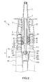
- the convention nasal spray device 100 is shown in Fig. 5 and generally includes a push member 101 with an outlet 101 a and a mount 102 is connected to the push member 101.
- the mount 102 has a suction tube 103 connected thereto which has an annular valve 103a connected thereto.
- a cone-shaped tube 104 is connected to the annular valve 103a of the suction tube 103.
- a bead 107 is located in the cone-shaped tube 104 which has a hole 104a sealed by the bead 107.
- a tube 105 is connected to the cone-shaped tube 104 and a spring 106 is mounted to the tube 105.
- a reception tube 108 accommodates the suction tube 103, the cone-shaped tube 104, the tube 105 and the spring 106 therein in sequence.
- a shoulder 108a is formed on the reception tube 108 and a hose 109 is mounted to the reception tube 108 and stopped by the shoulder 108a.
- the mount 102 is connected to a container which is not shown so as to suck the liquid medicine and spray via the outlet 101 a.
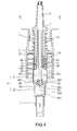
- FIG. 6 Another conventional nasal spray device 200 is disclosed in Fig. 6 and generally includes a push member 201 with an outlet 201 a and a mount 202 is connected to the push member 201.
- the mount 202 has a suction tube 203 which extends through the inner tube 202a in the mount 202 and is connected to the push member 201.
- a sleeve 204 is connected to the other end of the suction tube 203 and a rod 205 is inserted into the sleeve 204.
- the rod 205 has paths 205a defined in the outer periphery thereof and a spring 206 is mounted to the rod 205.
- a bead 207 is located at a distal end of the spring 206 and located in a reception tube 208 which has multiple sections with reduced diameters and a shoulder 208a is formed on the reception tube 208.
- a hose 209 is connected to the reception tube 208.
- the assembly is connected to a container (not shown) by the mount 202 so as to suck the liquid medicine and spray via the outlet 201 a.
- the spring 206 moves the rod 205 to press the bead 207 which seals the shoulder 208a of the reception tube 208 and a gap is defined between the rod 205 and the sleeve 204.
- the liquid medicine in the reception tube 208 flows into the suction tube 203 via the paths 205a and is injected from the outlet 201 a of the push member 201.
- the push member 201 is released, the liquid medicine and air are back to the reception tube 208 via the hose 209.
- the conventional push-type nasal sprays 100, 200 can suck the liquid medicine and spray the liquid medicine from the outlet, the spring 106, 206 and the bead 107, 207 are made by metal and in contact with the liquid directly and may cause chemical change to the liquid medicine and/or be harmful to the users. Besides, the spoiled liquid medicine is difficult to be recycled and may pollute the environment. Furthermore, the conventional nasal spray devices include too many parts and this makes them to be costly.
- the present invention intends to provide a nasal spray device which improves the shortcomings of the conventional nasal spray devices.
- the present invention relates to a nasal spray device and comprises a push member having an outlet from which the liquid medicine is sprayed.
- a tubular portion is connected to a lower end of the push member.
- a mount is connected to a container and has a reception portion connected with the push member.
- a passage is defined centrally through the mount and the tubular portion extends through the passage.
- a rod has a guide tube on a first end thereof and the guide tube extends through the tubular portion.
- a second end of the rod has an insertion and multiple paths are defined axially in the outer surface thereof.
- a flange extends radially outward from the rod and is located between the insertion and the guide tube.
- a protrusion is connected to a side of the flange.
- a resilient member is mounted between the tubular portion of the push member and the mount.
- a block is movably mounted to the first end of the rod and has a reception tube so that the guide tube extends through the reception tube.
- a central hole is defined between the reception tube and the guide tube. The protrusion is engaged with the reception tube to seal the reception tube.
- the resilient member moves the rod back and forth.
- a cylindrical body is a tubular member with gradually reduced diameter and has a top section and a bottom section whose diameter is smaller than that of the top section.
- the top section has a barrel in which the block and the rod are accommodated.
- a tightening valve is formed between the top and bottom sections and the rod snugly extends through the tightening valve.
- the primary object of the present invention is to provide a nasal spray device wherein the resilient member made by metal is received in the cylindrical body and does not contact the liquid medicine which is prevented from being spoiled.
- Another object of the present invention is to provide a nasal spray device wherein the cylindrical body does not have any bead received therein to reduce the number of parts.
- the nasal spray device of the present invention comprises a push member 1, a mount 2, a rod 3, a block 4, a resilient member 5 and a cylindrical body 6, wherein the push member 1 has an outlet 11 defined therein and a tubular portion 12 is connected to a lower end of the push member 1.
- the mount 2 is to be connected to a container 20 and has a reception portion 21 connected with the push member 1 and a passage 22 is defined centrally through the mount 2.
- the tubular portion 12 extends through the passage 22.
- the rod 3 has a guide tube 31 on the first end thereof and the guide tube 31 extends through the tubular portion 12.
- the second end of the rod 3 has an insertion 32 and multiple paths 321 are defined axially in the outer surface thereof.
- a flange 33 extends radially outward from the rod 3 and is located between the insertion 32 and the guide tube 31.
- a protrusion 331 is connected to a side of the flange 33.
- the resilient member 5 is mounted between the tubular portion 12 of the push member 1 and the mount 2 so as to provide a force to move the push member 1 and the rod 3 back.
- the block 4 is movably mounted to the first end of the rod 3 and has a reception tube 41 so that the guide tube 31 extends through the reception tube 41.
- a central hole 42 is defined between the reception tube 41 and the guide tube 31.
- the protrusion 331 is engaged with the reception tube 41 to seal the reception tube 41.
- the resilient member 5 moves the rod 3 back and forth.
- the cylindrical body 6 is a tubular member with gradually reduced diameter and includes a top section 61 and a bottom section 62 whose diameter is smaller than that of the top section 61.
- the top section 61 has a barrel 611 in which the block 4 and the rod 3 are accommodated.
- a tightening valve 63 is formed between the top and bottom sections 61, 62 and the rod 3 snugly extends through the tightening valve 63.
- the cylindrical body 6 has an entrance 621 defined in the lower end thereof and the entrance 621 is located corresponding to the distal end 322.
- the cylindrical body 6 has a connection hole 622 is defined in the lower end thereof so as to be connected with a hose 7 which is inserted into the container 20.
- the tightening valve 63 includes a tightening end 631 which defines an opening at a distal end of the tightening valve 63.
- the tightening end 631 is resiliently mounted to the insertion 32 of the rod 3. After the parts mentioned above are assembled, the mount 2 is connected to the container 20.
- the block 4 is movably mounted to the rod 3 to form opened or closed status by the pressure.
- a gap 8 is defined between the reception tube 41 and the protrusion 331, so that the liquid medicine in the container 20 flows into the tubular portion 12 via the gap 8 and the central hole 42 and is sprayed from the outlet 11 by pushing the push member 1.
Landscapes
- Health & Medical Sciences (AREA)
- Engineering & Computer Science (AREA)
- Public Health (AREA)
- Life Sciences & Earth Sciences (AREA)
- Veterinary Medicine (AREA)
- Anesthesiology (AREA)
- Biomedical Technology (AREA)
- Heart & Thoracic Surgery (AREA)
- Hematology (AREA)
- General Health & Medical Sciences (AREA)
- Animal Behavior & Ethology (AREA)
- Bioinformatics & Cheminformatics (AREA)
- Otolaryngology (AREA)
- Pulmonology (AREA)
- Mechanical Engineering (AREA)
- Infusion, Injection, And Reservoir Apparatuses (AREA)
- Containers And Packaging Bodies Having A Special Means To Remove Contents (AREA)
- Medicinal Preparation (AREA)
Applications Claiming Priority (1)
| Application Number | Priority Date | Filing Date | Title |
|---|---|---|---|
| TW099210663U TWM395485U (en) | 2010-06-04 | 2010-06-04 | Environmentally-friendly nasal-spraying apparatus |
Publications (1)
| Publication Number | Publication Date |
|---|---|
| EP2392373A1 true EP2392373A1 (de) | 2011-12-07 |
Family
ID=44512719
Family Applications (1)
| Application Number | Title | Priority Date | Filing Date |
|---|---|---|---|
| EP11250576A Withdrawn EP2392373A1 (de) | 2010-06-04 | 2011-06-02 | Nasensprayvorrichtung |
Country Status (3)
| Country | Link |
|---|---|
| US (1) | US20110297145A1 (de) |
| EP (1) | EP2392373A1 (de) |
| TW (1) | TWM395485U (de) |
Families Citing this family (2)
| Publication number | Priority date | Publication date | Assignee | Title |
|---|---|---|---|---|
| WO2024105336A1 (fr) | 2022-11-14 | 2024-05-23 | Aptar France Sas | Tete de distribution nasale de produit fluide |
| FR3141859B1 (fr) * | 2022-11-14 | 2025-12-26 | Aptar France Sas | Tête de distribution nasale de produit fluide |
Citations (2)
| Publication number | Priority date | Publication date | Assignee | Title |
|---|---|---|---|---|
| GB2403153A (en) * | 2003-06-26 | 2004-12-29 | Bespak Plc | Hand held nasal dispensing device |
| US20070119869A1 (en) * | 2005-11-25 | 2007-05-31 | Cheng-Yuan Su | Spray head |
Family Cites Families (5)
| Publication number | Priority date | Publication date | Assignee | Title |
|---|---|---|---|---|
| US6685062B1 (en) * | 2002-09-16 | 2004-02-03 | Yon Woo Corporation | Dispenser pump |
| KR100569180B1 (ko) * | 2004-04-29 | 2006-04-10 | 주식회사 종우실업 | 소형 수동식 펌프 |
| US7261222B2 (en) * | 2005-01-24 | 2007-08-28 | Cheng-Yuan Su | Structure for green nozzle |
| US20060186142A1 (en) * | 2005-02-22 | 2006-08-24 | Cheng-Yuan Su | Green nozzle |
| US20060207596A1 (en) * | 2005-03-18 | 2006-09-21 | Fairfield Clinical Trials, Llc | Device and method for delivery of combination nasal medication |
-
2010
- 2010-06-04 TW TW099210663U patent/TWM395485U/zh not_active IP Right Cessation
-
2011
- 2011-06-01 US US13/067,423 patent/US20110297145A1/en not_active Abandoned
- 2011-06-02 EP EP11250576A patent/EP2392373A1/de not_active Withdrawn
Patent Citations (2)
| Publication number | Priority date | Publication date | Assignee | Title |
|---|---|---|---|---|
| GB2403153A (en) * | 2003-06-26 | 2004-12-29 | Bespak Plc | Hand held nasal dispensing device |
| US20070119869A1 (en) * | 2005-11-25 | 2007-05-31 | Cheng-Yuan Su | Spray head |
Also Published As
| Publication number | Publication date |
|---|---|
| US20110297145A1 (en) | 2011-12-08 |
| TWM395485U (en) | 2011-01-01 |
Similar Documents
| Publication | Publication Date | Title |
|---|---|---|
| US9199257B2 (en) | Press type spray head assembly | |
| US8672190B1 (en) | Lotion spray head assembly | |
| US10098384B2 (en) | Atomized liquid storage device and atomizer | |
| US20120305604A1 (en) | Nozzle assembly | |
| US8672192B2 (en) | Push-type nozzle assembly | |
| US20040050858A1 (en) | Double-acting pump for ejecting a product from a container | |
| US20180000156A1 (en) | Atomizer and aerosol generating apparatus | |
| WO2006092590A2 (en) | Dispenser with frangible membrane | |
| EP2703088A1 (de) | Schaumsprühkopfanordnung | |
| US9204766B2 (en) | Press head assembly | |
| US20110303702A1 (en) | Liquid spray head assembly | |
| EP2669015B1 (de) | Schaumsprühkopfanordnung | |
| EP2392373A1 (de) | Nasensprayvorrichtung | |
| US8439233B2 (en) | Spray head assembly | |
| JP2025527056A (ja) | 流体製品吐出装置 | |
| US8561919B2 (en) | Foam spray head assembly | |
| EP3225899A1 (de) | Fettstückverbindungsvorrichtung einer fettpresse | |
| CN103696924B (zh) | 一种连接方便的喷雾泵机构 | |
| JP2020083327A (ja) | 吐出器 | |
| CN103708094B (zh) | 一种起泵快的喷雾泵装置 | |
| CN205345695U (zh) | 一种新型手枪喷雾泵装置 | |
| CN204093622U (zh) | 按压式喷头改进装置 | |
| CN105217166B (zh) | 一种真空瓶 | |
| US20150360245A1 (en) | Spray head assembly | |
| CN102464151A (zh) | 微型手扣式喷雾器 |
Legal Events
| Date | Code | Title | Description |
|---|---|---|---|
| AK | Designated contracting states |
Kind code of ref document: A1 Designated state(s): AL AT BE BG CH CY CZ DE DK EE ES FI FR GB GR HR HU IE IS IT LI LT LU LV MC MK MT NL NO PL PT RO RS SE SI SK SM TR |
|
| AX | Request for extension of the european patent |
Extension state: BA ME |
|
| PUAI | Public reference made under article 153(3) epc to a published international application that has entered the european phase |
Free format text: ORIGINAL CODE: 0009012 |
|
| 17P | Request for examination filed |
Effective date: 20120601 |
|
| 17Q | First examination report despatched |
Effective date: 20180313 |
|
| GRAP | Despatch of communication of intention to grant a patent |
Free format text: ORIGINAL CODE: EPIDOSNIGR1 |
|
| INTG | Intention to grant announced |
Effective date: 20190711 |
|
| STAA | Information on the status of an ep patent application or granted ep patent |
Free format text: STATUS: THE APPLICATION IS DEEMED TO BE WITHDRAWN |
|
| 18D | Application deemed to be withdrawn |
Effective date: 20191122 |