EP2391981B1 - Verfahren und system zur verarbeitung von in echtzeit mit einer medizinischen vorrichtung aufgenommenen bildern - Google Patents
Verfahren und system zur verarbeitung von in echtzeit mit einer medizinischen vorrichtung aufgenommenen bildern Download PDFInfo
- Publication number
- EP2391981B1 EP2391981B1 EP10716406.3A EP10716406A EP2391981B1 EP 2391981 B1 EP2391981 B1 EP 2391981B1 EP 10716406 A EP10716406 A EP 10716406A EP 2391981 B1 EP2391981 B1 EP 2391981B1
- Authority
- EP
- European Patent Office
- Prior art keywords
- images
- buffer
- processing
- loading
- image
- Prior art date
- Legal status (The legal status is an assumption and is not a legal conclusion. Google has not performed a legal analysis and makes no representation as to the accuracy of the status listed.)
- Active
Links
Images


Classifications
-
- G—PHYSICS
- G06—COMPUTING OR CALCULATING; COUNTING
- G06T—IMAGE DATA PROCESSING OR GENERATION, IN GENERAL
- G06T5/00—Image enhancement or restoration
- G06T5/50—Image enhancement or restoration using two or more images, e.g. averaging or subtraction
-
- G—PHYSICS
- G06—COMPUTING OR CALCULATING; COUNTING
- G06T—IMAGE DATA PROCESSING OR GENERATION, IN GENERAL
- G06T3/00—Geometric image transformations in the plane of the image
- G06T3/40—Scaling of whole images or parts thereof, e.g. expanding or contracting
- G06T3/4038—Image mosaicing, e.g. composing plane images from plane sub-images
-
- G—PHYSICS
- G06—COMPUTING OR CALCULATING; COUNTING
- G06T—IMAGE DATA PROCESSING OR GENERATION, IN GENERAL
- G06T3/00—Geometric image transformations in the plane of the image
- G06T3/40—Scaling of whole images or parts thereof, e.g. expanding or contracting
- G06T3/4053—Scaling of whole images or parts thereof, e.g. expanding or contracting based on super-resolution, i.e. the output image resolution being higher than the sensor resolution
-
- G—PHYSICS
- G06—COMPUTING OR CALCULATING; COUNTING
- G06T—IMAGE DATA PROCESSING OR GENERATION, IN GENERAL
- G06T2207/00—Indexing scheme for image analysis or image enhancement
- G06T2207/10—Image acquisition modality
- G06T2207/10068—Endoscopic image
-
- G—PHYSICS
- G06—COMPUTING OR CALCULATING; COUNTING
- G06T—IMAGE DATA PROCESSING OR GENERATION, IN GENERAL
- G06T2207/00—Indexing scheme for image analysis or image enhancement
- G06T2207/30—Subject of image; Context of image processing
- G06T2207/30004—Biomedical image processing
- G06T2207/30028—Colon; Small intestine
-
- G—PHYSICS
- G06—COMPUTING OR CALCULATING; COUNTING
- G06T—IMAGE DATA PROCESSING OR GENERATION, IN GENERAL
- G06T2207/00—Indexing scheme for image analysis or image enhancement
- G06T2207/30—Subject of image; Context of image processing
- G06T2207/30004—Biomedical image processing
- G06T2207/30101—Blood vessel; Artery; Vein; Vascular
- G06T2207/30104—Vascular flow; Blood flow; Perfusion
Definitions
- the invention relates generally to image and video online processing and in particular to a system and method for processing images acquired in real time and especially images acquired through a medical device.
- Patent application US2005207668 presents for example a system to restore in real-time images acquired through a bundle of fiber-optics typically used in endomicroscopy.
- Image and video processing techniques are commonly used in digital video acquisition devices.
- the main purpose of such algorithms is to extract useful information from data. This can mean anything from the simplest visualization enhancement to fully-automatic image-based decision making during surgery.
- the physician's attention might be caught by a specific detail of a video sequence from a given part of a tissue.
- the physician may need said image to be processed.
- Online image processing may notably be run through real time processing or lagged-time processing.
- Real time processing may only be implemented when the processing time is shorter than the time between two images.
- Lagged-time processing may only be implemented when the processing can be completed within a time corresponding to a fixed number of images and requires to launch in parallel several processes.
- Ayache et.al., 9th MICCAI, 01.-06.10.2006 , Copenhagen discloses several complex algorithms used in fibered confocal microscopy, requiring a set of images and which can be performed in lagged-time. As lagged processing may lead to loosing the location of the investigated area on the tissue, common endoscopy systems provide a freeze function which enables to stop on a given image. By freezing upon demand the display, the physician is given more time to analyze the image and make a diagnosis. Freezing the video at the exact time asked by the physician may result in freezing a bad, blurred image.
- US patents US4901143 and US5270810 propose a processing that selects a frozen image which is at the same time a good image and is close to the freezing time asked by the clinician.
- US patents US4901143 and US5270810 also disclose freezing upon demand and address the issue of keeping the information contained in the part of the video sequence that occurs during the freeze period by using two parallel pipelines.
- common techniques are essentially limited by the inner quality or amount of information of the frozen images.
- the present disclosure proposes a method and a system that enables to enhance information retrieval during ongoing video acquisitions.
- embodiments described herein relate to a method for processing images acquired in real time through a medical device, said images being loaded into a buffer, comprising the steps as defined in the independent method claim 1.
- Incremental algorithms are composed of different subroutines that need to be run one after the other.
- the result of each subroutine i.e. an intermediate result
- Incremental algorithms may be for example used to find approximate solutions to problems for which exact solutions cannot be found or cannot be found in a reasonable amount of time such as nondeterministic polynomial-time hard problems for example.
- Each intermediate result may provide an approximate solution and is thus of interest. The more steps can be performed, the closer the approximate solution will be to the exact solution as results are improved from one step to the other.
- Medical devices to acquire images may be any device known to one of ordinary skill in the art including, but not limited to: endomicroscopes, classical endoscopy, High Definition endoscopy, Narrow Band Imaging endoscopy, FICE® endoscopy, double-balloon enteroscopy, zoom endoscopy, Cellzero®, 2D/3D ultrasound imaging or any other non irradiative interventional modality.
- the images processed may be consecutive images from a video sequence or may be a subset of any loaded images.
- embodiments described therein relate to an imaging as defined in the independent apparatus claim 13.
- freeze command refers to stopping the loading into the buffer.
- freeze time refers to the period of time during which the loading is stopped and the processing may be implemented.
- frozen buffer refers to the buffer during the freeze time and so on.
- the present disclosure relates to an image processing system and method that may allow notably computationally intensive video processing, that cannot run in real-time, to be performed online, upon demand and during a given amount of time on a frozen set of images taken from a video stream acquired in real time by an acquisition device.
- a video acquisition device acts as an input for the system.
- Real-time video processing may be performed and the data can be displayed and recorded.
- the data is queued in a buffer which may be a first in first out (FIFO) finite buffer.
- FIFO first in first out
- a freeze command Upon activation of a freeze command, data coming from the video acquisition device may continue in the potential real-time video processing, recording and display pipeline but may not be queued in the FIFO buffer anymore. Namely, the FIFO buffer is frozen. In the meantime, the computationally intensive algorithm of interest may start working on the frozen buffer and may continue until the freeze command is deactivated.
- Computationally intensive algorithm are generally incremental algorithm and are processed in several steps, each steps giving intermediate results.
- incremental algorithm may be iterative meaning that after some initialization, an intermediate result is enhanced at each iteration.
- the proposed system may display the result and record it.
- each intermediate result has to be evaluated based on at least one of a quantitative criteria, a subjective criteria and a human criteria in order to know if the processing has to be carried on.
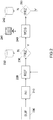
- FIG. 1 illustrates several steps of a method according to an embodiment of the present disclosure.
- the video processing system receives an image stream from the video acquisition device (step 110).
- the image stream may be processed in real-time in step 120. Both the original data and the real-time processed one may be displayed (step 121) and stored (step 122).
- a freeze test is then performed (step 130). If the system is not in frozen mode (arrow N), the images are loaded into a buffer (step 140). If the system is turned to freeze mode (arrow Y), new images do not enter the buffer anymore and the computationally intensive algorithm of interest starts processing the set of buffered images (step 150). Computationally intensive algorithms may work in an incremental manner and provide intermediate results at each completion of a step.
- the system may check whether it is still in freeze mode or not. If the system is still in freeze mode, a new processing step may be launched., otherwise the algorithm is stopped and the images loading into the buffer is resumed (step 140). In both cases, intermediate results of the algorithm may also be displayed (step 151) and/or stored (step 152).
- the display may be done on a motion picture display and the like. Several such devices may be used to display the different video streams. The different streams might also be combined onto a single display device. Simple juxtaposition or advanced image fusion techniques might be used.
- the storage and the FIFO buffer may be located on a local or remote disk storage, a memory device and the like.
- the original or real-time processed images are queued in a bounded FIFO buffer. If the FIFO buffer is not yet at full capacity, the new images are simply appended to the FIFO buffer. If the FIFO buffer is already full, the new images will replace the oldest one.
- the actual capacity bound of the FIFO buffer may be chosen by the user or by the system or may simply be defined by hardware constraints.
- a user monitors the original or real-time processed image stream displayed on a display device.
- a button that may for example be located on the acquisition device, triggering the freeze mode. Going back to the default not frozen mode might be triggered for example by releasing the button, pushing another button, automatically after a given amount of time and the like.
- Freeze mode might also be automatically or semi-automatically activated or deactivated based on a decision made by another processing algorithm.
- Such algorithm may be for example a motion detection algorithm as disclosed in US patents US4901143 and US5270810 . These algorithms may be coupled in order to activate the freeze mode when a motion on an image stream goes from smooth to erratic.
- a computationally intensive algorithm simply aims at extracting useful information from a frozen images set buffer. Thanks to a continuing increase in the available practical computing power, the complexity of algorithms available for image processing tasks has become higher. Advanced processing is now possible in real-time or with some latency. Despite these advances, there will always be a gap between the actual available computing power and the computing power required to run some interesting cutting-edge processing algorithms on the fly. Because of hardware constraints, extracting an interesting information from a set of images may not always be completed within the time that separates two frames coming from an acquisition device. In an embodiment of the invention, being able to run a cutting-edge computationally-intensive processing algorithm during video acquisition may allow the development of new applications. Users are interested in the possibility of using selectively such a cutting-edge algorithm that may not be run in real-time nor in lagged-time.
- a computationally intensive algorithm may use a frozen set of image to produce a new enhanced image or a new enhanced set of images and does it in an iterative manner.
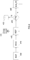
- FIG. 2 illustrates several steps of a method implementing video sequence mosaicing incremental algorithm according to an embodiment of the present disclosure.
- Vercauteren et al. showed potential benefits of using dedicated video mosaicing techniques to widen the field of view by aligning and fusing many consecutive images from a video sequence, for example in the context of endomicroscopy.
- This mosaicing algorithm may not be run in real-time and works by iteratively refining a mosaic image. It can thus clearly benefit from the present invention.
- the images loaded into the buffer are frozen (step 200), meaning that the loading of images into the buffer is stopped.
- the loaded images also referred to as frozen images
- This step might for example consist of automatically choosing a subset of the images in the FIFO buffer so that the remainder of the mosaicing algorithm may assume that all consecutive frames in the subset are overlapping. This may be done by performing a fast but rough initial registration. A threshold on a quantitative evaluation of the quality of the rough registration can be used to define the subset of overlapping images. Afterwards the following steps may be performed in an iterative manner. Registration results are refined (step 220). A freeze test is then performed (step 230) in order to determine if the system is still in freeze mode. If the system has been switched back to the default not frozen mode (arrow N), registration results might be stored and the processing is halted (step 232). Otherwise, a mosaic image is constructed (step 240) and displayed (step 241).
- a freeze test is then performed (step 250). If the system has been switched back to the default not frozen mode (arrow N), the reconstructed mosaic might be stored (step 242) and the processing is halted. Otherwise, a new refinement step is performed and the process is performed in an iterative manner.
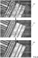
- Figure 3 is a display illustrating successive results of a video sequence mosaicing incremental algorithm according to an embodiment of the present invention. It highlights incremental improvement of an image mosaic as computed, during a freeze time period.
- the mosaicing algorithm may be run on a plurality of frames (for example 26 frames) of a healthy human colon acquired in vivo by means of endomicroscopy.
- Initial alignment may be rather rough and the image mosaic may be a simple image overlay (image 300).
- image 310 a globally consistent alignment may computed
- image 320 a state-of-the-art image fusion technique
- This may be followed by a mosaic that takes into account motion distortion that alters endomicroscopy (image 320).
- a mosaic compensating for non-rigid deformations due to interactions between the imaged soft tissue and an optical probe of an endomicroscope may be constructed (image 330).
- FIG 4 is a diagram representing schematically steps of a method implementing a super-resolution incremental algorithm according to an embodiment of the present disclosure.
- Patent Application US20070273930 showed potential benefit of creating a high resolution image from a set of shifted images, for example in the context of endomicroscopy. Besides a mechanical device presented there to shift images, super-resolution might also be done from uncontrolled motion images. As presented by Irani and Peleg, typical super-resolution algorithms are iterative in nature and require a large amount of processing power.
- the images loaded into the buffer are frozen (step 400).
- the freezed set of images may be then registered onto a given reference (step 410).
- the alignment might be imposed by the mechanical constraints as in US Patent Application US20070273930 or might be the results of some image registration algorithm. From this alignment a high-resolution image is constructed in step 420, and displayed in step 421. A freeze test is then performed in step 430. If the system has been switched back to the default not frozen mode (arrow N), the reconstructed high-resolution image might be stored (step 422) and the processing is halted. Otherwise (arrow Y), low-resolution images are simulated from the current high-resolution image and knowledge of the imaging system in step 440. The error between the simulated low-resolution images and the actual original low-resolution images is used to improve the current high-resolution image by a back-projection technique, going back to the step of constructing an high resolution image.
- Figure 5 is a display illustrating successive results of a super-resolution incremental algorithm according to an embodiment of the present disclosure.
- An image from a frozen set of images is chosen and upsampled to provide an approximation of an high-resolution image (image 500).
- a first and second successive results of iterative improvements are shown (respectively images 510 and 520).
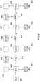
- FIG. 6 is a diagram representing schematically steps of a method implementing blood velocity measurement incremental algorithm according to an embodiment of the present disclosure.
- US Patent Application US20080045848 showed potential benefits of measuring blood velocity from a set of images, for example in the context of endomicroscopy.
- blood velocity computation might be done by a pipeline of processing algorithms that work on a set of consecutive images. The complete processing may require a large amount of processing power. Even though the pipeline is not strictly speaking iterative, it is still incremental. Results of each subcomponent of this pipeline can be of interest to the user.
- the images loaded into the buffer are frozen (step 600).
- a region of interest within one given image may be automatically tracked and stabilized across the set of frozen images (step 610) resulting in a set of stabilized images.
- the initial region of interest might be defined by the user, automatically selected by another processing algorithm such as a salient region detector, or might consist of the complete image.
- Stabilization results might be stored (step 612) and/or displayed (step 611).
- a freeze test may be performed (step 620). If the system has been switched back to the default not frozen mode (arrow N), processing is simply halted. Otherwise (arrow Y), a mean image is computed from the stabilized region of interest sequence to improve the signal to noise ratio and a vessel segmentation algorithm is performed on the mean stabilized image (step 630).
- Segmentation results might be displayed (step 631) and stored (step 632).
- a freeze test may be performed (step 640). If the system has been switched back to the default not frozen mode (arrow N), processing is simply halted. Otherwise (arrow Y), segmentation is propagated to all images in the set of stabilized images (step 650). Segmentation propagation might be displayed (step 651) and/or stored (step 652).
- a freeze test may be performed (step 660). If the system has been switched back to the default not frozen mode (arrow N), processing is simply halted. Otherwise (arrow Y), blood velocity is computed within the detected vessels by a dedicated processing algorithm such as a medial line correlation method (step 670). Finally the estimated blood velocity is displayed (step 671) and/or stored (step 672).
- Figure 7 is a display illustrating successive results of a blood velocity measurement incremental algorithm. It highlights progression through blood velocity measurement processing pipeline as computed by the previously described possible embodiment.
- a given region of interest is tracked and stabilized through a sequence in a frozen buffer (images 710, 720 and 730).
- a stabilized mean region of interest image is shown and used to segment the vessel structure present in the region of interest (images 740 and 750).
- the segmentation is propagated to the stabilized region of interest sequence (images 760, 770 and 780).
- a graph representing the estimation of blood velocity though the freezed sequence as a function of time is displayed (image 790).
- endoscopic and endomicroscopic images are displayed to a user on separated displays.
- the microscopic imaging probe is visible on the macroscopic endoscopic view. It may be of clinical interest to fuse the two sources of information and show the microscopic images within their macroscopic context.
- the image processing to fuse the flow of macroscopic and microscopic images cannot be run in real time.
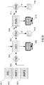
- Figure 8 illustrates several steps of a method used to fuse images.
- a first flow of images may be acquired on a first acquisition device and a second flow of images may be acquired on a second acquisition device.
- the first and second acquisition devices may be mechanically coupled so as to acquire images of the same object under observation.
- the first and second acquisition devices may be an endoscope and an endomicroscope inserted in an accessory channel of the endoscope so as to acquire simultaneously microscopic and macroscopic images.
- images acquired by the endomicroscope may be loaded in a first buffer (step 802) while images acquired by the endoscope (second acquisition device) may be loaded in a second buffer (step 803).
- images from the first and second acquisition devices may be displayed.
- the user may select, during the ongoing acquisition, one or more interesting images of the second flow of images (macroscopic images from the endoscope) associated with one or more images of the first flow of images (microscopic images from the endomicroscope).
- the associated images of the first flow of images may temporally correspond to the selected images of the second flow of images.
- the selection may be carried out for example by clicking on a button (step 801).
- the system may store timings, called interest signals, enabling to retrieve the selected images from the buffer.
- interesting images among the first and second set of images may be selected automatically by an algorithm among the images stored in the first and second buffers. For example, one image out of ten may be automatically selected in the first and second buffers.
- the user may also select images among the first or second sets of images loaded in the first and second buffers. For example, the user may review the sets of images loaded in the first and/or second buffers by displaying said images on a display unit. For example, an image from the first or second sets of images loaded in the frozen buffers may be selected when the image is displayed for more than a predetermined amount of time.
- the user may decide that an image processing should be run. Therefore, the user may for example press a freeze button, triggering the freeze mode. Entering the freeze mode may stop the loading of images in the first and second buffers.
- the system may perform a detection step (step 805) on one of the selected image.
- the detection may comprise detecting the endomicroscopic probe on one selected image of the second set of images (i.e. macroscopic images) to obtain a macroscopic processed image.
- the detection result may be displayed (step 806).
- a freeze test may then be performed (step 807). If the system is not in freeze mode, the detection results may be stored (step 808).
- the system proceeds and fuses the image of the first set of image (microscopic image) temporally corresponding to the macroscopic selected processed image (step 809).
- the fused result may be displayed (step 810).
- the microscopic image may be positioned next to the position at which the endomicroscopic probe has been detected.
- advanced texture mapping technique may be used.
- a freeze test may performed (step 811) and the system may either store the fusion result and bails out (812) or proceeds according to the above mentioned process with another selected image.
- a plurality of microscopic images may be fused on a macroscopic image (step 905). This may be performed by propagating information resulting from one or more fusions between macroscopic and microscopic corresponding images onto a main macroscopic image. Endoscopic images have a large field of view compared to endomicroscopic images. Therefore, several microscopic images may potentially be fused on a macroscopic image. Fusing a supplementary microscopic image on a macroscopic image may preliminary require that the supplementary microscopic image is fused to a corresponding second macroscopic image according to the previously described scheme.
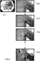
- Figure 9 is a display illustrating successive results of a fusion algorithm according to an embodiment of the present disclosure.
- An endoscopic image of interest is selected for processing (step 902), the endomiscroscopic probe is detected and the tip of the probe is displayed (step 903).
- a fusion according to the previously described scheme is performed to show the microscopic image associated to the endoscopic image (step 901) in the macroscopic context (step 904). Further processing steps are then performed and step 905 illustrates the result of fusing several endomicroscopic images of interest on a macroscopic image.
- the images referred to in the description may be multi spectral images acquired on a plurality of collection channels of an acquisition device. Accordingly, the scope of the invention should be limited only by the attached claims.
Landscapes
- Physics & Mathematics (AREA)
- General Physics & Mathematics (AREA)
- Engineering & Computer Science (AREA)
- Theoretical Computer Science (AREA)
- Endoscopes (AREA)
- Image Analysis (AREA)
- Microscoopes, Condenser (AREA)
- Closed-Circuit Television Systems (AREA)
- Apparatus For Radiation Diagnosis (AREA)
- Image Processing (AREA)
Claims (15)
- Verfahren für das online-Verarbeiten von Bildern, umfassend die Schritte aus:(a) Erfassen (100) von Bildern mittels einer medizinischen Einrichtung in Echtzeit;(b) Anzeigen der Bilder in Echtzeit (121);(c) Laden (140) der Bilder in einen Pufferspeicher, der einen Satz von Bildern erhält;(d) Anhalten des Ladens der Bilder in den Pufferspeicher basierend auf einer Bewertung der in Echtzeit angezeigten Bilder,(e) Verarbeiten (150) des geladenen Satzes von Bildern unter Verwendung eines inkrementellen Algorithmus, wobei der inkrementelle Algorithmus aus unterschiedlichen Unterprogrammen besteht, die nacheinander ausgeführt werden müssen und welche Zwischenergebnisse bereitstellen;(f) Sukzessives Anzeigen der durch Verarbeitung des Satzes von Bildern erhaltenen Zwischenergebnisse (151),(g) Anhalten der Verarbeitung basierend auf einer Bewertung der Zwischenergebnisse und Wiederaufnehmen des Ladens erfasster Bilder in einen Pufferspeicher;wobei Erfassen (100) und Anzeigen der Bilder in Echtzeit (121) beim Anhalten des Ladens (140) von Bildern in den Ladespeicher fortgesetzt wird.
- Verfahren nach Anspruch 1, wobei die erfassten Bilder aus einer Videosequenz abgeleitet sind und wobei das Verarbeiten (150) iteratives Ausrichten und Verschmelzen aufeinanderfolgender Bilder umfasst, um das Sichtfeld zu erweitern.
- Verfahren nach Anspruch 1, wobei die erfassten Bilder verschobene Bilder sind und das Verarbeiten (150) iteratives Registrieren der Bilder umfasst, um ein hochauflösendes Bild zu erhalten.
- Verfahren nach Anspruch 1, wobei die erfassten Bilder aus einer Videosequenz abgeleitet sind, die Blutgefäße darstellt und das Verarbeiten (150) die Blutgeschwindigkeit berechnet.
- Verfahren nach Anspruch 1, wobei das Laden (140) automatisch angehalten wird.
- Verfahren nach Anspruch 5, wobei das Laden basieren auf einem Bewegungserkennungsalgorithmus angehalten wird.
- Verfahren nach Anspruch 1, wobei die Bewertung der Zwischenergebnisse von einem Benutzer oder automatisch verwaltet wird.
- Verfahren nach Anspruch 1, wobei der Pufferspeicher ein FIFO-Pufferspeicher ist.
- Verfahren nach Anspruch 1, wobei die Zwischenergebnisse auf einer Speichereinrichtung gespeichert werden.
- Verfahren nach Anspruch 1, wobei die Zwischenergebnisse der Verarbeitung mit den in Echtzeit angezeigten Bildern zusammengeführt werden.
- Verfahren nach Anspruch 1, wobei die medizinische Einrichtung ein faseroptisches Konfokalmikroskop ist.
- Verfahren nach Anspruch 1, wobei die medizinische Einrichtung eine erste Erfassungseinrichtung und eine zweite Erfassungseinrichtung umfasst und der Pufferspeicher einen ersten Pufferspeicher und einen zweiten Pufferspeicher umfasst, um entsprechend die auf den ersten und zweiten Erfassungseinrichtungen erfassten Bilder zu laden, und wobei das Verarbeiten Verschmelzen eines oder mehrerer in den ersten Pufferspeicher geladener Bilder mit einem in den zweiten Pufferspeicher geladenen Bildes umfasst.
- Bildgebendes System, umfassend:eine medizinische Einrichtung zum Erfassen von Bildern in Echtzeit,eine Anzeigeeinrichtung zum Anzeigen der Bilder in Echtzeit,eine Speichereinrichtung, die einen Pufferspeicher zum Laden der Bilder umfasst,einen Freeze-Befehl, um das Laden der Bilder in den Pufferspeicher bei Aktivierung anzuhalten,einen Prozessor zum Verarbeiten der Bilder,wobei:bei Aktivierung des Freeze-Befehls:der Prozessor geladene Bilder unter Verwendung eines inkrementellen Algorithmus verarbeitet, wobei der inkrementelle Algorithmus aus unterschiedlichen Unterprogrammen besteht, die nacheinander ausgeführt werden müssen und welche Zwischenergebnisse bereitstellen,die Anzeigeeinrichtung sukzessive Zwischenergebnisse des Algorithmus anzeigt, unddie medizinische Einrichtung und die Anzeigeeinrichtung bei Deaktivierung des Freeze-Befehls damit fortfahren, Bilder in Echtzeit zu erfassen und anzuzeigen, undbasierend auf einer Bewertung besagter Zwischenergebnisse das Laden der Bilder in den Pufferspeicher bei Deaktivierung des Freeze-Befehls wiederaufgenommen wird.
- System nach Anspruch 13, wobei das Anhalten des Ladens in den Pufferspeicher auf einer Bewertung der in Echtzeit angezeigten Bilder basiert.
- System nach Anspruch 13, wobei die medizinische Einrichtung ein fiberoptisches Konfokalmikroskop ist.
Applications Claiming Priority (2)
| Application Number | Priority Date | Filing Date | Title |
|---|---|---|---|
| US14872409P | 2009-01-30 | 2009-01-30 | |
| PCT/IB2010/000608 WO2010086751A2 (en) | 2009-01-30 | 2010-01-29 | Method and system for processing images acquired in real time through a medical device |
Publications (2)
| Publication Number | Publication Date |
|---|---|
| EP2391981A2 EP2391981A2 (de) | 2011-12-07 |
| EP2391981B1 true EP2391981B1 (de) | 2017-04-05 |
Family
ID=42292215
Family Applications (1)
| Application Number | Title | Priority Date | Filing Date |
|---|---|---|---|
| EP10716406.3A Active EP2391981B1 (de) | 2009-01-30 | 2010-01-29 | Verfahren und system zur verarbeitung von in echtzeit mit einer medizinischen vorrichtung aufgenommenen bildern |
Country Status (7)
| Country | Link |
|---|---|
| US (1) | US8600134B2 (de) |
| EP (1) | EP2391981B1 (de) |
| JP (1) | JP2012516176A (de) |
| AU (1) | AU2010209422B2 (de) |
| CA (1) | CA2751097C (de) |
| ES (1) | ES2630045T3 (de) |
| WO (1) | WO2010086751A2 (de) |
Families Citing this family (24)
| Publication number | Priority date | Publication date | Assignee | Title |
|---|---|---|---|---|
| JP5636247B2 (ja) * | 2010-10-06 | 2014-12-03 | Hoya株式会社 | 電子内視鏡用プロセッサ及び電子内視鏡装置 |
| JP5601970B2 (ja) * | 2010-10-26 | 2014-10-08 | Hoya株式会社 | 電子内視鏡用プロセッサ及び電子内視鏡装置 |
| JP6112624B2 (ja) | 2011-08-02 | 2017-04-12 | ビューズアイキュー インコーポレイテッドViewsIQ Inc. | デジタル顕微鏡撮像の装置及び方法 |
| US11768689B2 (en) | 2013-08-08 | 2023-09-26 | Movidius Limited | Apparatus, systems, and methods for low power computational imaging |
| US9146747B2 (en) | 2013-08-08 | 2015-09-29 | Linear Algebra Technologies Limited | Apparatus, systems, and methods for providing configurable computational imaging pipeline |
| CN105612554B (zh) | 2013-10-11 | 2019-05-10 | 冒纳凯阿技术公司 | 用于表征通过视频医疗设备获取的图像的方法 |
| US10248761B2 (en) | 2015-01-07 | 2019-04-02 | Derm Mapper, LLC | Computerized system and method for recording and tracking dermatological lesions |
| CN109310296A (zh) | 2016-04-06 | 2019-02-05 | 爱丁堡大学董事会 | 内窥镜成像装置及方法 |
| GB201611819D0 (en) | 2016-07-07 | 2016-08-17 | Univ Court Of The Univ Of Edinburgh The | Imaging method and apparatus |
| GB201707239D0 (en) | 2017-05-05 | 2017-06-21 | Univ Edinburgh | Optical system and method |
| JP7373335B2 (ja) * | 2019-09-18 | 2023-11-02 | 富士フイルム株式会社 | 医用画像処理装置、プロセッサ装置、内視鏡システム、医用画像処理装置の作動方法、及びプログラム |
| US12042241B2 (en) | 2021-03-31 | 2024-07-23 | Moon Surgical Sas | Co-manipulation surgical system having automated preset robot arm configurations |
| US11812938B2 (en) | 2021-03-31 | 2023-11-14 | Moon Surgical Sas | Co-manipulation surgical system having a coupling mechanism removeably attachable to surgical instruments |
| US11844583B2 (en) | 2021-03-31 | 2023-12-19 | Moon Surgical Sas | Co-manipulation surgical system having an instrument centering mode for automatic scope movements |
| US12167900B2 (en) | 2021-03-31 | 2024-12-17 | Moon Surgical Sas | Co-manipulation surgical system having automated preset robot arm configurations |
| US11832909B2 (en) | 2021-03-31 | 2023-12-05 | Moon Surgical Sas | Co-manipulation surgical system having actuatable setup joints |
| US12178418B2 (en) | 2021-03-31 | 2024-12-31 | Moon Surgical Sas | Co-manipulation surgical system having a coupling mechanism removeably attachable to surgical instruments |
| EP4312857B1 (de) | 2021-03-31 | 2025-09-03 | Moon Surgical SAS | Chirurgisches system mit co-manipulation zur verwendung mit chirurgischen instrumenten zur durchführung laparoskopischer chirurgie |
| US11819302B2 (en) | 2021-03-31 | 2023-11-21 | Moon Surgical Sas | Co-manipulation surgical system having user guided stage control |
| KR102553001B1 (ko) | 2021-10-05 | 2023-07-10 | 한국과학기술연구원 | 인공지능 기반의 이미지의 허니컴 아티팩트 제거 방법 및 장치 |
| CN114863427B (zh) * | 2022-05-12 | 2025-02-07 | 长沙协大生物科技有限公司 | 一种基于图像融合的体液显微视频精益表达方法 |
| US12370001B2 (en) | 2023-01-09 | 2025-07-29 | Moon Surgical Sas | Co-manipulation surgical system having automated user override detection |
| US11986165B1 (en) | 2023-01-09 | 2024-05-21 | Moon Surgical Sas | Co-manipulation surgical system for use with surgical instruments for performing laparoscopic surgery while estimating hold force |
| US11832910B1 (en) | 2023-01-09 | 2023-12-05 | Moon Surgical Sas | Co-manipulation surgical system having adaptive gravity compensation |
Family Cites Families (16)
| Publication number | Priority date | Publication date | Assignee | Title |
|---|---|---|---|---|
| US4901143A (en) | 1988-02-16 | 1990-02-13 | Olympus Optical Co., Ltd. | Electronic endoscope system provided with a means of imaging frozen pictures having few picture image smears |
| JP2519302B2 (ja) | 1988-08-19 | 1996-07-31 | オリンパス光学工業株式会社 | 画像フリ―ズ装置 |
| JP2953079B2 (ja) | 1991-02-14 | 1999-09-27 | 富士写真光機株式会社 | 電子内視鏡装置 |
| JPH04341232A (ja) | 1991-03-11 | 1992-11-27 | Olympus Optical Co Ltd | 電子内視鏡システム |
| JP3078045B2 (ja) | 1991-07-24 | 2000-08-21 | オリンパス光学工業株式会社 | 画像フリーズ処理装置 |
| JPH07246184A (ja) | 1994-03-09 | 1995-09-26 | Fuji Photo Optical Co Ltd | 面順次式撮像装置 |
| US5492125A (en) * | 1995-02-10 | 1996-02-20 | University Of Washington | Ultrasound signal processing apparatus |
| US6975898B2 (en) * | 2000-06-19 | 2005-12-13 | University Of Washington | Medical imaging, diagnosis, and therapy using a scanning single optical fiber system |
| US6678395B2 (en) * | 2001-03-22 | 2004-01-13 | Robert N. Yonover | Video search and rescue device |
| US20040189641A1 (en) | 2001-08-03 | 2004-09-30 | Peter Stephenson | Method and apparatus for determining intersections of a particular line with cells in a lattice |
| FR2842628B1 (fr) | 2002-07-18 | 2004-09-24 | Mauna Kea Technologies | "procede de traitement d'une image acquise au moyen d'un guide compose d'une pluralite de fibres optiques" |
| AU2003298919A1 (en) * | 2002-12-04 | 2004-06-23 | Conformis, Inc. | Fusion of multiple imaging planes for isotropic imaging in mri and quantitative image analysis using isotropic or near-isotropic imaging |
| US6847728B2 (en) | 2002-12-09 | 2005-01-25 | Sarnoff Corporation | Dynamic depth recovery from multiple synchronized video streams |
| FR2864631B1 (fr) | 2003-12-31 | 2006-04-14 | Mauna Kea Technologies | Procede et systeme de super-resolution d'images confocales acquises a travers un guide d'image, et dispositif utilise pour la mise en oeuvre d'un tel procede |
| FR2868279B1 (fr) | 2004-04-02 | 2006-06-09 | Mauna Kea Technologies Soc Par | Procede et systeme de mesure de vitesse du flux sanguin |
| US7859679B2 (en) | 2005-05-31 | 2010-12-28 | The General Hospital Corporation | System, method and arrangement which can use spectral encoding heterodyne interferometry techniques for imaging |
-
2010
- 2010-01-29 JP JP2011547001A patent/JP2012516176A/ja active Pending
- 2010-01-29 US US13/144,518 patent/US8600134B2/en active Active
- 2010-01-29 WO PCT/IB2010/000608 patent/WO2010086751A2/en not_active Ceased
- 2010-01-29 ES ES10716406.3T patent/ES2630045T3/es active Active
- 2010-01-29 AU AU2010209422A patent/AU2010209422B2/en active Active
- 2010-01-29 CA CA2751097A patent/CA2751097C/en active Active
- 2010-01-29 EP EP10716406.3A patent/EP2391981B1/de active Active
Non-Patent Citations (1)
| Title |
|---|
| None * |
Also Published As
| Publication number | Publication date |
|---|---|
| CA2751097C (en) | 2017-02-28 |
| US8600134B2 (en) | 2013-12-03 |
| JP2012516176A (ja) | 2012-07-19 |
| EP2391981A2 (de) | 2011-12-07 |
| ES2630045T3 (es) | 2017-08-17 |
| US20110274325A1 (en) | 2011-11-10 |
| AU2010209422B2 (en) | 2015-06-18 |
| WO2010086751A2 (en) | 2010-08-05 |
| AU2010209422A1 (en) | 2011-09-01 |
| WO2010086751A3 (en) | 2010-09-23 |
| CA2751097A1 (en) | 2010-08-05 |
Similar Documents
| Publication | Publication Date | Title |
|---|---|---|
| EP2391981B1 (de) | Verfahren und system zur verarbeitung von in echtzeit mit einer medizinischen vorrichtung aufgenommenen bildern | |
| AU2019431299A1 (en) | AI systems for detecting and sizing lesions | |
| EP2453408B1 (de) | Verarbeitungsverfahren von Röntgenbildern zur Erkennung einer Stenose | |
| US8306606B2 (en) | Medical imaging apparatus, ultrasonic imaging apparatus, magnetic resonance imaging apparatus, medical image processing apparatus, and medical image processing method | |
| EP3005232A2 (de) | Rekonstruktion von bildern aus einer in-vivo-multikamerakapsel | |
| US9398857B2 (en) | Diagnostic imaging apparatus and method of operating the same | |
| JP2013009956A (ja) | 医用画像表示装置及び医用画像診断装置 | |
| CN104684454A (zh) | 图像处理装置、程序和图像处理方法 | |
| EP2902961B1 (de) | Bildverarbeitungsvorrichtung, programm und bildverarbeitungsverfahren | |
| JP6772123B2 (ja) | 画像処理装置、画像処理方法、画像処理システムおよびプログラム | |
| US20150202021A1 (en) | Method for processing images of interventional radiology | |
| KR102526434B1 (ko) | 병변 진단 장치 및 그 방법 | |
| JP2008237839A (ja) | 画像解析システム、及び画像解析プログラム | |
| US11056149B2 (en) | Medical image storage and reproduction apparatus, method, and program | |
| CN113554628A (zh) | 图像处理方法、装置及计算机可读存储介质 | |
| JP7100505B2 (ja) | 画像処理装置、画像処理装置の作動方法、及び画像処理装置の作動プログラム | |
| CN114079753A (zh) | 一种图像同步缓存显示方法、系统、装置和存储介质 | |
| JP5005980B2 (ja) | 内視鏡装置 | |
| JP2007268154A (ja) | 循環器用x線システム | |
| JP4814647B2 (ja) | 内視鏡の画像信号記録装置 | |
| Trivisonne | Image-guided interactive simulation for endovascular gurgery | |
| WO2024236795A1 (ja) | 画像処理装置、画像処理方法および画像処理プログラム | |
| JP5980567B2 (ja) | 画像処理装置、プログラム及び画像処理装置の作動方法 | |
| Soper et al. | New approaches to Bladder-Surveillance endoscopy | |
| WO2020261955A1 (ja) | 診断支援プログラム、診断支援システム及び診断支援方法 |
Legal Events
| Date | Code | Title | Description |
|---|---|---|---|
| PUAI | Public reference made under article 153(3) epc to a published international application that has entered the european phase |
Free format text: ORIGINAL CODE: 0009012 |
|
| 17P | Request for examination filed |
Effective date: 20110816 |
|
| AK | Designated contracting states |
Kind code of ref document: A2 Designated state(s): AT BE BG CH CY CZ DE DK EE ES FI FR GB GR HR HU IE IS IT LI LT LU LV MC MK MT NL NO PL PT RO SE SI SK SM TR |
|
| RIC1 | Information provided on ipc code assigned before grant |
Ipc: G06T 5/00 20060101ALI20111124BHEP Ipc: G06T 1/00 20060101AFI20111124BHEP Ipc: A61B 1/00 20060101ALI20111124BHEP |
|
| DAX | Request for extension of the european patent (deleted) | ||
| RIN1 | Information on inventor provided before grant (corrected) |
Inventor name: PERCHANT, AYMERIC Inventor name: SAVOIRE, NICOLAS Inventor name: VERCAUTEREN, TOM Inventor name: LACOMBE, FRANCOIS |
|
| REG | Reference to a national code |
Ref country code: DE Ref legal event code: R079 Ref document number: 602010041278 Country of ref document: DE Free format text: PREVIOUS MAIN CLASS: G06T0001000000 Ipc: G06T0003400000 |
|
| RIC1 | Information provided on ipc code assigned before grant |
Ipc: G06T 5/50 20060101ALI20160713BHEP Ipc: G06T 3/40 20060101AFI20160713BHEP |
|
| GRAP | Despatch of communication of intention to grant a patent |
Free format text: ORIGINAL CODE: EPIDOSNIGR1 |
|
| INTG | Intention to grant announced |
Effective date: 20160920 |
|
| GRAJ | Information related to disapproval of communication of intention to grant by the applicant or resumption of examination proceedings by the epo deleted |
Free format text: ORIGINAL CODE: EPIDOSDIGR1 |
|
| STAA | Information on the status of an ep patent application or granted ep patent |
Free format text: STATUS: REQUEST FOR EXAMINATION WAS MADE |
|
| GRAR | Information related to intention to grant a patent recorded |
Free format text: ORIGINAL CODE: EPIDOSNIGR71 |
|
| GRAS | Grant fee paid |
Free format text: ORIGINAL CODE: EPIDOSNIGR3 |
|
| STAA | Information on the status of an ep patent application or granted ep patent |
Free format text: STATUS: GRANT OF PATENT IS INTENDED |
|
| INTC | Intention to grant announced (deleted) | ||
| GRAA | (expected) grant |
Free format text: ORIGINAL CODE: 0009210 |
|
| STAA | Information on the status of an ep patent application or granted ep patent |
Free format text: STATUS: THE PATENT HAS BEEN GRANTED |
|
| INTG | Intention to grant announced |
Effective date: 20170223 |
|
| AK | Designated contracting states |
Kind code of ref document: B1 Designated state(s): AT BE BG CH CY CZ DE DK EE ES FI FR GB GR HR HU IE IS IT LI LT LU LV MC MK MT NL NO PL PT RO SE SI SK SM TR |
|
| REG | Reference to a national code |
Ref country code: GB Ref legal event code: FG4D |
|
| REG | Reference to a national code |
Ref country code: CH Ref legal event code: EP |
|
| REG | Reference to a national code |
Ref country code: AT Ref legal event code: REF Ref document number: 882445 Country of ref document: AT Kind code of ref document: T Effective date: 20170415 |
|
| REG | Reference to a national code |
Ref country code: IE Ref legal event code: FG4D |
|
| REG | Reference to a national code |
Ref country code: DE Ref legal event code: R096 Ref document number: 602010041278 Country of ref document: DE |
|
| REG | Reference to a national code |
Ref country code: NL Ref legal event code: MP Effective date: 20170405 |
|
| REG | Reference to a national code |
Ref country code: ES Ref legal event code: FG2A Ref document number: 2630045 Country of ref document: ES Kind code of ref document: T3 Effective date: 20170817 |
|
| REG | Reference to a national code |
Ref country code: LT Ref legal event code: MG4D |
|
| REG | Reference to a national code |
Ref country code: AT Ref legal event code: MK05 Ref document number: 882445 Country of ref document: AT Kind code of ref document: T Effective date: 20170405 |
|
| PG25 | Lapsed in a contracting state [announced via postgrant information from national office to epo] |
Ref country code: NL Free format text: LAPSE BECAUSE OF FAILURE TO SUBMIT A TRANSLATION OF THE DESCRIPTION OR TO PAY THE FEE WITHIN THE PRESCRIBED TIME-LIMIT Effective date: 20170405 |
|
| PG25 | Lapsed in a contracting state [announced via postgrant information from national office to epo] |
Ref country code: LT Free format text: LAPSE BECAUSE OF FAILURE TO SUBMIT A TRANSLATION OF THE DESCRIPTION OR TO PAY THE FEE WITHIN THE PRESCRIBED TIME-LIMIT Effective date: 20170405 Ref country code: GR Free format text: LAPSE BECAUSE OF FAILURE TO SUBMIT A TRANSLATION OF THE DESCRIPTION OR TO PAY THE FEE WITHIN THE PRESCRIBED TIME-LIMIT Effective date: 20170706 Ref country code: NO Free format text: LAPSE BECAUSE OF FAILURE TO SUBMIT A TRANSLATION OF THE DESCRIPTION OR TO PAY THE FEE WITHIN THE PRESCRIBED TIME-LIMIT Effective date: 20170705 Ref country code: HR Free format text: LAPSE BECAUSE OF FAILURE TO SUBMIT A TRANSLATION OF THE DESCRIPTION OR TO PAY THE FEE WITHIN THE PRESCRIBED TIME-LIMIT Effective date: 20170405 Ref country code: FI Free format text: LAPSE BECAUSE OF FAILURE TO SUBMIT A TRANSLATION OF THE DESCRIPTION OR TO PAY THE FEE WITHIN THE PRESCRIBED TIME-LIMIT Effective date: 20170405 Ref country code: AT Free format text: LAPSE BECAUSE OF FAILURE TO SUBMIT A TRANSLATION OF THE DESCRIPTION OR TO PAY THE FEE WITHIN THE PRESCRIBED TIME-LIMIT Effective date: 20170405 |
|
| PG25 | Lapsed in a contracting state [announced via postgrant information from national office to epo] |
Ref country code: IS Free format text: LAPSE BECAUSE OF FAILURE TO SUBMIT A TRANSLATION OF THE DESCRIPTION OR TO PAY THE FEE WITHIN THE PRESCRIBED TIME-LIMIT Effective date: 20170805 Ref country code: SE Free format text: LAPSE BECAUSE OF FAILURE TO SUBMIT A TRANSLATION OF THE DESCRIPTION OR TO PAY THE FEE WITHIN THE PRESCRIBED TIME-LIMIT Effective date: 20170405 Ref country code: BG Free format text: LAPSE BECAUSE OF FAILURE TO SUBMIT A TRANSLATION OF THE DESCRIPTION OR TO PAY THE FEE WITHIN THE PRESCRIBED TIME-LIMIT Effective date: 20170705 Ref country code: LV Free format text: LAPSE BECAUSE OF FAILURE TO SUBMIT A TRANSLATION OF THE DESCRIPTION OR TO PAY THE FEE WITHIN THE PRESCRIBED TIME-LIMIT Effective date: 20170405 Ref country code: PL Free format text: LAPSE BECAUSE OF FAILURE TO SUBMIT A TRANSLATION OF THE DESCRIPTION OR TO PAY THE FEE WITHIN THE PRESCRIBED TIME-LIMIT Effective date: 20170405 |
|
| REG | Reference to a national code |
Ref country code: DE Ref legal event code: R097 Ref document number: 602010041278 Country of ref document: DE |
|
| REG | Reference to a national code |
Ref country code: FR Ref legal event code: PLFP Year of fee payment: 9 |
|
| PG25 | Lapsed in a contracting state [announced via postgrant information from national office to epo] |
Ref country code: SK Free format text: LAPSE BECAUSE OF FAILURE TO SUBMIT A TRANSLATION OF THE DESCRIPTION OR TO PAY THE FEE WITHIN THE PRESCRIBED TIME-LIMIT Effective date: 20170405 Ref country code: DK Free format text: LAPSE BECAUSE OF FAILURE TO SUBMIT A TRANSLATION OF THE DESCRIPTION OR TO PAY THE FEE WITHIN THE PRESCRIBED TIME-LIMIT Effective date: 20170405 Ref country code: CZ Free format text: LAPSE BECAUSE OF FAILURE TO SUBMIT A TRANSLATION OF THE DESCRIPTION OR TO PAY THE FEE WITHIN THE PRESCRIBED TIME-LIMIT Effective date: 20170405 Ref country code: RO Free format text: LAPSE BECAUSE OF FAILURE TO SUBMIT A TRANSLATION OF THE DESCRIPTION OR TO PAY THE FEE WITHIN THE PRESCRIBED TIME-LIMIT Effective date: 20170405 Ref country code: EE Free format text: LAPSE BECAUSE OF FAILURE TO SUBMIT A TRANSLATION OF THE DESCRIPTION OR TO PAY THE FEE WITHIN THE PRESCRIBED TIME-LIMIT Effective date: 20170405 |
|
| PLBE | No opposition filed within time limit |
Free format text: ORIGINAL CODE: 0009261 |
|
| STAA | Information on the status of an ep patent application or granted ep patent |
Free format text: STATUS: NO OPPOSITION FILED WITHIN TIME LIMIT |
|
| PG25 | Lapsed in a contracting state [announced via postgrant information from national office to epo] |
Ref country code: SM Free format text: LAPSE BECAUSE OF FAILURE TO SUBMIT A TRANSLATION OF THE DESCRIPTION OR TO PAY THE FEE WITHIN THE PRESCRIBED TIME-LIMIT Effective date: 20170405 |
|
| 26N | No opposition filed |
Effective date: 20180108 |
|
| PG25 | Lapsed in a contracting state [announced via postgrant information from national office to epo] |
Ref country code: SI Free format text: LAPSE BECAUSE OF FAILURE TO SUBMIT A TRANSLATION OF THE DESCRIPTION OR TO PAY THE FEE WITHIN THE PRESCRIBED TIME-LIMIT Effective date: 20170405 |
|
| REG | Reference to a national code |
Ref country code: CH Ref legal event code: PL |
|
| PG25 | Lapsed in a contracting state [announced via postgrant information from national office to epo] |
Ref country code: LU Free format text: LAPSE BECAUSE OF NON-PAYMENT OF DUE FEES Effective date: 20180129 |
|
| REG | Reference to a national code |
Ref country code: IE Ref legal event code: MM4A |
|
| REG | Reference to a national code |
Ref country code: BE Ref legal event code: MM Effective date: 20180131 |
|
| PG25 | Lapsed in a contracting state [announced via postgrant information from national office to epo] |
Ref country code: BE Free format text: LAPSE BECAUSE OF NON-PAYMENT OF DUE FEES Effective date: 20180131 Ref country code: CH Free format text: LAPSE BECAUSE OF NON-PAYMENT OF DUE FEES Effective date: 20180131 Ref country code: LI Free format text: LAPSE BECAUSE OF NON-PAYMENT OF DUE FEES Effective date: 20180131 |
|
| PG25 | Lapsed in a contracting state [announced via postgrant information from national office to epo] |
Ref country code: IE Free format text: LAPSE BECAUSE OF NON-PAYMENT OF DUE FEES Effective date: 20180129 |
|
| REG | Reference to a national code |
Ref country code: DE Ref legal event code: R082 Ref document number: 602010041278 Country of ref document: DE Representative=s name: DOMPATENT VON KREISLER SELTING WERNER - PARTNE, DE |
|
| PG25 | Lapsed in a contracting state [announced via postgrant information from national office to epo] |
Ref country code: MC Free format text: LAPSE BECAUSE OF FAILURE TO SUBMIT A TRANSLATION OF THE DESCRIPTION OR TO PAY THE FEE WITHIN THE PRESCRIBED TIME-LIMIT Effective date: 20170405 |
|
| PG25 | Lapsed in a contracting state [announced via postgrant information from national office to epo] |
Ref country code: MT Free format text: LAPSE BECAUSE OF NON-PAYMENT OF DUE FEES Effective date: 20180129 |
|
| PG25 | Lapsed in a contracting state [announced via postgrant information from national office to epo] |
Ref country code: TR Free format text: LAPSE BECAUSE OF FAILURE TO SUBMIT A TRANSLATION OF THE DESCRIPTION OR TO PAY THE FEE WITHIN THE PRESCRIBED TIME-LIMIT Effective date: 20170405 |
|
| PG25 | Lapsed in a contracting state [announced via postgrant information from national office to epo] |
Ref country code: HU Free format text: LAPSE BECAUSE OF FAILURE TO SUBMIT A TRANSLATION OF THE DESCRIPTION OR TO PAY THE FEE WITHIN THE PRESCRIBED TIME-LIMIT; INVALID AB INITIO Effective date: 20100129 Ref country code: PT Free format text: LAPSE BECAUSE OF FAILURE TO SUBMIT A TRANSLATION OF THE DESCRIPTION OR TO PAY THE FEE WITHIN THE PRESCRIBED TIME-LIMIT Effective date: 20170405 |
|
| PG25 | Lapsed in a contracting state [announced via postgrant information from national office to epo] |
Ref country code: MK Free format text: LAPSE BECAUSE OF NON-PAYMENT OF DUE FEES Effective date: 20170405 Ref country code: CY Free format text: LAPSE BECAUSE OF FAILURE TO SUBMIT A TRANSLATION OF THE DESCRIPTION OR TO PAY THE FEE WITHIN THE PRESCRIBED TIME-LIMIT Effective date: 20170405 |
|
| PGFP | Annual fee paid to national office [announced via postgrant information from national office to epo] |
Ref country code: DE Payment date: 20241224 Year of fee payment: 16 |
|
| PGFP | Annual fee paid to national office [announced via postgrant information from national office to epo] |
Ref country code: ES Payment date: 20250210 Year of fee payment: 16 |
|
| PGFP | Annual fee paid to national office [announced via postgrant information from national office to epo] |
Ref country code: IT Payment date: 20241230 Year of fee payment: 16 |
|
| PGFP | Annual fee paid to national office [announced via postgrant information from national office to epo] |
Ref country code: GB Payment date: 20251218 Year of fee payment: 17 |
|
| PGFP | Annual fee paid to national office [announced via postgrant information from national office to epo] |
Ref country code: FR Payment date: 20251222 Year of fee payment: 17 |