EP2391926B1 - Mouvement horloger - Google Patents
Mouvement horloger Download PDFInfo
- Publication number
- EP2391926B1 EP2391926B1 EP09801456.6A EP09801456A EP2391926B1 EP 2391926 B1 EP2391926 B1 EP 2391926B1 EP 09801456 A EP09801456 A EP 09801456A EP 2391926 B1 EP2391926 B1 EP 2391926B1
- Authority
- EP
- European Patent Office
- Prior art keywords
- barrel
- drum
- timepiece movement
- frame
- bearing
- Prior art date
- Legal status (The legal status is an assumption and is not a legal conclusion. Google has not performed a legal analysis and makes no representation as to the accuracy of the status listed.)
- Active
Links
Images


Classifications
-
- G—PHYSICS
- G04—HOROLOGY
- G04B—MECHANICALLY-DRIVEN CLOCKS OR WATCHES; MECHANICAL PARTS OF CLOCKS OR WATCHES IN GENERAL; TIME PIECES USING THE POSITION OF THE SUN, MOON OR STARS
- G04B1/00—Driving mechanisms
- G04B1/10—Driving mechanisms with mainspring
- G04B1/16—Barrels; Arbors; Barrel axles
-
- G—PHYSICS
- G04—HOROLOGY
- G04B—MECHANICALLY-DRIVEN CLOCKS OR WATCHES; MECHANICAL PARTS OF CLOCKS OR WATCHES IN GENERAL; TIME PIECES USING THE POSITION OF THE SUN, MOON OR STARS
- G04B33/00—Calibers
- G04B33/12—Calibers for extremely long running times
Definitions
- the present invention relates to a watch movement comprising a frame carrying a barrel arranged to maintain the oscillations of a mechanical oscillator via a finishing train.
- the barrel comprises a drum, housing a barrel spring whose one end is engaged with a barrel shaft pivotally mounted in two bearings, at least one of which is carried by the frame, the drum defining a first level in the direction of the thickness of the watch movement.
- the finishing train comprises a first mobile arranged in engagement with a transmission member integral in rotation with the barrel shaft.
- the cylinder outlet is provided by its drum, which has a toothing meshing with a first mobile of the finishing train adjacent to the drum.
- two barrels are mounted coaxial having their respective springs connected to each other via a common barrel shaft.
- a first of the two barrels has a drum having a toothing by which the two springs can be recharged from a winding.
- the third barrel is disposed laterally to the first two and has a drum having a toothing arranged in engagement with the toothing of the drum of the second of the coaxial barrels. Therefore, the output of this third barrel, to maintain the oscillations of a mechanical oscillator movement, is formed from its shaft.
- the latter is integral in rotation with a transmission wheel having a peripheral toothing whose characteristics are similar to those of the drum of the third barrel.
- the transmission of the force provided by the barrel springs is carried out conventionally to a first mobile of a finishing train, adjacent to the third barrel and, a pinion is arranged in engagement with the transmission wheel.
- this patent proposes to use only a third barrel disposed laterally to the first two, to leave free a certain volume in superposition of the third barrel, whose thickness is slightly less than the thickness of a barrel.
- the patent CH 51982 proposes a solution to a single barrel in which the energy of the mainspring is transmitted, via the barrel shaft, to a first mobile of the finishing gear rotatably mounted on the frame of the movement along an axis of rotation. superimposed on the barrel drum in the direction of the thickness of the movement to define a second level.
- a main object of the present invention is to overcome the drawbacks mentioned above, by proposing a watch movement with a comfortable power reserve while offering dimensions. and ensuring smooth and stable transmission of the barrel spring force to the gear train, ensuring better movement in conventional constructions, even in the event of shocks.
- Another object of the present invention is to provide such a movement in which space is kept available to allow the addition of a possible complication mechanism.
- the present invention more particularly relates to a watch movement as defined in claim 1.
- the diameter of the barrel can be enlarged with reference to a conventional construction, allowing to accommodate a spring of greater development to increase the power reserve of the movement, while preserving the maximum gear train finishing disturbances which could have their origin in inadvertent movements of the barrel drum, especially in case of shocks.
- the two bearings of the barrel shaft are carried by the frame of the movement, possibly being disposed on either side of the drum.
- the barrel shaft is completely isolated from its drum and the movements that would present the latter in such a case would not be transmitted to the shaft and thus to the gear train, unlike the constructions of the prior art.
- the frame comprises an annular shoulder whose inner periphery is integral with a bearing of the barrel shaft and the outer periphery is integral with the bearing of the barrel drum.
- the bearing of the barrel drum has the shape of a ring comprising at least one sliding surface on which slides a surface of the barrel drum.
- finishing gear comprises additional mobiles essentially disposed in the second level so as to release the useful space in the first level between the barrel and the mechanical oscillator. This useful space can thus be used to house a complication mechanism.
- the first mobile is a center mobile on which pivots at least one drive member intended to be integral with a central body for indicating a time information.
- the barrel can extend beyond the center of the movement and offer a significant power reserve.
- such a construction can be implemented with a conventional finishing gear in direct contact with the barrel outlet, in other words without requiring the addition of intermediate springs, sources of yield loss.
- the present invention also relates to a timepiece equipped with such a watch movement.
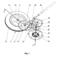
- the figure 1 represents a simplified perspective view, on the platinum side, of a watch movement according to a preferred embodiment of the present invention.
- This watch movement comprises a barrel 1 housing a mainspring (numerical reference 2, on the figure 2 ) connected to a barrel shaft 4 at a first end thereof and to a barrel drum 5 at its second end.
- the barrel is further closed by a lid 6, driven on the drum, while the latter is provided with a toothing 8 at its periphery.
- the present invention provides that a transmission member is mounted on the barrel shaft being rotationally integral therewith.
- This transmission member has the shape of a wheel 10 on the figure 1 .
- the transmission wheel 10 is arranged in engagement with the pinion (reference numeral 12 on the figure 2 ) a center wheel 13 whose wheel 14 is engaged with a pinion 15 of average.
- a wheel of average 16 integral in rotation with the pinion 15, is arranged in engagement with the pinion (reference numeral 18 on the figure 2 ) of a mobile seconds 19 whose wheel 20 is engaged with the pinion 21 of an escape wheel 22.
- the escape wheel cooperates, in a conventional manner, with an anchor 23 arranged in kinematic relationship with a pendulum 24 forming a mechanical oscillator with a hairspring 25.
- the finishing gear train which has just been described makes it possible, typically, to transmit the energy stored by the mainspring to the mechanical oscillator of the watch movement in order to maintain the oscillations thereof.
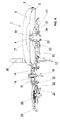
- the figure 2 represents a sectional view of the watch movement as described in connection with the figure 1 , made along the line II-II passing through the axes of the different motions of the movement.
- This view makes it possible to better illustrate the advantage provided by the structure according to the present invention in terms of size in the watch movement.
- the barrel 1 defines a first level in the direction of the thickness of the movement while the center mobile 13 is superimposed on it by defining a second level.
- the other mobiles of the work train are essentially located in the second level while the mechanical oscillator is located partly in the first level and partly in the second level.
- a useful space is released in the first level, that is to say on the bridge side, between the cylinder and the balance spring to possibly allow the addition of a mechanism of complication (not shown) such as a chronograph mechanism or display phases of the Moon.
- the watch movement as shown is intended, by way of non-limiting illustration, to cause a central referral indicating the current time by mounting the corresponding drive members (floor and hour wheel, not visible) on the center mobile tree.
- the structure of the movement according to the present invention allows the use of a cylinder of large radius, capable of housing a mainspring such that the movement can have a large power reserve, which can extend especially beyond- beyond the center of the movement, in contrast to conventional center display movements.
- a first end of the barrel spring 2 is secured to a plug 27 while its second end is integral with the barrel drum 5.
- the barrel shaft 4, carrying the transmission wheel 10 is mounted between two bearings 28, 29, or stones, driven into elements of the frame, respectively a plate (not shown) and a barrel bridge 30.
- a plate not shown
- a barrel bridge 30 Such a structure guarantees excellent regularity in the meshing of the transmission wheel 10 with the pinion 12 of the center wheel 13 and therefore a good walk of the watch movement.
- the plug 27 is mounted coaxially with the barrel shaft 4 so as to drive it in rotation throughout the development of the barrel spring.
- the suspension of the barrel drum 5 is ensured by the cooperation of its center with first and second rings 32, 33, integral with the barrel bridge 30.
- the drum is retained axially, in one direction, by the first ring 32 and, in the other direction, by the second ring 33.
- the first ring 32 could, alternatively, be integral with the drum or be omitted. In the latter case, it would be possible to reduce the thickness of the second ring 33 in such a way that the axial retention of the drum is ensured, on the one hand, by the second ring 33 and, on the other hand, directly by the bridge of barrel 30, without departing from the scope of the invention.
- the second ring 33 is positioned on the barrel bridge 30 by means of an annular shoulder 35, simultaneously forming a housing for a bearing 29 of the barrel shaft 4, being held in place by means of screws 36, illustrative non-limiting.
- a winding mechanism is provided for charging the mainspring, of which only the winding stem 38 has been shown in the figures for clarity.
- a conventional stop device is also provided in the winding mechanism to prevent a discharge of the mainspring when the winding stem is not actuated by a user to recharge.
- the winding mechanism is arranged to reload the barrel spring by the intermediate cylinder drum, more precisely by its teeth 8.
- the stop device is arranged to prevent the barrel drum to rotate in the direction of rotation opposite to the direction corresponding to the load of the mainspring.
- the figure 3 represents a simplified and partially exploded perspective view, on the bridge side, of the watch movement of the figure 1 , and illustrates a preferred construction detail.
- the bung 27 has two lugs 40 intended to cooperate with a disk 41 of the barrel shaft in which two flats 42 have been formed.
- the bung 27 and the barrel shaft 4 have between them a certain free angular clearance, that is to say when the barrel spring is not in place or is completely discharged.
- the lugs are disposed in abutment against the flats of the barrel shaft to drive the latter in rotation.
- the expected angular clearance limits the risk of damage to the gear train in case of rupture of the mainspring.
- the disassembly of the barrel 1 is simplified thanks to this construction.
- the barrel bridge 30 Once the barrel bridge 30 has been removed, the barrel 1 can simply be pulled out of motion with the plug 27, as shown in FIG. figure 3 , while its shaft 4 remains housed in the bearing 29 which is arranged in the plate, the transmission wheel remaining in engagement with the center wheel 13.
- the figure 4 represents a view, in simplified perspective and partially cut, illustrating an alternative embodiment of the watch movement according to the present invention.
- the mounting of the barrel 1 is reversed with respect to the embodiment of the preceding figures.
- the barrel drum 5 is located on the platen side while a barrel bridge 43, interposed between the drum and the transmission wheel 10, is provided to ensure the suspension of the barrel in a manner similar to what has been has been previously described in relation to the ring 33.
- the barrel bridge 43 may also comprise a bearing for the plug 27.
- Such a structure makes it possible to modify the typical location of the barrel bridge to place it between the barrel and the plate and thus make the barrel completely visible from the bottom of a timepiece that would be equipped with the corresponding movement, offering a completely new aspect to this timepiece.
- the insulation of the barrel shaft is here less effective than in the case of the first embodiment of the Figures 1 to 3 , the fact that the shaft is guided by a bearing mounted on an element of the frame of the movement still allows to reduce the impact of untimely movements of the drum on the smooth running of the mechanical oscillator movement.
- the second bearing of the barrel shaft housed in the cover can be mounted elsewhere, in a frame member, on the same side as the first bearing. reference to the drum. This would provide a level of insulation of the barrel shaft equivalent to that of the first embodiment
Landscapes
- Physics & Mathematics (AREA)
- General Physics & Mathematics (AREA)
- Electric Clocks (AREA)
Description
- La présente invention concerne un mouvement horloger comportant un bâti portant un barillet agencé pour entretenir les oscillations d'un oscillateur mécanique par l'intermédiaire d'un rouage de finissage. De manière conventionnelle, le barillet comprend un tambour, logeant un ressort de barillet dont une première extrémité est en prise avec un arbre de barillet monté pivotant dans deux paliers dont l'un au moins est porté par le bâti, le tambour définissant un premier niveau dans le sens de l'épaisseur du mouvement horloger. Plus particulièrement, le rouage de finissage comporte un premier mobile agencé en prise avec un organe de transmission solidaire en rotation de l'arbre de barillet.
- De manière générale, la sortie du barillet est assurée par son tambour, celui-ci présentant une denture engrenant avec un premier mobile du rouage de finissage adjacent au tambour.
- Toutefois, une construction du type mentionné plus haut est divulguée dans le brevet
EP 1 582 943 B1 qui concerne un mouvement horloger dans lequel trois barillets sont montés en série pour offrir une réserve de marche importante. - Dans ce mouvement, deux barillets sont montés coaxiaux en ayant leurs ressorts respectifs liés l'un à l'autre par l'intermédiaire d'un arbre de barillet commun. Un premier des deux barillets présente un tambour comportant une denture par laquelle les deux ressorts peuvent être rechargés à partir d'un remontoir. Le troisième barillet est disposé latéralement aux deux premiers et présente un tambour comportant une denture agencée en prise avec la denture du tambour du second des barillets coaxiaux. De ce fait, la sortie de ce troisième barillet, permettant d'entretenir les oscillations d'un oscillateur mécanique du mouvement, est ménagée à partir de son arbre. Ce dernier est solidaire en rotation d'une roue de transmission présentant une denture périphérique dont les caractéristiques sont similaires à celles du tambour du troisième barillet.
- Ainsi, la transmission de la force fournie par les ressorts de barillets est effectuée classiquement à un premier mobile d'un rouage de finissage, adjacent au troisième barillet et, dont un pignon est agencé en prise avec la roue de transmission.
- Le fait de disposer deux barillets superposés dans le mouvement induit un accroissement contraignant de l'épaisseur du mouvement correspondant, en référence à un mouvement ne comportant qu'un seul barillet. Aussi, ce brevet propose de n'utiliser qu'un troisième barillet disposé latéralement au deux premiers, pour laisser libre un certain volume en superposition du troisième barillet, dont l'épaisseur est légèrement inférieure à l'épaisseur d'un barillet. Une telle construction permet de disposer d'une réserve de marche confortable tout en ayant la liberté de prévoir une complication dont le mécanisme peut être agencé dans l'espace laissé libre.
- Cependant, il faut noter que cette solution, consistant à augmenter le volume du mouvement horloger pour y ménager de l'espace disponible, ne convient pas à la réalisation de pièces d'horlogerie à réserve de marche importante mais de faible épaisseur.
- Le brevet
CH 51982 - Toutefois, la construction proposée dans ce document n'est pas satisfaisante du point de vue de la stabilité, notamment en cas de chocs. En effet, le tambour de barillet est pivoté directement sur l'arbre de barillet et repose simplement dans une portée ménagée dans une platine du mouvement. Ainsi, en cas de choc, le tambour peut heurter l'arbre de barillet et nuire à la précision de marche de l'oscillateur.
- Un but principal de la présente invention est de pallier les inconvénients mentionnés ci-dessus, en proposant un mouvement horloger présentant une réserve de marche confortable tout en proposant des dimensions restreintes et en assurant une transmission régulière et stable de la force du ressort de barillet au rouage de finissage, garantissant une meilleure marche du mouvement que dans les constructions conventionnelles, même en cas de chocs.
- Un autre but de la présente invention est de proposer un tel mouvement dans lequel de l'espace est maintenu disponible pour permettre l'ajout d'un éventuel mécanisme de complication.
- A cet effet, la présente invention concerne plus particulièrement un mouvement horloger tel que défini dans la revendication 1.
- Grâce à ces caractéristiques, le diamètre du barillet peut être agrandi en référence à une construction conventionnelle, permettant d'y loger un ressort de plus grand développement pour augmenter la réserve de marche du mouvement, tout en préservant au maximum le rouage de finissage des perturbations qui pourraient trouver leur origine dans des mouvements intempestifs du tambour de barillet, notamment en cas de chocs.
- Suivant une variante de réalisation avantageuse, les deux paliers de l'arbre de barillet sont portés par le bâti du mouvement, en étant éventuellement disposés de part et d'autre du tambour. Dans ce cas, l'arbre de barillet est complètement isolé de son tambour et les mouvements que présenteraient ce dernier en pareil cas ne seraient pas transmis à l'arbre et donc au rouage de finissage, contrairement aux constructions de l'art antérieur.
- Selon l'invention, le bâti comporte un épaulement annulaire dont la périphérie interne est solidaire d'un palier de l'arbre de barillet et la périphérie externe est solidaire du palier du tambour de barillet.
- En particulier, on peut prévoir que le palier du tambour de barillet présente la forme d'une bague comprenant au moins une surface de glissement sur laquelle glisse une surface du tambour de barillet.
- Ces caractéristiques permettent avantageusement d'obtenir une construction relativement compacte tout en assurant une bonne qualité de rotation de l'arbre et du tambour de barillet.
- Par ailleurs, la présente invention prévoit également que le rouage de finissage comporte des mobiles supplémentaires essentiellement disposés dans le second niveau de manière à libérer de l'espace utile dans le premier niveau, entre le barillet et l'oscillateur mécanique. Cet espace utile peut ainsi être mis à profit pour loger un mécanisme de complication.
- Selon une variante de réalisation préférée, le premier mobile est un mobile de centre sur lequel pivote au moins un organe d'entraînement destiné à être solidaire d'un organe central d'indication d'une information horaire.
- Grâce à ces caractéristiques, le barillet peut s'étendre au-delà du centre du mouvement et proposer une réserve de marche importante. En outre, une telle construction peut être mise en oeuvre avec un rouage de finissage conventionnel en prise directe avec la sortie du barillet, autrement dit sans nécessiter l'ajout de renvois intermédiaires, sources de perte de rendement.
- La présente invention concerne également une pièce d'horlogerie équipée d'un tel mouvement horloger.
- D'autres caractéristiques et avantages de la présente invention apparaîtront plus clairement à la lecture de la description détaillée d'un mode de réalisation préféré qui suit, faite en référence aux dessins annexés donnés à titre d'exemples non limitatifs et dans lesquels:
- la
figure 1 représente une vue en perspective simplifiée, du côté platine, d'un mouvement horloger selon un mode de réalisation préféré de la présente invention; - la
figure 2 représente une vue en coupe simplifiée suivant la ligne brisée II-II de lafigure 1 ; - la
figure 3 représente une vue en perspective simplifiée et partiellement éclatée, du côté ponts, du mouvement horloger de lafigure 1 , et - la
figure 4 représente une vue en perspective simplifiée et partiellement coupée d'un mouvement horloger selon une variante de réalisation de la présente invention. - La
figure 1 représente une vue en perspective simplifiée, du côté platine, d'un mouvement horloger selon un mode de réalisation préféré de la présente invention. - Ce mouvement horloger comporte un barillet 1 logeant un ressort de barillet (référence numérique 2, sur la
figure 2 ) relié à un arbre de barillet 4, par une première de ses extrémités, et à un tambour de barillet 5, par sa seconde extrémité. Le barillet est en outre fermé par un couvercle 6, chassé sur le tambour, tandis que ce dernier est muni d'une denture 8 à sa périphérie. - La présente invention prévoit qu'un organe de transmission est monté sur l'arbre de barillet en étant solidaire en rotation de celui-ci. Cet organe de transmission présente la forme d'une roue 10 sur la
figure 1 . - La roue de transmission 10 est agencée en prise avec le pignon (référence numérique 12 sur la
figure 2 ) d'un mobile de centre 13 dont la roue 14 est en prise avec un pignon 15 de moyenne. Une roue de moyenne 16, solidaire en rotation du pignon 15, est agencée en prise avec le pignon (référence numérique 18 sur lafigure 2 ) d'un mobile de secondes 19 dont la roue 20 est en prise avec le pignon 21 d'une roue d'échappement 22. La roue d'échappement coopère, de manière conventionnelle, avec une ancre 23 agencée en relation cinématique avec un balancier 24 formant un oscillateur mécanique avec un spiral 25. - Ainsi, hormis sa disposition particulière, le rouage de finissage qui vient d'être décrit permet typiquement de transmettre l'énergie emmagasinée par le ressort de barillet à l'oscillateur mécanique du mouvement horloger pour en entretenir les oscillations.
- La
figure 2 représente une vue en coupe du mouvement horloger tel que décrit en relation avec lafigure 1 , réalisée suivant la ligne II-II passant par les axes des différents mobiles du mouvement. - Cette vue permet de mieux illustrer l'avantage procuré par la structure selon la présente invention en termes d'encombrement dans le mouvement horloger.
- En effet, il ressort clairement de la
figure 2 que le barillet 1 définit un premier niveau dans le sens de l'épaisseur du mouvement tandis que le mobile de centre 13 lui est superposé en définissant un second niveau. En outre, il apparaît également que les autres mobiles du rouage de finissage sont essentiellement situés dans le second niveau tandis que l'oscillateur mécanique est situé en partie dans le premier niveau et en partie dans le second niveau. - Grâce à cet agencement particulier des mobiles du rouage de finissage, un espace utile est libéré dans le premier niveau, c'est-à-dire côté ponts, entre le barillet et le balancier spiral pour permettre éventuellement l'ajout d'un mécanisme de complication (non représenté) comme par exemple un mécanisme de chronographe ou d'affichage des phases de la Lune.
- De plus, le mouvement horloger tel que représenté est destiné, à titre illustratif non limitatif, à entraîner un aiguillage central d'indication de l'heure courante par montage des organes d'entraînement correspondants (chaussée et roue des heures, non visibles) sur l'arbre du mobile de centre. Ainsi, on constate sur la
figure 2 que la structure du mouvement selon la présente invention permet l'utilisation d'un barillet de rayon important, susceptible de loger un ressort de barillet tel que le mouvement puisse disposer d'une grande réserve de marche, qui peut notamment s'étendre au-delà du centre du mouvement, contrairement aux mouvements conventionnels à affichage au centre. - Par ailleurs, l'assemblage particulier du barillet 1, selon la présente invention, est également visible en détail sur la
figure 2 . - Une première extrémité du ressort de barillet 2 est solidaire d'une bonde 27 tandis que sa seconde extrémité est solidaire du tambour de barillet 5.
- L'arbre de barillet 4, portant la roue de transmission 10, est monté entre deux paliers 28, 29, ou pierres, chassés dans des éléments du bâti, respectivement une platine (non représentée) et un pont de barillet 30. Une telle structure garantit une excellente régularité dans l'engrènement de la roue de transmission 10 avec le pignon 12 du mobile de centre 13 et donc une bonne marche du mouvement horloger.
- La bonde 27 est montée coaxiale à l'arbre de barillet 4 de manière à l'entraîner en rotation tout au long du développement du ressort de barillet.
- La suspension du tambour de barillet 5 est assurée par la coopération de son centre avec des première et seconde bagues 32, 33, solidaires du pont de barillet 30. Le tambour est retenu axialement, dans un sens, par la première bague 32 et, dans l'autre sens, par la seconde bague 33.
- La première bague 32 pourrait, en alternative, être solidaire du tambour ou encore être omise. Dans ce dernier cas, on pourrait diminuer l'épaisseur de la seconde bague 33 de telle manière que le maintien axial du tambour soit assuré, d'une part, par la seconde bague 33 et, d'autre part, directement par le pont de barillet 30, sans sortir du cadre de l'invention.
- La seconde bague 33 est positionnée sur le pont de barillet 30 au moyen d'un épaulement annulaire 35, formant simultanément un logement pour un palier 29 de l'arbre de barillet 4, en étant maintenu en place au moyen de vis 36, à titre illustratif non limitatif.
- Grâce à ces caractéristiques particulières, un bon positionnement du tambour de barillet 5 est garanti et tout défaut de positionnement, de dimensionnement ou dans le mouvement du tambour de barillet n'a aucune incidence sur la marche du mouvement étant donné que le tambour et l'arbre du barillet sont montés sur le bâti du mouvement indépendamment l'un de l'autre. En outre, la suspension du barillet est améliorée, notamment par diminution des risques de battement et en cas de choc. La construction proposée pour la suspension du barillet présente en outre une compacité remarquable en référence à l'efficacité obtenue.
- Bien entendu, un mécanisme de remontage est prévu pour charger le ressort de barillet, dont seule la tige de remontoir 38 a été représentée sur les figures pour plus de clarté. Un dispositif d'arrêt conventionnel, du type cliquet, est également prévu dans le mécanisme de remontage pour empêcher une décharge du ressort de barillet lorsque la tige de remontoir n'est pas actionnée par un utilisateur pour le recharger. Il convient de noter qu'étant donné la structure particulière du mouvement horloger selon la présente invention, notamment le fait que la fonction de sortie du barillet est assurée par son arbre, le mécanisme de remontage est agencé pour recharger le ressort de barillet par l'intermédiaire du tambour de barillet, plus précisément par sa denture 8. De même, le dispositif d'arrêt est agencé pour empêcher le tambour de barillet de tourner dans le sens de rotation opposé au sens correspondant à la charge du ressort de barillet.
- La
figure 3 représente une vue en perspective simplifiée et partiellement éclatée, du côté ponts, du mouvement horloger de lafigure 1 , et illustre un détail de construction préféré. - Plus précisément, il ressort de la
figure 3 que la bonde 27 présente deux ergots 40 destinés à coopérer avec un disque 41 de l'arbre de barillet dans lequel deux méplats 42 ont été ménagés. Ainsi, la bonde 27 et l'arbre de barillet 4 présentent entre eux un certain jeu angulaire à vide, c'est-à-dire lorsque le ressort de barillet n'est pas en place ou est complètement déchargé. En fonctionnement normal du mouvement, les ergots sont disposés en butée contre les méplats de l'arbre de barillet pour entraîner ce dernier en rotation. Par ailleurs, le jeu angulaire prévu permet de limiter les risques de dommages subis par le rouage de finissage en cas de rupture du ressort de barillet. - On notera également que le démontage du barillet 1 est simplifié grâce à cette construction. Une fois le pont de barillet 30 retiré, le barillet 1 peut être simplement tiré hors du mouvement avec la bonde 27, comme représenté sur la
figure 3 , tandis que son arbre 4 reste logé dans le palier 29 qui est agencé dans la platine, la roue de transmission restant en prise avec le mobile de centre 13. - La
figure 4 représente une vue, en perspective simplifiée et partiellement coupée, illustrant une variante de réalisation du mouvement horloger selon la présente invention. - Suivant cette variante de réalisation, le montage du barillet 1 est inversé par rapport au mode de réalisation des figures précédentes. En effet, le tambour de barillet 5 est situé du côté de la platine tandis qu'un pont de barillet 43, interposé entre le tambour et la roue de transmission 10, est prévu pour assurer la suspension du barillet de manière similaire à ce qui a été décrit précédemment en relation avec la bague 33. De manière avantageuse, le pont de barillet 43 peut également comprendre un palier pour la bonde 27.
- Une autre différence notable en référence au mode de réalisation précédent réside dans le montage de l'arbre de barillet 4. Celui-ci est pivoté, d'une part, dans une pierre 29 logée dans la platine et, d'autre part, dans une pierre 44 logée dans le couvercle 6 du barillet.
- Une telle structure permet de modifier l'emplacement typique du pont de barillet pour le placer entre le barillet et la platine et rendre ainsi le barillet totalement visible depuis le fond d'une pièce d'horlogerie qui serait équipée avec le mouvement correspondant, offrant un aspect totalement inédit à cette pièce d'horlogerie.
- Bien entendu, si l'isolation de l'arbre de barillet est ici moins efficace que dans le cas du premier mode de réalisation des
figures 1 à 3 , le fait que l'arbre est guidé par un palier monté sur un élément du bâti du mouvement permet malgré tout de réduire l'impact des mouvements intempestifs du tambour sur la bonne marche de l'oscillateur mécanique du mouvement. On notera qu'il est possible, en alternative à la construction illustrée, de prévoir que le second palier de l'arbre de barillet logé dans le couvercle peut être monté ailleurs, dans un élément du bâti, du même côté que le premier palier en référence au tambour. On obtiendrait ainsi un niveau d'isolation de l'arbre de barillet équivalent à celui du premier mode de réalisation - La description qui précède s'attache à décrire un mode de réalisation particulier à titre d'illustration non limitative et, l'invention n'est pas limitée à la mise en oeuvre de certaines caractéristiques particulières qui viennent d'être décrites, comme par exemple le type d'échappement illustré et décrit. On notera par ailleurs que la présente invention peut également être mise en oeuvre en relation avec un rouage du type avec grande moyenne, en présentant les mêmes avantages, qu'un affichage d'informations horaires soit prévu au centre ou non.
- L'homme du métier ne rencontrera pas de difficulté particulière pour adapter le contenu de la présente divulgation à ses propres besoins et mettre en oeuvre un mouvement horloger différent du mode de réalisation décrit ici, mais présentant un premier mobile du rouage de finissage superposé au barillet, sans sortir du cadre de la présente invention. On notera par exemple que l'adaptation du présent enseignement en vue de la construction d'un mouvement horloger dans lequel, par exemple, deux barillets adjacents sont montés en série, par l'intermédiaire de leurs tambours, ne posera pas de difficulté particulière à l'homme du métier.
Claims (9)
- Mouvement horloger comportant un bâti (30, 43) portant un barillet (1) agencé pour entretenir les oscillations d'un oscillateur mécanique (24, 25) par l'intermédiaire d'un rouage de finissage (12, 13, 14, 15, 16, 18, 19, 20), ledit barillet comprenant un tambour (5), logeant un ressort de barillet (2) dont une première extrémité est reliée à un arbre de barillet (4) monté pivotant dans deux paliers (28, 29) dont au moins un premier palier (29) est porté par ledit bâti, ledit tambour définissant un premier niveau dans le sens de l'épaisseur du mouvement horloger, ledit rouage de finissage comportant un premier mobile (13), agencé en prise avec un organe de transmission (10) solidaire en rotation dudit arbre de barillet, ledit premier mobile (13) étant monté rotatif sur le bâti suivant un axe de rotation superposé audit tambour de barillet (5) dans le sens de l'épaisseur du mouvement horloger pour définir un second niveau,
caractérisé en ce que ledit tambour (5) de barillet est également monté pivotant dans un deuxième palier (33) dudit bâti (30), de manière à être suspendu à ce dernier, ledit bâti (30) comportant un épaulement annulaire (35) dont la périphérie interne est solidaire dudit premier palier (29) dudit arbre de barillet (4) et la périphérie externe est solidaire dudit deuxième palier (33) du tambour de barillet (5). - Mouvement horloger selon la revendication 1, caractérisé en ce que ledit palier du tambour de barillet présente la forme d'une bague (33) comprenant au moins une surface de glissement sur laquelle glisse une surface du tambour de barillet (5).
- Mouvement horloger selon l'une quelconque des revendications précédentes, caractérisé en ce que ledit rouage de finissage comporte des mobiles supplémentaires (15, 16, 18, 19, 20) essentiellement disposés dans ledit second niveau de manière à libérer de l'espace utile dans ledit premier niveau, entre ledit barillet (1) et ledit oscillateur mécanique (24, 25).
- Mouvement horloger selon l'une quelconque des revendications précédentes, caractérisé en ce que ledit premier mobile est un mobile de centre (13) sur lequel pivote au moins un organe d'entraînement destiné à être solidaire d'un organe central d'indication d'une information horaire.
- Mouvement horloger selon l'une quelconque des revendications précédentes, caractérisé en ce que ledit bâti comprend une platine et au moins un pont (30, 43), ledit organe de transmission (10) étant agencé du côté platine en référence audit barillet (1).
- Mouvement horloger selon l'une quelconque des revendications précédentes, caractérisé en ce qu'une bonde (27) est solidaire de ladite première extrémité du ressort de barillet (2), ladite bonde présentant au moins un ergot (40) coopérant en rotation avec une surface de butée (42) portée par ledit arbre de barillet (4).
- Mouvement horloger selon l'une quelconque des revendications précédentes, caractérisé en ce qu'il comporte un mécanisme de remontage (38) agencé pour recharger ledit ressort de barillet (2) par rotation dudit tambour de barillet (5).
- Mouvement horloger selon l'une quelconque des revendications précédentes, caractérisé en ce lesdits paliers (28, 29) dudit arbre de barillet (4) sont portés par ledit bâti et sont disposés de part et d'autre dudit tambour (5) de barillet.
- Pièce d'horlogerie comportant un mouvement horloger selon l'une quelconque des revendications précédentes.
Priority Applications (1)
| Application Number | Priority Date | Filing Date | Title |
|---|---|---|---|
| EP09801456.6A EP2391926B1 (fr) | 2009-01-29 | 2009-12-23 | Mouvement horloger |
Applications Claiming Priority (3)
| Application Number | Priority Date | Filing Date | Title |
|---|---|---|---|
| EP09151664A EP2214064A1 (fr) | 2009-01-29 | 2009-01-29 | Mouvement horloger |
| EP09801456.6A EP2391926B1 (fr) | 2009-01-29 | 2009-12-23 | Mouvement horloger |
| PCT/EP2009/067849 WO2010086076A1 (fr) | 2009-01-29 | 2009-12-23 | Mouvement horloger |
Publications (2)
| Publication Number | Publication Date |
|---|---|
| EP2391926A1 EP2391926A1 (fr) | 2011-12-07 |
| EP2391926B1 true EP2391926B1 (fr) | 2014-07-09 |
Family
ID=40821789
Family Applications (2)
| Application Number | Title | Priority Date | Filing Date |
|---|---|---|---|
| EP09151664A Withdrawn EP2214064A1 (fr) | 2009-01-29 | 2009-01-29 | Mouvement horloger |
| EP09801456.6A Active EP2391926B1 (fr) | 2009-01-29 | 2009-12-23 | Mouvement horloger |
Family Applications Before (1)
| Application Number | Title | Priority Date | Filing Date |
|---|---|---|---|
| EP09151664A Withdrawn EP2214064A1 (fr) | 2009-01-29 | 2009-01-29 | Mouvement horloger |
Country Status (2)
| Country | Link |
|---|---|
| EP (2) | EP2214064A1 (fr) |
| WO (1) | WO2010086076A1 (fr) |
Families Citing this family (3)
| Publication number | Priority date | Publication date | Assignee | Title |
|---|---|---|---|---|
| JP6452728B2 (ja) * | 2015-01-05 | 2019-01-16 | シチズン時計株式会社 | 機械式時計のムーブメント |
| CN105759588A (zh) * | 2016-04-01 | 2016-07-13 | 杭州手表有限公司 | 一种长走时的高频自动机械手表 |
| JP7327180B2 (ja) * | 2020-01-27 | 2023-08-16 | セイコーエプソン株式会社 | 時計 |
Family Cites Families (7)
| Publication number | Priority date | Publication date | Assignee | Title |
|---|---|---|---|---|
| CH6279A (fr) * | 1893-02-18 | 1893-09-30 | Jacot Charles Edward | Montre à longue marche à barillet concentrique avec indicateur de développement du ressort et remontoir par le pendant |
| US711476A (en) * | 1902-02-14 | 1902-10-21 | Hampden Watch Co | Watch-barrel. |
| CH46863A (fr) * | 1908-09-26 | 1910-04-16 | Maire Favre E | Montre à marche de longue durée |
| CH51982A (fr) * | 1910-06-07 | 1911-10-02 | Marc Dubois | Mouvement de montre à marche de longue durée |
| CH72648A (fr) * | 1915-10-16 | 1916-11-16 | Schild & Co | Mouvement de montre à marche de longue durée |
| CH324249A (fr) * | 1955-10-27 | 1957-09-15 | Longines Montres Comp D | Pièce d'horlogerie à barillet moteur |
| DE602004016282D1 (de) | 2004-04-01 | 2008-10-16 | Richemont Int Sa | Uhrwerk mit mehreren Federhäusern |
-
2009
- 2009-01-29 EP EP09151664A patent/EP2214064A1/fr not_active Withdrawn
- 2009-12-23 WO PCT/EP2009/067849 patent/WO2010086076A1/fr not_active Ceased
- 2009-12-23 EP EP09801456.6A patent/EP2391926B1/fr active Active
Also Published As
| Publication number | Publication date |
|---|---|
| EP2214064A1 (fr) | 2010-08-04 |
| EP2391926A1 (fr) | 2011-12-07 |
| WO2010086076A1 (fr) | 2010-08-05 |
Similar Documents
| Publication | Publication Date | Title |
|---|---|---|
| EP2350745B1 (fr) | Organe moteur pour mouvement horloger | |
| EP2080066B1 (fr) | Piece d'horlogerie | |
| EP2437125B1 (fr) | Pièce d'horlogerie | |
| EP2376986B1 (fr) | Mouvement horloger a remontage automatique et a echappement mobile | |
| EP2212749A1 (fr) | Organe moteur a ressorts pour mouvement d'horlogerie | |
| EP2264551B1 (fr) | Engrenage differentiel pour mouvement horloger | |
| EP1582943B1 (fr) | Mouvement de montre comportant plusieurs barillets | |
| WO2011006617A1 (fr) | Tourbillon a roue d'echappement fixe | |
| EP3889689B1 (fr) | Organe moteur pour pièce d'horlogerie | |
| WO2010086076A1 (fr) | Mouvement horloger | |
| EP4016195B1 (fr) | Tourbillon pour mouvement horloger | |
| EP2313812B1 (fr) | Mouvement pour piece d'horlogerie a dispositif de remontage automatique embarque | |
| CH718392A1 (fr) | Pièce d'horlogerie avec un rouage comprenant un train d'engrenage différentiel à satellite. | |
| EP2564276B1 (fr) | Pièce d'horlogerie | |
| CH700958B1 (fr) | Montre à mouvement mobile. | |
| CH714862B1 (fr) | Association d'un ressort de rappel et d'une roue de bascule, mécanisme de train d'engrenage, mouvement de pièce d'horlogerie, et pièce d'horlogerie mécanique. | |
| EP3066527B1 (fr) | Système de fusée | |
| EP1698949A1 (fr) | Dispositif de remontage automatique pour recharger la source d'énergie d'un instrument portable | |
| EP2343747A1 (fr) | Dispositif générateur d'énergie électrique pour appareil portable, notamment pour pièce d'horlogerie | |
| CH713779B1 (fr) | Mouvement et pièce d'horlogerie comportant deux balanciers-spiraux. | |
| WO2006032581A2 (fr) | Piece d'horlogerie mecanique a tourbillon | |
| CH716783A2 (fr) | Pièce d'horlogerie comprenant deux organes réglants. | |
| CH716804B1 (fr) | Pièce d'horlogerie comprenant deux sources d'énergie. | |
| CH712597A1 (fr) | Mécanisme pour mouvement horloger comportant deux organes régulateurs. |
Legal Events
| Date | Code | Title | Description |
|---|---|---|---|
| PUAI | Public reference made under article 153(3) epc to a published international application that has entered the european phase |
Free format text: ORIGINAL CODE: 0009012 |
|
| 17P | Request for examination filed |
Effective date: 20110824 |
|
| AK | Designated contracting states |
Kind code of ref document: A1 Designated state(s): AT BE BG CH CY CZ DE DK EE ES FI FR GB GR HR HU IE IS IT LI LT LU LV MC MK MT NL NO PL PT RO SE SI SK SM TR |
|
| DAX | Request for extension of the european patent (deleted) | ||
| 17Q | First examination report despatched |
Effective date: 20130129 |
|
| GRAP | Despatch of communication of intention to grant a patent |
Free format text: ORIGINAL CODE: EPIDOSNIGR1 |
|
| INTG | Intention to grant announced |
Effective date: 20130920 |
|
| RAP1 | Party data changed (applicant data changed or rights of an application transferred) |
Owner name: PEQUIGNET S.A. |
|
| GRAS | Grant fee paid |
Free format text: ORIGINAL CODE: EPIDOSNIGR3 |
|
| GRAP | Despatch of communication of intention to grant a patent |
Free format text: ORIGINAL CODE: EPIDOSNIGR1 |
|
| INTG | Intention to grant announced |
Effective date: 20140219 |
|
| GRAA | (expected) grant |
Free format text: ORIGINAL CODE: 0009210 |
|
| AK | Designated contracting states |
Kind code of ref document: B1 Designated state(s): AT BE BG CH CY CZ DE DK EE ES FI FR GB GR HR HU IE IS IT LI LT LU LV MC MK MT NL NO PL PT RO SE SI SK SM TR |
|
| REG | Reference to a national code |
Ref country code: GB Ref legal event code: FG4D Free format text: NOT ENGLISH |
|
| REG | Reference to a national code |
Ref country code: CH Ref legal event code: EP Ref country code: AT Ref legal event code: REF Ref document number: 676784 Country of ref document: AT Kind code of ref document: T Effective date: 20140715 |
|
| REG | Reference to a national code |
Ref country code: IE Ref legal event code: FG4D Free format text: LANGUAGE OF EP DOCUMENT: FRENCH |
|
| REG | Reference to a national code |
Ref country code: DE Ref legal event code: R096 Ref document number: 602009025235 Country of ref document: DE Effective date: 20140821 |
|
| REG | Reference to a national code |
Ref country code: CH Ref legal event code: NV Representative=s name: E-PATENT S.A., CH |
|
| REG | Reference to a national code |
Ref country code: AT Ref legal event code: MK05 Ref document number: 676784 Country of ref document: AT Kind code of ref document: T Effective date: 20140709 |
|
| REG | Reference to a national code |
Ref country code: NL Ref legal event code: VDEP Effective date: 20140709 |
|
| REG | Reference to a national code |
Ref country code: LT Ref legal event code: MG4D |
|
| PG25 | Lapsed in a contracting state [announced via postgrant information from national office to epo] |
Ref country code: ES Free format text: LAPSE BECAUSE OF FAILURE TO SUBMIT A TRANSLATION OF THE DESCRIPTION OR TO PAY THE FEE WITHIN THE PRESCRIBED TIME-LIMIT Effective date: 20140709 Ref country code: BG Free format text: LAPSE BECAUSE OF FAILURE TO SUBMIT A TRANSLATION OF THE DESCRIPTION OR TO PAY THE FEE WITHIN THE PRESCRIBED TIME-LIMIT Effective date: 20141009 Ref country code: GR Free format text: LAPSE BECAUSE OF FAILURE TO SUBMIT A TRANSLATION OF THE DESCRIPTION OR TO PAY THE FEE WITHIN THE PRESCRIBED TIME-LIMIT Effective date: 20141010 Ref country code: LT Free format text: LAPSE BECAUSE OF FAILURE TO SUBMIT A TRANSLATION OF THE DESCRIPTION OR TO PAY THE FEE WITHIN THE PRESCRIBED TIME-LIMIT Effective date: 20140709 Ref country code: FI Free format text: LAPSE BECAUSE OF FAILURE TO SUBMIT A TRANSLATION OF THE DESCRIPTION OR TO PAY THE FEE WITHIN THE PRESCRIBED TIME-LIMIT Effective date: 20140709 Ref country code: PT Free format text: LAPSE BECAUSE OF FAILURE TO SUBMIT A TRANSLATION OF THE DESCRIPTION OR TO PAY THE FEE WITHIN THE PRESCRIBED TIME-LIMIT Effective date: 20141110 Ref country code: NO Free format text: LAPSE BECAUSE OF FAILURE TO SUBMIT A TRANSLATION OF THE DESCRIPTION OR TO PAY THE FEE WITHIN THE PRESCRIBED TIME-LIMIT Effective date: 20141009 Ref country code: SE Free format text: LAPSE BECAUSE OF FAILURE TO SUBMIT A TRANSLATION OF THE DESCRIPTION OR TO PAY THE FEE WITHIN THE PRESCRIBED TIME-LIMIT Effective date: 20140709 |
|
| PGFP | Annual fee paid to national office [announced via postgrant information from national office to epo] |
Ref country code: GB Payment date: 20141229 Year of fee payment: 6 |
|
| PG25 | Lapsed in a contracting state [announced via postgrant information from national office to epo] |
Ref country code: LV Free format text: LAPSE BECAUSE OF FAILURE TO SUBMIT A TRANSLATION OF THE DESCRIPTION OR TO PAY THE FEE WITHIN THE PRESCRIBED TIME-LIMIT Effective date: 20140709 Ref country code: AT Free format text: LAPSE BECAUSE OF FAILURE TO SUBMIT A TRANSLATION OF THE DESCRIPTION OR TO PAY THE FEE WITHIN THE PRESCRIBED TIME-LIMIT Effective date: 20140709 Ref country code: IS Free format text: LAPSE BECAUSE OF FAILURE TO SUBMIT A TRANSLATION OF THE DESCRIPTION OR TO PAY THE FEE WITHIN THE PRESCRIBED TIME-LIMIT Effective date: 20141109 Ref country code: PL Free format text: LAPSE BECAUSE OF FAILURE TO SUBMIT A TRANSLATION OF THE DESCRIPTION OR TO PAY THE FEE WITHIN THE PRESCRIBED TIME-LIMIT Effective date: 20140709 Ref country code: CY Free format text: LAPSE BECAUSE OF FAILURE TO SUBMIT A TRANSLATION OF THE DESCRIPTION OR TO PAY THE FEE WITHIN THE PRESCRIBED TIME-LIMIT Effective date: 20140709 Ref country code: HR Free format text: LAPSE BECAUSE OF FAILURE TO SUBMIT A TRANSLATION OF THE DESCRIPTION OR TO PAY THE FEE WITHIN THE PRESCRIBED TIME-LIMIT Effective date: 20140709 Ref country code: NL Free format text: LAPSE BECAUSE OF FAILURE TO SUBMIT A TRANSLATION OF THE DESCRIPTION OR TO PAY THE FEE WITHIN THE PRESCRIBED TIME-LIMIT Effective date: 20140709 |
|
| REG | Reference to a national code |
Ref country code: DE Ref legal event code: R097 Ref document number: 602009025235 Country of ref document: DE |
|
| PG25 | Lapsed in a contracting state [announced via postgrant information from national office to epo] |
Ref country code: CZ Free format text: LAPSE BECAUSE OF FAILURE TO SUBMIT A TRANSLATION OF THE DESCRIPTION OR TO PAY THE FEE WITHIN THE PRESCRIBED TIME-LIMIT Effective date: 20140709 Ref country code: SK Free format text: LAPSE BECAUSE OF FAILURE TO SUBMIT A TRANSLATION OF THE DESCRIPTION OR TO PAY THE FEE WITHIN THE PRESCRIBED TIME-LIMIT Effective date: 20140709 Ref country code: DK Free format text: LAPSE BECAUSE OF FAILURE TO SUBMIT A TRANSLATION OF THE DESCRIPTION OR TO PAY THE FEE WITHIN THE PRESCRIBED TIME-LIMIT Effective date: 20140709 Ref country code: EE Free format text: LAPSE BECAUSE OF FAILURE TO SUBMIT A TRANSLATION OF THE DESCRIPTION OR TO PAY THE FEE WITHIN THE PRESCRIBED TIME-LIMIT Effective date: 20140709 Ref country code: IT Free format text: LAPSE BECAUSE OF FAILURE TO SUBMIT A TRANSLATION OF THE DESCRIPTION OR TO PAY THE FEE WITHIN THE PRESCRIBED TIME-LIMIT Effective date: 20140709 Ref country code: RO Free format text: LAPSE BECAUSE OF FAILURE TO SUBMIT A TRANSLATION OF THE DESCRIPTION OR TO PAY THE FEE WITHIN THE PRESCRIBED TIME-LIMIT Effective date: 20140709 |
|
| PGFP | Annual fee paid to national office [announced via postgrant information from national office to epo] |
Ref country code: DE Payment date: 20141230 Year of fee payment: 6 |
|
| PLBE | No opposition filed within time limit |
Free format text: ORIGINAL CODE: 0009261 |
|
| STAA | Information on the status of an ep patent application or granted ep patent |
Free format text: STATUS: NO OPPOSITION FILED WITHIN TIME LIMIT |
|
| 26N | No opposition filed |
Effective date: 20150410 |
|
| PG25 | Lapsed in a contracting state [announced via postgrant information from national office to epo] |
Ref country code: BE Free format text: LAPSE BECAUSE OF NON-PAYMENT OF DUE FEES Effective date: 20141231 |
|
| PG25 | Lapsed in a contracting state [announced via postgrant information from national office to epo] |
Ref country code: LU Free format text: LAPSE BECAUSE OF FAILURE TO SUBMIT A TRANSLATION OF THE DESCRIPTION OR TO PAY THE FEE WITHIN THE PRESCRIBED TIME-LIMIT Effective date: 20141223 |
|
| REG | Reference to a national code |
Ref country code: IE Ref legal event code: MM4A |
|
| PG25 | Lapsed in a contracting state [announced via postgrant information from national office to epo] |
Ref country code: IE Free format text: LAPSE BECAUSE OF NON-PAYMENT OF DUE FEES Effective date: 20141223 |
|
| PG25 | Lapsed in a contracting state [announced via postgrant information from national office to epo] |
Ref country code: SI Free format text: LAPSE BECAUSE OF FAILURE TO SUBMIT A TRANSLATION OF THE DESCRIPTION OR TO PAY THE FEE WITHIN THE PRESCRIBED TIME-LIMIT Effective date: 20140709 |
|
| REG | Reference to a national code |
Ref country code: FR Ref legal event code: PLFP Year of fee payment: 7 |
|
| PG25 | Lapsed in a contracting state [announced via postgrant information from national office to epo] |
Ref country code: SM Free format text: LAPSE BECAUSE OF FAILURE TO SUBMIT A TRANSLATION OF THE DESCRIPTION OR TO PAY THE FEE WITHIN THE PRESCRIBED TIME-LIMIT Effective date: 20140709 |
|
| PG25 | Lapsed in a contracting state [announced via postgrant information from national office to epo] |
Ref country code: MC Free format text: LAPSE BECAUSE OF FAILURE TO SUBMIT A TRANSLATION OF THE DESCRIPTION OR TO PAY THE FEE WITHIN THE PRESCRIBED TIME-LIMIT Effective date: 20140709 |
|
| REG | Reference to a national code |
Ref country code: DE Ref legal event code: R119 Ref document number: 602009025235 Country of ref document: DE |
|
| PG25 | Lapsed in a contracting state [announced via postgrant information from national office to epo] |
Ref country code: TR Free format text: LAPSE BECAUSE OF FAILURE TO SUBMIT A TRANSLATION OF THE DESCRIPTION OR TO PAY THE FEE WITHIN THE PRESCRIBED TIME-LIMIT Effective date: 20140709 Ref country code: MT Free format text: LAPSE BECAUSE OF FAILURE TO SUBMIT A TRANSLATION OF THE DESCRIPTION OR TO PAY THE FEE WITHIN THE PRESCRIBED TIME-LIMIT Effective date: 20140709 Ref country code: HU Free format text: LAPSE BECAUSE OF FAILURE TO SUBMIT A TRANSLATION OF THE DESCRIPTION OR TO PAY THE FEE WITHIN THE PRESCRIBED TIME-LIMIT; INVALID AB INITIO Effective date: 20091223 |
|
| GBPC | Gb: european patent ceased through non-payment of renewal fee |
Effective date: 20151223 |
|
| PG25 | Lapsed in a contracting state [announced via postgrant information from national office to epo] |
Ref country code: GB Free format text: LAPSE BECAUSE OF NON-PAYMENT OF DUE FEES Effective date: 20151223 Ref country code: DE Free format text: LAPSE BECAUSE OF NON-PAYMENT OF DUE FEES Effective date: 20160701 |
|
| REG | Reference to a national code |
Ref country code: FR Ref legal event code: PLFP Year of fee payment: 8 |
|
| REG | Reference to a national code |
Ref country code: FR Ref legal event code: PLFP Year of fee payment: 9 |
|
| PG25 | Lapsed in a contracting state [announced via postgrant information from national office to epo] |
Ref country code: MK Free format text: LAPSE BECAUSE OF FAILURE TO SUBMIT A TRANSLATION OF THE DESCRIPTION OR TO PAY THE FEE WITHIN THE PRESCRIBED TIME-LIMIT Effective date: 20140709 |
|
| REG | Reference to a national code |
Ref country code: CH Ref legal event code: PUE Owner name: PEQUIGNET HORLOGERIE, FR Free format text: FORMER OWNER: PEQUIGNET S.A., FR |
|
| PGFP | Annual fee paid to national office [announced via postgrant information from national office to epo] |
Ref country code: FR Payment date: 20250325 Year of fee payment: 17 |
|
| REG | Reference to a national code |
Ref country code: CH Ref legal event code: PL |
|
| REG | Reference to a national code |
Ref country code: CH Ref legal event code: R17 Free format text: ST27 STATUS EVENT CODE: U-0-0-R10-R17 (AS PROVIDED BY THE NATIONAL OFFICE) Effective date: 20251009 |
|
| PG25 | Lapsed in a contracting state [announced via postgrant information from national office to epo] |
Ref country code: CH Free format text: LAPSE BECAUSE OF NON-PAYMENT OF DUE FEES Effective date: 20241231 |
|
| REG | Reference to a national code |
Ref country code: CH Ref legal event code: U11 Free format text: ST27 STATUS EVENT CODE: U-0-0-U10-U11 (AS PROVIDED BY THE NATIONAL OFFICE) Effective date: 20260101 |
|
| PGFP | Annual fee paid to national office [announced via postgrant information from national office to epo] |
Ref country code: CH Payment date: 20260101 Year of fee payment: 17 |