EP2391803B1 - Ensemble d'un agb et d'un reservoir d'huile - Google Patents
Ensemble d'un agb et d'un reservoir d'huile Download PDFInfo
- Publication number
- EP2391803B1 EP2391803B1 EP10701690.9A EP10701690A EP2391803B1 EP 2391803 B1 EP2391803 B1 EP 2391803B1 EP 10701690 A EP10701690 A EP 10701690A EP 2391803 B1 EP2391803 B1 EP 2391803B1
- Authority
- EP
- European Patent Office
- Prior art keywords
- assembly
- agb
- accessory
- reservoir
- shafts
- Prior art date
- Legal status (The legal status is an assumption and is not a legal conclusion. Google has not performed a legal analysis and makes no representation as to the accuracy of the status listed.)
- Active
Links
Images
Classifications
-
- F—MECHANICAL ENGINEERING; LIGHTING; HEATING; WEAPONS; BLASTING
- F01—MACHINES OR ENGINES IN GENERAL; ENGINE PLANTS IN GENERAL; STEAM ENGINES
- F01D—NON-POSITIVE DISPLACEMENT MACHINES OR ENGINES, e.g. STEAM TURBINES
- F01D25/00—Component parts, details, or accessories, not provided for in, or of interest apart from, other groups
- F01D25/18—Lubricating arrangements
-
- F—MECHANICAL ENGINEERING; LIGHTING; HEATING; WEAPONS; BLASTING
- F02—COMBUSTION ENGINES; HOT-GAS OR COMBUSTION-PRODUCT ENGINE PLANTS
- F02C—GAS-TURBINE PLANTS; AIR INTAKES FOR JET-PROPULSION PLANTS; CONTROLLING FUEL SUPPLY IN AIR-BREATHING JET-PROPULSION PLANTS
- F02C7/00—Features, components parts, details or accessories, not provided for in, or of interest apart form groups F02C1/00 - F02C6/00; Air intakes for jet-propulsion plants
- F02C7/32—Arrangement, mounting, or driving, of auxiliaries
-
- F—MECHANICAL ENGINEERING; LIGHTING; HEATING; WEAPONS; BLASTING
- F02—COMBUSTION ENGINES; HOT-GAS OR COMBUSTION-PRODUCT ENGINE PLANTS
- F02C—GAS-TURBINE PLANTS; AIR INTAKES FOR JET-PROPULSION PLANTS; CONTROLLING FUEL SUPPLY IN AIR-BREATHING JET-PROPULSION PLANTS
- F02C7/00—Features, components parts, details or accessories, not provided for in, or of interest apart form groups F02C1/00 - F02C6/00; Air intakes for jet-propulsion plants
- F02C7/36—Power transmission arrangements between the different shafts of the gas turbine plant, or between the gas-turbine plant and the power user
-
- F—MECHANICAL ENGINEERING; LIGHTING; HEATING; WEAPONS; BLASTING
- F05—INDEXING SCHEMES RELATING TO ENGINES OR PUMPS IN VARIOUS SUBCLASSES OF CLASSES F01-F04
- F05D—INDEXING SCHEME FOR ASPECTS RELATING TO NON-POSITIVE-DISPLACEMENT MACHINES OR ENGINES, GAS-TURBINES OR JET-PROPULSION PLANTS
- F05D2250/00—Geometry
- F05D2250/30—Arrangement of components
- F05D2250/31—Arrangement of components according to the direction of their main axis or their axis of rotation
- F05D2250/312—Arrangement of components according to the direction of their main axis or their axis of rotation the axes being parallel to each other
-
- F—MECHANICAL ENGINEERING; LIGHTING; HEATING; WEAPONS; BLASTING
- F05—INDEXING SCHEMES RELATING TO ENGINES OR PUMPS IN VARIOUS SUBCLASSES OF CLASSES F01-F04
- F05D—INDEXING SCHEME FOR ASPECTS RELATING TO NON-POSITIVE-DISPLACEMENT MACHINES OR ENGINES, GAS-TURBINES OR JET-PROPULSION PLANTS
- F05D2260/00—Function
- F05D2260/40—Transmission of power
- F05D2260/403—Transmission of power through the shape of the drive components
- F05D2260/4031—Transmission of power through the shape of the drive components as in toothed gearing
Definitions
- the invention relates to an assembly of an accessory relay box and a reservoir for a lubricating liquid of a turbojet engine.
- a turbojet comprises, from upstream to downstream in the direction of the gas flow, a fan, one or more stages of compressors, for example a high pressure compressor and a low pressure compressor, a combustion chamber, one or more stages turbines, for example a high pressure turbine and a low pressure turbine, and a gas exhaust nozzle.
- Each compressor corresponds to a turbine, both being connected by a shaft, thus forming, for example, a high pressure body and a low pressure body.
- Part of the power generated by a turbojet engine is used to supply energy to different turbojet engine equipment.
- This power is taken mechanically on the shaft of the high pressure body (HP) of the turbojet engine by a PTO shaft which drives an input shaft of an accessory relay box.
- the accessory relay box is well known to those skilled in the art under its English name "Accessory Gear Box” (AGB).
- AGB Accessory Gear Box
- These various accessories are mechanically driven by the gear of the AGB which transmits them, through the input shaft in the AGB, the power taken from the HP shaft.
- the AGB generally comprises a casing manufactured by a foundry; it thus comprises a casting wall defining a housing for accommodating the drive gear of the accessories. Each wheel of the gear is secured to a drive shaft connected to an accessory.
- the various accessories driven by the AGB are mounted directly on the casing of the foundry, the drive shafts of the accessories passing through the wall of this casing to drive them.
- the engine further comprises a lubrication circuit which supplies the various engine components in need with oil.
- the lubrication circuit more specifically comprises an oil tank, a lubricating unit (which drives the oil circulating in the circuit) and oil transport pipes to the bodies to be lubricated.
- the lubrication unit is usually mounted near the AGB, since it is driven by it.
- the oil tank In some engines, for reasons of compactness and economy of pipes, it is preferred to mount the oil tank directly on the AGB.
- the oil reservoir can be formed by an outgrowth of the casting part forming the housing of the AGB.
- the problem of this type of casting is the difficulty of its design and manufacture; the foundry is indeed a difficult technique to master and the cost of such a piece with a protrusion, complex, is consequent.
- the oil tank was separated from the AGB, which makes it possible to form the AGB directly by machining a metal billet.
- Such workpieces made directly by machining are commonly referred to by those skilled in the art as “machined-mass” or “mass-cut”, the equivalent expression of which is “machined from solid”.
- the AGB can be formed according to a technology called “split-line” (English expression whose literal translation would be “dividing line”), in which two half-shells are used to form the housing of the AGB.
- the oil tank, formed by foundry is then deported from the AGB and must be connected to it, which implies the use of connecting pipes between them.
- the aim of the invention is to provide a simpler arrangement for an AGB and an oil tank, making it possible to manufacture them at a lower cost.
- the invention relates to an assembly of an accessory relay box and a lubricating fluid reservoir of a turbojet engine, the accessory relay box having a gear connected to parallel shafts between them mechanical drive accessories, together characterized by the fact that it comprises a housing with two compartments and a partition, perpendicular to said shafts, separation compartments, a
- the housing generally having an elongated and curved shape adapted to follow the shape of a cylindrical housing of the turbojet engine on which it is intended to be fixed.
- the assembly is integrated and therefore compact, while its manufacture is simple because of the arrangement of the compartments relative to the shafts connected to the gear.
- the turbojet extending generally along an axis
- the gear of the accessory relay housing is intended to be driven by a PTO shaft substantially perpendicular to the axis of the turbojet engine.
- the document GB758206 discloses an accessory relay box according to the prior art.
- the compartments are manufactured by machining a block of metallic material.
- the use of such a method of machining a block of material means that the compartments are formed without a foundry operation; in other words, this type of method makes it possible to manufacture parts generally designated by the expressions "machined-mass” or “cut-mass” ("machined from solid”).
- machined-mass or “cut-mass” ("machined from solid”).
- the use of such a method solves the problems stated above with respect to the use of the foundry and is made possible by the configuration of the compartments of the assembly defined above.
- the compartments are formed by two half-shells attached to one another.
- each half-shell comprises at least one opening defined by an edge and the half-shells are fixed to each other along this edge, preferably with the partition.
- each half-shell has dimensions greater than or equal to those of the projection, in a plane perpendicular to the drive shafts, the gearbox gear relay housing.
- the half-shells are fixed to one another, preferably with the partition, removably, for example by screwing.
- the partition preferably with the partition, removably, for example by screwing.
- the partition is non-detachably secured to the half-shell forming a reservoir of lubricating liquid, for example welded to it.
- the compartments are elongate in an overall direction perpendicular to the drive shafts of the accessories.
- the lubricating liquid reservoir compartment also forms a support for at least some of the accessories driven by the accessory relay box.
- the drive shafts of said accessories extending at least partially in the reservoir compartment, protection tubes, within which said trees extend, are mounted in the reservoir.
- the turbojet engine comprises a high pressure body and a low pressure body, each body comprising a compressor and a turbine, in a conventional manner.
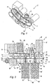
- a power take-off mechanism causing a drive shaft mechanically connected to an accessory relay box 1 hereinafter denoted by its acronym AGB 1 for "Accessory Gear Box".
- AGB 1 for "Accessory Gear Box”.
- the PTO shaft transmits the movement of the rotary shaft of the high pressure body to an input (or drive) shaft of the AGB 1.
- the input shaft of the AGB 1 is connected to the AGB 1 by a connecting piece 11 fixed to a wall of the AGB, in this case on the upper wall of the figure 1 .
- the input shaft, supported by the connecting piece 11, passes through the upper wall of the AGB 1 in a conventional manner.
- the turbojet also comprises a lubrication circuit comprising an oil reservoir 2, a lubricating group 9a (not shown in FIG. figure 1 but visible on the figure 2 ) and oil transport pipes to the bodies to be lubricated, not shown.
- the lubricating group 9a comprises in this case an oil supply pump of a main pipe from which the oil is guided to supply all the oil supply lines of the various components of the engine, these pipelines being directly or indirectly connected to the mainline.
- the lubricating group 9a further comprises a plurality of pumps - in this case four pumps - which suck up the recovered oil (usually by gravity) into the turbojet engines which have been lubricated; the oil thus recovered is reintroduced into the oil reservoir 2 from which it is drawn to supply the main pipe of the circuit.
- the lubrication system supplies lubricating oil to the components or equipment of the engine that require it, for example the shaft bearings of the motor or the gear of the AGB 1.
- This set E comprises a housing 4 formed by two half-shells 4a, 4b defining a first compartment 5a and a second compartment 5b, respectively, the two compartments 5a, 5b being separated by a partition 6.
- the first compartment 5a forms the AGB 1.
- it provides a housing for a gear 7 (or mechanism 7) mechanically connected to the input shaft of the AGB 1, the gear 7 being arranged to transmit the movements of the input shaft of the AGB 1 to the accessories 9a, 9b, 9c, 9d, 9e, 9f of the turbojet engine.
- the gear 7 comprises a plurality of toothed wheels 7a, 7b, 7c, 7d, 7d, 7e, 7f secured to a plurality of drive shafts 8a, 8b, 8c, 8d, 8e, 8f of the accessories 9a, 9b, 9c, 9d, 9e, 9f, respectively.
- a toothed wheel 7g in this case a conical pinion 7g integral with one of the shafts 8d, which meshes with a conical pinion integral with the input shaft of the AGB 1 for the drive of the set of wheels 7a-7f of the gear 7 by the input shaft of the AGB 1.
- Each drive shaft 8a, 8b, 8c, 8d, 8d, 8e, 8f extends along an axis 8 ', 8b', 8c ', 8d', 8d ', 8e', 8f.
- the shafts 8a-8f are arranged parallel to each other, conventionally in an AGB 1.
- the accessories comprise the lubrication group 9a, a fuel pump 9b, an air starter 9c, a low generator power 9d such as a permanent magnet motor, a starter-generator 9e and a hydraulic pump 9f; these accessories 9a-9f are given by way of example.
- the second compartment 5b serves as a reservoir for the oil of the lubrication circuit; in other words, it forms the oil reservoir 2 of this circuit. It forms a closed enclosure in which the oil rests.
- the separating partition wall 6 between the two compartments 5a, 5b is fixed between the two half-shells 4a, 4b forming the compartments 5a, 5b and prohibits any fluid communication between them, to prevent the oil from the tank 2 from coming into contact with each other. to flow unduly in the compartment 5a of the AGB 1.
- the partition 6 extends perpendicularly to the shafts 8a, 8b, 8c, 8d, 8e, 8f.
- the set E of the AGB 1 and the oil tank 2 is in this case of generally elongated shape. More specifically, the housing 4 of the assembly E generally has an elongated and curved shape, in this case adapted to follow the shape of a housing (cylindrical) of the turbojet engine on which it is intended to be fixed.
- banana or "bean”shape; it is more precisely a shape with faces (front and back on the figure 1 ), perpendicular to the shafts and drive 8a-8f, which are flat and parallel to each other; these faces (front and back) are connected by faces (lower and upper on the figure 1 ) each in the form of a cylinder portion; the ends of the housing 4 are formed by curved faces continuously connecting the cylindrical faces together.
- the large (average) dimension of the assembly E is perpendicular to the accessory drive shafts 8a-8f 9a-9f.
- Each half-naughty 4a, 4b has an opening on the entire face that is perpendicular to the drive shafts 8a-8f 9a-9f accessories.
- the opening of each half-shell 4a, 4b is delimited by an edge 10a, 10b here in the form of a flange 10a, 10b, respectively; thus, this flange 10a, 10b extends perpendicularly to the drive shafts 8a-8f.
- the half-shells 4a, 4b are attached to each other along these flanges 10a, 10b, in this case by screwing.
- the partition wall 6 is also fixed to the assembly E by screwing; in this case, the same screws allow the attachment of the flanges 10a, 10b to each other and to the periphery of the partition wall 6 which is sandwiched between the flanges 10a, 10b.
- the opening of the half-shells 4a, 4b forming the AGB 1 and the oil reservoir 2 have sufficient dimensions to allow the implementation of a machining process and in particular allow the passage of machining tools, for example milling tools.
- the openings here have dimensions corresponding to the projected image of the set of the gear 7 that the AGB 1 must contain on a plane perpendicular to the drive shafts 7, for example on an average plane of the plane. partition wall 8; this projected image or projection corresponds to the transverse size, with respect to the axes 8a'-8f 'of the drive shafts 8a-8f, the gear 7 of the AGB 1.
- the partition wall 6 is fixedly secured and not removable to the half-shell 4b forming the oil reservoir 2; such a fixing can for example be implemented by welding.
- the advantage of such a solution is the following. It can sometimes it is necessary to disassemble the assembly E of an AGB 1 and a tank 2 to carry out maintenance operations on the gear 7 of the AGB 1. Such operations are however not necessary on the fuel tank. 2.
- the partition 6 it is possible for the partition 6 to be fixedly secured to the oil reservoir 2 but fixed (with the oil reservoir 2) removably to the half-shell 4a forming the AGB 1 .
- some accessories 9a, 9c, 9e are mounted directly on the half-shell 4b forming the oil reservoir 2. More specifically, the lubrication group 9a is mounted, in part, directly in the volume of the oil tank 2 (in a protective jacket 12); thus, the pumps of the lubricating group 9a suck or pour oil directly into the tank 2.
- the air starter 9c and the starter-generator 9e are mounted on the wall of the half-shell 4b which faces the partition 6 and therefore extends perpendicular to their drive shafts 8a-8f (it is the front wall on the figure 1 ).
Landscapes
- Engineering & Computer Science (AREA)
- Chemical & Material Sciences (AREA)
- Combustion & Propulsion (AREA)
- Mechanical Engineering (AREA)
- General Engineering & Computer Science (AREA)
- General Details Of Gearings (AREA)
- Lubrication Of Internal Combustion Engines (AREA)
- Lubrication Details And Ventilation Of Internal Combustion Engines (AREA)
Applications Claiming Priority (2)
| Application Number | Priority Date | Filing Date | Title |
|---|---|---|---|
| FR0950617A FR2941744B1 (fr) | 2009-01-30 | 2009-01-30 | Ensemble d'un boitier de relais d'accessoires et d'un reservoir d'huile |
| PCT/EP2010/051122 WO2010086422A1 (fr) | 2009-01-30 | 2010-01-29 | Ensemble d'un agb et d'un reservoir d'huile |
Publications (2)
| Publication Number | Publication Date |
|---|---|
| EP2391803A1 EP2391803A1 (fr) | 2011-12-07 |
| EP2391803B1 true EP2391803B1 (fr) | 2016-07-27 |
Family
ID=41060236
Family Applications (1)
| Application Number | Title | Priority Date | Filing Date |
|---|---|---|---|
| EP10701690.9A Active EP2391803B1 (fr) | 2009-01-30 | 2010-01-29 | Ensemble d'un agb et d'un reservoir d'huile |
Country Status (11)
| Country | Link |
|---|---|
| US (1) | US8905191B2 (pl) |
| EP (1) | EP2391803B1 (pl) |
| JP (1) | JP5479495B2 (pl) |
| CN (1) | CN102301097B (pl) |
| BR (1) | BRPI1007421B1 (pl) |
| CA (1) | CA2750490C (pl) |
| ES (1) | ES2600517T3 (pl) |
| FR (1) | FR2941744B1 (pl) |
| PL (1) | PL2391803T3 (pl) |
| RU (1) | RU2538373C2 (pl) |
| WO (1) | WO2010086422A1 (pl) |
Cited By (1)
| Publication number | Priority date | Publication date | Assignee | Title |
|---|---|---|---|---|
| FR3162472A1 (fr) | 2024-05-23 | 2025-11-28 | Safran Transmission Systems | Ensemble comprenant un boitier, un circuit d’huile et un circuit de carburant |
Families Citing this family (39)
| Publication number | Priority date | Publication date | Assignee | Title |
|---|---|---|---|---|
| US9765861B2 (en) | 2011-04-07 | 2017-09-19 | Kawasaki Jukogyo Kabushiki Kaisha | Sealing arrangement of accessory to aircraft engine |
| US9926849B2 (en) * | 2011-06-14 | 2018-03-27 | Honeywell International Inc. | Transverse mounted accessory gearbox |
| FR2977280B1 (fr) * | 2011-06-28 | 2015-04-10 | Hispano Suiza Sa | Boitier perfectionne de relais d'accessoires d'une turbine a gaz |
| FR2981986B1 (fr) * | 2011-10-26 | 2016-03-04 | Snecma | Boitier d'entrainement d'accessoires pour turboreacteur |
| US9068515B2 (en) * | 2011-12-07 | 2015-06-30 | United Technologies Corporation | Accessory gearbox with tower shaft removal capability |
| FR2998498B1 (fr) * | 2012-11-27 | 2014-11-14 | Hispano Suiza Sa | Procede de realisation d'un carter de transmission de puissance |
| WO2014130239A2 (en) | 2013-02-25 | 2014-08-28 | United Technologies Corporation | Auxiliary lubricant supply pump stage integral with main lubricant pump stage |
| FR3007462B1 (fr) * | 2013-06-21 | 2017-11-24 | Hispano-Suiza | Boitier d'accessoires de turbomachine equipe d'une pompe centrifuge |
| FR3016407B1 (fr) | 2014-01-16 | 2016-02-19 | Hispano Suiza Sa | Boitier d'entrainement pour equipements |
| FR3016408B1 (fr) * | 2014-01-16 | 2019-05-31 | Safran Transmission Systems | Ensemble d'entrainement d'accessoires pour turbomachine d'aeronef |
| FR3017658B1 (fr) * | 2014-02-18 | 2019-04-12 | Safran Transmission Systems | Boitier d'entrainement d'equipements pour turbomachine |
| FR3021358B1 (fr) * | 2014-05-23 | 2018-07-20 | Safran Aircraft Engines | Boite d'engrenages de turbomachine d'aeronef |
| FR3027367B1 (fr) | 2014-10-17 | 2018-02-09 | Safran Transmission Systems | Support d'equipement d'une turbomachine comprenant un reducteur magnetique |
| FR3027346B1 (fr) * | 2014-10-20 | 2019-08-09 | Safran Helicopter Engines | Pack amovible de reactivation d'un turbomoteur, architecture d'un systeme propulsif d'un helicoptere multi-moteur equipe d'un tel pack et helicoptere correspondant |
| US9917490B2 (en) * | 2014-11-21 | 2018-03-13 | Hamilton Sundstrand Corporation | Tail cone generator with integral speed increasing gearbox |
| FR3041052B1 (fr) * | 2015-09-14 | 2018-07-27 | Safran Transmission Systems | Boitier d'entrainement d'equipements dans une turbomachine |
| US10072582B2 (en) * | 2016-04-28 | 2018-09-11 | General Electric Company | Integral offset oil tank for inline accessory gearbox |
| US11415063B2 (en) | 2016-09-15 | 2022-08-16 | Pratt & Whitney Canada Corp. | Reverse-flow gas turbine engine |
| US10883424B2 (en) | 2016-07-19 | 2021-01-05 | Pratt & Whitney Canada Corp. | Multi-spool gas turbine engine architecture |
| US10676205B2 (en) * | 2016-08-19 | 2020-06-09 | General Electric Company | Propulsion engine for an aircraft |
| US10465611B2 (en) | 2016-09-15 | 2019-11-05 | Pratt & Whitney Canada Corp. | Reverse flow multi-spool gas turbine engine with aft-end accessory gearbox drivingly connected to both high pressure spool and low pressure spool |
| US11035293B2 (en) | 2016-09-15 | 2021-06-15 | Pratt & Whitney Canada Corp. | Reverse flow gas turbine engine with offset RGB |
| US10815899B2 (en) | 2016-11-15 | 2020-10-27 | Pratt & Whitney Canada Corp. | Gas turbine engine accessories arrangement |
| FR3059361B1 (fr) * | 2016-11-28 | 2018-12-07 | Safran Aircraft Engines | Reservoir d'huile comprenant un dispositif de controle du niveau d'huile |
| US10808624B2 (en) | 2017-02-09 | 2020-10-20 | Pratt & Whitney Canada Corp. | Turbine rotor with low over-speed requirements |
| US10746188B2 (en) | 2017-03-14 | 2020-08-18 | Pratt & Whitney Canada Corp. | Inter-shaft bearing connected to a compressor boost system |
| FR3070726B1 (fr) * | 2017-09-07 | 2019-08-23 | Safran Transmission Systems | Boitier d'accessoires pour turbomachine |
| RU186180U1 (ru) * | 2018-06-06 | 2019-01-11 | Публичное акционерное общество "МОТОР СИЧ" | Узел соединения входного устройства и коробки приводов турбовинтового двигателя |
| GB201811219D0 (en) * | 2018-07-09 | 2018-08-29 | Rolls Royce Plc | Apparatus for gas turbine engines |
| EP3653859B1 (en) | 2018-08-08 | 2024-02-07 | Pratt & Whitney Canada Corp. | Multi-engine system and method |
| FR3086974B1 (fr) | 2018-10-04 | 2021-01-08 | Safran Trans Systems | Boitier d'engrenages de turbomachine |
| US11008945B2 (en) | 2018-10-18 | 2021-05-18 | Rolls-Royce North American Technologies, Inc. | Accessory gearbox with oppositely disposed starter/generator and air turbine starter |
| US11261795B2 (en) | 2018-10-18 | 2022-03-01 | Rolls-Royce North American Technologies, Inc. | Dual mode starter generator |
| CA3053117A1 (en) * | 2018-10-18 | 2020-04-18 | Rolls-Royce North American Technologies Inc. | Dual mode starter generator |
| FR3095832B1 (fr) * | 2019-05-10 | 2021-05-21 | Safran Aircraft Engines | Système huile pour turbomachine |
| FR3104640B1 (fr) * | 2019-12-13 | 2021-12-10 | Safran Aircraft Engines | Platine d’équipements hydrauliques de turbomachine aéronautique |
| FR3106155B1 (fr) | 2020-01-09 | 2022-07-15 | Safran Aircraft Engines | Système de lubrification d’engrenages pour une turbomachine d’aéronef |
| US11572838B2 (en) * | 2020-09-29 | 2023-02-07 | General Electric Company | Accessory gearbox for a turbine engine |
| FR3139864B1 (fr) * | 2022-09-20 | 2024-10-18 | Safran Trans Systems | Boitier d’accessoires compact comportant une machine electrique integree |
Family Cites Families (24)
| Publication number | Priority date | Publication date | Assignee | Title |
|---|---|---|---|---|
| US2432358A (en) * | 1944-03-07 | 1947-12-09 | Gen Electric | Power plant |
| US2548858A (en) * | 1949-06-24 | 1951-04-17 | Westinghouse Electric Corp | Gas turbine apparatus |
| US2702093A (en) * | 1949-10-21 | 1955-02-15 | Bendix Aviat Corp | Lubricating system for high-speed machines |
| US2618119A (en) * | 1949-12-19 | 1952-11-18 | Westinghouse Electric Corp | Turbine apparatus |
| US2803943A (en) * | 1953-12-30 | 1957-08-27 | Armstrong Siddeley Motors Ltd | Means for supporting and driving accessories which are exterior to a ductedfan turbo-jet engine |
| GB758206A (en) * | 1953-12-30 | 1956-10-03 | Armstrong Siddeley Motors Ltd | Improvements relating to by-pass turbo-jet engines |
| US2978869A (en) * | 1956-11-01 | 1961-04-11 | Bristol Siddeley Engines Ltd | Engine accessory mounting arrangements |
| US3152443A (en) * | 1959-07-17 | 1964-10-13 | United Aircraft Canada | Gas turbine powerplant |
| US3135353A (en) * | 1960-09-29 | 1964-06-02 | Specialties Dev Corp | Lubricating and cooling system |
| US3499503A (en) * | 1967-03-31 | 1970-03-10 | Carrier Corp | Lubrication system |
| JPS52129805U (pl) * | 1976-03-31 | 1977-10-03 | ||
| US4068740A (en) * | 1976-06-23 | 1978-01-17 | Philadelphia Gear Corporation | Gear pump assembly |
| US4525995A (en) * | 1983-04-04 | 1985-07-02 | Williams International Corporation | Oil scavening system for gas turbine engine |
| FR2607185B1 (fr) * | 1986-11-20 | 1990-05-04 | Snecma | Systeme de lubrification pour demarreur de turbomachine |
| EP0540192A1 (en) * | 1991-10-30 | 1993-05-05 | General Electric Company | Accessory drive assembly |
| RU2162158C1 (ru) * | 1999-12-24 | 2001-01-20 | ГОСУДАРСТВЕННОЕ УНИТАРНОЕ ПРЕДПРИЯТИЕ ТУШИНСКОЕ МАШИНОСТРОИТЕЛЬНОЕ КОНСТРУКТОРСКОЕ БЮРО "СОЮЗ" Военно-промышленный комплекс "МАПО" | Коробка приводов вспомогательных агрегатов авиационного газотурбинного двигателя |
| US6814537B2 (en) | 2001-09-26 | 2004-11-09 | Ingersoll-Rand Energy Systems Corporation | Interchangeable power turbine cartridge assembly |
| US7063734B2 (en) * | 2004-03-23 | 2006-06-20 | Pratt & Whitney Canada Corp. | Air/oil separation system and method |
| US7204090B2 (en) * | 2004-06-17 | 2007-04-17 | Pratt & Whitney Canada Corp. | Modulated current gas turbine engine starting system |
| US7805947B2 (en) * | 2005-05-19 | 2010-10-05 | Djamal Moulebhar | Aircraft with disengageable engine and auxiliary power unit components |
| BRPI0621383B1 (pt) * | 2006-02-27 | 2019-12-03 | Hispano Suiza Sa | conjunto que compreende uma caixa de transmissão de turbina a gás e pelo menos um motor de arranque/gerador, turbina a gás, motor aeronáutico, grupo auxiliar de potência com turbina a gás, e, módulo de motor de arranque/gerador |
| FR2911916B1 (fr) * | 2007-01-30 | 2009-03-27 | Hispano Suiza Sa | Moteur a turbine a gaz incorporant un demarreur monte sur la boite a engrenages |
| US8312728B2 (en) * | 2007-06-28 | 2012-11-20 | United Technologies Corporation | Generator with separate oil system for improved nacelle performance |
| US8210800B2 (en) * | 2008-06-12 | 2012-07-03 | United Technologies Corporation | Integrated actuator module for gas turbine engine |
-
2009
- 2009-01-30 FR FR0950617A patent/FR2941744B1/fr active Active
-
2010
- 2010-01-29 RU RU2011135971/06A patent/RU2538373C2/ru active
- 2010-01-29 CN CN201080005718.XA patent/CN102301097B/zh active Active
- 2010-01-29 CA CA2750490A patent/CA2750490C/fr not_active Expired - Fee Related
- 2010-01-29 JP JP2011546860A patent/JP5479495B2/ja not_active Expired - Fee Related
- 2010-01-29 PL PL10701690T patent/PL2391803T3/pl unknown
- 2010-01-29 BR BRPI1007421-0A patent/BRPI1007421B1/pt not_active IP Right Cessation
- 2010-01-29 EP EP10701690.9A patent/EP2391803B1/fr active Active
- 2010-01-29 ES ES10701690.9T patent/ES2600517T3/es active Active
- 2010-01-29 US US13/146,944 patent/US8905191B2/en active Active
- 2010-01-29 WO PCT/EP2010/051122 patent/WO2010086422A1/fr not_active Ceased
Cited By (1)
| Publication number | Priority date | Publication date | Assignee | Title |
|---|---|---|---|---|
| FR3162472A1 (fr) | 2024-05-23 | 2025-11-28 | Safran Transmission Systems | Ensemble comprenant un boitier, un circuit d’huile et un circuit de carburant |
Also Published As
| Publication number | Publication date |
|---|---|
| FR2941744A1 (fr) | 2010-08-06 |
| US20110284328A1 (en) | 2011-11-24 |
| ES2600517T3 (es) | 2017-02-09 |
| PL2391803T3 (pl) | 2017-01-31 |
| CN102301097B (zh) | 2015-07-01 |
| RU2011135971A (ru) | 2013-03-10 |
| CA2750490C (fr) | 2016-11-08 |
| WO2010086422A1 (fr) | 2010-08-05 |
| BRPI1007421A2 (pt) | 2016-02-16 |
| EP2391803A1 (fr) | 2011-12-07 |
| FR2941744B1 (fr) | 2011-09-16 |
| JP5479495B2 (ja) | 2014-04-23 |
| US8905191B2 (en) | 2014-12-09 |
| CA2750490A1 (fr) | 2010-08-05 |
| JP2012516407A (ja) | 2012-07-19 |
| BRPI1007421B1 (pt) | 2020-10-27 |
| CN102301097A (zh) | 2011-12-28 |
| RU2538373C2 (ru) | 2015-01-10 |
Similar Documents
| Publication | Publication Date | Title |
|---|---|---|
| EP2391803B1 (fr) | Ensemble d'un agb et d'un reservoir d'huile | |
| CA2536129C (fr) | Turbomoteur a double corps avec des moyens de prise de mouvement sur les rotors basse pression et haute pression, module de prise de mouvement pour le turbomoteur et procede de montage du turbomoteur | |
| EP1911938B1 (fr) | Turboréacteur | |
| EP3071792B1 (fr) | Moteur modulaire | |
| CA2951196C (fr) | Turbomachine comprenant un systeme d'entrainement d'un equipement tel qu'un boitier d'accessoires | |
| EP3137740B1 (fr) | Assemblage pour turbomachine d'aeronef et son procede de montage | |
| EP4652362A1 (fr) | Ensemble comprenant une boite d'entrainement d'accessoires et un groupe de lubrification | |
| FR3017660A1 (fr) | Ensemble d'entrainement de machines auxiliaires destine a entrainer des machines auxiliaires dans un turboreacteur d'aeronef | |
| EP3862551B1 (fr) | Boîtier de relais d'accessoires pour une turbomachine | |
| EP4267839A1 (fr) | Module de turbomachine equipe d'une machine electrique et turbomachine equipee d'un tel module | |
| EP4158173A1 (fr) | Turbomachine equipee de machines electriques accouplees a une surface d'accouplement | |
| WO2021240094A1 (fr) | Turbomachine equipee de deux machines electriques montees en serie avec un reducteur de vitesse | |
| FR3162472A1 (fr) | Ensemble comprenant un boitier, un circuit d’huile et un circuit de carburant | |
| FR3110932A1 (fr) | Turbomachine equipee de machines electriques | |
| FR3110933A1 (fr) | Turbomachine equipee de machines electriques | |
| FR3110930A1 (fr) | Turbomachine equipee d’une machine electrique avec un stator dans un bras structural | |
| FR3055308A1 (fr) | Moyen de commande d'un systeme de changement de pas comprenant un dispositif anti-rotation, systeme de changement de pas equipe dudit moyen de commande et turbomachine correspondante |
Legal Events
| Date | Code | Title | Description |
|---|---|---|---|
| PUAI | Public reference made under article 153(3) epc to a published international application that has entered the european phase |
Free format text: ORIGINAL CODE: 0009012 |
|
| 17P | Request for examination filed |
Effective date: 20110826 |
|
| AK | Designated contracting states |
Kind code of ref document: A1 Designated state(s): AT BE BG CH CY CZ DE DK EE ES FI FR GB GR HR HU IE IS IT LI LT LU LV MC MK MT NL NO PL PT RO SE SI SK SM TR |
|
| RIN1 | Information on inventor provided before grant (corrected) |
Inventor name: BRANDT, BERNARD Inventor name: DEPERROIS, ANDRE, RAYMOND, CHRISTIAN Inventor name: COTIN, FREDERIC |
|
| DAX | Request for extension of the european patent (deleted) | ||
| 17Q | First examination report despatched |
Effective date: 20150713 |
|
| GRAP | Despatch of communication of intention to grant a patent |
Free format text: ORIGINAL CODE: EPIDOSNIGR1 |
|
| INTG | Intention to grant announced |
Effective date: 20160302 |
|
| GRAS | Grant fee paid |
Free format text: ORIGINAL CODE: EPIDOSNIGR3 |
|
| GRAA | (expected) grant |
Free format text: ORIGINAL CODE: 0009210 |
|
| AK | Designated contracting states |
Kind code of ref document: B1 Designated state(s): AT BE BG CH CY CZ DE DK EE ES FI FR GB GR HR HU IE IS IT LI LT LU LV MC MK MT NL NO PL PT RO SE SI SK SM TR |
|
| REG | Reference to a national code |
Ref country code: GB Ref legal event code: FG4D Free format text: NOT ENGLISH |
|
| REG | Reference to a national code |
Ref country code: CH Ref legal event code: EP |
|
| REG | Reference to a national code |
Ref country code: AT Ref legal event code: REF Ref document number: 815981 Country of ref document: AT Kind code of ref document: T Effective date: 20160815 |
|
| REG | Reference to a national code |
Ref country code: IE Ref legal event code: FG4D Free format text: LANGUAGE OF EP DOCUMENT: FRENCH |
|
| REG | Reference to a national code |
Ref country code: DE Ref legal event code: R096 Ref document number: 602010035015 Country of ref document: DE |
|
| RAP2 | Party data changed (patent owner data changed or rights of a patent transferred) |
Owner name: SAFRAN TRANSMISSION SYSTEMS |
|
| REG | Reference to a national code |
Ref country code: LT Ref legal event code: MG4D |
|
| REG | Reference to a national code |
Ref country code: NL Ref legal event code: MP Effective date: 20160727 |
|
| REG | Reference to a national code |
Ref country code: AT Ref legal event code: MK05 Ref document number: 815981 Country of ref document: AT Kind code of ref document: T Effective date: 20160727 |
|
| REG | Reference to a national code |
Ref country code: FR Ref legal event code: PLFP Year of fee payment: 8 |
|
| PG25 | Lapsed in a contracting state [announced via postgrant information from national office to epo] |
Ref country code: LT Free format text: LAPSE BECAUSE OF FAILURE TO SUBMIT A TRANSLATION OF THE DESCRIPTION OR TO PAY THE FEE WITHIN THE PRESCRIBED TIME-LIMIT Effective date: 20160727 Ref country code: HR Free format text: LAPSE BECAUSE OF FAILURE TO SUBMIT A TRANSLATION OF THE DESCRIPTION OR TO PAY THE FEE WITHIN THE PRESCRIBED TIME-LIMIT Effective date: 20160727 Ref country code: FI Free format text: LAPSE BECAUSE OF FAILURE TO SUBMIT A TRANSLATION OF THE DESCRIPTION OR TO PAY THE FEE WITHIN THE PRESCRIBED TIME-LIMIT Effective date: 20160727 Ref country code: IS Free format text: LAPSE BECAUSE OF FAILURE TO SUBMIT A TRANSLATION OF THE DESCRIPTION OR TO PAY THE FEE WITHIN THE PRESCRIBED TIME-LIMIT Effective date: 20161127 Ref country code: NO Free format text: LAPSE BECAUSE OF FAILURE TO SUBMIT A TRANSLATION OF THE DESCRIPTION OR TO PAY THE FEE WITHIN THE PRESCRIBED TIME-LIMIT Effective date: 20161027 Ref country code: NL Free format text: LAPSE BECAUSE OF FAILURE TO SUBMIT A TRANSLATION OF THE DESCRIPTION OR TO PAY THE FEE WITHIN THE PRESCRIBED TIME-LIMIT Effective date: 20160727 |
|
| REG | Reference to a national code |
Ref country code: ES Ref legal event code: FG2A Ref document number: 2600517 Country of ref document: ES Kind code of ref document: T3 Effective date: 20170209 |
|
| PG25 | Lapsed in a contracting state [announced via postgrant information from national office to epo] |
Ref country code: LV Free format text: LAPSE BECAUSE OF FAILURE TO SUBMIT A TRANSLATION OF THE DESCRIPTION OR TO PAY THE FEE WITHIN THE PRESCRIBED TIME-LIMIT Effective date: 20160727 Ref country code: SE Free format text: LAPSE BECAUSE OF FAILURE TO SUBMIT A TRANSLATION OF THE DESCRIPTION OR TO PAY THE FEE WITHIN THE PRESCRIBED TIME-LIMIT Effective date: 20160727 Ref country code: PT Free format text: LAPSE BECAUSE OF FAILURE TO SUBMIT A TRANSLATION OF THE DESCRIPTION OR TO PAY THE FEE WITHIN THE PRESCRIBED TIME-LIMIT Effective date: 20161128 Ref country code: GR Free format text: LAPSE BECAUSE OF FAILURE TO SUBMIT A TRANSLATION OF THE DESCRIPTION OR TO PAY THE FEE WITHIN THE PRESCRIBED TIME-LIMIT Effective date: 20161028 Ref country code: AT Free format text: LAPSE BECAUSE OF FAILURE TO SUBMIT A TRANSLATION OF THE DESCRIPTION OR TO PAY THE FEE WITHIN THE PRESCRIBED TIME-LIMIT Effective date: 20160727 |
|
| PG25 | Lapsed in a contracting state [announced via postgrant information from national office to epo] |
Ref country code: RO Free format text: LAPSE BECAUSE OF FAILURE TO SUBMIT A TRANSLATION OF THE DESCRIPTION OR TO PAY THE FEE WITHIN THE PRESCRIBED TIME-LIMIT Effective date: 20160727 Ref country code: EE Free format text: LAPSE BECAUSE OF FAILURE TO SUBMIT A TRANSLATION OF THE DESCRIPTION OR TO PAY THE FEE WITHIN THE PRESCRIBED TIME-LIMIT Effective date: 20160727 |
|
| REG | Reference to a national code |
Ref country code: DE Ref legal event code: R097 Ref document number: 602010035015 Country of ref document: DE |
|
| PG25 | Lapsed in a contracting state [announced via postgrant information from national office to epo] |
Ref country code: BE Free format text: LAPSE BECAUSE OF NON-PAYMENT OF DUE FEES Effective date: 20170131 Ref country code: BG Free format text: LAPSE BECAUSE OF FAILURE TO SUBMIT A TRANSLATION OF THE DESCRIPTION OR TO PAY THE FEE WITHIN THE PRESCRIBED TIME-LIMIT Effective date: 20161027 Ref country code: DK Free format text: LAPSE BECAUSE OF FAILURE TO SUBMIT A TRANSLATION OF THE DESCRIPTION OR TO PAY THE FEE WITHIN THE PRESCRIBED TIME-LIMIT Effective date: 20160727 Ref country code: SK Free format text: LAPSE BECAUSE OF FAILURE TO SUBMIT A TRANSLATION OF THE DESCRIPTION OR TO PAY THE FEE WITHIN THE PRESCRIBED TIME-LIMIT Effective date: 20160727 Ref country code: CZ Free format text: LAPSE BECAUSE OF FAILURE TO SUBMIT A TRANSLATION OF THE DESCRIPTION OR TO PAY THE FEE WITHIN THE PRESCRIBED TIME-LIMIT Effective date: 20160727 Ref country code: SM Free format text: LAPSE BECAUSE OF FAILURE TO SUBMIT A TRANSLATION OF THE DESCRIPTION OR TO PAY THE FEE WITHIN THE PRESCRIBED TIME-LIMIT Effective date: 20160727 |
|
| PLBE | No opposition filed within time limit |
Free format text: ORIGINAL CODE: 0009261 |
|
| STAA | Information on the status of an ep patent application or granted ep patent |
Free format text: STATUS: NO OPPOSITION FILED WITHIN TIME LIMIT |
|
| 26N | No opposition filed |
Effective date: 20170502 |
|
| PG25 | Lapsed in a contracting state [announced via postgrant information from national office to epo] |
Ref country code: SI Free format text: LAPSE BECAUSE OF FAILURE TO SUBMIT A TRANSLATION OF THE DESCRIPTION OR TO PAY THE FEE WITHIN THE PRESCRIBED TIME-LIMIT Effective date: 20160727 |
|
| REG | Reference to a national code |
Ref country code: CH Ref legal event code: PL |
|
| PG25 | Lapsed in a contracting state [announced via postgrant information from national office to epo] |
Ref country code: MC Free format text: LAPSE BECAUSE OF FAILURE TO SUBMIT A TRANSLATION OF THE DESCRIPTION OR TO PAY THE FEE WITHIN THE PRESCRIBED TIME-LIMIT Effective date: 20160727 |
|
| PG25 | Lapsed in a contracting state [announced via postgrant information from national office to epo] |
Ref country code: CH Free format text: LAPSE BECAUSE OF NON-PAYMENT OF DUE FEES Effective date: 20170131 Ref country code: LI Free format text: LAPSE BECAUSE OF NON-PAYMENT OF DUE FEES Effective date: 20170131 |
|
| REG | Reference to a national code |
Ref country code: IE Ref legal event code: MM4A |
|
| PG25 | Lapsed in a contracting state [announced via postgrant information from national office to epo] |
Ref country code: LU Free format text: LAPSE BECAUSE OF NON-PAYMENT OF DUE FEES Effective date: 20170129 |
|
| REG | Reference to a national code |
Ref country code: FR Ref legal event code: PLFP Year of fee payment: 9 |
|
| REG | Reference to a national code |
Ref country code: BE Ref legal event code: MM Effective date: 20170131 |
|
| PG25 | Lapsed in a contracting state [announced via postgrant information from national office to epo] |
Ref country code: IE Free format text: LAPSE BECAUSE OF NON-PAYMENT OF DUE FEES Effective date: 20170129 |
|
| PG25 | Lapsed in a contracting state [announced via postgrant information from national office to epo] |
Ref country code: MT Free format text: LAPSE BECAUSE OF FAILURE TO SUBMIT A TRANSLATION OF THE DESCRIPTION OR TO PAY THE FEE WITHIN THE PRESCRIBED TIME-LIMIT Effective date: 20160727 |
|
| PGFP | Annual fee paid to national office [announced via postgrant information from national office to epo] |
Ref country code: PL Payment date: 20181219 Year of fee payment: 10 |
|
| PGFP | Annual fee paid to national office [announced via postgrant information from national office to epo] |
Ref country code: IS Payment date: 20190109 Year of fee payment: 10 |
|
| PG25 | Lapsed in a contracting state [announced via postgrant information from national office to epo] |
Ref country code: HU Free format text: LAPSE BECAUSE OF FAILURE TO SUBMIT A TRANSLATION OF THE DESCRIPTION OR TO PAY THE FEE WITHIN THE PRESCRIBED TIME-LIMIT; INVALID AB INITIO Effective date: 20100129 |
|
| PG25 | Lapsed in a contracting state [announced via postgrant information from national office to epo] |
Ref country code: CY Free format text: LAPSE BECAUSE OF NON-PAYMENT OF DUE FEES Effective date: 20160727 |
|
| PG25 | Lapsed in a contracting state [announced via postgrant information from national office to epo] |
Ref country code: MK Free format text: LAPSE BECAUSE OF FAILURE TO SUBMIT A TRANSLATION OF THE DESCRIPTION OR TO PAY THE FEE WITHIN THE PRESCRIBED TIME-LIMIT Effective date: 20160727 |
|
| PG25 | Lapsed in a contracting state [announced via postgrant information from national office to epo] |
Ref country code: TR Free format text: LAPSE BECAUSE OF FAILURE TO SUBMIT A TRANSLATION OF THE DESCRIPTION OR TO PAY THE FEE WITHIN THE PRESCRIBED TIME-LIMIT Effective date: 20160727 |
|
| PGFP | Annual fee paid to national office [announced via postgrant information from national office to epo] |
Ref country code: IT Payment date: 20210104 Year of fee payment: 12 |
|
| REG | Reference to a national code |
Ref country code: ES Ref legal event code: FD2A Effective date: 20210607 |
|
| PG25 | Lapsed in a contracting state [announced via postgrant information from national office to epo] |
Ref country code: ES Free format text: LAPSE BECAUSE OF NON-PAYMENT OF DUE FEES Effective date: 20200130 |
|
| PG25 | Lapsed in a contracting state [announced via postgrant information from national office to epo] |
Ref country code: PL Free format text: LAPSE BECAUSE OF NON-PAYMENT OF DUE FEES Effective date: 20200129 |
|
| PG25 | Lapsed in a contracting state [announced via postgrant information from national office to epo] |
Ref country code: IT Free format text: LAPSE BECAUSE OF NON-PAYMENT OF DUE FEES Effective date: 20220129 |
|
| PGFP | Annual fee paid to national office [announced via postgrant information from national office to epo] |
Ref country code: GB Payment date: 20241219 Year of fee payment: 16 |
|
| PGFP | Annual fee paid to national office [announced via postgrant information from national office to epo] |
Ref country code: FR Payment date: 20241219 Year of fee payment: 16 |
|
| PGFP | Annual fee paid to national office [announced via postgrant information from national office to epo] |
Ref country code: DE Payment date: 20241218 Year of fee payment: 16 |