EP2390975A2 - Kühlvorrichtung für eine elektrische Schaltanlage - Google Patents
Kühlvorrichtung für eine elektrische Schaltanlage Download PDFInfo
- Publication number
- EP2390975A2 EP2390975A2 EP11166868A EP11166868A EP2390975A2 EP 2390975 A2 EP2390975 A2 EP 2390975A2 EP 11166868 A EP11166868 A EP 11166868A EP 11166868 A EP11166868 A EP 11166868A EP 2390975 A2 EP2390975 A2 EP 2390975A2
- Authority
- EP
- European Patent Office
- Prior art keywords
- heat
- cooling device
- frame
- cooling
- plates
- Prior art date
- Legal status (The legal status is an assumption and is not a legal conclusion. Google has not performed a legal analysis and makes no representation as to the accuracy of the status listed.)
- Granted
Links
Images

Classifications
-
- H—ELECTRICITY
- H01—ELECTRIC ELEMENTS
- H01H—ELECTRIC SWITCHES; RELAYS; SELECTORS; EMERGENCY PROTECTIVE DEVICES
- H01H9/00—Details of switching devices, not covered by groups H01H1/00 - H01H7/00
- H01H9/52—Cooling of switch parts
-
- H—ELECTRICITY
- H01—ELECTRIC ELEMENTS
- H01H—ELECTRIC SWITCHES; RELAYS; SELECTORS; EMERGENCY PROTECTIVE DEVICES
- H01H1/00—Contacts
- H01H1/62—Heating or cooling of contacts
-
- H—ELECTRICITY
- H01—ELECTRIC ELEMENTS
- H01H—ELECTRIC SWITCHES; RELAYS; SELECTORS; EMERGENCY PROTECTIVE DEVICES
- H01H9/00—Details of switching devices, not covered by groups H01H1/00 - H01H7/00
- H01H9/52—Cooling of switch parts
- H01H2009/523—Cooling of switch parts by using heat pipes
-
- H—ELECTRICITY
- H01—ELECTRIC ELEMENTS
- H01H—ELECTRIC SWITCHES; RELAYS; SELECTORS; EMERGENCY PROTECTIVE DEVICES
- H01H9/00—Details of switching devices, not covered by groups H01H1/00 - H01H7/00
- H01H9/52—Cooling of switch parts
- H01H2009/526—Cooling of switch parts of the high voltage switches
-
- H—ELECTRICITY
- H02—GENERATION; CONVERSION OR DISTRIBUTION OF ELECTRIC POWER
- H02B—BOARDS, SUBSTATIONS OR SWITCHING ARRANGEMENTS FOR THE SUPPLY OR DISTRIBUTION OF ELECTRIC POWER
- H02B11/00—Switchgear having carriage withdrawable for isolation
- H02B11/02—Details
- H02B11/04—Isolating-contacts, e.g. mountings or shieldings
Definitions
- the invention relates to a cooling device for an electrical switchgear, in particular in the field of medium or high voltage engineering.
- a vacuum circuit breaker is known in which a contact piece is provided within the vacuum switch with a heat pipe. With the help of the heat pipe so the heat generated at the contact piece is guided out of the vacuum switch.
- a heat pipe In a heat pipe is a working fluid in an evacuated, hermetically sealed metal tube.
- the working medium evaporates and transports the heat to the cold end of the heat pipe.
- the working fluid condenses and releases the heat to the heat pipe and its surroundings.
- the condensed working fluid then flows back to the hot end of the heat pipe, for example, by means of gravitational force or capillary action in the heat pipe.
- the object of the invention is to improve the known cooling device.
- the invention solves this problem by a cooling device for an electrical switchgear, which is provided with a frame which limits a region in which a plurality of cooling plates are arranged, and which is further provided with at least one heat pipe, on the one hand with a heat-emitting portion the cooling device and on the other hand coupled to the cooling plates.
- the heat is thus transported from the heat-emitting portion of the hot end of the heat pipe to its cold end and thus to the cooling plates and discharged through this to the environment.
- the heat-emitting portion may be connected to a heat-emitting component of the switchgear, such as an electrical pole or an electrical conductor.
- the cooling device according to the invention can dissipate a high amount of heat and at the same time has a very compact and lightweight construction.
- the reduction to the frame, the cooling plates and the heat pipe also creates a very simple design and thus easy and inexpensive to produce cooling device.
- the arrangement of the cooling plates within the limited area of the frame has the advantage that the cooling plates are electrically shielded by means of the frame and also mechanically protected.
- the inventive Cooling device thus has a high dielectric strength even when used in the field of medium and high voltage technology.
- the heat pipe according to the invention is not used for dissipating heat, for example from a contact piece of a vacuum switch, but for dissipating the heat of a generally heat-emitting component of the switchgear to the cooling plates, from which the heat is then released to the environment.
- the portion of the cooling device is connected to at least one plate of a circuit breaker. This makes it possible in a simple manner, dissipate the heat usually generated at a circuit breaker via the cooling device according to the invention.
- a further, particularly advantageous embodiment of the invention is that the frame, the sub-area, the cooling plates, the heat pipe and the heat-emitting component of the switchgear are formed as an integrated component. This leads to a particularly compact design for the cooling device according to the invention.
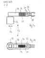
- FIGS. 1a, 1b show a schematic perspective view and a plan view of a first embodiment of a cooling device according to the invention
- FIGS. 2a, 2b show a schematic side and top view of a second embodiment of a cooling device according to the invention.
- FIGS. 1a, 1b a cooling device 10 is shown, which can be used for use in air or gas-insulated electrical switchgear of medium or high voltage engineering.
- FIGS. 1a, 1b for example, a pole 13 of a circuit breaker.
- This pole 13 has, by way of example, two disk-like plates 14, which are arranged at a distance and approximately parallel to one another.
- the other pole of the circuit breaker is in the FIG. 1 not shown.
- This other pole may, for example, be a swiveling switch blade which can either be pivoted between the two plates 14 or separated from the two plates 14.
- FIGS. 1a, 1b is shown the disconnected state in which the circuit breaker is thus in its current interrupting state.
- the circuit breaker may be connected to a pole of a vacuum switch.
- This vacuum switch can in a manner not shown for Example be arranged below the cooling device 10, ie in the perspective view of FIG. 1b in particular, approximately below the holes 16 of the cooling device 10 which are still to be explained.
- the two plates 14 of the circuit breaker are connected to each other by means of a plate-like portion 15 of the cooling device 10.
- the portion 15 starts from the distance between the two plates 14 and expands from there in the direction of the still to be explained frame 18 to a greater distance.
- the portion 15 has a plurality of holes 16 through which the circuit breaker 13 may be attached in any manner not shown in detail, for example, to the vacuum switch.
- the portion 15 is a current-carrying conductor element in the current path from the vacuum switch to the circuit breaker.
- the plates 14 and the portion 15 are integrally formed in an exemplary manner and are made of an electrically and thermally conductive material. It is understood that this arrangement can also be designed in several parts.
- the free ends of the two legs of the frame 18 are approximately in the same plane as the plates 14 of the portion 15 from.
- the frame 18 is made of an electrically conductive material and is exemplified integrally formed with the portion 15 and the plates 14. In that regard, it is in the embodiment of the FIGS. 1a, 1b around an integrated component. Alternatively it is possible that the frame 18, the portion 15 and the plates 14 are formed in several parts and each consist of an electrically conductive material.
- the cooling plates 19 are made of an electrically and thermally conductive material. Furthermore, the cooling plates 19 all have the same surface shape, are arranged at a distance and approximately parallel to each other and approximately planar.
- the cooling plates 19 are aligned approximately parallel to the connecting web of the U-shaped frame 18. If one assigns a length to this connecting web, the surface shape of the cooling plates 19 has approximately the same length. Assigning the frame 18 to a width extending approximately transversely to the direction of the connecting web, the surface shape of the cooling plates 19 has approximately the same width.
- cooling plates 19 may also be designed differently. It is also possible that the cooling plates 19 are not flat, but have a shape, for example, provided with bulges or openings. Finally, it is also possible that the cooling plates 19 are replaced by a plurality of cooling pins, for example, projecting from a flat base part, which is located within the area enclosed by the U-shaped frame 18 area.
- the frame 18 is used for electrical shielding of the cooling plates 19.
- the frame 18 thus avoids that small radii or other edges of the cooling plates 19 lead to electrical discharges.
- the frame 18 is a protection of the cooling plates 19 against mechanical damage.
- cooling plates 19 In the cooling plates 19 are openings through which two heat pipes 21 are inserted through the present embodiment.
- the heat pipes 21 are connected to the cooling plates 19, for example, soldered or pressed or expanded, that the best possible thermal transition is present.
- the heat pipes 21 are straight and extend approximately transversely to the orientation of the cooling plates 19th
- openings are also included, in which the two heat pipes 21 are inserted into and soldered, for example.
- the heat pipes 21 and the associated openings in the subregion 15 are adapted to one another in such a way that a form or interference fit and thus the best possible thermal transition is present.
- the heat pipes 21 are thus connected on one side to the portion 15, but otherwise have no connection to the frame 18.
- the portion 15 is formed in two parts, that the heat pipes 21 placed in between and then can be pressed by screwing.
- the two heat pipes 21 have a spacing and are aligned approximately parallel to one another. It is understood that even just one heat pipe 21 or more than two Heat pipes 21 may be present.
- the heat pipes 21 are made of an electrically conductive material.
- the heat pipes 21 are each a so-called "heat pipe".
- a working medium such as water
- Each of the heat pipes 21 has a heat transfer surface for a heat source and a heat transfer surface for a heat sink. If heating by the heat source takes place in the heat transfer surface for the heat source, the working medium begins to evaporate. As a result, the pressure in the heat pipe 21 is increased, which leads to a pressure gradient within the heat pipe 21. The resulting vapor thus flows in the direction of the heat transfer surface for the heat sink, where it condenses because of the lower temperature there.
- the heat previously emitted by the heat source and absorbed by the working medium is released to the heat transfer surface for the heat sink and thus to the heat pipe 21.
- the now liquid working medium returns by capillary action or capillary action of the respective heat pipe 21 back to the heat transfer surface for the heat source.
- the portion 15, the heat source and the cooling plates 19, the heat sink Furthermore, put in the portion 15 free ends of the heat pipes 21, the heat transfer surfaces for the heat source and through the cooling plates 19 inserted through the free ends of the heat pipes 21, the heat transfer surfaces for the heat sink.
- the pole 13 of the circuit breaker and the pole of the vacuum switch each represent a so-called hot spot.
- these two components are connected to one another via the partial region 15.
- the portion 15 forms a heat-emitting component.
- Heat that forms during operation of the switchgear for example, in the region of the two plates 14 of the circuit breaker, will thus deliver over the portion 15 to the heat-receiving end of the two heat pipes 21.
- the heat with the aid of the working medium in the direction of the other, heat-emitting end of the two heat pipes 21 is transported. There, the heat is released to the cooling plates 19.
- the heat is distributed on the surfaces of the cooling plates 19 and is discharged from there to the environment.
- the condensed working medium returns to the part 15 associated free ends of the heat pipes 21 back.
- the cooling device 10 is in the embodiment of the FIGS. 1a, 1b in particular from the plates 14, the portion 15, the frame 18, the cooling plates 19 and the heat pipes 21 together. These components are all electrically at the same potential, always at the potential of the medium or high voltage of the switchgear. Thus, no current flows through the frame 18, the cooling plates 19 or the heat pipes 21. The current is only passed over the plates 14 and the portion 15 of the circuit breaker to the vacuum switch and only the heat there is dissipated via the cooling device 10.
- the number, the surface shape and the distance of the cooling plates 19 and the number, the length and the distance of the heat pipes 21 are variable. These parameters can be changed or selected accordingly for the particular switchgear in dependence on the heat to be dissipated.
- the in the FIGS. 1a, 1b illustrated cooling device 10 may optionally be retrofitted in an existing switchgear. It is also possible that several such cooling devices 10 are arranged at different locations within a switchgear.
- the described cooling device 10 can also be used independently of the mentioned vacuum switch, ie only in connection with the pole 13 of said circuit breaker.
- the cooling device 10 is used in this case for cooling the pole 13.
- the cooling device 10 can be fastened by means of the holes 16 within the switchgear so that automatically arranged with the assembly of the plate 14 formed by the pole 13 correctly within the switchgear is.
- the cooling device of FIGS. 1a, 1b is also used only for cooling an electrical conductor, which leads, for example, to the pole 13 formed by the plates 14.
- the cooling device 10 is thus used largely independently of the said disconnecting switch, as well as independently of the mentioned vacuum switch.
- FIGS. 2a, 2b a cooling device 50 is shown, which largely in terms of their basic structure of the cooling device 10 of FIGS. 1a, 1b equivalent. Similar features of the cooling device 50 are therefore in the FIGS. 2a, 2b denoted by the same reference numerals as in the FIGS. 1a, 1b , With regard to these similar characteristics, reference is made to the Explanatory Notes to the FIGS. 1a, 1b directed. Below are essentially those features of the cooling device 50 of FIGS. 2a, 2b described by the cooling device 10 of the FIGS. 1a, 1b differ.
- the cooling device 50 is integrated into a disconnect contact 52 of a mobile circuit breaker carriage of an air-insulated switchgear.
- the isolating contact 52 is mechanically connected via a column 53 in a manner not shown to the circuit breaker car and can therefore be moved back and forth together with the circuit breaker carriage in the direction indicated by the double arrow 54 directions.
- the isolating contact 52 is constructed of two strips 56, which are arranged side by side in parallel. At their one free end, the strips 56 are connected in unspecified manner with the column 53 and at its other free end, the strips 56 are connected to each other via a connecting part 57.
- the connecting part 57 forms in comparison with the FIGS. 1a, 1b the local subarea 15.
- jaws 58 are held, which project in the direction of the strips 56, and via which an electrical connection with or a separation of a other, not shown electrical conductor of the switchgear is vorappelbar.
- the cooling device 50 is arranged between the two strips 56.
- the cooling device has a plurality of cooling plates 19 and two heat pipes 21, which are thermally coupled to the connecting part 57.
- the two strips 56 of Figures 3a, 3b form a frame for the cooling plates 19.
- the heat pipes 21 are thus held on one side in the connecting part 57, but have no other connection to the strips 56 on.
- the jaws 58 represent a hot spot of the isolating contact 52.
- the heat present there is transmitted via the connecting part 57 and the heat pipes 21 to the cooling plates 19 and discharged there to the environment.
Landscapes
- Cooling Or The Like Of Electrical Apparatus (AREA)
- Patch Boards (AREA)
- Cooling Or The Like Of Semiconductors Or Solid State Devices (AREA)
Abstract
Description
- Die Erfindung betrifft eine Kühlvorrichtung für eine elektrische Schaltanlage insbesondere im Bereich der Mittel- oder Hochspannungstechnik.
- Aus der
US 4,005,297 ist ein Vakuum-Leistungsschalter bekannt, bei dem ein Kontaktstück innerhalb des Vakuumschalters mit einem Wärmerohr versehen ist. Mit Hilfe des Wärmerohrs wird also die an dem Kontaktstück entstehende Wärme aus dem Vakuumschalter heraus geführt. - Bei einem Wärmerohr befindet sich ein Arbeitsmedium in einem evakuierten, hermetisch abgeschlossenen Metallrohr. Wenn das Wärmerohr an seinem heißen Ende mit einem wärmeabgebenden Bauteil in Kontakt kommt, so verdampft das Arbeitsmedium und transportiert die Wärme zum kalten Ende des Wärmerohrs. Dort kondensiert das Arbeitsmedium und gibt die Wärme an das Wärmerohr und dessen Umgebung ab. Das kondensierte Arbeitsmedium fließt danach beispielsweise mit Hilfe der Gravitationskraft oder mittels Kapillarwirkungen im Wärmerohr wieder zurück zu dem heißen Ende des Wärmerohrs.
- Aufgabe der Erfindung ist es, die bekannte Kühlvorrichtung zu verbessern.
- Die Erfindung löst diese Aufgabe durch eine Kühlvorrichtung für eine elektrische Schaltanlage, die mit einem Rahmen versehen ist, der einen Bereich begrenzt, in dem eine Mehrzahl von Kühlplatten angeordnet sind, und die weiterhin mit mindestens einem Wärmerohr versehen ist, das einerseits mit einem wärmeabgebenden Teilbereich der Kühlvorrichtung und andererseits mit den Kühlplatten gekoppelt ist.
- Die Wärme wird damit von dem wärmeabgebenden Teilbereich über das heiße Ende des Wärmerohrs zu dessen kaltem Ende und damit zu den Kühlplatten transportiert und über diese an die Umgebung abgegeben. Der wärmeabgebende Teilbereich kann dabei mit einem wärmeabgebenden Bauteil der Schaltanlage, beispielsweise einem elektrischen Pol oder einem elektrischen Leiter verbunden sein.
- Die erfindungsgemäße Kühlvorrichtung kann eine hohe Wärmemenge abführen und weist gleichzeitig eine sehr kompakte und leichte Bauweise auf. Durch die Reduktion auf den Rahmen, die Kühlplatten und das Wärmerohr entsteht ebenfalls eine sehr einfach aufgebaute und damit leicht und kostengünstig herstellbare Kühlvorrichtung.
- Die Anordnung der Kühlplatten innerhalb des von dem Rahmen begrenzten Bereichs bringt den Vorteil mit sich, dass die Kühlplatten mit Hilfe des Rahmens elektrisch abgeschirmt und auch mechanisch geschützt sind. Die erfindungsgemäße Kühlvorrichtung weist damit auch bei einer Verwendung im Bereich der Mittel- und Hochspannungstechnik eine hohe Spannungsfestigkeit auf.
- Im Unterschied zum Stand der Technik wird das Wärmerohr erfindungsgemäß nicht zum Ableiten von Wärme beispielsweise von einem Kontaktstück eines Vakuumschalters verwendet, sondern zum Abführen der Wärme eines allgemein wärmeabgebenden Bauteils der Schaltanlage zu den Kühlplatten, von denen die Wärme dann an die Umgebung abgegeben wird.
- Bei einer vorteilhaften Ausgestaltung der Erfindung ist der Teilbereich der Kühlvorrichtung mit mindestens einer Platte eines Trennschalters verbunden. Damit ist es auf einfache Weise möglich, die üblicherweise an einem Trennschalter entstehende Wärme über die erfindungsgemäße Kühlvorrichtung abzuführen.
- Eine weitere, besonders vorteilhafte Ausgestaltung der Erfindung besteht darin, dass der Rahmen, der Teilbereich, die Kühlplatten, das Wärmerohr und das wärmeabgebende Bauteil der Schaltanlage als integriertes Bauteil ausgebildet sind. Dies führt zu einer besonders kompakten Bauweise für die erfindungsgemäße Kühlvorrichtung.
- Weitere Merkmale, Anwendungsmöglichkeiten und Vorteile der Erfindung ergeben sich aus der nachfolgenden Beschreibung von Ausführungsbeispielen der Erfindung, die in den Figuren der Zeichnung dargestellt sind. Dabei bilden alle beschriebenen oder dargestellten Merkmale für sich oder in beliebiger Kombination den Gegenstand der Erfindung, unabhängig von ihrer Zusammenfassung in den Patentansprüchen oder deren Rückbeziehung sowie unabhängig von ihrer Formulierung bzw. Darstellung in der Beschreibung bzw. in der Zeichnung.
-
Figuren 1a, 1b zeigen eine schematische Perspektivdarstellung und eine Draufsicht eines ersten Ausführungsbeispiels einer erfindungsgemäßen Kühlvorrichtung, undFiguren 2a, 2b zeigen eine schematische Seiten- und Draufsicht eines zweiten Ausführungsbeispiels einer erfindungsgemäßen Kühlvorrichtung. - In den
Figuren 1a, 1b ist eine Kühlvorrichtung 10 dargestellt, die zur Verwendung bei luft- oder gasisolierten elektrischen Schaltanlagen der Mittel- oder Hochspannungstechnik eingesetzt werden kann. - Beispielsweise bei einer gasisolierten Schaltanlage sind in einem mit Isoliergas gefüllten Gehäuse ein oder mehrere elektrische Schalter untergebracht, die zur Unterbrechung eines hohen Stroms ausgebildet sind. So ist in den
Figuren 1a, 1b beispielhaft ein Pol 13 eines Trennschalters. Dieser Pol 13 weist dabei beispielhaft zwei scheibenartige Platten 14 auf, die mit einem Abstand und etwa parallel zueinander angeordnet sind. Der andere Pol des Trennschalters ist in derFigur 1 nicht dargestellt. Bei diesem anderen Pol kann es sich beispielsweise um ein schwenkbares Schaltmesser handeln, das entweder zwischen die beiden Platten 14 geschwenkt oder von den beiden Platten 14 getrennt werden kann. In denFiguren 1a, 1b ist der getrennte Zustand gezeigt, in dem sich der Trennschalter somit in seinem den Strom unterbrechenden Zustand befindet. - In den
Figuren 1a, 1b kann der Trennschalter beispielhaft mit einem Pol eines Vakuumschalters verbunden sein. Dieser Vakuumschalter kann in nicht-dargestellter Weise zum Beispiel unterhalb der Kühlvorrichtung 10 angeordnet sein, also in der Perspektivdarstellung derFigur 1b insbesondere etwa unterhalb der noch zu erläuternden Bohrungen 16 der Kühlvorrichtung 10. - Die beiden Platten 14 des Trennschalters sind mit Hilfe eines plattenartigen Teilbereichs 15 der Kühlvorrichtung 10 miteinander verbunden. Der Teilbereich 15 geht dabei von dem Abstand zwischen den beiden Platten 14 aus und weitet sich von dort in Richtung zu dem noch zu erläuternden Rahmen 18 zu einem größeren Abstand auf. Der Teilbereich 15 weist mehrere Bohrungen 16 auf, über die der Trennschalter 13 in irgend einer nicht näher gezeigten Weise beispielsweise an dem Vakuumschalter befestigt sein kann. Insoweit handelt es sich bei dem Teilbereich 15 um ein stromtragendes Leiterelement im Strompfad von dem Vakuumschalter zu dem Trennschalter.
- In der
Figuren 1a, 1b sind die Platten 14 und der Teilbereich 15 in beispielhafter Weise einstückig ausgebildet und bestehen aus einem elektrisch und thermisch leitfähigen Material. Es versteht sich, dass diese Anordnung auch mehrteilig ausgebildet sein kann. - Im vorliegenden Ausführungsbeispiel ist ein etwa U-förmiger Rahmen 18 mit dem Teilbereich 15 und damit mit den beiden Platten 14 verbunden. Hierzu stehen die freien Enden der beiden Schenkel des Rahmens 18 etwa in derselben Ebene wie die Platten 14 von dem Teilbereich 15 ab.
- Der Rahmen 18 besteht aus einem elektrisch leitfähigen Material und ist beispielhaft einstückig mit dem Teilbereich 15 und den Platten 14 ausgebildet. Insoweit handelt es sich bei dem Ausführungsbeispiel der
Figuren 1a, 1b um ein integriertes Bauteil. Alternativ ist es möglich, dass der Rahmen 18, der Teilbereich 15 und die Platten 14 mehrteilig ausgebildet sind und jeweils aus einem elektrisch leitfähigen Material bestehen. - In dem von dem U-förmigen Rahmen 18 umschlossenen Bereich sind eine Mehrzahl von Kühlplatten 19 angeordnet. Die Kühlplatten 19 bestehen aus einem elektrisch und thermisch leitfähigen Material. Weiterhin weisen die Kühlplatten 19 alle dieselbe Flächenform auf, sind mit Abstand und etwa parallel zueinander angeordnet und etwa eben ausgebildet.
- Im vorliegenden Ausführungsbeispiel sind die Kühlplatten 19 etwa parallel zum Verbindungssteg des U-förmigen Rahmens 18 ausgerichtet. Wenn man diesem Verbindungssteg eine Länge zuordnet, so besitzt die Flächenform der Kühlplatten 19 etwa dieselbe Länge. Wenn man dem Rahmen 18 eine etwa quer zu der Richtung des Verbindungsstegs verlaufende Breite zuordnet, so besitzt die Flächenform der Kühlplatten 19 etwa dieselbe Breite.
- Es versteht sich, dass die Flächenform der Kühlplatten 19 auch andersartig ausgebildet sein kann. Ebenfalls ist es möglich, dass die Kühlplatten 19 nicht eben sind, sondern eine Form aufweisen, beispielsweise mit Ausbauchungen oder Öffnungen versehen sind. Schließlich ist es auch möglich, dass die Kühlplatten 19 ersetzt sind durch eine Vielzahl von Kühlstiften, die beispielsweise von einem flächigen Basisteil abstehen, das sich innerhalb des von dem U-förmigen Rahmen 18 umschlossenen Bereichs befindet.
- Der von dem U-förmigen Rahmen 18 und dem Teilbereich 15 umschlossene und damit begrenzte Bereich kann, wie in den
Figuren 1a, 1b gezeigt, vollständig oder nur teilweise mit den Kühlplatten 19 ausgefüllt sein. - Der Rahmen 18 dient der elektrischen Schirmung der Kühlplatten 19. Der Rahmen 18 vermeidet somit, dass kleine Radien oder sonstige Kanten der Kühlplatten 19 zu elektrischen Entladungen führen. Weiterhin stellt der Rahmen 18 einen Schutz der Kühlplatten 19 gegen mechanische Beschädigungen dar.
- In den Kühlplatten 19 sind Öffnungen enthalten, durch die im vorliegenden Ausführungsbeispiel zwei Wärmerohre 21 hindurch gesteckt sind. Die Wärmerohre 21 sind derart mit den Kühlplatten 19 verbunden, beispielsweise verlötet oder eingepresst oder aufgeweitet, dass ein möglichst guter thermischer Übergang vorhanden ist. Die Wärmerohre 21 sind gerade ausgebildet und erstrecken sich etwa quer zur Ausrichtung der Kühlplatten 19.
- In dem Teilbereich 15 sind ebenfalls Öffnungen enthalten, in die die beiden Wärmerohre 21 hinein gesteckt und beispielsweise verlötet sind. Die Wärmerohre 21 und die zugehörigen Öffnungen in dem Teilbereich 15 sind derart aneinander angepasst, dass eine Form- oder Presspassung und damit ein möglichst guter thermischer Übergang vorhanden ist. Die Wärmerohre 21 sind damit einseitig mit dem Teilbereich 15 verbunden, weisen ansonsten aber keine Verbindung mit dem Rahmen 18 auf.
- Alternativ ist es möglich, dass das Teilbereich 15 derart zweiteilig ausgebildet ist, dass die Wärmerohre 21 dazwischen hinein gelegt und dann durch Verschrauben eingepresst werden können.
- Die beiden Wärmerohre 21 weisen einen Abstand auf und sind etwa parallel zueinander ausgerichtet. Es versteht sich, dass auch nur ein Wärmerohr 21 oder mehr als zwei Wärmerohre 21 vorhanden sein können. Die Wärmerohre 21 bestehen aus einem elektrisch leitfähigen Material.
- Bei den Wärmerohren 21 handelt es sich jeweils um eine sogenannte "heat pipe". In jedem der dicht gekapselten Wärmerohre 21 ist ein Arbeitsmedium, beispielsweise Wasser, enthalten, das das jeweilige Wärmerohr 21 in flüssigem und/oder dampfförmigem Zustand ausfüllt. Jedes der Wärmerohre 21 weist eine Wärmeübertragungsfläche für eine Wärmequelle und eine Wärmeübertragungsfläche für eine Wärmesenke auf. Findet in der Wärmeübertragungsfläche für die Wärmequelle eine Erwärmung durch die Wärmequelle statt, so beginnt das Arbeitsmedium zu verdampfen. Dadurch wird der Druck im Wärmerohr 21 erhöht, was zu einem Druckgefälle innerhalb des Wärmerohrs 21 führt. Der entstandene Dampf strömt damit in Richtung zu der Wärmeübertragungsfläche für die Wärmesenke, wo er wegen der dortigen niedrigeren Temperatur kondensiert. Die zuvor von der Wärmequelle abgegebene und von dem Arbeitsmedium aufgenommene Wärme wird an die Wärmeübertragungsfläche für die Wärmesenke und damit an das Wärmerohr 21 abgegeben. Das nun flüssige Arbeitsmedium kehrt durch Kapillarkraft bzw. Kapillarwirkungen des jeweiligen Wärmerohrs 21 wieder zurück zur Wärmeübertragungsfläche für die Wärmequelle. Dort beginnt der beschriebene Ablauf von vorne.
- Im vorliegenden Ausführungsbeispiel stellt der Teilbereich 15 die Wärmequelle und die Kühlplatten 19 die Wärmesenke dar. Weiterhin stellen die in dem Teilbereich 15 eingesteckten freien Enden der Wärmerohre 21 die Wärmeübertragungsflächen für die Wärmequelle und die durch die Kühlplatten 19 hindurch gesteckten freien Enden der Wärmerohre 21 die Wärmeübertragungsflächen für die Wärmesenke dar.
- Im Betrieb der Schaltanlage stellen der Pol 13 des Trennschalters und der Pol des Vakuumschalters jeweils einen sogenannten Heißpunkt dar. Wie erläutert wurde, sind diese beiden Bauteile über den Teilbereich 15 miteinander verbunden. Insoweit bildet der Teilbereich 15 ein wärmeabgebendes Bauteil. Wärme, die sich im Betrieb der Schaltanlage beispielsweise im Bereich der beiden Platten 14 des Trennschalters bildet, wird somit über den Teilbereich 15 an das wärmeaufnehmende Ende der beiden Wärmerohre 21 abgeben. Dann wird die Wärme mit Hilfe des Arbeitsmediums in Richtung zu dem anderen, wärmeabgebenden Ende der beiden Wärmerohre 21 transportiert. Dort wird die Wärme an die Kühlplatten 19 abgegeben. Die Wärme verteilt sich auf die Oberflächen der Kühlplatten 19 und wird von dort an die Umgebung abgegeben. Das kondensierte Arbeitsmedium kehrt wieder zu den dem Teilbereich 15 zugeordneten freien Enden der Wärmerohre 21 zurück.
- Aufgrund der Verwendung der Wärmerohre 21 wird ein hoher Wärmefluss von dem Teilbereich 15 zu den Kühlplatten 19 erreicht. Bei der Übertragung der Wärme von dem Teilbereich 15 in Richtung zu den Kühlplatten 19 und auf die Kühlplatten 19 findet somit im wesentlichen nur ein geringer Temperaturabfall statt, so dass der vorgenannte Heißpunkt über den Teilbereich 15 nahezu optimal gekühlt werden kann.
- Die Kühlvorrichtung 10 setzt sich im Ausführungsbeispiel der
Figuren 1a, 1b insbesondere aus den Platten 14, dem Teilbereich 15, dem Rahmen 18, den Kühlplatten 19 und den Wärmerohren 21 zusammen. Diese Bauteile liegen alle elektrisch auf demselben Potential, und zwar immer auf dem Potential der Mittel- oder Hochspannung der Schaltanlage. Es fließt somit kein Strom über den Rahmen 18, die Kühlplatten 19 oder die Wärmerohre 21. Der Strom wird nur über die Platten 14 und den Teilbereich 15 von dem Trennschalter zu dem Vakuumschalter geführt und nur die dort vorhandene Wärme wird über die Kühlvorrichtung 10 abgeführt. - Die Anzahl, die Flächenform und der Abstand der Kühlplatten 19 sowie die Anzahl, die Länge und der Abstand der Wärmerohre 21 sind veränderlich. Diese Parameter können für die jeweils vorliegende Schaltanlage in Abhängigkeit von der abzuführenden Wärme verändert bzw. entsprechend gewählt werden. Die in den
Figuren 1a, 1b dargestellte Kühlvorrichtung 10 kann gegebenenfalls nachträglich in eine bestehende Schaltanlage eingebaut werden. Ebenfalls ist es möglich, dass innerhalb einer Schaltanlage mehrere derartige Kühlvorrichtungen 10 an unterschiedlichen Stellen angeordnet sind. - Weiterhin kann die beschriebene Kühlvorrichtung 10 auch unabhängig von dem genannten Vakuumschalter zur Anwendung kommen, also nur im Zusammenhang mit dem Pol 13 des genannten Trennschalters. Die Kühlvorrichtung 10 dient in diesem Fall zur Kühlung des Pols 13. Im letztgenannten Fall kann die Kühlvorrichtung 10 mittels der Bohrungen 16 innerhalb der Schaltanlage derart befestigt werden, dass mit der Montage automatisch auch der von den Platten 14 gebildete Pol 13 korrekt innerhalb der Schaltanlage angeordnet ist.
- Schließlich ist es möglich, dass die Kühlvorrichtung der
Figuren 1a, 1b auch nur zur Kühlung eines elektrischen Leiters eingesetzt wird, der beispielsweise zu dem von den Platten 14 gebildeten Pol 13 führt. In diesem Fall wird die Kühlvorrichtung 10 also weitgehend unabhängig von dem genannten Trennschalter, wie auch unabhängig von dem erwähnten Vakuumschalter eingesetzt. - In den
Figuren 2a, 2b ist eine Kühlvorrichtung 50 dargestellt, die hinsichtlich ihres grundsätzlichen Aufbaus weitgehend der Kühlvorrichtung 10 derFiguren 1a, 1b entspricht. Gleichartige Merkmale der Kühlvorrichtung 50 sind deshalb in denFiguren 2a, 2b mit denselben Bezugszeichen gekennzeichnet wie in denFiguren 1a, 1b . Hinsichtlich dieser gleichartigen Merkmale wird insoweit auf die Erläuterungen zu denFiguren 1a, 1b verwiesen. Nachfolgend sind im wesentlichen diejenigen Merkmale der Kühlvorrichtung 50 derFiguren 2a, 2b beschrieben, die von der Kühlvorrichtung 10 derFiguren 1a, 1b abweichen. - Die Kühlvorrichtung 50 ist in einen Trennkontakt 52 eines fahrbaren Leistungsschalterwagens einer luftisolierten Schaltanlage integriert. Der Trennkontakt 52 ist dabei über eine Säule 53 in nicht näher dargestellter Weise mit dem Leistungsschalterwagen mechanisch verbunden und kann daher zusammen mit dem Leistungsschalterwagen in die mit dem Doppelpfeil 54 gekennzeichnete Richtungen hin- und her bewegt werden.
- Der Trennkontakt 52 ist aus zwei Leisten 56 aufgebaut, die parallel nebeneinander angeordnet sind. An ihrem einen freien Ende sind die Leisten 56 in nicht näher beschriebener Weise mit der Säule 53 verbunden und an ihrem anderen freien Ende sind die Leisten 56 über ein Verbindungsteil 57 miteinander verbunden. Das Verbindungsteil 57 bildet dabei im Vergleich mit den
Figuren 1a, 1b den dortigen Teilbereich 15. - An dem Verbindungsteil 57 sind Backen 58 gehalten, die in Richtung der Leisten 56 abstehen, und über die eine elektrische Verbindung mit bzw. eine Trennung von einem anderen, nicht dargestellten elektrischen Leiter der Schaltanlage vornehmbar ist.
- Zwischen den beiden Leisten 56 ist die Kühlvorrichtung 50 angeordnet. Die Kühlvorrichtung weist eine Mehrzahl von Kühlplatten 19 sowie zwei Wärmerohre 21 auf, die thermisch mit dem Verbindungsteil 57 gekoppelt sind. Im Vergleich zur
Figur 1 bilden die beiden Leisten 56 der Figuren 3a, 3b einen Rahmen für die Kühlplatten 19. Die Wärmerohre 21 sind damit einseitig in dem Verbindungsteil 57 gehalten, weisen aber keine sonstige Verbindung zu den Leisten 56 auf. - Die Backen 58 stellen einen Heißpunkt des Trennkontakts 52 dar. Die dort vorhandene Wärme wird über das Verbindungsteil 57 und die Wärmerohre 21 auf die Kühlplatten 19 übertragen und dort an die Umgebung abgegeben.
Claims (12)
- Kühlvorrichtung (10, 50) für eine elektrische Schaltanlage insbesondere im Bereich der Mittel- oder Hochspannungstechnik, mit einem Rahmen (18), der einen Bereich begrenzt, in dem eine Mehrzahl von Kühlplatten (19) angeordnet sind, und mit mindestens einem Wärmerohr (21), das einerseits mit einem wärmeabgebenden Teilbereich (15) der Kühlvorrichtung (10, 50) und andererseits mit den Kühlplatten (19) gekoppelt ist.
- Kühlvorrichtung 10, 50) nach Anspruch 1, wobei das Wärmerohr (21) in den wärmeabgebenden Teilbereich (15) eingesteckt und durch Öffnungen der Kühlplatten (19) hindurch gesteckt ist.
- Kühlvorrichtung (10) nach Anspruch 1 oder 2, wobei der Rahmen (18) etwa U-förmig ausgebildet ist, und wobei der Teilbereich (15) die freien Enden der beiden Schenkel des Rahmens (18) verbindet.
- Kühlvorrichtung (50) nach Anspruch 1 oder 2, wobei der Rahmen zwei etwa parallel nebeneinander angeordnete Leisten (56) aufweist, und wobei ein den Teilbereich bildendes Verbindungsteil (57) die freien Enden der beiden Leisten (56) verbindet.
- Kühlvorrichtung (10, 50) nach Anspruch 3 oder 4, wobei die Kühlplatten (19) etwa quer zu den Schenkeln bzw. Leisten des Rahmens (18) ausgerichtet sind, und wobei das Wärmerohr (21) etwa parallel zu den Schenkeln bzw. Leisten des Rahmens (18) ausgerichtet ist.
- Kühlvorrichtung (10, 50) nach einem der Ansprüche 1 bis 5, wobei die Kühlplatten (19) mit dem Wärmerohr (21) verlötet und/oder verpresst bzw. aufgepresst und/oder durch Aufweiten verbunden sind.
- Kühlvorrichtung (10, 50) nach einem der Ansprüche 1 bis 6, wobei das Wärmerohr (21) mittels einer Form- oder Presspassung mit dem Teilbereich (15) verbunden ist.
- Kühlvorrichtung (10, 50) nach einem der Ansprüche 1 bis 7, wobei der Teilbereich (15) mit einem wärmeabgebenden Bauteil der Schaltanlage verbunden ist.
- Kühlvorrichtung (10) nach Anspruch 8, wobei der Teilbereich (15) mit einem Pol (13) eines stromführenden Schalters der Schaltanlage verbunden ist.
- Kühlvorrichtung (10) nach einem der Ansprüche 7 oder 8, wobei der Teilbereich (15) mit mindestens einer Platte (14) eines Trennschalters verbunden ist.
- Kühlvorrichtung (50) nach einem der Ansprüche 7 bis 10, wobei der Rahmen (18), der Teilbereich (15), die Kühlplatten (19), das Wärmerohr (21) und das wärmeabgebende Bauteil der Schaltanlage als integriertes Bauteil ausgebildet sind.
- Elektrische Schaltanlage insbesondere für den Bereich der Mittel- oder Hochspannungstechnik, mit einer Kühlvorrichtung (10, 50) nach einem der vorstehenden Ansprüche.
Applications Claiming Priority (1)
| Application Number | Priority Date | Filing Date | Title |
|---|---|---|---|
| DE102010022087A DE102010022087A1 (de) | 2010-05-31 | 2010-05-31 | Kühlvorrichtung für eine elektrische Schaltanlage |
Publications (3)
| Publication Number | Publication Date |
|---|---|
| EP2390975A2 true EP2390975A2 (de) | 2011-11-30 |
| EP2390975A3 EP2390975A3 (de) | 2014-01-29 |
| EP2390975B1 EP2390975B1 (de) | 2018-10-17 |
Family
ID=44117848
Family Applications (1)
| Application Number | Title | Priority Date | Filing Date |
|---|---|---|---|
| EP11166868.7A Active EP2390975B1 (de) | 2010-05-31 | 2011-05-20 | Kühlvorrichtung für eine elektrische Schaltanlage |
Country Status (2)
| Country | Link |
|---|---|
| EP (1) | EP2390975B1 (de) |
| DE (1) | DE102010022087A1 (de) |
Cited By (1)
| Publication number | Priority date | Publication date | Assignee | Title |
|---|---|---|---|---|
| CN111370247A (zh) * | 2020-03-18 | 2020-07-03 | 南通苏源恒炫电气有限公司 | 一种穿墙式触头座 |
Families Citing this family (1)
| Publication number | Priority date | Publication date | Assignee | Title |
|---|---|---|---|---|
| CN118231199A (zh) * | 2022-12-21 | 2024-06-21 | Abb瑞士股份有限公司 | 用于电气设备中的热管理的断路器和梅花触头 |
Citations (1)
| Publication number | Priority date | Publication date | Assignee | Title |
|---|---|---|---|---|
| US4005297A (en) | 1972-10-18 | 1977-01-25 | Westinghouse Electric Corporation | Vacuum-type circuit interrupters having heat-dissipating devices associated with the contact structures thereof |
Family Cites Families (7)
| Publication number | Priority date | Publication date | Assignee | Title |
|---|---|---|---|---|
| US3662137A (en) * | 1970-01-21 | 1972-05-09 | Westinghouse Electric Corp | Switchgear having heat pipes incorporated in the disconnecting structures and power conductors |
| US3621108A (en) * | 1970-01-21 | 1971-11-16 | Westinghouse Electric Corp | Heat-conducting fins for bus bars and other electrical conductors |
| JPS6472430A (en) * | 1987-09-14 | 1989-03-17 | Hitachi Ltd | Enclosed switchboard |
| US5753875A (en) * | 1996-10-15 | 1998-05-19 | Eaton Corporation | Heat sink for contact stems of a vacuum interrupter and a vacuum interrupter therewith |
| DE20121796U1 (de) * | 2001-12-21 | 2003-05-15 | Siemens AG, 80333 München | Polarmatur |
| JP2005166449A (ja) * | 2003-12-02 | 2005-06-23 | Mitsubishi Electric Corp | 真空開閉器 |
| DE102005011405B3 (de) * | 2005-03-03 | 2006-11-16 | Siemens Ag | Schaltgerät mit Wärmerohr |
-
2010
- 2010-05-31 DE DE102010022087A patent/DE102010022087A1/de not_active Withdrawn
-
2011
- 2011-05-20 EP EP11166868.7A patent/EP2390975B1/de active Active
Patent Citations (1)
| Publication number | Priority date | Publication date | Assignee | Title |
|---|---|---|---|---|
| US4005297A (en) | 1972-10-18 | 1977-01-25 | Westinghouse Electric Corporation | Vacuum-type circuit interrupters having heat-dissipating devices associated with the contact structures thereof |
Cited By (1)
| Publication number | Priority date | Publication date | Assignee | Title |
|---|---|---|---|---|
| CN111370247A (zh) * | 2020-03-18 | 2020-07-03 | 南通苏源恒炫电气有限公司 | 一种穿墙式触头座 |
Also Published As
| Publication number | Publication date |
|---|---|
| EP2390975A3 (de) | 2014-01-29 |
| EP2390975B1 (de) | 2018-10-17 |
| DE102010022087A1 (de) | 2011-12-01 |
Similar Documents
| Publication | Publication Date | Title |
|---|---|---|
| DE2823296A1 (de) | Kuehleinrichtung fuer ein elektronisches bauteil hoher verlustleistungsdichte | |
| DE102005011405B3 (de) | Schaltgerät mit Wärmerohr | |
| EP2525454A2 (de) | Schaltanlage für Hoch- oder Mittelspannung | |
| EP2677611B1 (de) | Wärmerohr | |
| EP2114116B1 (de) | Hybridkühlung | |
| EP4026166A1 (de) | Elektronikmodul mit einer pulsierenden heatpipe | |
| EP1898505A1 (de) | Schaltschrank für eine Hoch-, Mittel- oder Niederspannungsschaltanlage | |
| DE102008003787B4 (de) | Leiterplattenanordnung | |
| EP2940731A1 (de) | Transistoranordnung für einen spannverband und spannverband mit zumindest einer solchen transistoranordnung | |
| EP2390975B1 (de) | Kühlvorrichtung für eine elektrische Schaltanlage | |
| DE102015112781A1 (de) | Leiterschienenanordnung und Schaltanlage | |
| EP2413338B1 (de) | Schaltgerät mit Entwärmungsvorrichtung | |
| WO2018082824A1 (de) | Batterie mit einem wärmeabfuhrelement und verbindungsplatte | |
| DE102007044634B4 (de) | Hochtemperatur-Polymer-Elektrolyt-Membran-Brennstoffzelle (HT-PEMFC) einschließlich Vorrichtungen zu deren Kühlung | |
| EP2273634B1 (de) | Elektrische Schaltanlage, insbesondere Mittelspannungsschaltanlage | |
| DE19902498C2 (de) | Vakuumschaltröhre | |
| EP3459110B1 (de) | Kühldoseneinheit und leistungselektronische einrichtung mit kühldoseneinheit | |
| EP1961282B1 (de) | Anordnung mit zumindest einem elektronischen bauteil | |
| EP3593373B1 (de) | Aufnahmevorrichtung für vakuumschaltröhren | |
| EP3364453B1 (de) | Kühldose, kühlvorrichtung sowie verfahren zur herstellung einer kühldose | |
| EP3507849B1 (de) | Batterie mit verpresster zellanordnung | |
| DE102016217496B4 (de) | Einschaltwiderstandsanordnung | |
| DE102023202803B3 (de) | Elektronikanordnung | |
| DE1098539B (de) | Verfahren und Anordnung zum Betrieb einer elektronischen Cryotron-Vorrichtung | |
| EP2482386A1 (de) | Vorrichtung zur elektrischen und mechanischen Verbindung von zwei übereinander angeordneten Leiterplatten |
Legal Events
| Date | Code | Title | Description |
|---|---|---|---|
| AK | Designated contracting states |
Kind code of ref document: A2 Designated state(s): AL AT BE BG CH CY CZ DE DK EE ES FI FR GB GR HR HU IE IS IT LI LT LU LV MC MK MT NL NO PL PT RO RS SE SI SK SM TR |
|
| AX | Request for extension of the european patent |
Extension state: BA ME |
|
| PUAI | Public reference made under article 153(3) epc to a published international application that has entered the european phase |
Free format text: ORIGINAL CODE: 0009012 |
|
| PUAL | Search report despatched |
Free format text: ORIGINAL CODE: 0009013 |
|
| AK | Designated contracting states |
Kind code of ref document: A3 Designated state(s): AL AT BE BG CH CY CZ DE DK EE ES FI FR GB GR HR HU IE IS IT LI LT LU LV MC MK MT NL NO PL PT RO RS SE SI SK SM TR |
|
| AX | Request for extension of the european patent |
Extension state: BA ME |
|
| RIC1 | Information provided on ipc code assigned before grant |
Ipc: H02B 13/025 20060101AFI20131220BHEP |
|
| 17P | Request for examination filed |
Effective date: 20140724 |
|
| RBV | Designated contracting states (corrected) |
Designated state(s): AL AT BE BG CH CY CZ DE DK EE ES FI FR GB GR HR HU IE IS IT LI LT LU LV MC MK MT NL NO PL PT RO RS SE SI SK SM TR |
|
| STAA | Information on the status of an ep patent application or granted ep patent |
Free format text: STATUS: EXAMINATION IS IN PROGRESS |
|
| 17Q | First examination report despatched |
Effective date: 20170405 |
|
| REG | Reference to a national code |
Ref country code: DE Ref legal event code: R079 Ref document number: 502011014857 Country of ref document: DE Free format text: PREVIOUS MAIN CLASS: H02B0013025000 Ipc: H01H0001620000 |
|
| GRAP | Despatch of communication of intention to grant a patent |
Free format text: ORIGINAL CODE: EPIDOSNIGR1 |
|
| STAA | Information on the status of an ep patent application or granted ep patent |
Free format text: STATUS: GRANT OF PATENT IS INTENDED |
|
| RIC1 | Information provided on ipc code assigned before grant |
Ipc: H02B 11/04 20060101ALN20180314BHEP Ipc: H01H 1/62 20060101AFI20180314BHEP Ipc: H01H 9/52 20060101ALI20180314BHEP |
|
| RIC1 | Information provided on ipc code assigned before grant |
Ipc: H02B 11/04 20060101ALN20180322BHEP Ipc: H01H 9/52 20060101ALI20180322BHEP Ipc: H01H 1/62 20060101AFI20180322BHEP |
|
| INTG | Intention to grant announced |
Effective date: 20180416 |
|
| GRAS | Grant fee paid |
Free format text: ORIGINAL CODE: EPIDOSNIGR3 |
|
| GRAA | (expected) grant |
Free format text: ORIGINAL CODE: 0009210 |
|
| STAA | Information on the status of an ep patent application or granted ep patent |
Free format text: STATUS: THE PATENT HAS BEEN GRANTED |
|
| RAP1 | Party data changed (applicant data changed or rights of an application transferred) |
Owner name: SCHNEIDER ELECTRIC SACHSENWERK GMBH |
|
| AK | Designated contracting states |
Kind code of ref document: B1 Designated state(s): AL AT BE BG CH CY CZ DE DK EE ES FI FR GB GR HR HU IE IS IT LI LT LU LV MC MK MT NL NO PL PT RO RS SE SI SK SM TR |
|
| REG | Reference to a national code |
Ref country code: GB Ref legal event code: FG4D Free format text: NOT ENGLISH |
|
| REG | Reference to a national code |
Ref country code: CH Ref legal event code: EP |
|
| REG | Reference to a national code |
Ref country code: IE Ref legal event code: FG4D Free format text: LANGUAGE OF EP DOCUMENT: GERMAN |
|
| REG | Reference to a national code |
Ref country code: DE Ref legal event code: R096 Ref document number: 502011014857 Country of ref document: DE Ref country code: AT Ref legal event code: REF Ref document number: 1054957 Country of ref document: AT Kind code of ref document: T Effective date: 20181115 |
|
| REG | Reference to a national code |
Ref country code: NL Ref legal event code: MP Effective date: 20181017 |
|
| REG | Reference to a national code |
Ref country code: LT Ref legal event code: MG4D |
|
| PG25 | Lapsed in a contracting state [announced via postgrant information from national office to epo] |
Ref country code: NL Free format text: LAPSE BECAUSE OF FAILURE TO SUBMIT A TRANSLATION OF THE DESCRIPTION OR TO PAY THE FEE WITHIN THE PRESCRIBED TIME-LIMIT Effective date: 20181017 |
|
| PG25 | Lapsed in a contracting state [announced via postgrant information from national office to epo] |
Ref country code: HR Free format text: LAPSE BECAUSE OF FAILURE TO SUBMIT A TRANSLATION OF THE DESCRIPTION OR TO PAY THE FEE WITHIN THE PRESCRIBED TIME-LIMIT Effective date: 20181017 Ref country code: NO Free format text: LAPSE BECAUSE OF FAILURE TO SUBMIT A TRANSLATION OF THE DESCRIPTION OR TO PAY THE FEE WITHIN THE PRESCRIBED TIME-LIMIT Effective date: 20190117 Ref country code: LV Free format text: LAPSE BECAUSE OF FAILURE TO SUBMIT A TRANSLATION OF THE DESCRIPTION OR TO PAY THE FEE WITHIN THE PRESCRIBED TIME-LIMIT Effective date: 20181017 Ref country code: FI Free format text: LAPSE BECAUSE OF FAILURE TO SUBMIT A TRANSLATION OF THE DESCRIPTION OR TO PAY THE FEE WITHIN THE PRESCRIBED TIME-LIMIT Effective date: 20181017 Ref country code: IS Free format text: LAPSE BECAUSE OF FAILURE TO SUBMIT A TRANSLATION OF THE DESCRIPTION OR TO PAY THE FEE WITHIN THE PRESCRIBED TIME-LIMIT Effective date: 20190217 Ref country code: ES Free format text: LAPSE BECAUSE OF FAILURE TO SUBMIT A TRANSLATION OF THE DESCRIPTION OR TO PAY THE FEE WITHIN THE PRESCRIBED TIME-LIMIT Effective date: 20181017 Ref country code: PL Free format text: LAPSE BECAUSE OF FAILURE TO SUBMIT A TRANSLATION OF THE DESCRIPTION OR TO PAY THE FEE WITHIN THE PRESCRIBED TIME-LIMIT Effective date: 20181017 Ref country code: LT Free format text: LAPSE BECAUSE OF FAILURE TO SUBMIT A TRANSLATION OF THE DESCRIPTION OR TO PAY THE FEE WITHIN THE PRESCRIBED TIME-LIMIT Effective date: 20181017 Ref country code: BG Free format text: LAPSE BECAUSE OF FAILURE TO SUBMIT A TRANSLATION OF THE DESCRIPTION OR TO PAY THE FEE WITHIN THE PRESCRIBED TIME-LIMIT Effective date: 20190117 |
|
| PG25 | Lapsed in a contracting state [announced via postgrant information from national office to epo] |
Ref country code: GR Free format text: LAPSE BECAUSE OF FAILURE TO SUBMIT A TRANSLATION OF THE DESCRIPTION OR TO PAY THE FEE WITHIN THE PRESCRIBED TIME-LIMIT Effective date: 20190118 Ref country code: AL Free format text: LAPSE BECAUSE OF FAILURE TO SUBMIT A TRANSLATION OF THE DESCRIPTION OR TO PAY THE FEE WITHIN THE PRESCRIBED TIME-LIMIT Effective date: 20181017 Ref country code: PT Free format text: LAPSE BECAUSE OF FAILURE TO SUBMIT A TRANSLATION OF THE DESCRIPTION OR TO PAY THE FEE WITHIN THE PRESCRIBED TIME-LIMIT Effective date: 20190217 Ref country code: SE Free format text: LAPSE BECAUSE OF FAILURE TO SUBMIT A TRANSLATION OF THE DESCRIPTION OR TO PAY THE FEE WITHIN THE PRESCRIBED TIME-LIMIT Effective date: 20181017 Ref country code: RS Free format text: LAPSE BECAUSE OF FAILURE TO SUBMIT A TRANSLATION OF THE DESCRIPTION OR TO PAY THE FEE WITHIN THE PRESCRIBED TIME-LIMIT Effective date: 20181017 |
|
| REG | Reference to a national code |
Ref country code: DE Ref legal event code: R097 Ref document number: 502011014857 Country of ref document: DE |
|
| PG25 | Lapsed in a contracting state [announced via postgrant information from national office to epo] |
Ref country code: CZ Free format text: LAPSE BECAUSE OF FAILURE TO SUBMIT A TRANSLATION OF THE DESCRIPTION OR TO PAY THE FEE WITHIN THE PRESCRIBED TIME-LIMIT Effective date: 20181017 Ref country code: IT Free format text: LAPSE BECAUSE OF FAILURE TO SUBMIT A TRANSLATION OF THE DESCRIPTION OR TO PAY THE FEE WITHIN THE PRESCRIBED TIME-LIMIT Effective date: 20181017 Ref country code: DK Free format text: LAPSE BECAUSE OF FAILURE TO SUBMIT A TRANSLATION OF THE DESCRIPTION OR TO PAY THE FEE WITHIN THE PRESCRIBED TIME-LIMIT Effective date: 20181017 |
|
| PLBE | No opposition filed within time limit |
Free format text: ORIGINAL CODE: 0009261 |
|
| STAA | Information on the status of an ep patent application or granted ep patent |
Free format text: STATUS: NO OPPOSITION FILED WITHIN TIME LIMIT |
|
| PG25 | Lapsed in a contracting state [announced via postgrant information from national office to epo] |
Ref country code: RO Free format text: LAPSE BECAUSE OF FAILURE TO SUBMIT A TRANSLATION OF THE DESCRIPTION OR TO PAY THE FEE WITHIN THE PRESCRIBED TIME-LIMIT Effective date: 20181017 Ref country code: SM Free format text: LAPSE BECAUSE OF FAILURE TO SUBMIT A TRANSLATION OF THE DESCRIPTION OR TO PAY THE FEE WITHIN THE PRESCRIBED TIME-LIMIT Effective date: 20181017 Ref country code: EE Free format text: LAPSE BECAUSE OF FAILURE TO SUBMIT A TRANSLATION OF THE DESCRIPTION OR TO PAY THE FEE WITHIN THE PRESCRIBED TIME-LIMIT Effective date: 20181017 Ref country code: SK Free format text: LAPSE BECAUSE OF FAILURE TO SUBMIT A TRANSLATION OF THE DESCRIPTION OR TO PAY THE FEE WITHIN THE PRESCRIBED TIME-LIMIT Effective date: 20181017 |
|
| 26N | No opposition filed |
Effective date: 20190718 |
|
| PG25 | Lapsed in a contracting state [announced via postgrant information from national office to epo] |
Ref country code: SI Free format text: LAPSE BECAUSE OF FAILURE TO SUBMIT A TRANSLATION OF THE DESCRIPTION OR TO PAY THE FEE WITHIN THE PRESCRIBED TIME-LIMIT Effective date: 20181017 |
|
| REG | Reference to a national code |
Ref country code: CH Ref legal event code: PL |
|
| PG25 | Lapsed in a contracting state [announced via postgrant information from national office to epo] |
Ref country code: MC Free format text: LAPSE BECAUSE OF FAILURE TO SUBMIT A TRANSLATION OF THE DESCRIPTION OR TO PAY THE FEE WITHIN THE PRESCRIBED TIME-LIMIT Effective date: 20181017 Ref country code: LI Free format text: LAPSE BECAUSE OF NON-PAYMENT OF DUE FEES Effective date: 20190531 Ref country code: CH Free format text: LAPSE BECAUSE OF NON-PAYMENT OF DUE FEES Effective date: 20190531 |
|
| REG | Reference to a national code |
Ref country code: BE Ref legal event code: MM Effective date: 20190531 |
|
| PG25 | Lapsed in a contracting state [announced via postgrant information from national office to epo] |
Ref country code: LU Free format text: LAPSE BECAUSE OF NON-PAYMENT OF DUE FEES Effective date: 20190520 |
|
| PG25 | Lapsed in a contracting state [announced via postgrant information from national office to epo] |
Ref country code: TR Free format text: LAPSE BECAUSE OF FAILURE TO SUBMIT A TRANSLATION OF THE DESCRIPTION OR TO PAY THE FEE WITHIN THE PRESCRIBED TIME-LIMIT Effective date: 20181017 |
|
| PG25 | Lapsed in a contracting state [announced via postgrant information from national office to epo] |
Ref country code: IE Free format text: LAPSE BECAUSE OF NON-PAYMENT OF DUE FEES Effective date: 20190520 |
|
| PG25 | Lapsed in a contracting state [announced via postgrant information from national office to epo] |
Ref country code: BE Free format text: LAPSE BECAUSE OF NON-PAYMENT OF DUE FEES Effective date: 20190531 |
|
| REG | Reference to a national code |
Ref country code: AT Ref legal event code: MM01 Ref document number: 1054957 Country of ref document: AT Kind code of ref document: T Effective date: 20190520 |
|
| PG25 | Lapsed in a contracting state [announced via postgrant information from national office to epo] |
Ref country code: AT Free format text: LAPSE BECAUSE OF NON-PAYMENT OF DUE FEES Effective date: 20190520 |
|
| PG25 | Lapsed in a contracting state [announced via postgrant information from national office to epo] |
Ref country code: CY Free format text: LAPSE BECAUSE OF FAILURE TO SUBMIT A TRANSLATION OF THE DESCRIPTION OR TO PAY THE FEE WITHIN THE PRESCRIBED TIME-LIMIT Effective date: 20181017 |
|
| PG25 | Lapsed in a contracting state [announced via postgrant information from national office to epo] |
Ref country code: MT Free format text: LAPSE BECAUSE OF FAILURE TO SUBMIT A TRANSLATION OF THE DESCRIPTION OR TO PAY THE FEE WITHIN THE PRESCRIBED TIME-LIMIT Effective date: 20181017 Ref country code: HU Free format text: LAPSE BECAUSE OF FAILURE TO SUBMIT A TRANSLATION OF THE DESCRIPTION OR TO PAY THE FEE WITHIN THE PRESCRIBED TIME-LIMIT; INVALID AB INITIO Effective date: 20110520 |
|
| PG25 | Lapsed in a contracting state [announced via postgrant information from national office to epo] |
Ref country code: MK Free format text: LAPSE BECAUSE OF FAILURE TO SUBMIT A TRANSLATION OF THE DESCRIPTION OR TO PAY THE FEE WITHIN THE PRESCRIBED TIME-LIMIT Effective date: 20181017 |
|
| REG | Reference to a national code |
Ref country code: FR Ref legal event code: PLFP Year of fee payment: 13 |
|
| PGFP | Annual fee paid to national office [announced via postgrant information from national office to epo] |
Ref country code: DE Payment date: 20250402 Year of fee payment: 15 |
|
| PGFP | Annual fee paid to national office [announced via postgrant information from national office to epo] |
Ref country code: GB Payment date: 20250401 Year of fee payment: 15 |
|
| PGFP | Annual fee paid to national office [announced via postgrant information from national office to epo] |
Ref country code: FR Payment date: 20250401 Year of fee payment: 15 |