EP2390941A1 - Battery pack - Google Patents
Battery pack Download PDFInfo
- Publication number
- EP2390941A1 EP2390941A1 EP10194501A EP10194501A EP2390941A1 EP 2390941 A1 EP2390941 A1 EP 2390941A1 EP 10194501 A EP10194501 A EP 10194501A EP 10194501 A EP10194501 A EP 10194501A EP 2390941 A1 EP2390941 A1 EP 2390941A1
- Authority
- EP
- European Patent Office
- Prior art keywords
- battery pack
- reinforcement member
- supporting member
- end plate
- frame
- Prior art date
- Legal status (The legal status is an assumption and is not a legal conclusion. Google has not performed a legal analysis and makes no representation as to the accuracy of the status listed.)
- Granted
Links
- 230000002787 reinforcement Effects 0.000 claims abstract description 79
- 230000008878 coupling Effects 0.000 claims description 20
- 238000010168 coupling process Methods 0.000 claims description 20
- 238000005859 coupling reaction Methods 0.000 claims description 20
- 239000000463 material Substances 0.000 claims description 9
- 239000002184 metal Substances 0.000 claims description 8
- 239000011347 resin Substances 0.000 claims description 8
- 229920005989 resin Polymers 0.000 claims description 8
- 239000007769 metal material Substances 0.000 claims description 5
- 238000000465 moulding Methods 0.000 description 9
- 230000017525 heat dissipation Effects 0.000 description 3
- 238000004519 manufacturing process Methods 0.000 description 3
- 239000012212 insulator Substances 0.000 description 2
- 229910001220 stainless steel Inorganic materials 0.000 description 2
- 239000010935 stainless steel Substances 0.000 description 2
- 238000000034 method Methods 0.000 description 1
- 238000012986 modification Methods 0.000 description 1
- 230000004048 modification Effects 0.000 description 1
- 238000007789 sealing Methods 0.000 description 1
Images


Classifications
-
- H—ELECTRICITY
- H01—ELECTRIC ELEMENTS
- H01M—PROCESSES OR MEANS, e.g. BATTERIES, FOR THE DIRECT CONVERSION OF CHEMICAL ENERGY INTO ELECTRICAL ENERGY
- H01M10/00—Secondary cells; Manufacture thereof
- H01M10/04—Construction or manufacture in general
- H01M10/0413—Large-sized flat cells or batteries for motive or stationary systems with plate-like electrodes
-
- H—ELECTRICITY
- H01—ELECTRIC ELEMENTS
- H01M—PROCESSES OR MEANS, e.g. BATTERIES, FOR THE DIRECT CONVERSION OF CHEMICAL ENERGY INTO ELECTRICAL ENERGY
- H01M10/00—Secondary cells; Manufacture thereof
- H01M10/04—Construction or manufacture in general
- H01M10/0445—Multimode batteries, e.g. containing auxiliary cells or electrodes switchable in parallel or series connections
-
- H—ELECTRICITY
- H01—ELECTRIC ELEMENTS
- H01M—PROCESSES OR MEANS, e.g. BATTERIES, FOR THE DIRECT CONVERSION OF CHEMICAL ENERGY INTO ELECTRICAL ENERGY
- H01M50/00—Constructional details or processes of manufacture of the non-active parts of electrochemical cells other than fuel cells, e.g. hybrid cells
- H01M50/20—Mountings; Secondary casings or frames; Racks, modules or packs; Suspension devices; Shock absorbers; Transport or carrying devices; Holders
- H01M50/233—Mountings; Secondary casings or frames; Racks, modules or packs; Suspension devices; Shock absorbers; Transport or carrying devices; Holders characterised by physical properties of casings or racks, e.g. dimensions
- H01M50/24—Mountings; Secondary casings or frames; Racks, modules or packs; Suspension devices; Shock absorbers; Transport or carrying devices; Holders characterised by physical properties of casings or racks, e.g. dimensions adapted for protecting batteries from their environment, e.g. from corrosion
-
- H—ELECTRICITY
- H01—ELECTRIC ELEMENTS
- H01M—PROCESSES OR MEANS, e.g. BATTERIES, FOR THE DIRECT CONVERSION OF CHEMICAL ENERGY INTO ELECTRICAL ENERGY
- H01M50/00—Constructional details or processes of manufacture of the non-active parts of electrochemical cells other than fuel cells, e.g. hybrid cells
- H01M50/20—Mountings; Secondary casings or frames; Racks, modules or packs; Suspension devices; Shock absorbers; Transport or carrying devices; Holders
- H01M50/262—Mountings; Secondary casings or frames; Racks, modules or packs; Suspension devices; Shock absorbers; Transport or carrying devices; Holders with fastening means, e.g. locks
- H01M50/264—Mountings; Secondary casings or frames; Racks, modules or packs; Suspension devices; Shock absorbers; Transport or carrying devices; Holders with fastening means, e.g. locks for cells or batteries, e.g. straps, tie rods or peripheral frames
-
- H—ELECTRICITY
- H01—ELECTRIC ELEMENTS
- H01M—PROCESSES OR MEANS, e.g. BATTERIES, FOR THE DIRECT CONVERSION OF CHEMICAL ENERGY INTO ELECTRICAL ENERGY
- H01M50/00—Constructional details or processes of manufacture of the non-active parts of electrochemical cells other than fuel cells, e.g. hybrid cells
- H01M50/10—Primary casings, jackets or wrappings of a single cell or a single battery
- H01M50/102—Primary casings, jackets or wrappings of a single cell or a single battery characterised by their shape or physical structure
- H01M50/103—Primary casings, jackets or wrappings of a single cell or a single battery characterised by their shape or physical structure prismatic or rectangular
-
- H—ELECTRICITY
- H01—ELECTRIC ELEMENTS
- H01M—PROCESSES OR MEANS, e.g. BATTERIES, FOR THE DIRECT CONVERSION OF CHEMICAL ENERGY INTO ELECTRICAL ENERGY
- H01M50/00—Constructional details or processes of manufacture of the non-active parts of electrochemical cells other than fuel cells, e.g. hybrid cells
- H01M50/20—Mountings; Secondary casings or frames; Racks, modules or packs; Suspension devices; Shock absorbers; Transport or carrying devices; Holders
- H01M50/204—Racks, modules or packs for multiple batteries or multiple cells
- H01M50/207—Racks, modules or packs for multiple batteries or multiple cells characterised by their shape
- H01M50/209—Racks, modules or packs for multiple batteries or multiple cells characterised by their shape adapted for prismatic or rectangular cells
-
- Y—GENERAL TAGGING OF NEW TECHNOLOGICAL DEVELOPMENTS; GENERAL TAGGING OF CROSS-SECTIONAL TECHNOLOGIES SPANNING OVER SEVERAL SECTIONS OF THE IPC; TECHNICAL SUBJECTS COVERED BY FORMER USPC CROSS-REFERENCE ART COLLECTIONS [XRACs] AND DIGESTS
- Y02—TECHNOLOGIES OR APPLICATIONS FOR MITIGATION OR ADAPTATION AGAINST CLIMATE CHANGE
- Y02E—REDUCTION OF GREENHOUSE GAS [GHG] EMISSIONS, RELATED TO ENERGY GENERATION, TRANSMISSION OR DISTRIBUTION
- Y02E60/00—Enabling technologies; Technologies with a potential or indirect contribution to GHG emissions mitigation
- Y02E60/10—Energy storage using batteries
-
- Y—GENERAL TAGGING OF NEW TECHNOLOGICAL DEVELOPMENTS; GENERAL TAGGING OF CROSS-SECTIONAL TECHNOLOGIES SPANNING OVER SEVERAL SECTIONS OF THE IPC; TECHNICAL SUBJECTS COVERED BY FORMER USPC CROSS-REFERENCE ART COLLECTIONS [XRACs] AND DIGESTS
- Y02—TECHNOLOGIES OR APPLICATIONS FOR MITIGATION OR ADAPTATION AGAINST CLIMATE CHANGE
- Y02P—CLIMATE CHANGE MITIGATION TECHNOLOGIES IN THE PRODUCTION OR PROCESSING OF GOODS
- Y02P70/00—Climate change mitigation technologies in the production process for final industrial or consumer products
- Y02P70/50—Manufacturing or production processes characterised by the final manufactured product
Definitions
- the present invention relates to a battery pack.
- secondary batteries are capable of being charged and discharged and can be repeatedly used.
- Low-capacity secondary batteries each including a single unit cell, are widely used in small portable electronic devices, such as mobile phones, notebook type computers, cameras, camcorders, and the like.
- large-capacity secondary batteries each including multiple battery cells, may be used as motor driving power sources, such as a hybrid electric vehicle (HEV), an electric vehicle (EV), an electric scooter, or the like.
- HEV hybrid electric vehicle
- EV electric vehicle
- electric scooter or the like.
- a battery pack includes various components including a plurality of battery cells, fixing members, a case, and so on. However, these components may impede attainment of compact and lightweight battery packs.
- a battery pack includes a frame integrated with a reinforcement member and a supporting member, thereby providing a compact and lightweight dimension of the battery pack.
- One embodiment of the present invention provides a battery pack including a plurality of battery cells stacked together; a frame comprising a supporting member covering the battery cells and a reinforcement member within the supporting member; and an end plate on the battery cells and coupled to the frame.
- the supporting member and the reinforcement member are made from different materials and are insert molded to each other.
- the supporting member may be made from an insulating resin and the reinforcement member may be made from a metallic material. Further, a portion of the reinforcement member may protrude from the supporting member and extend through the end plate.
- the supporting member includes a bottom portion covering one side of each of the plurality of battery cells; and a sidewall portion bent and extending from at least two sides of the bottom portion and covering two sides of each of the battery cells.
- the reinforcement member may be located in the sidewall portion and may include a base portion comprising a bar and extending in a direction generally parallel to a direction in which the battery cells are stacked; an extending portion extending from the base portion and protruding from the supporting member and passing through the end plate; and a screw thread on the extending portion.
- the reinforcement member includes a plurality of coupling grooves and wherein the plurality of coupling grooves contain the supporting member.
- the reinforcement member includes a plurality of coupling protrusions protruding from an outer surface of the reinforcement member.
- the end plate may include a plate portion facing the plurality of battery cells and having an opening, wherein the reinforcement member extends through the opening; and a bent portion bent from and extending from two sides of the plate portion.
- the battery pack according to the embodiments of the present invention includes a frame having a reinforcement member and a supporting member coupled to each other by, for example, insert molding, thereby simplifying the manufacturing process and minimizing a size of the battery pack.
- the battery pack according to the embodiments of the present invention includes a reinforcement member and a supporting member made of different materials, thereby dispersing stress applied due to an external force.
- the battery pack according to the embodiments of the present invention includes a reinforcement member made of a metallic material and a supporting member made of an insulating resin, thereby increasing mechanical strength, maintaining the shape and minimizing size while improving a heat dissipation capability and an insulating capability.
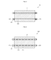
- FIG. 1 is a perspective view of a battery pack according to an embodiment of the present invention
- FIG. 2 is an exploded perspective view of the battery pack shown in FIG. 1 ;
- FIG. 3 is a cross-sectional view taken along the line A-A' of FIG. 2 ;
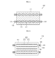
- FIG. 4 is a cross-sectional view illustrating a part of a battery pack corresponding to FIG. 3 , according to another embodiment of the present invention.
- FIG. 5 is a cross-sectional view illustrating a part of a battery pack corresponding to FIG. 3 , according to still another embodiment of the present invention.
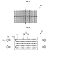
- FIG. 6 is a cross-sectional view illustrating a part of a battery pack corresponding to FIG. 3 , according to still another embodiment of the present invention.
- FIG. 7 is a plan view illustrating a reinforcement member shown in FIG. 6 ;
- FIG. 8 is a cross-sectional view illustrating a part of a battery pack corresponding to FIG. 3 , according to still another embodiment of the present invention.
- FIG. 1 is a perspective view of a battery pack according to an embodiment of the present invention
- FIG. 2 is an exploded perspective view of the battery pack shown in FIG. 1
- FIG. 3 is a cross-sectional view taken along the line A-A' of FIG. 2 .
- the battery pack 100 includes a plurality of battery cells 110, a frame 120 and an end plate 130.
- the plurality of battery cells 110 may be stacked together, and are connected to each other in series or parallel by an electrical connection member.
- the plurality of battery cells 110 are configured to be connected or coupled to external electronic devices and to perform discharge operations for supplying power to the external electronic devices or charge operations for receiving power from the external electronic devices.
- Each of the plurality of battery cells 110 includes an electrode assembly 111 having a positive electrode plate and a negative electrode plate with a separator located therebetween, a case 112 providing for a space in which the electrode assembly 111 is housed, a cap assembly 113 coupled to the case 112 to hermetically sealing the case 112, and a positive electrode terminal 114 and a negative electrode terminal 115 electrically connected to the positive electrode plate and the negative electrode plate, respectively, and protruding from the cap assembly 113.
- an insulator 101 having a relatively small thickness may be located between two adjacent battery cells 110 to prevent an unnecessary short-circuit.
- a thin insulator 101 may be attached to an outer surface of the outermost batter cell of the plurality of battery cells 110.
- an upper direction in which the positive electrode terminal 114 and the negative electrode terminal 115 are exposed from the battery cell 110 is referred to as an upper direction.
- the frame 120 is formed to cover the plurality of battery cells 110, and to fix the plurality of battery cells 110 and protect the same from external impact.
- the frame 120 includes a supporting member 121 and a reinforcement member 123 coupled to each other by, for example, insert molding.
- the insert molding is a technique of combining components made of two different materials into one body.
- the supporting member 121 forms the external appearance of the frame 120.
- the supporting member 121 includes a bottom portion 121 a covering the bottom portion of the plurality of battery cells 110, and a sidewall portion 121 b bent and extending from both sides of the bottom portion 121 a to cover both sides of the plurality of battery cells 110.
- the supporting member 121 serves to support the shape of the frame 120.
- the supporting member 121 may be made of an insulating resin that is substantially indeformable.
- the reinforcement member 123 is formed within the supporting member 121 and serves to reinforce the strength of the frame 120.
- the reinforcement member 123 may be made of a metal having high strength, for example, stainless steel.
- the reinforcement member 123 may be at least one restraint rod positioned at the sidewall portion 121b of the supporting member 121. A portion of the reinforcement member 123 is exposed from the supporting member 121 to then pass through the end plate 130.
- the reinforcement member 123 includes a base portion 124, an extending portion 125, and a screw thread 126.
- FIG. 3 shows a portion of the sidewall portion 121 b of the supporting member 121, in which the reinforcement member 123 is positioned.
- the base portion 124 is a bar extends in a direction substantially parallel to a direction in which the plurality of battery cells 110 are stacked.
- the extending portion 125 extends from the base portion 124 so as to be exposed from the supporting member 121 and passes through the end plate 130.
- the screw thread 126 is formed on the outer surface of the extending portion 125 and allows the nut 135 to be fastened with the extending portion 125.
- the frame 120 is formed such that the supporting member 121 and the reinforcement member 123 are coupled to each other by, for example, insert molding, thereby simplifying the manufacturing process of the battery pack 100 and achieving a compact dimension of the battery pack 100.
- the supporting member 121 and the reinforcement member 123 of the frame 120 are formed using different materials, the stress applied to the battery pack 100 can be dispersed.
- the reinforcement member 123 is made of a metallic material and the supporting member 121 is made of an insulating resin, the frame 120 may improve the heat dissipation capability and the insulating capability of the battery pack 100.
- the frame 120 of the embodiments of the present invention may have increased mechanical strength and is capable of maintaining the shape of the battery pack 100 while minimizing a weight of the battery pack 100, unlike a frame made of only a metal.
- the end plate 130 is formed to cover exterior sides of the plurality of battery cells 110, specifically, both sides that are not covered by the frame 120, and is coupled to the frame 120 to then be fixed.
- the end plate 130 fixes the plurality of battery cells 110 together with the frame 120.
- the end plate 130 may be made of a metal or a resin, and may include a plate portion 131, a bent portion 132, and a opening 133.
- the plate portion 131 faces and covers the battery cell 110 and is coupled to the frame 120.
- the bent portion 132 is bent and extends from both edges of the plate portion 131.
- the bent portion 132 reinforces the mechanical strength of the end plate 130, thereby preventing the end plate 130 from being significantly bent due to an external force.
- the opening133 is formed at a region of the plate portion 131 generally corresponding to the extending portion 125 of the reinforcement member 123, and the extending portion 125 of the reinforcement member 123 is inserted into the opening 133.
- the end plate 130 is fixedly coupled to the frame 120 such that the extending portion 125 of the reinforcement member 123 is inserted into the opening 133 of the end plate 130 and the nut 135 is fastened with the extending portion 125 through the screw thread 126 of the reinforcement member 123.
- the battery pack 100 includes the frame 120 having the supporting member 121 and the reinforcement member 123 coupled to each other by, for example, insert molding, thereby simplifying the manufacturing process thereof while minimizing a size of the battery pack.
- the supporting member 121 and the reinforcement member 123 are formed using different materials, the stress applied due to an external force can be dispersed.
- the supporting member 121 is made of an insulating resin and the reinforcement member 123 is made of a metallic material, the heat dissipation capability and the insulating capability of the battery pack 100 can be improved, and shape maintaining capability and minimized weight of the battery pack 100 can also be achieved while increasing mechanical strength of the battery pack 100.
- a battery pack corresponding to FIG. 4 according to another embodiment of the present invention will now be described.
- FIG. 4 is a cross-sectional view illustrating a part of a battery pack generally corresponding to FIG. 3 , according to another embodiment of the present invention.
- the battery pack according to this embodiment is substantially the same as the battery pack 100 according to the previous embodiment in view of configuration and function, except for the shape of a reinforcement member 223 of a frame 220, and therefore a description of the similar components will be omitted. In the following, the battery pack according to this embodiment will be described with regard to the reinforcement member 223 of the frame 220.
- the frame 220 is formed by coupling a supporting member 121 and the reinforcement member 223 to each other by, for example, insert molding.
- the reinforcement member 223 is substantially the same as the reinforcement member 123 shown in FIG. 3 , except that it further includes a plurality of coupling grooves 227 formed on the outer surface of a base portion 124.
- the plurality of coupling grooves 227 allow the supporting member 121 to be filled to be securely fixed.
- the battery pack according to the embodiment further includes the plurality of coupling grooves 227 formed in the reinforcement member 223, thereby increasing coupling strength between the reinforcement member 223 and the supporting member 121 made of different materials.
- a battery pack according to still another embodiment of the present invention will now be described.
- FIG. 5 is a cross-sectional view illustrating a part of a battery pack according to still another embodiment of the present invention, the part corresponding to FIG. 3 .
- the battery pack according to this embodiment is substantially the same with the battery pack 100 according to the previous embodiment in view of configuration and function, except for the shape of a reinforcement member 323 of a frame 320, and a description of the similar components will be omitted. In the following, the battery pack according to this embodiment will be described with regard to the reinforcement member 323 of the frame 320.
- the frame 320 is formed by coupling a supporting member 121 and the reinforcement member 323 to each other by, for example, insert molding.
- the reinforcement member 323 is substantially the same as the reinforcement member 123 shown in FIG. 3 , except that it further includes a plurality of coupling protrusions 327 formed on the outer surface of a base portion 124.
- the plurality of coupling protrusions 327 serve as supporters resisting against external forces while increasing coupling strength between the reinforcement member 323 and the supporting member 121 made of different materials.
- the battery pack according to the embodiment further includes the plurality of coupling protrusions 327 formed in the reinforcement member 323, thereby further increasing coupling strength between the reinforcement member 323 and the supporting member 121 made of different materials and increasing resistance against external forces.
- FIG. 6 is a cross-sectional view illustrating a part of a battery pack according to still another embodiment of the present invention, the part corresponding to FIG. 3
- FIG. 7 is a plan view illustrating a reinforcement member shown in FIG. 6 .
- the battery pack according to this embodiment is substantially the same with the battery pack 100 according to the previous embodiment in view of configuration and function, except for the shape of a reinforcement member 423 of a frame 420, and a description of the similar components will be omitted.
- the battery pack according to this embodiment will be described with regard to the reinforcement member 423 of the frame 420, and a connection member 426.
- the frame 420 is formed by coupling a supporting member 121, the reinforcement member 423 and the connection member 426 by, for example, insert molding.
- the reinforcement member 423 is formed within the supporting member 121 and reinforces mechanical strength of the frame 420.
- the reinforcement member 423 may be made of a metal having high strength, for example, stainless steel.
- the reinforcement member 423 may be formed in a mesh type.
- the reinforcement member 423 includes a first metal line 424 and a second metal line 425. The reinforcement member 423 is formed throughout a sidewall portion of the supporting member 121, thereby further increasing mechanical strength of the frame 420.
- connection member 426 may be formed at a region corresponding to the opening 133 of the end plate (130 of FIG. 2 ) in the frame 420, and may be a bolt.
- the connection member 426 includes a base portion 427 formed outside the reinforcement member 423 within the supporting member 121, an extending portion 428 exposed to one side of the supporting member 121, and a screw thread 429 formed on the outer surface of the extending portion 428.
- the extending portion 428 of the connection member 426 is inserted into the opening 133 of the end plate 130 and a nut (135 of FIG. 2 ) is fastened with the extending portion 428 through the screw thread 429, thereby allowing the end plate 130 to be fixedly coupled to the frame 420.
- the battery pack according to the embodiment includes the mesh-type reinforcement member 423 throughout the sidewall portion of the supporting member 121, thereby further increasing the mechanical strength of the frame 420 and ultimately further increasing resistance against external forces.
- a battery pack according to still another embodiment of the present invention will now be described.
- FIG. 8 is a cross-sectional view illustrating a part of a battery pack according to still another embodiment of the present invention, the part generally corresponding to FIG. 3 .
- the battery pack according to this embodiment is substantially the same as the battery pack 100 according to the previous embodiment in view of configuration and function, except that the shape of a reinforcement member 423 of a frame 520, and a connection member 523 and a bolt 535 are further provided. As such, a description of the similar components will be omitted. In the following, the battery pack according to this embodiment will be described with regard to the reinforcement member 423 of the frame 520, the connection member 523 and the bolt 535.
- the frame 520 is formed by coupling a supporting member 121, the reinforcement member 423 and the connection member 523 to each other by, for example, insert molding.
- connection member 523 may be formed at a region corresponding to the opening 133 of the end plate (130 of FIG. 2 ) in the frame 520, and may be a nut.
- the connection member 523 is formed outside the reinforcement member 423 within the supporting member 121 so as to be exposed from one side of the supporting member 121.
- the bolt 535 includes a screw thread 536 formed on a portion of its outer surface, and passes through the opening 133 of the end plate (130 of FIG. 2 ) to then be fastened with the connection member 523, thereby allowing the frame 520 to be fixedly coupled to the end plate (130 of FIG. 2 ). Since the bolt 535 is used in coupling the frame 520 and the end plate (130 of FIG. 2 ), the nut 135 of FIG. 2 may be omitted.
- the battery pack according to the embodiment includes the mesh-type reinforcement member 423 throughout the sidewall portion of the supporting member 121, thereby further increasing the mechanical strength of the frame 520 and ultimately further increasing resistance against external forces.
Abstract
Description
- The present invention relates to a battery pack.
- In general, secondary batteries are capable of being charged and discharged and can be repeatedly used. Low-capacity secondary batteries, each including a single unit cell, are widely used in small portable electronic devices, such as mobile phones, notebook type computers, cameras, camcorders, and the like. On the other hand, large-capacity secondary batteries, each including multiple battery cells, may be used as motor driving power sources, such as a hybrid electric vehicle (HEV), an electric vehicle (EV), an electric scooter, or the like.
- A battery pack includes various components including a plurality of battery cells, fixing members, a case, and so on. However, these components may impede attainment of compact and lightweight battery packs.
- According to one or more embodiments of the present invention, a battery pack includes a frame integrated with a reinforcement member and a supporting member, thereby providing a compact and lightweight dimension of the battery pack.
- One embodiment of the present invention provides a battery pack including a plurality of battery cells stacked together; a frame comprising a supporting member covering the battery cells and a reinforcement member within the supporting member; and an end plate on the battery cells and coupled to the frame.
- In one embodiment, the supporting member and the reinforcement member are made from different materials and are insert molded to each other. For example, the supporting member may be made from an insulating resin and the reinforcement member may be made from a metallic material. Further, a portion of the reinforcement member may protrude from the supporting member and extend through the end plate.
- In one embodiment, the supporting member includes a bottom portion covering one side of each of the plurality of battery cells; and a sidewall portion bent and extending from at least two sides of the bottom portion and covering two sides of each of the battery cells. The reinforcement member may be located in the sidewall portion and may include a base portion comprising a bar and extending in a direction generally parallel to a direction in which the battery cells are stacked; an extending portion extending from the base portion and protruding from the supporting member and passing through the end plate; and a screw thread on the extending portion.
- In one embodiment, the reinforcement member includes a plurality of coupling grooves and wherein the plurality of coupling grooves contain the supporting member. In another embodiment, the reinforcement member includes a plurality of coupling protrusions protruding from an outer surface of the reinforcement member. Further, the end plate may include a plate portion facing the plurality of battery cells and having an opening, wherein the reinforcement member extends through the opening; and a bent portion bent from and extending from two sides of the plate portion.
- As described above, the battery pack according to the embodiments of the present invention includes a frame having a reinforcement member and a supporting member coupled to each other by, for example, insert molding, thereby simplifying the manufacturing process and minimizing a size of the battery pack.
- In addition, the battery pack according to the embodiments of the present invention includes a reinforcement member and a supporting member made of different materials, thereby dispersing stress applied due to an external force.
- Further, the battery pack according to the embodiments of the present invention includes a reinforcement member made of a metallic material and a supporting member made of an insulating resin, thereby increasing mechanical strength, maintaining the shape and minimizing size while improving a heat dissipation capability and an insulating capability.
- Additional aspects of the invention will be set forth in part in the description that follows.
- The objects, features and advantages of the present invention will be more apparent from the following detailed description in conjunction with the accompanying drawings, in which:
-
FIG. 1 is a perspective view of a battery pack according to an embodiment of the present invention; -
FIG. 2 is an exploded perspective view of the battery pack shown inFIG. 1 ; -
FIG. 3 is a cross-sectional view taken along the line A-A' ofFIG. 2 ; -
FIG. 4 is a cross-sectional view illustrating a part of a battery pack corresponding toFIG. 3 , according to another embodiment of the present invention; -
FIG. 5 is a cross-sectional view illustrating a part of a battery pack corresponding toFIG. 3 , according to still another embodiment of the present invention; -
FIG. 6 is a cross-sectional view illustrating a part of a battery pack corresponding toFIG. 3 , according to still another embodiment of the present invention; -
FIG. 7 is a plan view illustrating a reinforcement member shown inFIG. 6 ; and -
FIG. 8 is a cross-sectional view illustrating a part of a battery pack corresponding toFIG. 3 , according to still another embodiment of the present invention. - Hereinafter, embodiments of the present invention will be described in detail with reference to the accompanying drawings.
-
FIG. 1 is a perspective view of a battery pack according to an embodiment of the present invention,FIG. 2 is an exploded perspective view of the battery pack shown inFIG. 1 , andFIG. 3 is a cross-sectional view taken along the line A-A' ofFIG. 2 . - Referring to
FIGS. 1 and2 , thebattery pack 100 according to an embodiment of the present invention includes a plurality ofbattery cells 110, aframe 120 and anend plate 130. - The plurality of
battery cells 110 may be stacked together, and are connected to each other in series or parallel by an electrical connection member. The plurality ofbattery cells 110 are configured to be connected or coupled to external electronic devices and to perform discharge operations for supplying power to the external electronic devices or charge operations for receiving power from the external electronic devices. - Each of the plurality of
battery cells 110 includes anelectrode assembly 111 having a positive electrode plate and a negative electrode plate with a separator located therebetween, acase 112 providing for a space in which theelectrode assembly 111 is housed, acap assembly 113 coupled to thecase 112 to hermetically sealing thecase 112, and apositive electrode terminal 114 and anegative electrode terminal 115 electrically connected to the positive electrode plate and the negative electrode plate, respectively, and protruding from thecap assembly 113. Here, aninsulator 101 having a relatively small thickness may be located between twoadjacent battery cells 110 to prevent an unnecessary short-circuit. In addition, athin insulator 101 may be attached to an outer surface of the outermost batter cell of the plurality ofbattery cells 110. In the following description of the current embodiment, a direction in which thepositive electrode terminal 114 and thenegative electrode terminal 115 are exposed from thebattery cell 110 is referred to as an upper direction. - The
frame 120 is formed to cover the plurality ofbattery cells 110, and to fix the plurality ofbattery cells 110 and protect the same from external impact. Theframe 120 includes a supportingmember 121 and areinforcement member 123 coupled to each other by, for example, insert molding. Here, the insert molding is a technique of combining components made of two different materials into one body. - The supporting
member 121 forms the external appearance of theframe 120. Specifically, the supportingmember 121 includes abottom portion 121 a covering the bottom portion of the plurality ofbattery cells 110, and asidewall portion 121 b bent and extending from both sides of thebottom portion 121 a to cover both sides of the plurality ofbattery cells 110. The supportingmember 121 serves to support the shape of theframe 120. To this end, the supportingmember 121 may be made of an insulating resin that is substantially indeformable. - The
reinforcement member 123 is formed within the supportingmember 121 and serves to reinforce the strength of theframe 120. To this end, thereinforcement member 123 may be made of a metal having high strength, for example, stainless steel. Here, thereinforcement member 123 may be at least one restraint rod positioned at thesidewall portion 121b of the supportingmember 121. A portion of thereinforcement member 123 is exposed from the supportingmember 121 to then pass through theend plate 130. - In detail, as shown in
FIG. 3 , thereinforcement member 123 includes abase portion 124, an extendingportion 125, and ascrew thread 126.FIG. 3 shows a portion of thesidewall portion 121 b of the supportingmember 121, in which thereinforcement member 123 is positioned. Thebase portion 124 is a bar extends in a direction substantially parallel to a direction in which the plurality ofbattery cells 110 are stacked. The extendingportion 125 extends from thebase portion 124 so as to be exposed from the supportingmember 121 and passes through theend plate 130. Thescrew thread 126 is formed on the outer surface of the extendingportion 125 and allows thenut 135 to be fastened with the extendingportion 125. - As described above, the
frame 120 is formed such that the supportingmember 121 and thereinforcement member 123 are coupled to each other by, for example, insert molding, thereby simplifying the manufacturing process of thebattery pack 100 and achieving a compact dimension of thebattery pack 100. In addition, since the supportingmember 121 and thereinforcement member 123 of theframe 120 are formed using different materials, the stress applied to thebattery pack 100 can be dispersed. Further, since thereinforcement member 123 is made of a metallic material and the supportingmember 121 is made of an insulating resin, theframe 120 may improve the heat dissipation capability and the insulating capability of thebattery pack 100. Further, compared to a frame made of only a resin, theframe 120 of the embodiments of the present invention may have increased mechanical strength and is capable of maintaining the shape of thebattery pack 100 while minimizing a weight of thebattery pack 100, unlike a frame made of only a metal. - With reference again to
FIG. 2 , theend plate 130 is formed to cover exterior sides of the plurality ofbattery cells 110, specifically, both sides that are not covered by theframe 120, and is coupled to theframe 120 to then be fixed. Theend plate 130 fixes the plurality ofbattery cells 110 together with theframe 120. Theend plate 130 may be made of a metal or a resin, and may include aplate portion 131, abent portion 132, and aopening 133. - The
plate portion 131 faces and covers thebattery cell 110 and is coupled to theframe 120. - The
bent portion 132 is bent and extends from both edges of theplate portion 131. Thebent portion 132 reinforces the mechanical strength of theend plate 130, thereby preventing theend plate 130 from being significantly bent due to an external force. - The opening133 is formed at a region of the
plate portion 131 generally corresponding to the extendingportion 125 of thereinforcement member 123, and the extendingportion 125 of thereinforcement member 123 is inserted into theopening 133. - The
end plate 130 is fixedly coupled to theframe 120 such that the extendingportion 125 of thereinforcement member 123 is inserted into theopening 133 of theend plate 130 and thenut 135 is fastened with the extendingportion 125 through thescrew thread 126 of thereinforcement member 123. - As described above, the
battery pack 100 according to the embodiment of the present invention includes theframe 120 having the supportingmember 121 and thereinforcement member 123 coupled to each other by, for example, insert molding, thereby simplifying the manufacturing process thereof while minimizing a size of the battery pack. - In addition, in the
battery pack 100 according to the embodiment of the present invention, since the supportingmember 121 and thereinforcement member 123 are formed using different materials, the stress applied due to an external force can be dispersed. - Further, in the
battery pack 100 according to the embodiment of the present invention, because the supportingmember 121 is made of an insulating resin and thereinforcement member 123 is made of a metallic material, the heat dissipation capability and the insulating capability of thebattery pack 100 can be improved, and shape maintaining capability and minimized weight of thebattery pack 100 can also be achieved while increasing mechanical strength of thebattery pack 100. - A battery pack corresponding to
FIG. 4 , according to another embodiment of the present invention will now be described. -
FIG. 4 is a cross-sectional view illustrating a part of a battery pack generally corresponding toFIG. 3 , according to another embodiment of the present invention. - The battery pack according to this embodiment is substantially the same as the
battery pack 100 according to the previous embodiment in view of configuration and function, except for the shape of areinforcement member 223 of aframe 220, and therefore a description of the similar components will be omitted. In the following, the battery pack according to this embodiment will be described with regard to thereinforcement member 223 of theframe 220. - Referring to
FIG. 4 , theframe 220 is formed by coupling a supportingmember 121 and thereinforcement member 223 to each other by, for example, insert molding. - The
reinforcement member 223 is substantially the same as thereinforcement member 123 shown inFIG. 3 , except that it further includes a plurality ofcoupling grooves 227 formed on the outer surface of abase portion 124. The plurality ofcoupling grooves 227 allow the supportingmember 121 to be filled to be securely fixed. - As described above, the battery pack according to the embodiment further includes the plurality of
coupling grooves 227 formed in thereinforcement member 223, thereby increasing coupling strength between thereinforcement member 223 and the supportingmember 121 made of different materials. - A battery pack according to still another embodiment of the present invention will now be described.
-
FIG. 5 is a cross-sectional view illustrating a part of a battery pack according to still another embodiment of the present invention, the part corresponding toFIG. 3 . - The battery pack according to this embodiment is substantially the same with the
battery pack 100 according to the previous embodiment in view of configuration and function, except for the shape of areinforcement member 323 of aframe 320, and a description of the similar components will be omitted. In the following, the battery pack according to this embodiment will be described with regard to thereinforcement member 323 of theframe 320. - Referring to
FIG. 5 , theframe 320 is formed by coupling a supportingmember 121 and thereinforcement member 323 to each other by, for example, insert molding. - The
reinforcement member 323 is substantially the same as thereinforcement member 123 shown inFIG. 3 , except that it further includes a plurality ofcoupling protrusions 327 formed on the outer surface of abase portion 124. The plurality ofcoupling protrusions 327 serve as supporters resisting against external forces while increasing coupling strength between thereinforcement member 323 and the supportingmember 121 made of different materials. - As described above, the battery pack according to the embodiment further includes the plurality of
coupling protrusions 327 formed in thereinforcement member 323, thereby further increasing coupling strength between thereinforcement member 323 and the supportingmember 121 made of different materials and increasing resistance against external forces. - Next, a battery pack according to still another embodiment of the present invention will be described.
-
FIG. 6 is a cross-sectional view illustrating a part of a battery pack according to still another embodiment of the present invention, the part corresponding toFIG. 3 , andFIG. 7 is a plan view illustrating a reinforcement member shown inFIG. 6 . - The battery pack according to this embodiment is substantially the same with the
battery pack 100 according to the previous embodiment in view of configuration and function, except for the shape of areinforcement member 423 of aframe 420, and a description of the similar components will be omitted. In the following, the battery pack according to this embodiment will be described with regard to thereinforcement member 423 of theframe 420, and aconnection member 426. - Referring to
FIGS. 6 and7 , theframe 420 is formed by coupling a supportingmember 121, thereinforcement member 423 and theconnection member 426 by, for example, insert molding. - The
reinforcement member 423 is formed within the supportingmember 121 and reinforces mechanical strength of theframe 420. To this end, thereinforcement member 423 may be made of a metal having high strength, for example, stainless steel. Here, thereinforcement member 423 may be formed in a mesh type. Specifically, thereinforcement member 423 includes afirst metal line 424 and asecond metal line 425. Thereinforcement member 423 is formed throughout a sidewall portion of the supportingmember 121, thereby further increasing mechanical strength of theframe 420. - The
connection member 426 may be formed at a region corresponding to theopening 133 of the end plate (130 ofFIG. 2 ) in theframe 420, and may be a bolt. Theconnection member 426 includes abase portion 427 formed outside thereinforcement member 423 within the supportingmember 121, an extendingportion 428 exposed to one side of the supportingmember 121, and ascrew thread 429 formed on the outer surface of the extendingportion 428. The extendingportion 428 of theconnection member 426 is inserted into theopening 133 of theend plate 130 and a nut (135 ofFIG. 2 ) is fastened with the extendingportion 428 through thescrew thread 429, thereby allowing theend plate 130 to be fixedly coupled to theframe 420. - As described above, the battery pack according to the embodiment includes the mesh-
type reinforcement member 423 throughout the sidewall portion of the supportingmember 121, thereby further increasing the mechanical strength of theframe 420 and ultimately further increasing resistance against external forces. - A battery pack according to still another embodiment of the present invention will now be described.
-
FIG. 8 is a cross-sectional view illustrating a part of a battery pack according to still another embodiment of the present invention, the part generally corresponding toFIG. 3 . - The battery pack according to this embodiment is substantially the same as the
battery pack 100 according to the previous embodiment in view of configuration and function, except that the shape of areinforcement member 423 of aframe 520, and aconnection member 523 and abolt 535 are further provided. As such, a description of the similar components will be omitted. In the following, the battery pack according to this embodiment will be described with regard to thereinforcement member 423 of theframe 520, theconnection member 523 and thebolt 535. - Referring to
FIG. 8 , theframe 520 is formed by coupling a supportingmember 121, thereinforcement member 423 and theconnection member 523 to each other by, for example, insert molding. - Since the
reinforcement member 423 is substantially the same as previously described with reference toFIG. 6 , it will not be described again. - The
connection member 523 may be formed at a region corresponding to theopening 133 of the end plate (130 ofFIG. 2 ) in theframe 520, and may be a nut. Theconnection member 523 is formed outside thereinforcement member 423 within the supportingmember 121 so as to be exposed from one side of the supportingmember 121. - The
bolt 535 includes ascrew thread 536 formed on a portion of its outer surface, and passes through theopening 133 of the end plate (130 ofFIG. 2 ) to then be fastened with theconnection member 523, thereby allowing theframe 520 to be fixedly coupled to the end plate (130 ofFIG. 2 ). Since thebolt 535 is used in coupling theframe 520 and the end plate (130 ofFIG. 2 ), thenut 135 ofFIG. 2 may be omitted. - As described above, the battery pack according to the embodiment includes the mesh-
type reinforcement member 423 throughout the sidewall portion of the supportingmember 121, thereby further increasing the mechanical strength of theframe 520 and ultimately further increasing resistance against external forces. - Although the battery pack according to the present invention has been illustrated through particular embodiments, it should be understood that many variations and modifications may be made in those embodiments within the scope of the present invention.
Claims (15)
- A battery pack (100) comprising:a plurality of battery cells (110) stacked together;a frame (120, 220, 320, 420, 520) comprising a supporting member (121) covering the battery cells (110) and a reinforcement member (123, 223, 323, 423) within the supporting member (121); andan end plate (130) on the battery cells (110) and coupled to the frame (120, 220, 320, 420, 520).
- The battery pack of claim 1, wherein the supporting member (121) and the reinforcement member (123, 223, 323, 423) comprise different materials; and/or wherein the supporting member (121) and the reinforcement member (123, 223, 323, 423) are insert molded to each other.
- The battery pack of one of the preceding claims, wherein the supporting member (121) comprises an insulating resin.
- The battery pack of one of the preceding claims, wherein the reinforcement member (123, 223, 323, 423) comprises a metallic material.
- The battery pack of one of the preceding claims, wherein a portion of the reinforcement member (123, 223, 323) protrudes from the supporting member (121) and extends through the end plate (130).
- The battery pack of claim 5, further comprising a nut (135) on an exterior side of the end plate (130) and coupled to the reinforcement member (123, 223, 323).
- The battery pack of one of the preceding claims, wherein the supporting member (121) comprises:a bottom portion (121 a) covering one side of each of the plurality of battery cells (110); anda sidewall portion (121 b) bent and extending from at least two sides of the bottom portion (121 a) and covering two sides of each of the battery cells (110).
- The battery pack of one of the preceding claims, wherein the reinforcement member (123, 223, 323) comprises:a base portion (124) comprising a bar and extending in a direction generally parallel to a direction in which the battery cells are stacked;an extending portion (125) extending from the base portion and protruding from the supporting member (121) and passing through the end plate (130); anda screw thread (126) on the extending portion (125).
- The battery pack of one of the claims 1 through 8, wherein the reinforcement member (223) includes a plurality of coupling grooves and wherein the plurality of coupling grooves contain the supporting member (121).
- The battery pack of one of the claims 1 through 8s, wherein the reinforcement member (323) includes a plurality of coupling protrusions protruding from an outer surface of the reinforcement member (323).
- The battery pack of claim 1, wherein the end plate (130) comprises:a plate portion (131) facing the plurality of battery cells (110) and having an opening (133), wherein the reinforcement member (123, 223, 323, 423) extends through the opening (133); anda bent portion (132) bent from and extending from two sides of the plate portion (131).
- The battery pack of one of the preceding claims, further comprising a connection member (426, 523) on the reinforcement member (423), wherein the connection member (426, 523) is coupled to the end plate (130).
- The battery pack of claim 12, wherein the connection member (426) is a bolt passing through the end plate (130), and wherein the battery pack (100) further comprises a nut (135) coupled to the connection member (426) or wherein the connection member (523) is a nut, and wherein the battery pack (100) further comprises a bolt (535) extending through the end plate (130) and coupled to connection member (523).
- The battery pack of claim 12, wherein the reinforcement member (423) is a mesh type.
- The battery pack of claim 14, wherein the reinforcement member (423) comprises a first metal line (424) and a second metal line (425).
Applications Claiming Priority (1)
| Application Number | Priority Date | Filing Date | Title |
|---|---|---|---|
| KR1020100051137A KR101126889B1 (en) | 2010-05-31 | 2010-05-31 | Battery pack |
Publications (2)
| Publication Number | Publication Date |
|---|---|
| EP2390941A1 true EP2390941A1 (en) | 2011-11-30 |
| EP2390941B1 EP2390941B1 (en) | 2013-04-17 |
Family
ID=43827162
Family Applications (1)
| Application Number | Title | Priority Date | Filing Date |
|---|---|---|---|
| EP10194501.2A Active EP2390941B1 (en) | 2010-05-31 | 2010-12-10 | Battery pack |
Country Status (5)
| Country | Link |
|---|---|
| US (1) | US9368769B2 (en) |
| EP (1) | EP2390941B1 (en) |
| JP (1) | JP5352558B2 (en) |
| KR (1) | KR101126889B1 (en) |
| CN (1) | CN102263211B (en) |
Cited By (5)
| Publication number | Priority date | Publication date | Assignee | Title |
|---|---|---|---|---|
| EP2624330A1 (en) * | 2012-02-03 | 2013-08-07 | Samsung SDI Co., Ltd. | Battery Pack |
| EP2631965A1 (en) * | 2012-02-27 | 2013-08-28 | Samsung SDI Co., Ltd. | Battery module |
| FR2993522A1 (en) * | 2012-07-19 | 2014-01-24 | Renault Sa | Envelope for forming complete case to protect e.g. lithium-ion battery tray, in car, has full wall partially surrounding electrical equipment, where zone of wall includes thermoplastic polymer surrounding porous metal insert |
| EP2797137A3 (en) * | 2013-04-25 | 2015-02-18 | MAGNA STEYR Battery Systems GmbH & Co OG | Battery system |
| EP3793022A1 (en) * | 2019-09-16 | 2021-03-17 | Black & Decker Inc. | Battery pack |
Families Citing this family (10)
| Publication number | Priority date | Publication date | Assignee | Title |
|---|---|---|---|---|
| KR101117686B1 (en) * | 2009-12-28 | 2012-02-29 | 에스비리모티브 주식회사 | Battery module and battery pack having the same |
| DE102011076580A1 (en) | 2011-05-27 | 2012-11-29 | Bayerische Motoren Werke Aktiengesellschaft | Energy storage module of several prismatic storage cells |
| KR101306653B1 (en) * | 2013-03-22 | 2013-09-10 | 비스티온 인테리어스 코리아 주식회사 | A method for manufacturing of bma with injection mesh |
| US9608245B2 (en) | 2014-09-30 | 2017-03-28 | Johnson Controls Technology Company | System for providing structural integrity of a battery module |
| DE102017103653A1 (en) * | 2017-02-22 | 2018-08-23 | Thyssenkrupp Ag | Battery housing for a vehicle battery and chassis for an electric vehicle |
| US11811259B2 (en) | 2017-03-17 | 2023-11-07 | Renew Health Ltd | Power pack |
| JP6851020B2 (en) * | 2017-06-01 | 2021-03-31 | パナソニックIpマネジメント株式会社 | Storage battery unit |
| CN108321314A (en) * | 2018-01-18 | 2018-07-24 | 湖南三迅新能源科技有限公司 | Lightweight power battery pack |
| KR102250204B1 (en) | 2018-03-07 | 2021-05-10 | 주식회사 엘지화학 | Battery module, battery pack comprising the battery module and vehicle comprising the battery pack |
| KR101944718B1 (en) * | 2018-07-05 | 2019-02-01 | (주)상아프론테크 | Insert structure and cassette for loading substrate with the same |
Citations (4)
| Publication number | Priority date | Publication date | Assignee | Title |
|---|---|---|---|---|
| GB482363A (en) * | 1936-06-24 | 1938-03-24 | Frank Maccallum | Improvements relating to dry batteries |
| US5756227A (en) * | 1994-11-18 | 1998-05-26 | Honda Giken Kogyo Kabushiki Kaisha | Battery assembly with temperature control mechanism |
| EP1577966A2 (en) * | 2004-03-18 | 2005-09-21 | Fuji Jukogyo Kabushiki Kaisha | Accumulator device |
| US20060115719A1 (en) * | 2004-11-30 | 2006-06-01 | Yoon-Cheol Jeon | Secondary battery module and end-plate used in the same |
Family Cites Families (12)
| Publication number | Priority date | Publication date | Assignee | Title |
|---|---|---|---|---|
| FR1600393A (en) * | 1968-12-31 | 1970-07-20 | ||
| GB1488116A (en) | 1974-12-19 | 1977-10-05 | Chloride Lorival Ltd | Formation of generally rectangular containers |
| US5492779A (en) | 1994-10-24 | 1996-02-20 | General Motors Corporation | Heat dissipating battery |
| KR100590049B1 (en) | 2004-11-30 | 2006-06-14 | 삼성에스디아이 주식회사 | Secondary battery module and end-plate |
| JP4513813B2 (en) | 2007-02-01 | 2010-07-28 | トヨタ自動車株式会社 | Power storage device |
| JP5147373B2 (en) | 2007-11-29 | 2013-02-20 | 三洋電機株式会社 | Battery system |
| JP2009238643A (en) | 2008-03-27 | 2009-10-15 | Sanyo Electric Co Ltd | Battery block for vehicle |
| JP5340659B2 (en) | 2008-07-07 | 2013-11-13 | 三洋電機株式会社 | Battery pack for vehicles |
| CN201311951Y (en) | 2008-10-09 | 2009-09-16 | 比亚迪股份有限公司 | Power battery pack |
| JP2010108788A (en) | 2008-10-30 | 2010-05-13 | Sanyo Electric Co Ltd | Battery system |
| JP5504724B2 (en) | 2009-07-17 | 2014-05-28 | 日産自動車株式会社 | Battery pack and manufacturing method thereof |
| US9065111B2 (en) | 2010-05-26 | 2015-06-23 | Samsung Sdi Co., Ltd. | Battery pack |
-
2010
- 2010-05-31 KR KR1020100051137A patent/KR101126889B1/en active IP Right Grant
- 2010-09-23 US US12/889,266 patent/US9368769B2/en active Active
- 2010-09-24 JP JP2010214109A patent/JP5352558B2/en active Active
- 2010-11-18 CN CN201010562900.7A patent/CN102263211B/en active Active
- 2010-12-10 EP EP10194501.2A patent/EP2390941B1/en active Active
Patent Citations (4)
| Publication number | Priority date | Publication date | Assignee | Title |
|---|---|---|---|---|
| GB482363A (en) * | 1936-06-24 | 1938-03-24 | Frank Maccallum | Improvements relating to dry batteries |
| US5756227A (en) * | 1994-11-18 | 1998-05-26 | Honda Giken Kogyo Kabushiki Kaisha | Battery assembly with temperature control mechanism |
| EP1577966A2 (en) * | 2004-03-18 | 2005-09-21 | Fuji Jukogyo Kabushiki Kaisha | Accumulator device |
| US20060115719A1 (en) * | 2004-11-30 | 2006-06-01 | Yoon-Cheol Jeon | Secondary battery module and end-plate used in the same |
Cited By (8)
| Publication number | Priority date | Publication date | Assignee | Title |
|---|---|---|---|---|
| EP2624330A1 (en) * | 2012-02-03 | 2013-08-07 | Samsung SDI Co., Ltd. | Battery Pack |
| US9660231B2 (en) | 2012-02-03 | 2017-05-23 | Samsung Sdi Co., Ltd. | Battery pack |
| EP2631965A1 (en) * | 2012-02-27 | 2013-08-28 | Samsung SDI Co., Ltd. | Battery module |
| FR2993522A1 (en) * | 2012-07-19 | 2014-01-24 | Renault Sa | Envelope for forming complete case to protect e.g. lithium-ion battery tray, in car, has full wall partially surrounding electrical equipment, where zone of wall includes thermoplastic polymer surrounding porous metal insert |
| EP2797137A3 (en) * | 2013-04-25 | 2015-02-18 | MAGNA STEYR Battery Systems GmbH & Co OG | Battery system |
| US10096807B2 (en) | 2013-04-25 | 2018-10-09 | Samsung Sdi Co., Ltd. | Battery system |
| EP3793022A1 (en) * | 2019-09-16 | 2021-03-17 | Black & Decker Inc. | Battery pack |
| US11901570B2 (en) | 2019-09-16 | 2024-02-13 | Black & Decker Inc. | Battery pack |
Also Published As
| Publication number | Publication date |
|---|---|
| CN102263211A (en) | 2011-11-30 |
| JP5352558B2 (en) | 2013-11-27 |
| US9368769B2 (en) | 2016-06-14 |
| US20110293978A1 (en) | 2011-12-01 |
| CN102263211B (en) | 2015-05-20 |
| KR20110131609A (en) | 2011-12-07 |
| KR101126889B1 (en) | 2012-03-20 |
| EP2390941B1 (en) | 2013-04-17 |
| JP2011253799A (en) | 2011-12-15 |
Similar Documents
| Publication | Publication Date | Title |
|---|---|---|
| US9368769B2 (en) | Battery pack | |
| US10236486B2 (en) | Rechargeable battery pack | |
| US11769925B2 (en) | Battery module having initial pressing force reinforcing structure for cell assembly and method of manufacturing the same | |
| US10243193B2 (en) | Battery pack | |
| EP3035434B1 (en) | Battery module | |
| US7811686B2 (en) | Rechargeable battery | |
| US7790313B2 (en) | Secondary battery | |
| US7781095B2 (en) | Rechargeable battery having current collecting plates coupled with uncoated regions of electrodes | |
| US20060068276A1 (en) | Collector plate for rechargeable battery, electrode assembly, and rechargeable battery comprising the same | |
| US20050221178A1 (en) | Electrode package and secondary battery using the same | |
| US20060063068A1 (en) | Secondary battery | |
| US20050089753A1 (en) | Secondary battery | |
| KR102619201B1 (en) | Secondary Battery and Battery Module Having the Same | |
| US20060068277A1 (en) | Secondary battery | |
| US20180047948A1 (en) | Battery cell | |
| US20160164051A1 (en) | Secondary battery and battery pack including the same | |
| EP2654097A1 (en) | Rechargeable battery | |
| US8586221B2 (en) | Rechargeable battery with protective circuit board lead plates connection | |
| US20060216595A1 (en) | Battery assembly having improved lug profile | |
| EP3896781B1 (en) | Rechargeable battery | |
| US8481193B2 (en) | Battery module and method of manufacturing the same | |
| EP4050715A1 (en) | Battery pack, electronic device, and vehicle | |
| EP4024592A2 (en) | Battery module | |
| JP7062211B2 (en) | Battery pack and devices containing it | |
| EP4266465A1 (en) | Battery module |
Legal Events
| Date | Code | Title | Description |
|---|---|---|---|
| 17P | Request for examination filed |
Effective date: 20101210 |
|
| AK | Designated contracting states |
Kind code of ref document: A1 Designated state(s): AL AT BE BG CH CY CZ DE DK EE ES FI FR GB GR HR HU IE IS IT LI LT LU LV MC MK MT NL NO PL PT RO RS SE SI SK SM TR |
|
| AX | Request for extension of the european patent |
Extension state: BA ME |
|
| PUAI | Public reference made under article 153(3) epc to a published international application that has entered the european phase |
Free format text: ORIGINAL CODE: 0009012 |
|
| 17Q | First examination report despatched |
Effective date: 20120309 |
|
| GRAP | Despatch of communication of intention to grant a patent |
Free format text: ORIGINAL CODE: EPIDOSNIGR1 |
|
| RAP1 | Party data changed (applicant data changed or rights of an application transferred) |
Owner name: SAMSUNG SDI CO., LTD. Owner name: ROBERT BOSCH GMBH |
|
| GRAS | Grant fee paid |
Free format text: ORIGINAL CODE: EPIDOSNIGR3 |
|
| GRAA | (expected) grant |
Free format text: ORIGINAL CODE: 0009210 |
|
| AK | Designated contracting states |
Kind code of ref document: B1 Designated state(s): AL AT BE BG CH CY CZ DE DK EE ES FI FR GB GR HR HU IE IS IT LI LT LU LV MC MK MT NL NO PL PT RO RS SE SI SK SM TR |
|
| REG | Reference to a national code |
Ref country code: GB Ref legal event code: FG4D |
|
| REG | Reference to a national code |
Ref country code: CH Ref legal event code: EP |
|
| REG | Reference to a national code |
Ref country code: IE Ref legal event code: FG4D |
|
| REG | Reference to a national code |
Ref country code: AT Ref legal event code: REF Ref document number: 607780 Country of ref document: AT Kind code of ref document: T Effective date: 20130515 |
|
| REG | Reference to a national code |
Ref country code: DE Ref legal event code: R096 Ref document number: 602010006238 Country of ref document: DE Effective date: 20130613 |
|
| REG | Reference to a national code |
Ref country code: AT Ref legal event code: MK05 Ref document number: 607780 Country of ref document: AT Kind code of ref document: T Effective date: 20130417 |
|
| REG | Reference to a national code |
Ref country code: LT Ref legal event code: MG4D |
|
| REG | Reference to a national code |
Ref country code: NL Ref legal event code: VDEP Effective date: 20130417 |
|
| PG25 | Lapsed in a contracting state [announced via postgrant information from national office to epo] |
Ref country code: SE Free format text: LAPSE BECAUSE OF FAILURE TO SUBMIT A TRANSLATION OF THE DESCRIPTION OR TO PAY THE FEE WITHIN THE PRESCRIBED TIME-LIMIT Effective date: 20130417 Ref country code: GR Free format text: LAPSE BECAUSE OF FAILURE TO SUBMIT A TRANSLATION OF THE DESCRIPTION OR TO PAY THE FEE WITHIN THE PRESCRIBED TIME-LIMIT Effective date: 20130718 Ref country code: LT Free format text: LAPSE BECAUSE OF FAILURE TO SUBMIT A TRANSLATION OF THE DESCRIPTION OR TO PAY THE FEE WITHIN THE PRESCRIBED TIME-LIMIT Effective date: 20130417 Ref country code: BE Free format text: LAPSE BECAUSE OF FAILURE TO SUBMIT A TRANSLATION OF THE DESCRIPTION OR TO PAY THE FEE WITHIN THE PRESCRIBED TIME-LIMIT Effective date: 20130417 Ref country code: FI Free format text: LAPSE BECAUSE OF FAILURE TO SUBMIT A TRANSLATION OF THE DESCRIPTION OR TO PAY THE FEE WITHIN THE PRESCRIBED TIME-LIMIT Effective date: 20130417 Ref country code: AT Free format text: LAPSE BECAUSE OF FAILURE TO SUBMIT A TRANSLATION OF THE DESCRIPTION OR TO PAY THE FEE WITHIN THE PRESCRIBED TIME-LIMIT Effective date: 20130417 Ref country code: NO Free format text: LAPSE BECAUSE OF FAILURE TO SUBMIT A TRANSLATION OF THE DESCRIPTION OR TO PAY THE FEE WITHIN THE PRESCRIBED TIME-LIMIT Effective date: 20130717 Ref country code: PT Free format text: LAPSE BECAUSE OF FAILURE TO SUBMIT A TRANSLATION OF THE DESCRIPTION OR TO PAY THE FEE WITHIN THE PRESCRIBED TIME-LIMIT Effective date: 20130819 Ref country code: IS Free format text: LAPSE BECAUSE OF FAILURE TO SUBMIT A TRANSLATION OF THE DESCRIPTION OR TO PAY THE FEE WITHIN THE PRESCRIBED TIME-LIMIT Effective date: 20130817 Ref country code: ES Free format text: LAPSE BECAUSE OF FAILURE TO SUBMIT A TRANSLATION OF THE DESCRIPTION OR TO PAY THE FEE WITHIN THE PRESCRIBED TIME-LIMIT Effective date: 20130728 Ref country code: SI Free format text: LAPSE BECAUSE OF FAILURE TO SUBMIT A TRANSLATION OF THE DESCRIPTION OR TO PAY THE FEE WITHIN THE PRESCRIBED TIME-LIMIT Effective date: 20130417 |
|
| PG25 | Lapsed in a contracting state [announced via postgrant information from national office to epo] |
Ref country code: RS Free format text: LAPSE BECAUSE OF FAILURE TO SUBMIT A TRANSLATION OF THE DESCRIPTION OR TO PAY THE FEE WITHIN THE PRESCRIBED TIME-LIMIT Effective date: 20130417 Ref country code: LV Free format text: LAPSE BECAUSE OF FAILURE TO SUBMIT A TRANSLATION OF THE DESCRIPTION OR TO PAY THE FEE WITHIN THE PRESCRIBED TIME-LIMIT Effective date: 20130417 Ref country code: CY Free format text: LAPSE BECAUSE OF FAILURE TO SUBMIT A TRANSLATION OF THE DESCRIPTION OR TO PAY THE FEE WITHIN THE PRESCRIBED TIME-LIMIT Effective date: 20130417 Ref country code: PL Free format text: LAPSE BECAUSE OF FAILURE TO SUBMIT A TRANSLATION OF THE DESCRIPTION OR TO PAY THE FEE WITHIN THE PRESCRIBED TIME-LIMIT Effective date: 20130417 Ref country code: HR Free format text: LAPSE BECAUSE OF FAILURE TO SUBMIT A TRANSLATION OF THE DESCRIPTION OR TO PAY THE FEE WITHIN THE PRESCRIBED TIME-LIMIT Effective date: 20130417 Ref country code: BG Free format text: LAPSE BECAUSE OF FAILURE TO SUBMIT A TRANSLATION OF THE DESCRIPTION OR TO PAY THE FEE WITHIN THE PRESCRIBED TIME-LIMIT Effective date: 20130717 |
|
| PG25 | Lapsed in a contracting state [announced via postgrant information from national office to epo] |
Ref country code: CZ Free format text: LAPSE BECAUSE OF FAILURE TO SUBMIT A TRANSLATION OF THE DESCRIPTION OR TO PAY THE FEE WITHIN THE PRESCRIBED TIME-LIMIT Effective date: 20130417 Ref country code: EE Free format text: LAPSE BECAUSE OF FAILURE TO SUBMIT A TRANSLATION OF THE DESCRIPTION OR TO PAY THE FEE WITHIN THE PRESCRIBED TIME-LIMIT Effective date: 20130417 Ref country code: DK Free format text: LAPSE BECAUSE OF FAILURE TO SUBMIT A TRANSLATION OF THE DESCRIPTION OR TO PAY THE FEE WITHIN THE PRESCRIBED TIME-LIMIT Effective date: 20130417 Ref country code: SK Free format text: LAPSE BECAUSE OF FAILURE TO SUBMIT A TRANSLATION OF THE DESCRIPTION OR TO PAY THE FEE WITHIN THE PRESCRIBED TIME-LIMIT Effective date: 20130417 |
|
| PLBE | No opposition filed within time limit |
Free format text: ORIGINAL CODE: 0009261 |
|
| STAA | Information on the status of an ep patent application or granted ep patent |
Free format text: STATUS: NO OPPOSITION FILED WITHIN TIME LIMIT |
|
| PG25 | Lapsed in a contracting state [announced via postgrant information from national office to epo] |
Ref country code: NL Free format text: LAPSE BECAUSE OF FAILURE TO SUBMIT A TRANSLATION OF THE DESCRIPTION OR TO PAY THE FEE WITHIN THE PRESCRIBED TIME-LIMIT Effective date: 20130417 Ref country code: IT Free format text: LAPSE BECAUSE OF FAILURE TO SUBMIT A TRANSLATION OF THE DESCRIPTION OR TO PAY THE FEE WITHIN THE PRESCRIBED TIME-LIMIT Effective date: 20130417 Ref country code: RO Free format text: LAPSE BECAUSE OF FAILURE TO SUBMIT A TRANSLATION OF THE DESCRIPTION OR TO PAY THE FEE WITHIN THE PRESCRIBED TIME-LIMIT Effective date: 20130417 |
|
| 26N | No opposition filed |
Effective date: 20140120 |
|
| REG | Reference to a national code |
Ref country code: DE Ref legal event code: R097 Ref document number: 602010006238 Country of ref document: DE Effective date: 20140120 |
|
| PG25 | Lapsed in a contracting state [announced via postgrant information from national office to epo] |
Ref country code: LU Free format text: LAPSE BECAUSE OF FAILURE TO SUBMIT A TRANSLATION OF THE DESCRIPTION OR TO PAY THE FEE WITHIN THE PRESCRIBED TIME-LIMIT Effective date: 20131210 |
|
| REG | Reference to a national code |
Ref country code: IE Ref legal event code: MM4A |
|
| PG25 | Lapsed in a contracting state [announced via postgrant information from national office to epo] |
Ref country code: IE Free format text: LAPSE BECAUSE OF NON-PAYMENT OF DUE FEES Effective date: 20131210 |
|
| PG25 | Lapsed in a contracting state [announced via postgrant information from national office to epo] |
Ref country code: MC Free format text: LAPSE BECAUSE OF FAILURE TO SUBMIT A TRANSLATION OF THE DESCRIPTION OR TO PAY THE FEE WITHIN THE PRESCRIBED TIME-LIMIT Effective date: 20130417 |
|
| PG25 | Lapsed in a contracting state [announced via postgrant information from national office to epo] |
Ref country code: SM Free format text: LAPSE BECAUSE OF FAILURE TO SUBMIT A TRANSLATION OF THE DESCRIPTION OR TO PAY THE FEE WITHIN THE PRESCRIBED TIME-LIMIT Effective date: 20130417 |
|
| PG25 | Lapsed in a contracting state [announced via postgrant information from national office to epo] |
Ref country code: TR Free format text: LAPSE BECAUSE OF FAILURE TO SUBMIT A TRANSLATION OF THE DESCRIPTION OR TO PAY THE FEE WITHIN THE PRESCRIBED TIME-LIMIT Effective date: 20130417 |
|
| PG25 | Lapsed in a contracting state [announced via postgrant information from national office to epo] |
Ref country code: HU Free format text: LAPSE BECAUSE OF FAILURE TO SUBMIT A TRANSLATION OF THE DESCRIPTION OR TO PAY THE FEE WITHIN THE PRESCRIBED TIME-LIMIT; INVALID AB INITIO Effective date: 20101210 Ref country code: MK Free format text: LAPSE BECAUSE OF FAILURE TO SUBMIT A TRANSLATION OF THE DESCRIPTION OR TO PAY THE FEE WITHIN THE PRESCRIBED TIME-LIMIT Effective date: 20130417 |
|
| REG | Reference to a national code |
Ref country code: CH Ref legal event code: PL |
|
| PG25 | Lapsed in a contracting state [announced via postgrant information from national office to epo] |
Ref country code: MT Free format text: LAPSE BECAUSE OF FAILURE TO SUBMIT A TRANSLATION OF THE DESCRIPTION OR TO PAY THE FEE WITHIN THE PRESCRIBED TIME-LIMIT Effective date: 20130417 |
|
| PG25 | Lapsed in a contracting state [announced via postgrant information from national office to epo] |
Ref country code: CH Free format text: LAPSE BECAUSE OF NON-PAYMENT OF DUE FEES Effective date: 20141231 Ref country code: LI Free format text: LAPSE BECAUSE OF NON-PAYMENT OF DUE FEES Effective date: 20141231 |
|
| REG | Reference to a national code |
Ref country code: FR Ref legal event code: PLFP Year of fee payment: 6 |
|
| REG | Reference to a national code |
Ref country code: FR Ref legal event code: PLFP Year of fee payment: 7 |
|
| REG | Reference to a national code |
Ref country code: FR Ref legal event code: PLFP Year of fee payment: 8 |
|
| PG25 | Lapsed in a contracting state [announced via postgrant information from national office to epo] |
Ref country code: AL Free format text: LAPSE BECAUSE OF FAILURE TO SUBMIT A TRANSLATION OF THE DESCRIPTION OR TO PAY THE FEE WITHIN THE PRESCRIBED TIME-LIMIT Effective date: 20130417 |
|
| REG | Reference to a national code |
Ref country code: DE Ref legal event code: R079 Ref document number: 602010006238 Country of ref document: DE Free format text: PREVIOUS MAIN CLASS: H01M0002100000 Ipc: H01M0050200000 |
|
| P01 | Opt-out of the competence of the unified patent court (upc) registered |
Effective date: 20230530 |
|
| PGFP | Annual fee paid to national office [announced via postgrant information from national office to epo] |
Ref country code: GB Payment date: 20231130 Year of fee payment: 14 |
|
| PGFP | Annual fee paid to national office [announced via postgrant information from national office to epo] |
Ref country code: FR Payment date: 20231212 Year of fee payment: 14 Ref country code: DE Payment date: 20231128 Year of fee payment: 14 |