EP2390617A1 - Détonateur sécurisé - Google Patents
Détonateur sécurisé Download PDFInfo
- Publication number
- EP2390617A1 EP2390617A1 EP11290241A EP11290241A EP2390617A1 EP 2390617 A1 EP2390617 A1 EP 2390617A1 EP 11290241 A EP11290241 A EP 11290241A EP 11290241 A EP11290241 A EP 11290241A EP 2390617 A1 EP2390617 A1 EP 2390617A1
- Authority
- EP
- European Patent Office
- Prior art keywords
- plate
- detonator
- composition
- stage
- temperature
- Prior art date
- Legal status (The legal status is an assumption and is not a legal conclusion. Google has not performed a legal analysis and makes no representation as to the accuracy of the status listed.)
- Granted
Links
Images
Classifications
-
- F—MECHANICAL ENGINEERING; LIGHTING; HEATING; WEAPONS; BLASTING
- F42—AMMUNITION; BLASTING
- F42B—EXPLOSIVE CHARGES, e.g. FOR BLASTING, FIREWORKS, AMMUNITION
- F42B3/00—Blasting cartridges, i.e. case and explosive
- F42B3/10—Initiators therefor
- F42B3/12—Bridge initiators
- F42B3/124—Bridge initiators characterised by the configuration or material of the bridge
-
- F—MECHANICAL ENGINEERING; LIGHTING; HEATING; WEAPONS; BLASTING
- F42—AMMUNITION; BLASTING
- F42B—EXPLOSIVE CHARGES, e.g. FOR BLASTING, FIREWORKS, AMMUNITION
- F42B3/00—Blasting cartridges, i.e. case and explosive
- F42B3/10—Initiators therefor
- F42B3/113—Initiators therefor activated by optical means, e.g. laser, flashlight
Definitions
- the technical field of the invention is that of detonators plate or projected element.
- This type of detonator as described in US6374740 comprises a body in which there is a first stage, or inflammatory stage, comprising at least a first pyrotechnic composition or an explosive secondary explosive.
- a relay stage comprising at least one secondary explosive.
- the first composition may be initiatable by an optical means such as an optical fiber or an electrical means (hot wire) while the secondary explosive is initiatable by an impact. This is why a thin metal plate is placed between the two pyrotechnic stages. Following the custom initiation of the first composition, the metal plate is projected onto the secondary explosive which will then be initiated following the energy of the shock provided by the plate.
- the first composition may react and cause the projection of the plate and thereby the reaction of the secondary explosive and the whole of the pyrotechnic chain.
- the invention proposes to set up a fuseplatable plate at a temperature below the instability temperature of the igniter stage.
- the subject of the invention is a detonator comprising a plate projected by an igniter stage comprising at least a first pyrotechnic composition and / or a first explosive on a relay stage comprising at least one secondary explosive, a detonator characterized in that the plate projected is made of a fusible material at a temperature below the instability temperature of the igniter stage.
- the melting temperature T of the plate is at least 15 ° C. lower than the instability temperature of the igniter stage.
- the plate may be made of a tin-based alloy.
- the first pyrotechnic composition of the igniter stage may be in contact with the end of an optical fiber.
- the detonator 1 comprises a substantially cylindrical body 2 having three parts 2a, 2b and 2c.
- the central portion 2b of the body has an external thread 2d for securing the detonator with a mounting for receiving it such as a munition (mounting not shown).
- a sheathed optical fiber 3 passes through the rear part 2a of the body.
- the optical fiber 3 opens in contact with a first pyrotechnic composition 4 photosensitive forming here the igniter stage of the detonator.
- a first pyrotechnic composition 4 photosensitive forming here the igniter stage of the detonator.
- a first pyrotechnic composition 4 a composition combining zirconium and potassium perchlorate. Such a composition is conventional and it is not necessary to describe it in more detail.
- Other types of pyrotechnic compositions may be used such as: boron / potassium nitrate, boron / zirconium / potassium nitrate .
- the secondary explosive may be pure or incorporate an optical dopant as described by the patent EP1742009 .
- a layer of pyrotechnic ignition composition (such as a zirconium / potassium perchlorate composition) in contact with the optical fiber and which ignites a layer of a secondary explosive will be associated with the ignor stage. explosion, for example octogen.
- pyrotechnic ignition composition such as a zirconium / potassium perchlorate composition
- the patent EP1306643 describes such an association of an ignition composition and a secondary explosive.
- the igniter stage comprises a first composition (and / or a secondary explosive explosion) having a particle size perfectly controlled and relatively reduced (less than or equal to 60 micrometers).
- This first pyrotechnic composition 4 is loaded into a case 5 whose bottom comprises a projectable metal plate 6 (also called projected element 6).
- the case 5 has an annular area surrounding the rear portion 2a of the body and is welded to the rear portion 2a to seal.
- the case 5 is thus held in position by a thread 9 solidarisant the rear part of the body 2a to the central part of the body 2b.
- the metal plate 6 is supported by its periphery on a shoulder of the front portion 2c of the body 2.
- a secondary explosive 7 sensitive to shock which forms a relay stage.
- the distance D will be chosen by the person skilled in the art as being that which makes it possible to obtain the optimal projection speed at the shock release of the secondary explosive 7 by virtue of the characteristics of the igniter stage, and therefore especially of the nature and the mass of the first composition 4 and the mass of the plate.
- the invention proposes that the projectable metal plate is made of a metal or metal alloy whose melting temperature is at least 15 ° C lower than the reaction temperature of the metal.
- the inflammatory stage thus here the first pyrotechnic composition 4 or, in the case of an inflammatory stage comprising several layers, less than the reaction temperature of the most temperature-sensitive layer (usually the explosive secondary explosive layer).
- the pyrotechnic compositions and secondary explosives commonly used in this type of detonator which are thermally stable up to at least 230 ° C, the following examples of alloys can be used for producing the projectable plate.
- lead alloys are also feasible but is not to be favored for environmental and normative reasons.
- the figure 2 shows the detonator 2 when it has been subjected to a temperature of the order of 215 ° C., ie approximately 15 ° below the reaction temperature of the first pyrotechnic composition 4.
- the projectable metal plate 6 has melted at this temperature T while the first composition 4 has remained stable. If the temperature continues to increase up to the instability temperature of the first composition 4, it will react but it will not be able to project the plate 6 which will not cause the detonation of the explosive 7. In the case the most unfavorable, the secondary explosive 7 will be able to deflagrate what will not be enough to trigger the continuation of the pyrotechnic chain.
- the plate 6 as a pinch between the case 5 and the front portion 2c of the body 2.
- the plate 6 could be secured to the case and form for example a closing flap closing this case. In this case the outer edge of the case will be crimped on the plate 6.
- the invention has also been described with an igniter stage initiated by an optical fiber.
- the invention can also be implemented with an igniter stage initiated in a more conventional manner by the electrical energy, for example a hot-wire or exploded-wire igniter.
Landscapes
- Engineering & Computer Science (AREA)
- General Engineering & Computer Science (AREA)
- Physics & Mathematics (AREA)
- Optics & Photonics (AREA)
- Air Bags (AREA)
Abstract
Description
- Le domaine technique de l'invention est celui des détonateurs à plaque ou élément projeté.
- Ce type de détonateur tel que décrit dans
US6374740 comporte un corps dans lequel se trouve un premier étage, ou étage inflammateur, comprenant au moins une première composition pyrotechnique ou un explosif secondaire déflagrant. En regard de ce premier étage inflammateur se trouve un étage relais comprenant au moins un explosif secondaire. La première composition peut être initiable par un moyen optique tel qu'une fibre optique ou un moyen électrique (fil chaud) alors que l'explosif secondaire est initiable par un choc. C'est pourquoi une plaque de métal mince est placée entre les deux étages pyrotechniques. Suite à l'initiation sur commande de la première composition, la plaque de métal est projetée sur l'explosif secondaire qui va alors s'initier suite à l'énergie du choc fourni par la plaque. - Ce fonctionnement présente un inconvénient sécuritaire. En cas d'exposition du détonateur à une forte chaleur due à un incendie par exemple, la première composition risque de réagir et de provoquer la projection de la plaque et par-là même la réaction de l'explosif secondaire et de l'ensemble de la chaine pyrotechnique.
- Pour remédier à ce problème, l'invention se propose de mettre en place une plaque projetable fusible à une température inférieure à la température d'instabilité de l'étage inflammateur.
- Ainsi l'invention à pour objet un détonateur comportant une plaque projetée par un étage inflammateur comprenant au moins une première composition pyrotechnique et/ou un premier explosif sur un étage relais comprenant au moins un explosif secondaire, détonateur caractérisé en ce que la plaque projetée est réalisée en un matériau fusible à une température inférieure à la température d'instabilité de l'étage inflammateur.
- Avantageusement, la température T de fusion de la plaque est inférieure d'au moins 15°C à la température d'instabilité de l'étage inflammateur.
- La plaque pourra être réalisée en un alliage à base d'étain.
- Selon différents modes de réalisation, la plaque pourra être réalisée en un alliage choisi parmi les alliages ayant les compositions suivantes :
- SnAg3.4Bi4.8 ou SnBi7.5Ag2.0 ou SnZn9 ou SnZn8Bi3.
- Selon un mode particulier de réalisation, la première composition pyrotechnique de l'étage inflammateur pourra être en contact avec l'extrémité d'une fibre optique.
- L'invention sera mieux comprise à la lecture de la description suivante, description illustrée par les dessins annexés dans lesquels :
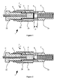
- La
figure 1 représente un détonateur en coupe longitudinale avant fusion de la plaque. - La
figure 2 représente un détonateur en coupe longitudinale après fusion de la plaque. - Selon la
figure 1 , et selon un mode de réalisation, le détonateur 1 comporte un corps 2 sensiblement cylindrique comportant trois parties 2a, 2b et 2c. La partie centrale 2b du corps comporte un filetage externe 2d permettant de solidariser le détonateur avec un montage destiné à le recevoir tel qu'une munition (montage non représenté). Coaxialement au corps 2 une fibre optique 3 gainée traverse la partie arrière 2a du corps. La fibre optique 3 débouche au contact d'une première composition pyrotechnique 4 photosensible formant ici l'étage inflammateur du détonateur. Un tel montage de fibre optique en contact avec la composition pyrotechnique est décrit par le brevetFR2914056 - Comme le précise le brevet
FR2914056 - On pourra aussi remplacer la première composition pyrotechnique par un explosif secondaire pouvant adopter un régime déflagrant. L'explosif secondaire pourra être pur ou incorporer un dopant optique tel que décrit par le brevet
EP1742009 . - D'une façon préférée on associera au niveau de l'étage inflammateur une couche de composition pyrotechnique d'allumage (telle qu'une composition zirconium/Perchlorate de potassium) en contact avec la fibre optique et qui allumera une couche d'un explosif secondaire déflagrant, par exemple de l'octogène. Le brevet
EP1306643 décrit une telle association d'une composition d'allumage et d'un explosif secondaire. - L'essentiel pour que l'allumage optique soit assuré est que l'étage inflammateur comporte une première composition (et/ou un explosif secondaire déflagrant) ayant une granulométrie parfaitement maîtrisée et relativement réduite (inférieure ou égale à 60 micromètres).
- Cette première composition pyrotechnique 4 est chargée dans un étui 5 dont le fond comporte une plaque métallique projetable 6 (aussi appelée élément projeté 6). L'étui 5 comporte une zone annulaire entourant la partie arrière 2a du corps et il est soudé sur cette partie arrière 2a pour assurer l'étanchéité.
- Le vissage de la partie arrière 2a sur la partie centrale 2b permet d'appliquer le fond de l'étui 5 contre la plaque 6 qui est pincée entre l'étui 5 et la partie avant 2c du corps.
- L'étui 5 est donc maintenu en position grâce à un filetage 9 solidarisant la partie arrière du corps 2a à la partie centrale du corps 2b. La plaque métallique 6 est en appui par sa périphérie sur un épaulement de la partie avant 2c du corps 2.
- A une distance D de la plaque métallique projetable 6, dans la partie avant du corps 2c se trouve un explosif secondaire 7 sensible au choc qui forme un étage relais. La distance D sera choisie par l'homme du métier comme étant celle permettant d'obtenir la vitesse de projection optimale au déclenchement par choc de l'explosif secondaire 7 en vertu des caractéristiques de l'étage inflammateur, donc notamment de la nature et de la masse de la première composition 4 et de la masse de la plaque.
- Le fonctionnement du détonateur est le suivant:
- Un rayon lumineux est acheminé par la fibre optique 3 jusqu'à la première composition pyrotechnique 4 (étage inflammateur). Celle ci réagit en déflagrant provoquant la projection de la plaque métallique projetable 6 vers l'explosif secondaire 7 (étage relais). Le choc provoque alors la détonation de ce dernier qui entraine la réaction de la suite de la chaine pyrotechnique (non représentée) associée au montage recevant le détonateur.
- Pour assurer sa fonction sécuritaire en cas de forte élévation de température, l'invention propose que la plaque métallique projetable soit en un métal ou alliage de métal dont la température de fusion est inférieure d'au moins 15°C à la température de réaction de l'étage inflammateur, donc ici de la première composition pyrotechnique 4 ou, dans le cas d'un étage inflammateur comportant plusieurs couches, inférieure à la température de réaction de la couche la plus sensible à la température (généralement la couche d'explosif secondaire déflagrant). Compte tenu des compositions pyrotechniques et explosifs secondaires couramment utilisés dans ce type de détonateur qui sont stables thermiquement jusqu'à au moins 230 °C, les exemples d'alliages suivant peuvent être utilisés pour la réalisation de la plaque projetable.
- La désignation de ces alliages est faite en citant en premier le symbole chimique de l'élément principal suivi par chaque symbole chimique des autres éléments de l'alliage accompagnés de leur teneur moyenne en pourcentage massique respectif.
- SnAg3.4Bi4.8 (température de fusion 201-215°C), ce qui signifie un alliage d'étain (Sn) comprenant 3,4% en masse d'Argent (Ag) et 4,8% en masse de Bismuth (Bi).
- SnBi7.5Ag2.0 (température de fusion 191-216°C), ce qui signifie un alliage d'étain (Sn) comprenant 7,5% en masse de bismuth (Bi) et 2% en masse d'argent (Ag).
- SnZn9 (température de fusion 199°C), ce qui signifie un alliage d'étain (Sn) comprenant 9% en masse de Zinc (Zn).
- SnZn8Bi3(température de fusion 191-198°C), ce qui signifie un alliage d'étain (Sn) comprenant 8% en masse de zinc (Zn) et 3% en masse de Bismuth (Bi).
- L'usage d'alliages de plomb est envisageable également mais n'est pas à favoriser pour des raisons environnementales et normatives.
- La
figure 2 montre le détonateur 2 lorsqu'il a été soumis à une température de l'ordre de 215°C, soit environ 15° en dessous de la température de réaction de la première composition pyrotechnique 4. - La plaque métallique projetable 6 a fondu à cette température T alors que la première composition 4 est restée stable. Si la température continue d'augmenter jusqu'à la température d'instabilité de la première composition 4, celle ci va réagir mais elle ne pourra plus projeter la plaque 6 ce qui ne provoquera pas la détonation de l'explosif 7. Dans le cas le plus défavorable, l'explosif secondaire 7 pourra déflagrer ce qui ne suffira pas à déclencher la suite de la chaine pyrotechnique.
- Différentes variantes sont possibles sans sortir du cadre de l'invention.
- On a ainsi représenté sur la
figure 1 la plaque 6 comme pincée entre l'étui 5 et la partie avant 2c du corps 2. Selon un autre mode de réalisation, la plaque 6 pourrait être solidaire de l'étui et former par exemple un paillet de fermeture obturant cet étui. Dans ce cas le rebord externe de l'étui sera serti sur la plaque 6. - On a également décrit l'invention avec un étage inflammateur initié par une fibre optique. L'invention peut également être mise en oeuvre avec un étage inflammateur initié d'une façon plus classique par l'énergie électrique, par exemple un inflammateur à fil chaud ou à fil explosé.
Claims (8)
- Détonateur (1) comportant une plaque projetée (6) par un étage inflammateur comprenant au moins une première composition pyrotechnique et/ou un premier explosif (4), sur un étage relais comprenant au moins un explosif secondaire (7), détonateur (1) caractérisé en ce que la plaque projetée (6) est réalisée en un matériau fusible à une température T inférieure à la température d'instabilité de l'étage inflammateur.
- Détonateur (1) à plaque projetée (6) selon la revendication 1, caractérisé en ce que la température T de fusion de la plaque (6) est inférieure d'au moins 15°C à la température d'instabilité de l'étage inflammateur(4).
- Détonateur (1) à plaque projetée (6) selon une des revendications 1 ou 2, caractérisé en ce que la plaque (6) est réalisée en un alliage à base d'étain (Sn).
- Détonateur (1) à plaque projetée (6) selon la revendication 3, caractérisé en ce que la plaque (6) est réalisée en un alliage de composition SnAg3.4Bi4.8
- Détonateur (1) à plaque projetée (6) selon la revendication 3, caractérisé en ce que la plaque est réalisée en un alliage de composition SnBi7.5Ag2.0.
- Détonateur (1) à plaque projetée (6) selon la revendication 3, caractérisé en ce que la plaque est réalisée en un alliage de composition SnZn9.
- Détonateur (1) à plaque projetée (6) selon la revendication 3, caractérisé en ce que la plaque (6) est réalisée en un alliage de composition SnZn8Bi3.
- Détonateur (1) à plaque projetée (6) selon une des revendications 1 à 7, caractérisé en ce que la première composition pyrotechnique de l'étage inflammateur est en contact avec l'extrémité d'une fibre optique.
Applications Claiming Priority (1)
| Application Number | Priority Date | Filing Date | Title |
|---|---|---|---|
| FR1002316A FR2960541B1 (fr) | 2010-05-31 | 2010-05-31 | Detonateur securise |
Publications (2)
| Publication Number | Publication Date |
|---|---|
| EP2390617A1 true EP2390617A1 (fr) | 2011-11-30 |
| EP2390617B1 EP2390617B1 (fr) | 2013-03-13 |
Family
ID=43532926
Family Applications (1)
| Application Number | Title | Priority Date | Filing Date |
|---|---|---|---|
| EP20110290241 Active EP2390617B1 (fr) | 2010-05-31 | 2011-05-25 | Détonateur sécurisé |
Country Status (2)
| Country | Link |
|---|---|
| EP (1) | EP2390617B1 (fr) |
| FR (1) | FR2960541B1 (fr) |
Cited By (1)
| Publication number | Priority date | Publication date | Assignee | Title |
|---|---|---|---|---|
| CN114353600A (zh) * | 2022-01-17 | 2022-04-15 | 中北大学 | 一种隔片式高安全小尺寸激光起爆装置 |
Citations (5)
| Publication number | Priority date | Publication date | Assignee | Title |
|---|---|---|---|---|
| US3062143A (en) * | 1959-11-02 | 1962-11-06 | Armour Res Found | Detonator |
| US6374740B1 (en) | 1999-07-06 | 2002-04-23 | Institut Franco-Allemand De Recherches De Saint-Louis | Two-stage optical detonator with shock-detonation transition |
| EP1306643A1 (fr) | 2001-10-26 | 2003-05-02 | I.S.L. Institut Franco-Allemand de Recherches de Saint-Louis | Détonateur optique basse énergie |
| EP1742009A1 (fr) | 2005-07-05 | 2007-01-10 | Institut Franco-Allemand de Recherches de Saint-Louis | Composition explosive pour allumage thermique par source laser et son dispositif d'amorcage |
| FR2914056A1 (fr) | 2007-03-21 | 2008-09-26 | Nexter Munitions Sa | Initiateur opto pyrotechnique |
-
2010
- 2010-05-31 FR FR1002316A patent/FR2960541B1/fr not_active Expired - Fee Related
-
2011
- 2011-05-25 EP EP20110290241 patent/EP2390617B1/fr active Active
Patent Citations (5)
| Publication number | Priority date | Publication date | Assignee | Title |
|---|---|---|---|---|
| US3062143A (en) * | 1959-11-02 | 1962-11-06 | Armour Res Found | Detonator |
| US6374740B1 (en) | 1999-07-06 | 2002-04-23 | Institut Franco-Allemand De Recherches De Saint-Louis | Two-stage optical detonator with shock-detonation transition |
| EP1306643A1 (fr) | 2001-10-26 | 2003-05-02 | I.S.L. Institut Franco-Allemand de Recherches de Saint-Louis | Détonateur optique basse énergie |
| EP1742009A1 (fr) | 2005-07-05 | 2007-01-10 | Institut Franco-Allemand de Recherches de Saint-Louis | Composition explosive pour allumage thermique par source laser et son dispositif d'amorcage |
| FR2914056A1 (fr) | 2007-03-21 | 2008-09-26 | Nexter Munitions Sa | Initiateur opto pyrotechnique |
Cited By (2)
| Publication number | Priority date | Publication date | Assignee | Title |
|---|---|---|---|---|
| CN114353600A (zh) * | 2022-01-17 | 2022-04-15 | 中北大学 | 一种隔片式高安全小尺寸激光起爆装置 |
| CN114353600B (zh) * | 2022-01-17 | 2024-01-16 | 中北大学 | 一种隔片式高安全小尺寸激光起爆装置 |
Also Published As
| Publication number | Publication date |
|---|---|
| FR2960541A1 (fr) | 2011-12-02 |
| FR2960541B1 (fr) | 2012-05-04 |
| EP2390617B1 (fr) | 2013-03-13 |
Similar Documents
| Publication | Publication Date | Title |
|---|---|---|
| EP2079980B1 (fr) | Dispositif de deconfinement d'une enveloppe d'une munition | |
| EP0468838B1 (fr) | Système d'allumage pour une composition pyrotechnique | |
| EP0600791A1 (fr) | Initiateur pyrotechnique | |
| FR2669725A1 (fr) | Detonateur pyrotechnique a connexions coaxiales. | |
| EP1092940A1 (fr) | Dispositif d'allumage pour un chargement propulsif | |
| EP0180488A1 (fr) | Générateur de gaz ultrarapide à sécurité renforcée | |
| EP0711400A1 (fr) | Initiateur pyrotechnique | |
| EP3027510A1 (fr) | Procede et dispositif de liaison et de separation lineaire de deux elements, avec moyens energetiques decales | |
| FR2564965A1 (fr) | Dispositif d'interruption de chaine pyrotechnique sensible a la temperature | |
| EP0499500B1 (fr) | Conteneur muni de moyens de liaison électrique | |
| EP2390617B1 (fr) | Détonateur sécurisé | |
| EP1742009A1 (fr) | Composition explosive pour allumage thermique par source laser et son dispositif d'amorcage | |
| WO2014132004A1 (fr) | Munition a puissance explosive modulable | |
| FR2627272A1 (fr) | Enveloppe metallique d'une munition destinee a contenir une charge explosive confinee et procede pour sa fabrication | |
| EP2554529B1 (fr) | Détonateur de sécurité | |
| EP2827091B1 (fr) | Initiateur électrique ayant deux modes de fonctionnement | |
| FR2599361A1 (fr) | Composition pyrotechnique pour inflammateur et allumeur electrique de securite, inflammateur et allumeur ainsi obtenus | |
| FR2555733A1 (fr) | Fusee percutante pour projectiles | |
| EP0411992B1 (fr) | Composition d'allumage pour retard pyrotechnique | |
| EP2508838B1 (fr) | Inflammateur, composant pyrotechnique et procédé de fabrication d'un tel composant pyrotechnique | |
| EP0065435B1 (fr) | Grenade d'intervention comportant une faible charge d'allumage | |
| FR2820817A1 (fr) | Projectile | |
| EP0296962A1 (fr) | Inflamatteur pour générateur pyrotechnique | |
| EP1110826B1 (fr) | Dispositif de sécurité pyrotechnique pour véhicule | |
| EP2703769A1 (fr) | Fusée d'amorçage permettant le déconfinement d'une enveloppe de munition |
Legal Events
| Date | Code | Title | Description |
|---|---|---|---|
| AK | Designated contracting states |
Kind code of ref document: A1 Designated state(s): AL AT BE BG CH CY CZ DE DK EE ES FI FR GB GR HR HU IE IS IT LI LT LU LV MC MK MT NL NO PL PT RO RS SE SI SK SM TR |
|
| AX | Request for extension of the european patent |
Extension state: BA ME |
|
| PUAI | Public reference made under article 153(3) epc to a published international application that has entered the european phase |
Free format text: ORIGINAL CODE: 0009012 |
|
| 17P | Request for examination filed |
Effective date: 20120521 |
|
| GRAP | Despatch of communication of intention to grant a patent |
Free format text: ORIGINAL CODE: EPIDOSNIGR1 |
|
| RIC1 | Information provided on ipc code assigned before grant |
Ipc: F42B 3/113 20060101AFI20120725BHEP Ipc: F42B 3/12 20060101ALI20120725BHEP |
|
| GRAS | Grant fee paid |
Free format text: ORIGINAL CODE: EPIDOSNIGR3 |
|
| GRAA | (expected) grant |
Free format text: ORIGINAL CODE: 0009210 |
|
| AK | Designated contracting states |
Kind code of ref document: B1 Designated state(s): AL AT BE BG CH CY CZ DE DK EE ES FI FR GB GR HR HU IE IS IT LI LT LU LV MC MK MT NL NO PL PT RO RS SE SI SK SM TR |
|
| REG | Reference to a national code |
Ref country code: GB Ref legal event code: FG4D Free format text: NOT ENGLISH |
|
| REG | Reference to a national code |
Ref country code: AT Ref legal event code: REF Ref document number: 601057 Country of ref document: AT Kind code of ref document: T Effective date: 20130315 Ref country code: CH Ref legal event code: EP |
|
| REG | Reference to a national code |
Ref country code: IE Ref legal event code: FG4D Free format text: LANGUAGE OF EP DOCUMENT: FRENCH |
|
| REG | Reference to a national code |
Ref country code: DE Ref legal event code: R096 Ref document number: 602011001054 Country of ref document: DE Effective date: 20130508 |
|
| REG | Reference to a national code |
Ref country code: NO Ref legal event code: T2 Effective date: 20130313 |
|
| PG25 | Lapsed in a contracting state [announced via postgrant information from national office to epo] |
Ref country code: LT Free format text: LAPSE BECAUSE OF FAILURE TO SUBMIT A TRANSLATION OF THE DESCRIPTION OR TO PAY THE FEE WITHIN THE PRESCRIBED TIME-LIMIT Effective date: 20130313 Ref country code: BG Free format text: LAPSE BECAUSE OF FAILURE TO SUBMIT A TRANSLATION OF THE DESCRIPTION OR TO PAY THE FEE WITHIN THE PRESCRIBED TIME-LIMIT Effective date: 20130613 Ref country code: ES Free format text: LAPSE BECAUSE OF FAILURE TO SUBMIT A TRANSLATION OF THE DESCRIPTION OR TO PAY THE FEE WITHIN THE PRESCRIBED TIME-LIMIT Effective date: 20130624 Ref country code: SE Free format text: LAPSE BECAUSE OF FAILURE TO SUBMIT A TRANSLATION OF THE DESCRIPTION OR TO PAY THE FEE WITHIN THE PRESCRIBED TIME-LIMIT Effective date: 20130313 |
|
| REG | Reference to a national code |
Ref country code: AT Ref legal event code: MK05 Ref document number: 601057 Country of ref document: AT Kind code of ref document: T Effective date: 20130313 |
|
| REG | Reference to a national code |
Ref country code: NL Ref legal event code: VDEP Effective date: 20130313 |
|
| REG | Reference to a national code |
Ref country code: LT Ref legal event code: MG4D |
|
| PG25 | Lapsed in a contracting state [announced via postgrant information from national office to epo] |
Ref country code: LV Free format text: LAPSE BECAUSE OF FAILURE TO SUBMIT A TRANSLATION OF THE DESCRIPTION OR TO PAY THE FEE WITHIN THE PRESCRIBED TIME-LIMIT Effective date: 20130313 Ref country code: GR Free format text: LAPSE BECAUSE OF FAILURE TO SUBMIT A TRANSLATION OF THE DESCRIPTION OR TO PAY THE FEE WITHIN THE PRESCRIBED TIME-LIMIT Effective date: 20130614 Ref country code: SI Free format text: LAPSE BECAUSE OF FAILURE TO SUBMIT A TRANSLATION OF THE DESCRIPTION OR TO PAY THE FEE WITHIN THE PRESCRIBED TIME-LIMIT Effective date: 20130313 Ref country code: FI Free format text: LAPSE BECAUSE OF FAILURE TO SUBMIT A TRANSLATION OF THE DESCRIPTION OR TO PAY THE FEE WITHIN THE PRESCRIBED TIME-LIMIT Effective date: 20130313 |
|
| PG25 | Lapsed in a contracting state [announced via postgrant information from national office to epo] |
Ref country code: RS Free format text: LAPSE BECAUSE OF FAILURE TO SUBMIT A TRANSLATION OF THE DESCRIPTION OR TO PAY THE FEE WITHIN THE PRESCRIBED TIME-LIMIT Effective date: 20130313 Ref country code: HR Free format text: LAPSE BECAUSE OF FAILURE TO SUBMIT A TRANSLATION OF THE DESCRIPTION OR TO PAY THE FEE WITHIN THE PRESCRIBED TIME-LIMIT Effective date: 20130313 |
|
| PG25 | Lapsed in a contracting state [announced via postgrant information from national office to epo] |
Ref country code: CZ Free format text: LAPSE BECAUSE OF FAILURE TO SUBMIT A TRANSLATION OF THE DESCRIPTION OR TO PAY THE FEE WITHIN THE PRESCRIBED TIME-LIMIT Effective date: 20130313 Ref country code: EE Free format text: LAPSE BECAUSE OF FAILURE TO SUBMIT A TRANSLATION OF THE DESCRIPTION OR TO PAY THE FEE WITHIN THE PRESCRIBED TIME-LIMIT Effective date: 20130313 Ref country code: AT Free format text: LAPSE BECAUSE OF FAILURE TO SUBMIT A TRANSLATION OF THE DESCRIPTION OR TO PAY THE FEE WITHIN THE PRESCRIBED TIME-LIMIT Effective date: 20130313 Ref country code: PT Free format text: LAPSE BECAUSE OF FAILURE TO SUBMIT A TRANSLATION OF THE DESCRIPTION OR TO PAY THE FEE WITHIN THE PRESCRIBED TIME-LIMIT Effective date: 20130715 Ref country code: RO Free format text: LAPSE BECAUSE OF FAILURE TO SUBMIT A TRANSLATION OF THE DESCRIPTION OR TO PAY THE FEE WITHIN THE PRESCRIBED TIME-LIMIT Effective date: 20130313 Ref country code: IS Free format text: LAPSE BECAUSE OF FAILURE TO SUBMIT A TRANSLATION OF THE DESCRIPTION OR TO PAY THE FEE WITHIN THE PRESCRIBED TIME-LIMIT Effective date: 20130713 Ref country code: SK Free format text: LAPSE BECAUSE OF FAILURE TO SUBMIT A TRANSLATION OF THE DESCRIPTION OR TO PAY THE FEE WITHIN THE PRESCRIBED TIME-LIMIT Effective date: 20130313 Ref country code: NL Free format text: LAPSE BECAUSE OF FAILURE TO SUBMIT A TRANSLATION OF THE DESCRIPTION OR TO PAY THE FEE WITHIN THE PRESCRIBED TIME-LIMIT Effective date: 20130313 |
|
| PG25 | Lapsed in a contracting state [announced via postgrant information from national office to epo] |
Ref country code: PL Free format text: LAPSE BECAUSE OF FAILURE TO SUBMIT A TRANSLATION OF THE DESCRIPTION OR TO PAY THE FEE WITHIN THE PRESCRIBED TIME-LIMIT Effective date: 20130313 |
|
| BERE | Be: lapsed |
Owner name: NEXTER MUNITIONS Effective date: 20130531 |
|
| PG25 | Lapsed in a contracting state [announced via postgrant information from national office to epo] |
Ref country code: MC Free format text: LAPSE BECAUSE OF FAILURE TO SUBMIT A TRANSLATION OF THE DESCRIPTION OR TO PAY THE FEE WITHIN THE PRESCRIBED TIME-LIMIT Effective date: 20130313 |
|
| PLBE | No opposition filed within time limit |
Free format text: ORIGINAL CODE: 0009261 |
|
| STAA | Information on the status of an ep patent application or granted ep patent |
Free format text: STATUS: NO OPPOSITION FILED WITHIN TIME LIMIT |
|
| PG25 | Lapsed in a contracting state [announced via postgrant information from national office to epo] |
Ref country code: DK Free format text: LAPSE BECAUSE OF FAILURE TO SUBMIT A TRANSLATION OF THE DESCRIPTION OR TO PAY THE FEE WITHIN THE PRESCRIBED TIME-LIMIT Effective date: 20130313 |
|
| 26N | No opposition filed |
Effective date: 20131216 |
|
| REG | Reference to a national code |
Ref country code: IE Ref legal event code: MM4A |
|
| PG25 | Lapsed in a contracting state [announced via postgrant information from national office to epo] |
Ref country code: BE Free format text: LAPSE BECAUSE OF NON-PAYMENT OF DUE FEES Effective date: 20130531 |
|
| REG | Reference to a national code |
Ref country code: DE Ref legal event code: R097 Ref document number: 602011001054 Country of ref document: DE Effective date: 20131216 |
|
| PG25 | Lapsed in a contracting state [announced via postgrant information from national office to epo] |
Ref country code: IE Free format text: LAPSE BECAUSE OF NON-PAYMENT OF DUE FEES Effective date: 20130525 |
|
| REG | Reference to a national code |
Ref country code: CH Ref legal event code: PL |
|
| PG25 | Lapsed in a contracting state [announced via postgrant information from national office to epo] |
Ref country code: CH Free format text: LAPSE BECAUSE OF NON-PAYMENT OF DUE FEES Effective date: 20140531 Ref country code: LI Free format text: LAPSE BECAUSE OF NON-PAYMENT OF DUE FEES Effective date: 20140531 |
|
| PG25 | Lapsed in a contracting state [announced via postgrant information from national office to epo] |
Ref country code: MT Free format text: LAPSE BECAUSE OF FAILURE TO SUBMIT A TRANSLATION OF THE DESCRIPTION OR TO PAY THE FEE WITHIN THE PRESCRIBED TIME-LIMIT Effective date: 20130313 |
|
| PG25 | Lapsed in a contracting state [announced via postgrant information from national office to epo] |
Ref country code: SM Free format text: LAPSE BECAUSE OF FAILURE TO SUBMIT A TRANSLATION OF THE DESCRIPTION OR TO PAY THE FEE WITHIN THE PRESCRIBED TIME-LIMIT Effective date: 20130313 |
|
| PG25 | Lapsed in a contracting state [announced via postgrant information from national office to epo] |
Ref country code: CY Free format text: LAPSE BECAUSE OF FAILURE TO SUBMIT A TRANSLATION OF THE DESCRIPTION OR TO PAY THE FEE WITHIN THE PRESCRIBED TIME-LIMIT Effective date: 20130313 Ref country code: TR Free format text: LAPSE BECAUSE OF FAILURE TO SUBMIT A TRANSLATION OF THE DESCRIPTION OR TO PAY THE FEE WITHIN THE PRESCRIBED TIME-LIMIT Effective date: 20130313 |
|
| PG25 | Lapsed in a contracting state [announced via postgrant information from national office to epo] |
Ref country code: HU Free format text: LAPSE BECAUSE OF FAILURE TO SUBMIT A TRANSLATION OF THE DESCRIPTION OR TO PAY THE FEE WITHIN THE PRESCRIBED TIME-LIMIT; INVALID AB INITIO Effective date: 20110525 Ref country code: MK Free format text: LAPSE BECAUSE OF FAILURE TO SUBMIT A TRANSLATION OF THE DESCRIPTION OR TO PAY THE FEE WITHIN THE PRESCRIBED TIME-LIMIT Effective date: 20130313 Ref country code: LU Free format text: LAPSE BECAUSE OF NON-PAYMENT OF DUE FEES Effective date: 20130525 |
|
| REG | Reference to a national code |
Ref country code: FR Ref legal event code: PLFP Year of fee payment: 6 |
|
| REG | Reference to a national code |
Ref country code: FR Ref legal event code: PLFP Year of fee payment: 7 |
|
| REG | Reference to a national code |
Ref country code: FR Ref legal event code: PLFP Year of fee payment: 8 |
|
| PG25 | Lapsed in a contracting state [announced via postgrant information from national office to epo] |
Ref country code: AL Free format text: LAPSE BECAUSE OF FAILURE TO SUBMIT A TRANSLATION OF THE DESCRIPTION OR TO PAY THE FEE WITHIN THE PRESCRIBED TIME-LIMIT Effective date: 20130313 |
|
| PGFP | Annual fee paid to national office [announced via postgrant information from national office to epo] |
Ref country code: DE Payment date: 20250423 Year of fee payment: 15 |
|
| PGFP | Annual fee paid to national office [announced via postgrant information from national office to epo] |
Ref country code: GB Payment date: 20250423 Year of fee payment: 15 |
|
| PGFP | Annual fee paid to national office [announced via postgrant information from national office to epo] |
Ref country code: NO Payment date: 20250424 Year of fee payment: 15 |
|
| PGFP | Annual fee paid to national office [announced via postgrant information from national office to epo] |
Ref country code: IT Payment date: 20250423 Year of fee payment: 15 |
|
| PGFP | Annual fee paid to national office [announced via postgrant information from national office to epo] |
Ref country code: FR Payment date: 20250423 Year of fee payment: 15 |