EP2390487A1 - Throttle control device - Google Patents
Throttle control device Download PDFInfo
- Publication number
- EP2390487A1 EP2390487A1 EP11167449A EP11167449A EP2390487A1 EP 2390487 A1 EP2390487 A1 EP 2390487A1 EP 11167449 A EP11167449 A EP 11167449A EP 11167449 A EP11167449 A EP 11167449A EP 2390487 A1 EP2390487 A1 EP 2390487A1
- Authority
- EP
- European Patent Office
- Prior art keywords
- throttle
- shaft
- motor
- gear
- air
- Prior art date
- Legal status (The legal status is an assumption and is not a legal conclusion. Google has not performed a legal analysis and makes no representation as to the accuracy of the status listed.)
- Granted
Links
Images


Classifications
-
- F—MECHANICAL ENGINEERING; LIGHTING; HEATING; WEAPONS; BLASTING
- F02—COMBUSTION ENGINES; HOT-GAS OR COMBUSTION-PRODUCT ENGINE PLANTS
- F02D—CONTROLLING COMBUSTION ENGINES
- F02D9/00—Controlling engines by throttling air or fuel-and-air induction conduits or exhaust conduits
- F02D9/08—Throttle valves specially adapted therefor; Arrangements of such valves in conduits
- F02D9/10—Throttle valves specially adapted therefor; Arrangements of such valves in conduits having pivotally-mounted flaps
- F02D9/109—Throttle valves specially adapted therefor; Arrangements of such valves in conduits having pivotally-mounted flaps having two or more flaps
- F02D9/1095—Rotating on a common axis, e.g. having a common shaft
-
- F—MECHANICAL ENGINEERING; LIGHTING; HEATING; WEAPONS; BLASTING
- F02—COMBUSTION ENGINES; HOT-GAS OR COMBUSTION-PRODUCT ENGINE PLANTS
- F02D—CONTROLLING COMBUSTION ENGINES
- F02D9/00—Controlling engines by throttling air or fuel-and-air induction conduits or exhaust conduits
- F02D9/08—Throttle valves specially adapted therefor; Arrangements of such valves in conduits
- F02D9/10—Throttle valves specially adapted therefor; Arrangements of such valves in conduits having pivotally-mounted flaps
- F02D9/1065—Mechanical control linkage between an actuator and the flap, e.g. including levers, gears, springs, clutches, limit stops of the like
-
- F—MECHANICAL ENGINEERING; LIGHTING; HEATING; WEAPONS; BLASTING
- F02—COMBUSTION ENGINES; HOT-GAS OR COMBUSTION-PRODUCT ENGINE PLANTS
- F02D—CONTROLLING COMBUSTION ENGINES
- F02D9/00—Controlling engines by throttling air or fuel-and-air induction conduits or exhaust conduits
- F02D9/02—Controlling engines by throttling air or fuel-and-air induction conduits or exhaust conduits concerning induction conduits
- F02D2009/0201—Arrangements; Control features; Details thereof
- F02D2009/0213—Electronic or electric governor
-
- F—MECHANICAL ENGINEERING; LIGHTING; HEATING; WEAPONS; BLASTING
- F02—COMBUSTION ENGINES; HOT-GAS OR COMBUSTION-PRODUCT ENGINE PLANTS
- F02D—CONTROLLING COMBUSTION ENGINES
- F02D9/00—Controlling engines by throttling air or fuel-and-air induction conduits or exhaust conduits
- F02D9/02—Controlling engines by throttling air or fuel-and-air induction conduits or exhaust conduits concerning induction conduits
- F02D2009/0201—Arrangements; Control features; Details thereof
- F02D2009/0279—Throttle valve control for intake system with two parallel air flow paths, each controlled by a throttle, e.g. a resilient flap disposed on a throttle
-
- F—MECHANICAL ENGINEERING; LIGHTING; HEATING; WEAPONS; BLASTING
- F02—COMBUSTION ENGINES; HOT-GAS OR COMBUSTION-PRODUCT ENGINE PLANTS
- F02D—CONTROLLING COMBUSTION ENGINES
- F02D9/00—Controlling engines by throttling air or fuel-and-air induction conduits or exhaust conduits
- F02D9/08—Throttle valves specially adapted therefor; Arrangements of such valves in conduits
- F02D9/10—Throttle valves specially adapted therefor; Arrangements of such valves in conduits having pivotally-mounted flaps
- F02D9/1035—Details of the valve housing
- F02D9/105—Details of the valve housing having a throttle position sensor
Definitions
- the present invention relates to a throttle control device in which a motor is driven being based on an operational amount of a throttle grip and the like by a driver and an air-intake amount to an engine is controlled by controlling opening of a throttle valve with the motor.
- a throttle control device in which an operational amount of a throttle grip and the like is detected by an accelerator sensor and throttle valve opening is controlled by driving a motor based on the operational amount (for example, see Japanese Patent Laid-open 2002-256895 ).
- a throttle valve placed at an outer side is operated by a motor commonly with a throttle valve adjacent thereto even in a case that four throttle valves are operated by two motors.
- the present invention provides a throttle control device capable of stably controlling air-fuel ratios of respective cylinders even when operational circumstances for inner cylinders are different from those for outer cylinders caused by positional arrangement within a motorcycle.
- a throttle control device of the present invention includes a throttle body having at least three air-intake passages aligned in line as being opened and closed respectively by a throttle valve, plural motors including a first motor which commonly operates the throttle valves placed at bilateral end sides among the throttle valves aligned in line and a second motor which operates a throttle valve placed at the inner side between the throttle valves at the bilateral end sides, and a transmitting portion which transmits operational force of the first motor to a first throttle shaft fixed to one throttle valve of the throttle valves at the bilateral end sides and to a second throttle shaft fixed to the other throttle valve thereof.
- the first throttle shaft and the second throttle shaft are to be rotated in synchronization with each other owing to the transmitting portion.
- a first throttle gear to which operational force of the first motor is transmitted is fixed to the first throttle shaft and a second throttle gear to which operational force of the first motor is transmitted is fixed to the second throttle shaft.
- the transmitting portion includes an engaging shaft arranged in parallel to the first throttle shaft and the second throttle shaft, a first engaging gear which is fixed to the engaging shaft as being engaged with the first throttle gear, a second engaging gear which is fixed to the engaging shaft as being engaged with the second throttle gear, and an intermediate gear which is fixed to a midpoint of the engaging shaft as being engaged with an output shaft of the first motor.
- the transmitting portion may be formed as a shaft-shaped member integrated with the first throttle shaft and the second throttle shaft as being arranged at the air-intake upstream side or the air-intake downstream side against a third throttle shaft which is fixed to the throttle valve placed at the inner side.
- the throttle control device of the present invention since air-intake amounts of the air-intake passages at the outer sides and the air-intake amounts of the air-intake passages at the inner side are separately controlled, variation of air-fuel ratio control due to influence of temperature difference and the like between bilateral outer side cylinders and inner side cylinders can be suppressed and air-fuel ratio can be stably controlled for each cylinder.
- FIG. 1 is a perspective view of the throttle control device.
- throttle bodies 5, 6, 7 are arranged to form intake passages 1, 2, 3, 4 respectively at the inside thereof to be communicated an in-line four-cylinder engine, for example.
- the throttle bodies 5, 6 are placed at the outer sides (i.e., at the bilateral end sides) and the throttle body 7 is placed at the inner side so as to be aligned in the lateral direction of a motorcycle.
- the throttle body 5 at one outer side includes a first throttle shaft 10 rotatably attached to the inside thereof and a first throttle valve 14 fixed to the first throttle shaft 10 to open and close the intake passage 1.
- the throttle body 6 at the other outer side includes a second throttle shaft 11 rotatably attached to the inside thereof and a fourth throttle valve 17 fixed to the second throttle shaft 11 to open and close the intake passage 4.
- the throttle body 7 at the inner side includes a third throttle shaft 12 rotatably attached to the inside thereof and a second throttle valve 15 and a third throttle valve 16 which are fixed to the third throttle shaft 12 respectively to open and close the intake passage 2 and the intake passage 3.
- Opening of the first throttle valve 14 and the fourth throttle valve 17 is detected by a first throttle opening sensor 18 attached to an end part of the second throttle shaft 11 of the throttle body 16 at the other outer side. Opening of the second throttle valve 15 and the third throttle valve 16 is detected by a second throttle opening sensor 19 attached to an end part of the third throttle shaft 12 of the throttle body 7 at the inner side.
- a connector of the second throttle opening sensor 19 is oriented in the direction to be apart from a later-mentioned engaging shaft 13. Accordingly, wiring for connector connection can be facilitated.
- a connector of the first throttle opening sensor 18 is oriented toward the engaging shaft 13 side. However, it is also possible to be oriented to the opposite direction. In this case, since the connector of the first throttle shaft 18 is to be oriented to the same direction of the connector of the second throttle opening sensor 19, wiring with the respective connectors can be simplified.
- a first throttle gear 21 is attached to an end part of the first throttle shaft 10 at the one outer side.
- a second throttle gear 22 is attached to an end part of the second throttle shaft 11 at the other outer side as being opposite side to the first throttle opening sensor 18. Both the first throttle gear 21 and the second throttle gear 22 are attached as being faced to the throttle body 7 at the inner side.
- the first throttle gear 21 and the second throttle gear 22 are rotated as being engaged with the engaging shaft 13 having a first engaging gear 23 and a second engaging gear 24 at both ends thereof.
- the engaging shaft 13 is arranged in parallel to the first throttle shaft 10 and the second throttle shaft 11.
- An intermediate gear 25 is attached at some midpoint of the engaging shaft 13.
- the engaging shaft 13 is rotated while rotating the intermediate gear 25 by a first motor 8.
- the first throttle valve 14 When the engaging shaft 13 is rotated by the first motor 8 which is driven being based on a detection value of an accelerator opening sensor (not illustrated), the first throttle valve 14 is rotated via the first engaging gear 23 and the first throttle gear 21 and the fourth throttle valve 17 is rotated via the second engaging gear 24 and the second throttle gear 22.
- the first throttle valve 14 and the fourth throttle valve 17 being the throttle valves placed at the outer sides are rotated as being engaged with the engaging shaft 13 by driving the single first motor 8. Further, since the intermediate gear 25 is attached to the midpoint of the engaging shaft 13 at a position being the center between the first engaging gear 23 and the second engaging gear 24, degrees of torsion at both ends of the engaging shaft 13 are evened.
- the first throttle shaft 10 and the second throttle shaft 11 being the throttle shafts at the outer sides are reliably synchronized, so that the first throttle valve 11 and the fourth throttle valve 17 being the throttle valves at the outer sides can be opened and closed as being reliably synchronized.
- a transmitting portion to transmit operational force of the first motor 8 to the first throttle shaft 10 and the second throttle shaft 11 is constituted with the engaging shaft 13, the first engaging gear 23, the second engaging gear 24 and the intermediate gear 25.
- a third throttle gear 27 is attached to one end part of the third throttle shaft 12 and a second throttle opening sensor 19 is attached to the other end part thereof.
- the third throttle gear 27 is interlocked with an output shaft of a second motor 9 via a third engaging gear 20 which is rotated about an intermediate shaft 26.
- the second throttle valve 15 and the third throttle valve 16 are fixed to the third throttle shaft 12. Accordingly, the second throttle valve 15 and the third throttle valve 16 can be opened and closed as being reliably synchronized when the second motor 9 is driven being based on a detection value of the accelerator opening sensor (not illustrated).
- the first motor 8 is arranged at the opposite side to the second motor 9 as sandwiching the third throttle shaft 12.
- the throttle body 7 at the inner side includes the two intake passages having the second throttle valve 15 and the third throttle valve 16.
- the first motor 8 is arranged at the same side as the second motor 9 against the third throttle shaft 12.
- the engaging shaft 13 and the intermediate shaft 26 are arranged so as not to be contacted to each other as being aligned in the air-intake direction at the air-intake passages 1, 2, 3, 4.
- the first motor 8 and the second motor 9 are arranged at the same side against the air-intake passages 1, 2, 3, 4, space to be occupied at the opposite side thereto can be suppressed.
- cases (not illustrated) for the motors can be integrated and wiring for connecting with motor connectors (not illustrated) can be simplified.
- the third engaging gear 20 is engaged with the third shaft 12 at some midpoint other than the end part thereof.
- the throttle bodies 5, 6, 7 are provided respectively with an injector or injectors (not illustrated) to inject fuel to the air-intake passages 1, 2, 3, 4 at the downstream side of the first throttle valve 14, the second throttle valve 15, the third throttle valve 16 and the fourth throttle valve 17.
- the throttle bodies 5, 6, 7 are formed separately in the present embodiment.
- the throttle bodies 5, 6, 7 are integrally formed.
- the first throttle valve 14 and the fourth throttle valve 17 being the throttle valves at the outer sides are opened and closed by the single motor 8.
- the second throttle valve 15 and the third throttle valve 16 are opened and closed by the other single motor 9.
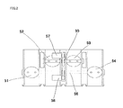
- FIG. 2 is a structural view of the throttle control device according to another embodiment. Here, description on the same structure as that of the above embodiment will be skipped.
- a first throttle valve 51 and a fourth throttle valve 54 being the throttle valves at the outer sides are fixed to an upstream throttle shaft 56. That is, the first throttle shaft and the second throttle shaft are integrated into the upstream side throttle shaft 56. Further, the transmitting portion to transmit operational force of a first motor 58 to the first throttle shaft and the second throttle shaft is integrated into the upstream side throttle shaft 56, as well.
- a second throttle valve 52 and a third throttle valve 53 being the throttle valves at the inner side are fixed to a downstream throttle shaft 55.
- the upstream throttle shaft 56 is rotated by the first motor 58 and the downstream throttle shaft 55 is rotated by a second motor 57.
- the upstream throttle shaft 56 is placed at the upstream side against the downstream throttle shaft 55 in the air-intake direction.
- air-intake amounts of the air-intake passages at the outer sides and the air-intake amounts of the air-intake passages at the inner side are controlled by the separate motors, variation of air-fuel ratio control due to influence of temperature difference and the like between outer side cylinders and inner side cylinders can be suppressed and air-fuel ratio can be stably controlled for each cylinder.
- the present invention effectively functions as a throttle control device to control an air amount to be supplied to an engine having three cylinders or more for a motorcycle and the like.
Landscapes
- Engineering & Computer Science (AREA)
- Chemical & Material Sciences (AREA)
- Combustion & Propulsion (AREA)
- Mechanical Engineering (AREA)
- General Engineering & Computer Science (AREA)
- Control Of Throttle Valves Provided In The Intake System Or In The Exhaust System (AREA)
Abstract
Description
- The present invention relates to a throttle control device in which a motor is driven being based on an operational amount of a throttle grip and the like by a driver and an air-intake amount to an engine is controlled by controlling opening of a throttle valve with the motor.
- In the related art, there has been known a throttle control device in which an operational amount of a throttle grip and the like is detected by an accelerator sensor and throttle valve opening is controlled by driving a motor based on the operational amount (for example, see Japanese Patent Laid-open
2002-256895 - As illustrated in
FIG. 3 , when a throttle valve in the related art is mounted on an engine of a motorcycle, temperature of the vicinity ofthrottle valves throttle valves - Further, in a case that four
exhaust pipes exhaust pipes exhaust pipes throttle valves throttle valves single motor 110, there may be a fear of variation occurrence among air-fuel ratios of the respective cylinders. - To address the above issues, the present invention provides a throttle control device capable of stably controlling air-fuel ratios of respective cylinders even when operational circumstances for inner cylinders are different from those for outer cylinders caused by positional arrangement within a motorcycle.
- A throttle control device of the present invention includes a throttle body having at least three air-intake passages aligned in line as being opened and closed respectively by a throttle valve, plural motors including a first motor which commonly operates the throttle valves placed at bilateral end sides among the throttle valves aligned in line and a second motor which operates a throttle valve placed at the inner side between the throttle valves at the bilateral end sides, and a transmitting portion which transmits operational force of the first motor to a first throttle shaft fixed to one throttle valve of the throttle valves at the bilateral end sides and to a second throttle shaft fixed to the other throttle valve thereof. Here, the first throttle shaft and the second throttle shaft are to be rotated in synchronization with each other owing to the transmitting portion.
- Here, a first throttle gear to which operational force of the first motor is transmitted is fixed to the first throttle shaft and a second throttle gear to which operational force of the first motor is transmitted is fixed to the second throttle shaft. Further, the transmitting portion includes an engaging shaft arranged in parallel to the first throttle shaft and the second throttle shaft, a first engaging gear which is fixed to the engaging shaft as being engaged with the first throttle gear, a second engaging gear which is fixed to the engaging shaft as being engaged with the second throttle gear, and an intermediate gear which is fixed to a midpoint of the engaging shaft as being engaged with an output shaft of the first motor.
- Alternatively, the transmitting portion may be formed as a shaft-shaped member integrated with the first throttle shaft and the second throttle shaft as being arranged at the air-intake upstream side or the air-intake downstream side against a third throttle shaft which is fixed to the throttle valve placed at the inner side.
- According to the throttle control device of the present invention, since air-intake amounts of the air-intake passages at the outer sides and the air-intake amounts of the air-intake passages at the inner side are separately controlled, variation of air-fuel ratio control due to influence of temperature difference and the like between bilateral outer side cylinders and inner side cylinders can be suppressed and air-fuel ratio can be stably controlled for each cylinder.
-
-
FIG. 1 is a structural view of a throttle control device according to an embodiment of the present invention; -
FIG. 2 is a structural view of a throttle control device according to another embodiment of the present invention; and -
FIG. 3 is a structural view of a throttle control device in the related art. - In the following, the structure of a throttle control device according to an embodiment of the present invention will be described with reference to
FIG. 1. FIG. 1 is a perspective view of the throttle control device. - In the throttle control device according to the present embodiment,
throttle bodies intake passages throttle bodies throttle body 7 is placed at the inner side so as to be aligned in the lateral direction of a motorcycle. Thethrottle body 5 at one outer side includes afirst throttle shaft 10 rotatably attached to the inside thereof and afirst throttle valve 14 fixed to thefirst throttle shaft 10 to open and close theintake passage 1. Thethrottle body 6 at the other outer side includes asecond throttle shaft 11 rotatably attached to the inside thereof and afourth throttle valve 17 fixed to thesecond throttle shaft 11 to open and close the intake passage 4. Thethrottle body 7 at the inner side includes athird throttle shaft 12 rotatably attached to the inside thereof and asecond throttle valve 15 and athird throttle valve 16 which are fixed to thethird throttle shaft 12 respectively to open and close theintake passage 2 and theintake passage 3. - Opening of the
first throttle valve 14 and thefourth throttle valve 17 is detected by a firstthrottle opening sensor 18 attached to an end part of thesecond throttle shaft 11 of thethrottle body 16 at the other outer side. Opening of thesecond throttle valve 15 and thethird throttle valve 16 is detected by a secondthrottle opening sensor 19 attached to an end part of thethird throttle shaft 12 of thethrottle body 7 at the inner side. A connector of the secondthrottle opening sensor 19 is oriented in the direction to be apart from a later-mentionedengaging shaft 13. Accordingly, wiring for connector connection can be facilitated. Here, a connector of the firstthrottle opening sensor 18 is oriented toward theengaging shaft 13 side. However, it is also possible to be oriented to the opposite direction. In this case, since the connector of thefirst throttle shaft 18 is to be oriented to the same direction of the connector of the secondthrottle opening sensor 19, wiring with the respective connectors can be simplified. - A
first throttle gear 21 is attached to an end part of thefirst throttle shaft 10 at the one outer side. Asecond throttle gear 22 is attached to an end part of thesecond throttle shaft 11 at the other outer side as being opposite side to the firstthrottle opening sensor 18. Both thefirst throttle gear 21 and thesecond throttle gear 22 are attached as being faced to thethrottle body 7 at the inner side. Thefirst throttle gear 21 and thesecond throttle gear 22 are rotated as being engaged with theengaging shaft 13 having a firstengaging gear 23 and a secondengaging gear 24 at both ends thereof. Theengaging shaft 13 is arranged in parallel to thefirst throttle shaft 10 and thesecond throttle shaft 11. Anintermediate gear 25 is attached at some midpoint of theengaging shaft 13. Theengaging shaft 13 is rotated while rotating theintermediate gear 25 by afirst motor 8. When theengaging shaft 13 is rotated by thefirst motor 8 which is driven being based on a detection value of an accelerator opening sensor (not illustrated), thefirst throttle valve 14 is rotated via the firstengaging gear 23 and thefirst throttle gear 21 and thefourth throttle valve 17 is rotated via the secondengaging gear 24 and thesecond throttle gear 22. Thefirst throttle valve 14 and thefourth throttle valve 17 being the throttle valves placed at the outer sides are rotated as being engaged with theengaging shaft 13 by driving the singlefirst motor 8. Further, since theintermediate gear 25 is attached to the midpoint of theengaging shaft 13 at a position being the center between the firstengaging gear 23 and the secondengaging gear 24, degrees of torsion at both ends of theengaging shaft 13 are evened. Accordingly, thefirst throttle shaft 10 and thesecond throttle shaft 11 being the throttle shafts at the outer sides are reliably synchronized, so that thefirst throttle valve 11 and thefourth throttle valve 17 being the throttle valves at the outer sides can be opened and closed as being reliably synchronized. In this manner, a transmitting portion to transmit operational force of thefirst motor 8 to thefirst throttle shaft 10 and thesecond throttle shaft 11 is constituted with theengaging shaft 13, the firstengaging gear 23, the secondengaging gear 24 and theintermediate gear 25. - Regarding the
throttle body 7 at the inner side, athird throttle gear 27 is attached to one end part of thethird throttle shaft 12 and a secondthrottle opening sensor 19 is attached to the other end part thereof. Thethird throttle gear 27 is interlocked with an output shaft of asecond motor 9 via a thirdengaging gear 20 which is rotated about anintermediate shaft 26. As described above, thesecond throttle valve 15 and thethird throttle valve 16 are fixed to thethird throttle shaft 12. Accordingly, thesecond throttle valve 15 and thethird throttle valve 16 can be opened and closed as being reliably synchronized when thesecond motor 9 is driven being based on a detection value of the accelerator opening sensor (not illustrated). Thefirst motor 8 is arranged at the opposite side to thesecond motor 9 as sandwiching thethird throttle shaft 12. As described above, thethrottle body 7 at the inner side includes the two intake passages having thesecond throttle valve 15 and thethird throttle valve 16. However, there may be a case that only one intake passage with a throttle valve is provided. Further, it is also possible that thefirst motor 8 is arranged at the same side as thesecond motor 9 against thethird throttle shaft 12. In this case, theengaging shaft 13 and theintermediate shaft 26 are arranged so as not to be contacted to each other as being aligned in the air-intake direction at the air-intake passages first motor 8 and thesecond motor 9 are arranged at the same side against the air-intake passages engaging gear 20 is engaged with thethird shaft 12 at some midpoint other than the end part thereof. Furthermore, it is also possible that thethrottle bodies intake passages first throttle valve 14, thesecond throttle valve 15, thethird throttle valve 16 and thefourth throttle valve 17. Here, thethrottle bodies throttle bodies - The
first throttle valve 14 and thefourth throttle valve 17 being the throttle valves at the outer sides are opened and closed by thesingle motor 8. Thesecond throttle valve 15 and thethird throttle valve 16 are opened and closed by the othersingle motor 9. Thus, since air-intake amounts of the air-intake passages 1, 4 at the outer sides and the air-intake amounts of the air-intake passages - Next, the structure of a throttle control device according to another embodiment of the present invention will be described with reference to
FIG. 2. FIG. 2 is a structural view of the throttle control device according to another embodiment. Here, description on the same structure as that of the above embodiment will be skipped. - A
first throttle valve 51 and afourth throttle valve 54 being the throttle valves at the outer sides are fixed to anupstream throttle shaft 56. That is, the first throttle shaft and the second throttle shaft are integrated into the upstreamside throttle shaft 56. Further, the transmitting portion to transmit operational force of afirst motor 58 to the first throttle shaft and the second throttle shaft is integrated into the upstreamside throttle shaft 56, as well. Asecond throttle valve 52 and athird throttle valve 53 being the throttle valves at the inner side are fixed to adownstream throttle shaft 55. Theupstream throttle shaft 56 is rotated by thefirst motor 58 and thedownstream throttle shaft 55 is rotated by asecond motor 57. Theupstream throttle shaft 56 is placed at the upstream side against thedownstream throttle shaft 55 in the air-intake direction. - Thus, since air-intake amounts of the air-intake passages at the outer sides and the air-intake amounts of the air-intake passages at the inner side are controlled by the separate motors, variation of air-fuel ratio control due to influence of temperature difference and the like between outer side cylinders and inner side cylinders can be suppressed and air-fuel ratio can be stably controlled for each cylinder.
- Here, the similar effects can be obtained even when the throttle valves at the outer sides are fixed to the downstream throttle shaft and the throttle valves at the inner side are fixed to the upstream throttle shaft.
- The present invention effectively functions as a throttle control device to control an air amount to be supplied to an engine having three cylinders or more for a motorcycle and the like.
Claims (3)
- A throttle control device to control an air-intake amount for an engine, comprising:a throttle body including at least three air-intake passages aligned in line, each air-intake passage being opened and closed by a throttle valve;a plurality of motors including a first motor which commonly operates the throttle valves placed at bilateral end sides among the throttle valves aligned in line and a second motor which operates a throttle valve placed at the inner side between the throttle valves at the bilateral end sides; anda transmitting portion which transmits operational force of the first motor to a first throttle shaft fixed to one throttle valve of the throttle valves at the bilateral end sides and to a second throttle shaft fixed to the other throttle valve of the throttle valves at the bilateral end sides so as to rotate the first throttle shaft and the second throttle shaft in synchronization with each other.
- The throttle control device according to claim 1,
wherein a first throttle gear to which operational force of the first motor is transmitted is fixed to the first throttle shaft;
a second throttle gear to which operational force of the first motor is transmitted is fixed to the second throttle shaft; and
the transmitting portion includes an engaging shaft arranged in parallel to the first throttle shaft and the second throttle shaft, a first engaging gear which is fixed to the engaging shaft as being engaged with the first throttle gear, a second engaging gear which is fixed to the engaging shaft as being engaged with the second throttle gear, and an intermediate gear which is fixed to a midpoint of the engaging shaft as being engaged with an output shaft of the first motor. - The throttle control device according to claim 1,
wherein the transmitting portion is a shaft-shaped member integrally formed with the first throttle shaft and the second throttle shaft as being arranged at the air-intake upstream side or the air-intake downstream side against a third throttle shaft which is fixed to the throttle valve placed at the inner side.
Applications Claiming Priority (1)
| Application Number | Priority Date | Filing Date | Title |
|---|---|---|---|
| JP2010119932 | 2010-05-25 |
Publications (2)
| Publication Number | Publication Date |
|---|---|
| EP2390487A1 true EP2390487A1 (en) | 2011-11-30 |
| EP2390487B1 EP2390487B1 (en) | 2013-07-10 |
Family
ID=44357926
Family Applications (1)
| Application Number | Title | Priority Date | Filing Date |
|---|---|---|---|
| EP11167449.5A Active EP2390487B1 (en) | 2010-05-25 | 2011-05-25 | Throttle control device |
Country Status (3)
| Country | Link |
|---|---|
| US (1) | US8499741B2 (en) |
| EP (1) | EP2390487B1 (en) |
| JP (1) | JP5854639B2 (en) |
Cited By (6)
| Publication number | Priority date | Publication date | Assignee | Title |
|---|---|---|---|---|
| CN105402031A (en) * | 2015-12-11 | 2016-03-16 | 重庆渝辉机械有限公司 | Low-speed state stably-accelerating throttle valve |
| CN105402035A (en) * | 2015-12-11 | 2016-03-16 | 重庆渝辉机械有限公司 | Double-cylinder engine throttle valve |
| CN105402034A (en) * | 2015-12-11 | 2016-03-16 | 重庆渝辉机械有限公司 | Throttle valve with stepping motor idling for flow adjustment |
| CN105443250A (en) * | 2015-12-11 | 2016-03-30 | 重庆渝辉机械有限公司 | Throttle valve of integrated route circulation system |
| EP3514369A1 (en) * | 2018-01-23 | 2019-07-24 | Mikuni Corporation | Throttle device |
| US10895204B2 (en) | 2018-01-23 | 2021-01-19 | Mikuni Corporation | Throttle device |
Families Citing this family (7)
| Publication number | Priority date | Publication date | Assignee | Title |
|---|---|---|---|---|
| JP6357092B2 (en) * | 2014-12-09 | 2018-07-11 | 川崎重工業株式会社 | Saddle riding |
| JP7131917B2 (en) * | 2018-01-23 | 2022-09-06 | 株式会社ミクニ | Throttle device |
| EP3842734B1 (en) * | 2018-08-23 | 2024-05-08 | Mikuni Corporation | Electronically controlled throttle device for engine |
| WO2020049662A1 (en) * | 2018-09-05 | 2020-03-12 | 本田技研工業株式会社 | General-purpose engine throttle device |
| JP7269262B2 (en) * | 2019-01-10 | 2023-05-08 | 株式会社ミクニ | Electronic control throttle device |
| JP7320605B2 (en) * | 2019-06-14 | 2023-08-03 | 株式会社ミクニ | Throttle device |
| US11448144B1 (en) * | 2021-03-16 | 2022-09-20 | Ford Global Technologies, Llc | Methods and system for controlling an engine with two throttles |
Citations (4)
| Publication number | Priority date | Publication date | Assignee | Title |
|---|---|---|---|---|
| JP2002256895A (en) | 2001-03-05 | 2002-09-11 | Yamaha Motor Co Ltd | Engine throttle control |
| JP2002256896A (en) * | 2001-03-05 | 2002-09-11 | Yamaha Motor Co Ltd | Engine throttle control |
| US20040237934A1 (en) * | 2003-03-27 | 2004-12-02 | Honda Motor Co., Ltd. | Throttle body |
| US20050133004A1 (en) * | 2003-10-06 | 2005-06-23 | Honda Motor Co., Ltd. | Multi-cylinder internal combustion engine |
Family Cites Families (10)
| Publication number | Priority date | Publication date | Assignee | Title |
|---|---|---|---|---|
| JPS5827055Y2 (en) * | 1977-12-13 | 1983-06-11 | トヨタ自動車株式会社 | Intake system of multi-cylinder internal combustion engine |
| JPH03202626A (en) * | 1989-12-29 | 1991-09-04 | Japan Electron Control Syst Co Ltd | Engine cylinder-specific intake control device |
| US7066142B2 (en) * | 2002-09-11 | 2006-06-27 | Mikuni Corporation | Multiple throttle apparatus |
| JP2004132289A (en) * | 2002-10-11 | 2004-04-30 | Mikuni Corp | Multiple throttle device |
| ES2564166T3 (en) * | 2003-11-12 | 2016-03-18 | Yamaha Hatsudoki Kabushiki Kaisha | Electronic butterfly valve and two wheel motor vehicle control system |
| JP4391275B2 (en) * | 2004-03-09 | 2009-12-24 | 三菱電機株式会社 | Multi-cylinder engine operation control device |
| US7237528B2 (en) * | 2004-03-26 | 2007-07-03 | Kawasaki Jukogyo Kabushiki Kaisha | Throttle valve control device for leisure vehicle |
| JP4470748B2 (en) * | 2005-01-27 | 2010-06-02 | トヨタ自動車株式会社 | Intake control device for internal combustion engine |
| JP4799352B2 (en) * | 2006-09-29 | 2011-10-26 | 本田技研工業株式会社 | Electronic throttle control device for V-type internal combustion engine for vehicle |
| JP4760763B2 (en) * | 2007-04-23 | 2011-08-31 | スズキ株式会社 | Electronically controlled throttle valve device |
-
2011
- 2011-05-24 JP JP2011115312A patent/JP5854639B2/en active Active
- 2011-05-25 EP EP11167449.5A patent/EP2390487B1/en active Active
- 2011-05-25 US US13/067,340 patent/US8499741B2/en active Active
Patent Citations (4)
| Publication number | Priority date | Publication date | Assignee | Title |
|---|---|---|---|---|
| JP2002256895A (en) | 2001-03-05 | 2002-09-11 | Yamaha Motor Co Ltd | Engine throttle control |
| JP2002256896A (en) * | 2001-03-05 | 2002-09-11 | Yamaha Motor Co Ltd | Engine throttle control |
| US20040237934A1 (en) * | 2003-03-27 | 2004-12-02 | Honda Motor Co., Ltd. | Throttle body |
| US20050133004A1 (en) * | 2003-10-06 | 2005-06-23 | Honda Motor Co., Ltd. | Multi-cylinder internal combustion engine |
Cited By (6)
| Publication number | Priority date | Publication date | Assignee | Title |
|---|---|---|---|---|
| CN105402031A (en) * | 2015-12-11 | 2016-03-16 | 重庆渝辉机械有限公司 | Low-speed state stably-accelerating throttle valve |
| CN105402035A (en) * | 2015-12-11 | 2016-03-16 | 重庆渝辉机械有限公司 | Double-cylinder engine throttle valve |
| CN105402034A (en) * | 2015-12-11 | 2016-03-16 | 重庆渝辉机械有限公司 | Throttle valve with stepping motor idling for flow adjustment |
| CN105443250A (en) * | 2015-12-11 | 2016-03-30 | 重庆渝辉机械有限公司 | Throttle valve of integrated route circulation system |
| EP3514369A1 (en) * | 2018-01-23 | 2019-07-24 | Mikuni Corporation | Throttle device |
| US10895204B2 (en) | 2018-01-23 | 2021-01-19 | Mikuni Corporation | Throttle device |
Also Published As
| Publication number | Publication date |
|---|---|
| JP5854639B2 (en) | 2016-02-09 |
| EP2390487B1 (en) | 2013-07-10 |
| US20110290213A1 (en) | 2011-12-01 |
| JP2012007608A (en) | 2012-01-12 |
| US8499741B2 (en) | 2013-08-06 |
Similar Documents
| Publication | Publication Date | Title |
|---|---|---|
| EP2390487B1 (en) | Throttle control device | |
| US7055497B2 (en) | Multi-cylinder internal combustion engine | |
| US7610903B2 (en) | Multicylinder internal combustion engine | |
| WO2008149646A1 (en) | Air intake manifold for internal combustion engine | |
| EP1819923B1 (en) | Air-intake device for internal combustion engine | |
| US10060396B2 (en) | Air intake apparatus | |
| US11181048B2 (en) | Throttle device | |
| US7552711B2 (en) | Intake control device for vehicle engine | |
| US9739210B2 (en) | Engine including motorized throttle valve | |
| US9334809B2 (en) | Throttle body structure | |
| US10570778B2 (en) | Coupling system for turbocharger and emission control device | |
| CA2592769A1 (en) | Intake structure of v-type internal combustion engine | |
| CN110778395A (en) | Method and system for variable compression ratio engine | |
| CN110005533A (en) | For using air throttle to carry out the method and system of vacuum generation | |
| CN106687724B (en) | On-off valve structure | |
| US8613271B2 (en) | Engine including intake air flow control assembly | |
| US8336519B2 (en) | Intake system of engine | |
| EP2740917B1 (en) | Throttle device | |
| JP2013241834A (en) | Exhaust gas recirculation device for internal combustion engine | |
| JP2009041478A (en) | Throttle device | |
| JP4470748B2 (en) | Intake control device for internal combustion engine | |
| US10240653B2 (en) | Air intake device | |
| CN101501321A (en) | Variable intake apparatus for internal combustion engine | |
| WO2009041706A3 (en) | Internal combustion engine and vehicle mounted with the same | |
| JP2006194120A (en) | Intake device for internal combustion engine |
Legal Events
| Date | Code | Title | Description |
|---|---|---|---|
| AK | Designated contracting states |
Kind code of ref document: A1 Designated state(s): AL AT BE BG CH CY CZ DE DK EE ES FI FR GB GR HR HU IE IS IT LI LT LU LV MC MK MT NL NO PL PT RO RS SE SI SK SM TR |
|
| AX | Request for extension of the european patent |
Extension state: BA ME |
|
| PUAI | Public reference made under article 153(3) epc to a published international application that has entered the european phase |
Free format text: ORIGINAL CODE: 0009012 |
|
| 17P | Request for examination filed |
Effective date: 20120529 |
|
| GRAP | Despatch of communication of intention to grant a patent |
Free format text: ORIGINAL CODE: EPIDOSNIGR1 |
|
| RIC1 | Information provided on ipc code assigned before grant |
Ipc: F02D 9/10 20060101AFI20130111BHEP |
|
| RIN1 | Information on inventor provided before grant (corrected) |
Inventor name: ISHIKAWA, MICHIHIKO Inventor name: SHINOHARA, HIROYUKI Inventor name: MURASAKA, RIKI |
|
| GRAS | Grant fee paid |
Free format text: ORIGINAL CODE: EPIDOSNIGR3 |
|
| GRAA | (expected) grant |
Free format text: ORIGINAL CODE: 0009210 |
|
| AK | Designated contracting states |
Kind code of ref document: B1 Designated state(s): AL AT BE BG CH CY CZ DE DK EE ES FI FR GB GR HR HU IE IS IT LI LT LU LV MC MK MT NL NO PL PT RO RS SE SI SK SM TR |
|
| REG | Reference to a national code |
Ref country code: GB Ref legal event code: FG4D |
|
| REG | Reference to a national code |
Ref country code: CH Ref legal event code: EP Ref country code: AT Ref legal event code: REF Ref document number: 621112 Country of ref document: AT Kind code of ref document: T Effective date: 20130715 |
|
| REG | Reference to a national code |
Ref country code: IE Ref legal event code: FG4D |
|
| REG | Reference to a national code |
Ref country code: DE Ref legal event code: R096 Ref document number: 602011002256 Country of ref document: DE Effective date: 20130905 |
|
| PG25 | Lapsed in a contracting state [announced via postgrant information from national office to epo] |
Ref country code: SI Free format text: LAPSE BECAUSE OF FAILURE TO SUBMIT A TRANSLATION OF THE DESCRIPTION OR TO PAY THE FEE WITHIN THE PRESCRIBED TIME-LIMIT Effective date: 20130710 |
|
| REG | Reference to a national code |
Ref country code: AT Ref legal event code: MK05 Ref document number: 621112 Country of ref document: AT Kind code of ref document: T Effective date: 20130710 |
|
| REG | Reference to a national code |
Ref country code: NL Ref legal event code: VDEP Effective date: 20130710 |
|
| REG | Reference to a national code |
Ref country code: LT Ref legal event code: MG4D |
|
| PG25 | Lapsed in a contracting state [announced via postgrant information from national office to epo] |
Ref country code: AT Free format text: LAPSE BECAUSE OF FAILURE TO SUBMIT A TRANSLATION OF THE DESCRIPTION OR TO PAY THE FEE WITHIN THE PRESCRIBED TIME-LIMIT Effective date: 20130710 Ref country code: CY Free format text: LAPSE BECAUSE OF FAILURE TO SUBMIT A TRANSLATION OF THE DESCRIPTION OR TO PAY THE FEE WITHIN THE PRESCRIBED TIME-LIMIT Effective date: 20130731 Ref country code: PT Free format text: LAPSE BECAUSE OF FAILURE TO SUBMIT A TRANSLATION OF THE DESCRIPTION OR TO PAY THE FEE WITHIN THE PRESCRIBED TIME-LIMIT Effective date: 20131111 Ref country code: SE Free format text: LAPSE BECAUSE OF FAILURE TO SUBMIT A TRANSLATION OF THE DESCRIPTION OR TO PAY THE FEE WITHIN THE PRESCRIBED TIME-LIMIT Effective date: 20130710 Ref country code: IS Free format text: LAPSE BECAUSE OF FAILURE TO SUBMIT A TRANSLATION OF THE DESCRIPTION OR TO PAY THE FEE WITHIN THE PRESCRIBED TIME-LIMIT Effective date: 20131110 Ref country code: BE Free format text: LAPSE BECAUSE OF FAILURE TO SUBMIT A TRANSLATION OF THE DESCRIPTION OR TO PAY THE FEE WITHIN THE PRESCRIBED TIME-LIMIT Effective date: 20130710 Ref country code: NO Free format text: LAPSE BECAUSE OF FAILURE TO SUBMIT A TRANSLATION OF THE DESCRIPTION OR TO PAY THE FEE WITHIN THE PRESCRIBED TIME-LIMIT Effective date: 20131010 Ref country code: LT Free format text: LAPSE BECAUSE OF FAILURE TO SUBMIT A TRANSLATION OF THE DESCRIPTION OR TO PAY THE FEE WITHIN THE PRESCRIBED TIME-LIMIT Effective date: 20130710 Ref country code: HR Free format text: LAPSE BECAUSE OF FAILURE TO SUBMIT A TRANSLATION OF THE DESCRIPTION OR TO PAY THE FEE WITHIN THE PRESCRIBED TIME-LIMIT Effective date: 20130710 |
|
| PG25 | Lapsed in a contracting state [announced via postgrant information from national office to epo] |
Ref country code: GR Free format text: LAPSE BECAUSE OF FAILURE TO SUBMIT A TRANSLATION OF THE DESCRIPTION OR TO PAY THE FEE WITHIN THE PRESCRIBED TIME-LIMIT Effective date: 20131011 Ref country code: ES Free format text: LAPSE BECAUSE OF FAILURE TO SUBMIT A TRANSLATION OF THE DESCRIPTION OR TO PAY THE FEE WITHIN THE PRESCRIBED TIME-LIMIT Effective date: 20131021 Ref country code: NL Free format text: LAPSE BECAUSE OF FAILURE TO SUBMIT A TRANSLATION OF THE DESCRIPTION OR TO PAY THE FEE WITHIN THE PRESCRIBED TIME-LIMIT Effective date: 20130710 Ref country code: PL Free format text: LAPSE BECAUSE OF FAILURE TO SUBMIT A TRANSLATION OF THE DESCRIPTION OR TO PAY THE FEE WITHIN THE PRESCRIBED TIME-LIMIT Effective date: 20130710 Ref country code: FI Free format text: LAPSE BECAUSE OF FAILURE TO SUBMIT A TRANSLATION OF THE DESCRIPTION OR TO PAY THE FEE WITHIN THE PRESCRIBED TIME-LIMIT Effective date: 20130710 Ref country code: LV Free format text: LAPSE BECAUSE OF FAILURE TO SUBMIT A TRANSLATION OF THE DESCRIPTION OR TO PAY THE FEE WITHIN THE PRESCRIBED TIME-LIMIT Effective date: 20130710 |
|
| PG25 | Lapsed in a contracting state [announced via postgrant information from national office to epo] |
Ref country code: CY Free format text: LAPSE BECAUSE OF FAILURE TO SUBMIT A TRANSLATION OF THE DESCRIPTION OR TO PAY THE FEE WITHIN THE PRESCRIBED TIME-LIMIT Effective date: 20130710 |
|
| PG25 | Lapsed in a contracting state [announced via postgrant information from national office to epo] |
Ref country code: EE Free format text: LAPSE BECAUSE OF FAILURE TO SUBMIT A TRANSLATION OF THE DESCRIPTION OR TO PAY THE FEE WITHIN THE PRESCRIBED TIME-LIMIT Effective date: 20130710 Ref country code: CZ Free format text: LAPSE BECAUSE OF FAILURE TO SUBMIT A TRANSLATION OF THE DESCRIPTION OR TO PAY THE FEE WITHIN THE PRESCRIBED TIME-LIMIT Effective date: 20130710 Ref country code: RO Free format text: LAPSE BECAUSE OF FAILURE TO SUBMIT A TRANSLATION OF THE DESCRIPTION OR TO PAY THE FEE WITHIN THE PRESCRIBED TIME-LIMIT Effective date: 20130710 Ref country code: SK Free format text: LAPSE BECAUSE OF FAILURE TO SUBMIT A TRANSLATION OF THE DESCRIPTION OR TO PAY THE FEE WITHIN THE PRESCRIBED TIME-LIMIT Effective date: 20130710 Ref country code: DK Free format text: LAPSE BECAUSE OF FAILURE TO SUBMIT A TRANSLATION OF THE DESCRIPTION OR TO PAY THE FEE WITHIN THE PRESCRIBED TIME-LIMIT Effective date: 20130710 |
|
| PLBE | No opposition filed within time limit |
Free format text: ORIGINAL CODE: 0009261 |
|
| STAA | Information on the status of an ep patent application or granted ep patent |
Free format text: STATUS: NO OPPOSITION FILED WITHIN TIME LIMIT |
|
| 26N | No opposition filed |
Effective date: 20140411 |
|
| REG | Reference to a national code |
Ref country code: DE Ref legal event code: R097 Ref document number: 602011002256 Country of ref document: DE Effective date: 20140411 |
|
| PG25 | Lapsed in a contracting state [announced via postgrant information from national office to epo] |
Ref country code: LU Free format text: LAPSE BECAUSE OF FAILURE TO SUBMIT A TRANSLATION OF THE DESCRIPTION OR TO PAY THE FEE WITHIN THE PRESCRIBED TIME-LIMIT Effective date: 20140525 |
|
| REG | Reference to a national code |
Ref country code: CH Ref legal event code: PL |
|
| PG25 | Lapsed in a contracting state [announced via postgrant information from national office to epo] |
Ref country code: MC Free format text: LAPSE BECAUSE OF FAILURE TO SUBMIT A TRANSLATION OF THE DESCRIPTION OR TO PAY THE FEE WITHIN THE PRESCRIBED TIME-LIMIT Effective date: 20130710 Ref country code: LI Free format text: LAPSE BECAUSE OF NON-PAYMENT OF DUE FEES Effective date: 20140531 Ref country code: CH Free format text: LAPSE BECAUSE OF NON-PAYMENT OF DUE FEES Effective date: 20140531 |
|
| REG | Reference to a national code |
Ref country code: IE Ref legal event code: MM4A |
|
| REG | Reference to a national code |
Ref country code: FR Ref legal event code: ST Effective date: 20150130 |
|
| PG25 | Lapsed in a contracting state [announced via postgrant information from national office to epo] |
Ref country code: IE Free format text: LAPSE BECAUSE OF NON-PAYMENT OF DUE FEES Effective date: 20140525 |
|
| PG25 | Lapsed in a contracting state [announced via postgrant information from national office to epo] |
Ref country code: FR Free format text: LAPSE BECAUSE OF NON-PAYMENT OF DUE FEES Effective date: 20140602 |
|
| GBPC | Gb: european patent ceased through non-payment of renewal fee |
Effective date: 20150525 |
|
| PG25 | Lapsed in a contracting state [announced via postgrant information from national office to epo] |
Ref country code: MT Free format text: LAPSE BECAUSE OF FAILURE TO SUBMIT A TRANSLATION OF THE DESCRIPTION OR TO PAY THE FEE WITHIN THE PRESCRIBED TIME-LIMIT Effective date: 20130710 |
|
| PG25 | Lapsed in a contracting state [announced via postgrant information from national office to epo] |
Ref country code: SM Free format text: LAPSE BECAUSE OF FAILURE TO SUBMIT A TRANSLATION OF THE DESCRIPTION OR TO PAY THE FEE WITHIN THE PRESCRIBED TIME-LIMIT Effective date: 20130710 Ref country code: GB Free format text: LAPSE BECAUSE OF NON-PAYMENT OF DUE FEES Effective date: 20150525 |
|
| PG25 | Lapsed in a contracting state [announced via postgrant information from national office to epo] |
Ref country code: RS Free format text: LAPSE BECAUSE OF FAILURE TO SUBMIT A TRANSLATION OF THE DESCRIPTION OR TO PAY THE FEE WITHIN THE PRESCRIBED TIME-LIMIT Effective date: 20130710 Ref country code: BG Free format text: LAPSE BECAUSE OF FAILURE TO SUBMIT A TRANSLATION OF THE DESCRIPTION OR TO PAY THE FEE WITHIN THE PRESCRIBED TIME-LIMIT Effective date: 20130710 |
|
| PG25 | Lapsed in a contracting state [announced via postgrant information from national office to epo] |
Ref country code: TR Free format text: LAPSE BECAUSE OF FAILURE TO SUBMIT A TRANSLATION OF THE DESCRIPTION OR TO PAY THE FEE WITHIN THE PRESCRIBED TIME-LIMIT Effective date: 20130710 Ref country code: HU Free format text: LAPSE BECAUSE OF FAILURE TO SUBMIT A TRANSLATION OF THE DESCRIPTION OR TO PAY THE FEE WITHIN THE PRESCRIBED TIME-LIMIT; INVALID AB INITIO Effective date: 20110525 |
|
| PG25 | Lapsed in a contracting state [announced via postgrant information from national office to epo] |
Ref country code: MK Free format text: LAPSE BECAUSE OF FAILURE TO SUBMIT A TRANSLATION OF THE DESCRIPTION OR TO PAY THE FEE WITHIN THE PRESCRIBED TIME-LIMIT Effective date: 20130710 |
|
| PG25 | Lapsed in a contracting state [announced via postgrant information from national office to epo] |
Ref country code: AL Free format text: LAPSE BECAUSE OF FAILURE TO SUBMIT A TRANSLATION OF THE DESCRIPTION OR TO PAY THE FEE WITHIN THE PRESCRIBED TIME-LIMIT Effective date: 20130710 |
|
| PGFP | Annual fee paid to national office [announced via postgrant information from national office to epo] |
Ref country code: DE Payment date: 20250402 Year of fee payment: 15 |
|
| PGFP | Annual fee paid to national office [announced via postgrant information from national office to epo] |
Ref country code: IT Payment date: 20250422 Year of fee payment: 15 |