US8613271B2 - Engine including intake air flow control assembly - Google Patents
Engine including intake air flow control assembly Download PDFInfo
- Publication number
- US8613271B2 US8613271B2 US13/204,136 US201113204136A US8613271B2 US 8613271 B2 US8613271 B2 US 8613271B2 US 201113204136 A US201113204136 A US 201113204136A US 8613271 B2 US8613271 B2 US 8613271B2
- Authority
- US
- United States
- Prior art keywords
- valve
- shaft
- air flow
- valve shaft
- drive
- Prior art date
- Legal status (The legal status is an assumption and is not a legal conclusion. Google has not performed a legal analysis and makes no representation as to the accuracy of the status listed.)
- Expired - Fee Related, expires
Links
Images


Classifications
-
- F—MECHANICAL ENGINEERING; LIGHTING; HEATING; WEAPONS; BLASTING
- F02—COMBUSTION ENGINES; HOT-GAS OR COMBUSTION-PRODUCT ENGINE PLANTS
- F02B—INTERNAL-COMBUSTION PISTON ENGINES; COMBUSTION ENGINES IN GENERAL
- F02B31/00—Modifying induction systems for imparting a rotation to the charge in the cylinder
- F02B31/08—Modifying induction systems for imparting a rotation to the charge in the cylinder having multiple air inlets
- F02B31/085—Modifying induction systems for imparting a rotation to the charge in the cylinder having multiple air inlets having two inlet valves
-
- F—MECHANICAL ENGINEERING; LIGHTING; HEATING; WEAPONS; BLASTING
- F02—COMBUSTION ENGINES; HOT-GAS OR COMBUSTION-PRODUCT ENGINE PLANTS
- F02D—CONTROLLING COMBUSTION ENGINES
- F02D9/00—Controlling engines by throttling air or fuel-and-air induction conduits or exhaust conduits
- F02D9/08—Throttle valves specially adapted therefor; Arrangements of such valves in conduits
- F02D9/10—Throttle valves specially adapted therefor; Arrangements of such valves in conduits having pivotally-mounted flaps
- F02D9/1065—Mechanical control linkage between an actuator and the flap, e.g. including levers, gears, springs, clutches, limit stops of the like
-
- F—MECHANICAL ENGINEERING; LIGHTING; HEATING; WEAPONS; BLASTING
- F02—COMBUSTION ENGINES; HOT-GAS OR COMBUSTION-PRODUCT ENGINE PLANTS
- F02D—CONTROLLING COMBUSTION ENGINES
- F02D9/00—Controlling engines by throttling air or fuel-and-air induction conduits or exhaust conduits
- F02D9/08—Throttle valves specially adapted therefor; Arrangements of such valves in conduits
- F02D9/10—Throttle valves specially adapted therefor; Arrangements of such valves in conduits having pivotally-mounted flaps
- F02D9/109—Throttle valves specially adapted therefor; Arrangements of such valves in conduits having pivotally-mounted flaps having two or more flaps
- F02D9/1095—Rotating on a common axis, e.g. having a common shaft
-
- F—MECHANICAL ENGINEERING; LIGHTING; HEATING; WEAPONS; BLASTING
- F02—COMBUSTION ENGINES; HOT-GAS OR COMBUSTION-PRODUCT ENGINE PLANTS
- F02D—CONTROLLING COMBUSTION ENGINES
- F02D9/00—Controlling engines by throttling air or fuel-and-air induction conduits or exhaust conduits
- F02D9/02—Controlling engines by throttling air or fuel-and-air induction conduits or exhaust conduits concerning induction conduits
- F02D2009/0201—Arrangements; Control features; Details thereof
- F02D2009/0261—Arrangements; Control features; Details thereof having a specially shaped transmission member, e.g. a cam, specially toothed gears, with a clutch
-
- Y—GENERAL TAGGING OF NEW TECHNOLOGICAL DEVELOPMENTS; GENERAL TAGGING OF CROSS-SECTIONAL TECHNOLOGIES SPANNING OVER SEVERAL SECTIONS OF THE IPC; TECHNICAL SUBJECTS COVERED BY FORMER USPC CROSS-REFERENCE ART COLLECTIONS [XRACs] AND DIGESTS
- Y02—TECHNOLOGIES OR APPLICATIONS FOR MITIGATION OR ADAPTATION AGAINST CLIMATE CHANGE
- Y02T—CLIMATE CHANGE MITIGATION TECHNOLOGIES RELATED TO TRANSPORTATION
- Y02T10/00—Road transport of goods or passengers
- Y02T10/10—Internal combustion engine [ICE] based vehicles
- Y02T10/12—Improving ICE efficiencies
Definitions
- the present disclosure relates to engine air flow control assemblies.
- Internal combustion engines may combust a mixture of air and fuel in cylinders and thereby produce drive torque.
- Air and fuel flow into and out of the cylinders may be controlled by a valvetrain. Controlling air flow into the cylinders to generate swirl or tumble flow may enhance combustion at some operating conditions. Swirl and/or tumble flow may be generated by providing an obstruction in the intake air flow path.
- An engine assembly may include an engine structure, an intake manifold, an intake valve and an intake air flow control assembly.
- the engine structure may define a cylinder and an intake port in communication with the cylinder.
- the intake manifold may be in communication with an air source and the intake port.
- the intake valve may be supported on the engine structure and may control communication between the intake port and the cylinder.
- the intake air flow control assembly may include an actuator, a valve shaft, a first valve member and a drive member.
- the actuator may include a drive shaft defining a first rotational axis.
- the valve shaft may define a second rotational axis.
- the first valve member may be fixed for rotation with the valve shaft and adapted to adjust air flow from the intake manifold to the intake port.
- the drive member may be engaged with the drive shaft and the valve shaft.
- the drive member may extend around an outer circumference of the drive shaft and around an outer circumference of the valve shaft.
- the drive shaft may be rotatable in first and second rotational directions opposite one another to rotate the valve shaft via the drive member and rotationally displace the first valve member to adjust air flow from the intake manifold to the intake port.
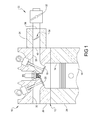
- FIG. 1 is a schematic section view of an engine assembly according to the present disclosure
- FIG. 2 is a perspective view of an intake manifold and an intake air flow control assembly from the engine assembly shown in FIG. 1 ;
- FIG. 3 is a perspective view of the intake air flow control assembly shown in FIG. 2 ;
- FIG. 4 is a schematic illustration of the drive arrangement from the intake air flow control assembly shown in FIGS. 2 and 3 ;
- FIG. 5 is an additional schematic illustration of the drive arrangement from the intake air flow control assembly shown in FIGS. 2 and 3 .
- Example embodiments are provided so that this disclosure will be thorough, and will fully convey the scope to those who are skilled in the art. Numerous specific details are set forth such as examples of specific components, devices, and methods, to provide a thorough understanding of embodiments of the present disclosure. It will be apparent to those skilled in the art that specific details need not be employed, that example embodiments may be embodied in many different forms and that neither should be construed to limit the scope of the disclosure. In some example embodiments, well-known processes, well-known device structures, and well-known technologies are not described in detail.
- first, second, third, etc. may be used herein to describe various elements, components, regions, layers and/or sections, these elements, components, regions, layers and/or sections should not be limited by these terms. These terms may be only used to distinguish one element, component, region, layer or section from another region, layer or section. Terms such as “first,” “second,” and other numerical terms when used herein do not imply a sequence or order unless clearly indicated by the context. Thus, a first element, component, region, layer or section discussed below could be termed a second element, component, region, layer or section without departing from the teachings of the example embodiments.
- the engine assembly 10 may include an engine structure 12 defining cylinders 14 , pistons 16 disposed within the cylinders 14 , intake and exhaust valves 18 , 20 and an intake assembly 22 .
- the engine structure 12 may include an engine block 24 defining the cylinders 14 and a cylinder head 26 coupled to the engine block 24 .
- the cylinder head 26 may define intake and exhaust ports 28 , 30 .
- the intake valve 18 may be located in the intake port 28 and may control air flow into the cylinder 14 and the exhaust valve 20 may be located in the exhaust port 30 and may control exhaust gas flow from the cylinder 14 .
- the intake assembly 22 may include a throttle valve 32 , an intake manifold 34 and an intake air flow control assembly 36 .
- the intake manifold 34 may define an inlet 38 in communication with the throttle valve 32 and outlets 40 in communication with the intake ports 28 .
- the intake air flow control assembly 36 may include an actuator 42 , a mixture motion control valve 44 , and a drive member 46 .
- the actuator 42 may include a motor 48 and a drive shaft 50 rotationally driven by the motor 48 .
- the mixture motion control valve 44 may include a valve shaft 52 , valve members 54 , and a drive hub 56 .
- the valve members 54 and the drive hub 56 may be fixed for rotation with the valve shaft 52 .
- the mixture motion control valve 44 includes four valve members 54 spaced axially from one another along the length of the valve shaft 52 .
- the valve members 54 may be located in the intake air flow path from the throttle valve 32 and the intake valves 18 .
- the valve members 54 may be located in the outlets 40 of the intake manifold 34 with the valve shaft intersecting and extending through the intake manifold 34 at the outlets 40 .
- the drive hub 56 may be a separate member fixed to the valve shaft 52 or may be an integrally formed region of the valve shaft 52 .
- the drive member 46 may be engaged with the drive shaft 50 and the valve shaft 52 . More specifically, the drive member 46 may extend around an outer circumference of the drive shaft 50 and around an outer circumference of the valve shaft 52 . In the present non-limiting example, the drive member 46 is fixed for rotation with the drive shaft 50 and the valve shaft 52 .
- the drive member 46 may include a cable and may be fixed to the drive shaft 50 by a first fastener 58 and may be fixed to the valve shaft 52 by a second fastener 60 .
- the first fastener 58 may include a screw engaged with the drive shaft 50 and a washer 62 located between a head 64 of the screw and the drive shaft 50 .
- the washer 62 may clamp the drive member 46 against the drive shaft 50 .
- the second fastener 60 may include a screw engaged with the drive hub 56 of the valve shaft 52 .
- a washer 66 may be located between a head 68 of the screw and the drive hub 56 , clamping the drive member 46 against the drive hub 56 .
- the drive shaft 50 may define a first rotational axis (A 1 ) and the valve shaft 52 may define a second rotational axis (A 2 ).
- the first and second rotational axes (A 1 , A 2 ) may be parallel to one another and the drive member 46 may extend around the first and second rotational axes (A 1 , A 2 ).
- the motor 48 may power rotation of the drive shaft 50 about the first rotational axis (A 1 ), driving rotation of the valve shaft 52 and valve members 54 about the second rotational axis (A 2 ) to adjust air flow from the intake manifold 34 to the intake ports 28 .
- the drive shaft 50 may be rotatable in first and second rotational directions opposite one another to drive rotation of the valve shaft 52 and valve members 54 . Rotation of the drive shaft 50 in the first rotational direction may provide rotation of the valve shaft 52 and valve members 54 in the first rotational direction. Similarly, rotation of the drive shaft 50 in the second rotational direction may provide rotation of the valve shaft 52 and valve members 54 in the second rotational direction.
- the drive shaft 50 may define a first radius (R 1 ) perpendicular to the first rotational axis (A 1 ).
- the valve shaft 52 may define a second radius (R 2 ) at the drive hub 56 .
- the second radius (R 2 ) may be perpendicular to the second rotational axis (A 2 ).
- the first radius (R 1 ) may form a first moment arm during actuation of the intake air flow control assembly 36 and the second radius (R 2 ) may form a second moment arm during actuation of the intake air flow control assembly 36 .
- the first and second moment arms may be constant throughout actuation of the intake air flow control assembly 36 . Therefore, the load on the motor 48 during actuation of the intake air flow control assembly 36 may be reduced relative to conventional linkage arrangements where the effective moment arm length varies throughout actuation due to displacement of the linkages relative to one another.
Landscapes
- Engineering & Computer Science (AREA)
- Chemical & Material Sciences (AREA)
- Combustion & Propulsion (AREA)
- Mechanical Engineering (AREA)
- General Engineering & Computer Science (AREA)
- Control Of Throttle Valves Provided In The Intake System Or In The Exhaust System (AREA)
- Lift Valve (AREA)
Abstract
Description
Claims (16)
Priority Applications (3)
| Application Number | Priority Date | Filing Date | Title |
|---|---|---|---|
| US13/204,136 US8613271B2 (en) | 2011-08-05 | 2011-08-05 | Engine including intake air flow control assembly |
| DE102012213571.5A DE102012213571B4 (en) | 2011-08-05 | 2012-08-01 | MACHINE ASSEMBLY FOR AIR FLOW CONTROL |
| CN201210274920.3A CN102913330B (en) | 2011-08-05 | 2012-08-03 | The electromotor of assembly is controlled including inlet air flow |
Applications Claiming Priority (1)
| Application Number | Priority Date | Filing Date | Title |
|---|---|---|---|
| US13/204,136 US8613271B2 (en) | 2011-08-05 | 2011-08-05 | Engine including intake air flow control assembly |
Publications (2)
| Publication Number | Publication Date |
|---|---|
| US20130032122A1 US20130032122A1 (en) | 2013-02-07 |
| US8613271B2 true US8613271B2 (en) | 2013-12-24 |
Family
ID=47554344
Family Applications (1)
| Application Number | Title | Priority Date | Filing Date |
|---|---|---|---|
| US13/204,136 Expired - Fee Related US8613271B2 (en) | 2011-08-05 | 2011-08-05 | Engine including intake air flow control assembly |
Country Status (3)
| Country | Link |
|---|---|
| US (1) | US8613271B2 (en) |
| CN (1) | CN102913330B (en) |
| DE (1) | DE102012213571B4 (en) |
Cited By (2)
| Publication number | Priority date | Publication date | Assignee | Title |
|---|---|---|---|---|
| US9927006B2 (en) | 2015-09-01 | 2018-03-27 | Achates Power, Inc. | Multi-speed planetary drive for a supercharger |
| US12012920B2 (en) | 2019-05-03 | 2024-06-18 | Walbro Llc | Charge forming device with throttle valve |
Citations (3)
| Publication number | Priority date | Publication date | Assignee | Title |
|---|---|---|---|---|
| US4840349A (en) * | 1987-11-21 | 1989-06-20 | Robert Bosch Gmbh | Device for actuating a throttle valve |
| US5325829A (en) * | 1992-09-25 | 1994-07-05 | Schmelzer Corporation | Intake manifold air inlet control actuator |
| US7140349B2 (en) * | 2002-10-11 | 2006-11-28 | Mikuni Corporation | Multiple throttle device |
Family Cites Families (8)
| Publication number | Priority date | Publication date | Assignee | Title |
|---|---|---|---|---|
| JPS5828569A (en) * | 1981-08-13 | 1983-02-19 | Toyota Motor Corp | Engine speed control unit |
| JP3437604B2 (en) | 1993-06-16 | 2003-08-18 | 日本ケーブル・システム株式会社 | Accelerator actuator system |
| US7814748B2 (en) | 2006-05-05 | 2010-10-19 | Continental Automotive Canada, Inc. | Exhaust bypass valve remote linkage |
| DE102008030005A1 (en) | 2008-06-24 | 2009-12-31 | Mahle International Gmbh | actuator |
| DE102008046594A1 (en) | 2008-07-18 | 2010-01-21 | Mahle International Gmbh | valve means |
| DE102008036494A1 (en) | 2008-08-05 | 2010-02-11 | Mahle International Gmbh | Stationary loaded four-stroke internal-combustion engine i.e. diesel engine, operating method for commercial motor vehicle, involves actuating auxiliary valves during operation of engine such that auxiliary valves close paths |
| KR101145630B1 (en) | 2009-12-03 | 2012-05-16 | 기아자동차주식회사 | Intake system of engine |
| CN101975127A (en) * | 2010-11-18 | 2011-02-16 | 重庆隆鑫机车有限公司 | Air intake system capable of automatically adjusting air flow and motorcycle thereof |
-
2011
- 2011-08-05 US US13/204,136 patent/US8613271B2/en not_active Expired - Fee Related
-
2012
- 2012-08-01 DE DE102012213571.5A patent/DE102012213571B4/en not_active Expired - Fee Related
- 2012-08-03 CN CN201210274920.3A patent/CN102913330B/en not_active Expired - Fee Related
Patent Citations (3)
| Publication number | Priority date | Publication date | Assignee | Title |
|---|---|---|---|---|
| US4840349A (en) * | 1987-11-21 | 1989-06-20 | Robert Bosch Gmbh | Device for actuating a throttle valve |
| US5325829A (en) * | 1992-09-25 | 1994-07-05 | Schmelzer Corporation | Intake manifold air inlet control actuator |
| US7140349B2 (en) * | 2002-10-11 | 2006-11-28 | Mikuni Corporation | Multiple throttle device |
Cited By (3)
| Publication number | Priority date | Publication date | Assignee | Title |
|---|---|---|---|---|
| US9927006B2 (en) | 2015-09-01 | 2018-03-27 | Achates Power, Inc. | Multi-speed planetary drive for a supercharger |
| US12012920B2 (en) | 2019-05-03 | 2024-06-18 | Walbro Llc | Charge forming device with throttle valve |
| US12385457B2 (en) | 2019-05-03 | 2025-08-12 | Walbro Llc | Method of controlling a fuel injector |
Also Published As
| Publication number | Publication date |
|---|---|
| CN102913330A (en) | 2013-02-06 |
| CN102913330B (en) | 2016-07-06 |
| DE102012213571A1 (en) | 2013-02-07 |
| US20130032122A1 (en) | 2013-02-07 |
| DE102012213571B4 (en) | 2019-10-24 |
Similar Documents
| Publication | Publication Date | Title |
|---|---|---|
| JP4706775B2 (en) | Intake device for internal combustion engine | |
| US20110162611A1 (en) | Engine intake air flow control assembly | |
| US20080035094A1 (en) | Integrated valve device | |
| US8683965B2 (en) | Engine assembly including camshaft actuator | |
| US8627659B2 (en) | Engine assembly including exhaust port separation for turbine feed | |
| US9051871B1 (en) | Variable twin-scroll turbine for turbocharged internal combustion engine featuring cylinder deactivation | |
| CN104919169B (en) | Intake Control System for Multi-cylinder Internal Combustion Engine | |
| US8069837B2 (en) | Intake control device for internal combustion engine | |
| JP4434269B2 (en) | Intake control device for internal combustion engine | |
| US8613271B2 (en) | Engine including intake air flow control assembly | |
| JP2004526901A5 (en) | ||
| JP4449750B2 (en) | Intake device for internal combustion engine | |
| US9784220B2 (en) | Intake air control apparatus of engine | |
| JP5742538B2 (en) | Exhaust device for internal combustion engine | |
| US11408331B2 (en) | Wastegate assembly and turbocharger including the same | |
| JP5828517B2 (en) | Intake control device for multi-cylinder engine | |
| US8336519B2 (en) | Intake system of engine | |
| JP2010121552A (en) | Intake device for internal combustion engine | |
| JP2008095924A (en) | Sealing device | |
| KR101476694B1 (en) | Engine Intake Apparatus and Production Method thereof | |
| EP3321487B1 (en) | Rotary electromechanical actuator for powertrain applications, in particular for a turbocharger adjusting system | |
| US8650874B2 (en) | Engine assembly including intake boost system | |
| JP5610217B2 (en) | Intake device for internal combustion engine | |
| JP2006194120A (en) | Intake device for internal combustion engine | |
| WO2023095266A1 (en) | Flow path switch valve |
Legal Events
| Date | Code | Title | Description |
|---|---|---|---|
| AS | Assignment |
Owner name: GM GLOBAL TECHNOLOGY OPERATIONS LLC, MICHIGAN Free format text: ASSIGNMENT OF ASSIGNORS INTEREST;ASSIGNORS:DENG, DINGFENG;SHI, FANGHUI;LIU, YUCHUAN;AND OTHERS;REEL/FRAME:026709/0328 Effective date: 20110803 |
|
| AS | Assignment |
Owner name: WILMINGTON TRUST COMPANY, DELAWARE Free format text: SECURITY AGREEMENT;ASSIGNOR:GM GLOBAL TECHNOLOGY OPERATIONS LLC;REEL/FRAME:028466/0870 Effective date: 20101027 |
|
| FEPP | Fee payment procedure |
Free format text: PAYOR NUMBER ASSIGNED (ORIGINAL EVENT CODE: ASPN); ENTITY STATUS OF PATENT OWNER: LARGE ENTITY |
|
| STCF | Information on status: patent grant |
Free format text: PATENTED CASE |
|
| AS | Assignment |
Owner name: GM GLOBAL TECHNOLOGY OPERATIONS LLC, MICHIGAN Free format text: RELEASE BY SECURED PARTY;ASSIGNOR:WILMINGTON TRUST COMPANY;REEL/FRAME:034186/0776 Effective date: 20141017 |
|
| FPAY | Fee payment |
Year of fee payment: 4 |
|
| FEPP | Fee payment procedure |
Free format text: MAINTENANCE FEE REMINDER MAILED (ORIGINAL EVENT CODE: REM.); ENTITY STATUS OF PATENT OWNER: LARGE ENTITY |
|
| LAPS | Lapse for failure to pay maintenance fees |
Free format text: PATENT EXPIRED FOR FAILURE TO PAY MAINTENANCE FEES (ORIGINAL EVENT CODE: EXP.); ENTITY STATUS OF PATENT OWNER: LARGE ENTITY |
|
| STCH | Information on status: patent discontinuation |
Free format text: PATENT EXPIRED DUE TO NONPAYMENT OF MAINTENANCE FEES UNDER 37 CFR 1.362 |
|
| FP | Lapsed due to failure to pay maintenance fee |
Effective date: 20211224 |