JP4799352B2 - Electronic throttle control device for V-type internal combustion engine for vehicle - Google Patents
Electronic throttle control device for V-type internal combustion engine for vehicle Download PDFInfo
- Publication number
- JP4799352B2 JP4799352B2 JP2006270000A JP2006270000A JP4799352B2 JP 4799352 B2 JP4799352 B2 JP 4799352B2 JP 2006270000 A JP2006270000 A JP 2006270000A JP 2006270000 A JP2006270000 A JP 2006270000A JP 4799352 B2 JP4799352 B2 JP 4799352B2
- Authority
- JP
- Japan
- Prior art keywords
- throttle
- throttle valve
- combustion engine
- internal combustion
- valve
- Prior art date
- Legal status (The legal status is an assumption and is not a legal conclusion. Google has not performed a legal analysis and makes no representation as to the accuracy of the status listed.)
- Active
Links
Images


Classifications
-
- F—MECHANICAL ENGINEERING; LIGHTING; HEATING; WEAPONS; BLASTING
- F02—COMBUSTION ENGINES; HOT-GAS OR COMBUSTION-PRODUCT ENGINE PLANTS
- F02D—CONTROLLING COMBUSTION ENGINES
- F02D9/00—Controlling engines by throttling air or fuel-and-air induction conduits or exhaust conduits
- F02D9/08—Throttle valves specially adapted therefor; Arrangements of such valves in conduits
- F02D9/10—Throttle valves specially adapted therefor; Arrangements of such valves in conduits having pivotally-mounted flaps
- F02D9/109—Throttle valves specially adapted therefor; Arrangements of such valves in conduits having pivotally-mounted flaps having two or more flaps
- F02D9/1095—Rotating on a common axis, e.g. having a common shaft
-
- F—MECHANICAL ENGINEERING; LIGHTING; HEATING; WEAPONS; BLASTING
- F02—COMBUSTION ENGINES; HOT-GAS OR COMBUSTION-PRODUCT ENGINE PLANTS
- F02D—CONTROLLING COMBUSTION ENGINES
- F02D11/00—Arrangements for, or adaptations to, non-automatic engine control initiation means, e.g. operator initiated
- F02D11/06—Arrangements for, or adaptations to, non-automatic engine control initiation means, e.g. operator initiated characterised by non-mechanical control linkages, e.g. fluid control linkages or by control linkages with power drive or assistance
- F02D11/10—Arrangements for, or adaptations to, non-automatic engine control initiation means, e.g. operator initiated characterised by non-mechanical control linkages, e.g. fluid control linkages or by control linkages with power drive or assistance of the electric type
-
- F—MECHANICAL ENGINEERING; LIGHTING; HEATING; WEAPONS; BLASTING
- F02—COMBUSTION ENGINES; HOT-GAS OR COMBUSTION-PRODUCT ENGINE PLANTS
- F02D—CONTROLLING COMBUSTION ENGINES
- F02D9/00—Controlling engines by throttling air or fuel-and-air induction conduits or exhaust conduits
- F02D9/08—Throttle valves specially adapted therefor; Arrangements of such valves in conduits
- F02D9/10—Throttle valves specially adapted therefor; Arrangements of such valves in conduits having pivotally-mounted flaps
- F02D9/107—Manufacturing or mounting details
-
- F—MECHANICAL ENGINEERING; LIGHTING; HEATING; WEAPONS; BLASTING
- F02—COMBUSTION ENGINES; HOT-GAS OR COMBUSTION-PRODUCT ENGINE PLANTS
- F02M—SUPPLYING COMBUSTION ENGINES IN GENERAL WITH COMBUSTIBLE MIXTURES OR CONSTITUENTS THEREOF
- F02M35/00—Combustion-air cleaners, air intakes, intake silencers, or induction systems specially adapted for, or arranged on, internal-combustion engines
- F02M35/10—Air intakes; Induction systems
- F02M35/10006—Air intakes; Induction systems characterised by the position of elements of the air intake system in direction of the air intake flow, i.e. between ambient air inlet and supply to the combustion chamber
- F02M35/10026—Plenum chambers
- F02M35/10032—Plenum chambers specially shaped or arranged connecting duct between carburettor or air inlet duct and the plenum chamber; specially positioned carburettors or throttle bodies with respect to the plenum chamber
-
- F—MECHANICAL ENGINEERING; LIGHTING; HEATING; WEAPONS; BLASTING
- F02—COMBUSTION ENGINES; HOT-GAS OR COMBUSTION-PRODUCT ENGINE PLANTS
- F02M—SUPPLYING COMBUSTION ENGINES IN GENERAL WITH COMBUSTIBLE MIXTURES OR CONSTITUENTS THEREOF
- F02M35/00—Combustion-air cleaners, air intakes, intake silencers, or induction systems specially adapted for, or arranged on, internal-combustion engines
- F02M35/10—Air intakes; Induction systems
- F02M35/10091—Air intakes; Induction systems characterised by details of intake ducts: shapes; connections; arrangements
- F02M35/10111—Substantially V-, C- or U-shaped ducts in direction of the flow path
-
- F—MECHANICAL ENGINEERING; LIGHTING; HEATING; WEAPONS; BLASTING
- F02—COMBUSTION ENGINES; HOT-GAS OR COMBUSTION-PRODUCT ENGINE PLANTS
- F02M—SUPPLYING COMBUSTION ENGINES IN GENERAL WITH COMBUSTIBLE MIXTURES OR CONSTITUENTS THEREOF
- F02M35/00—Combustion-air cleaners, air intakes, intake silencers, or induction systems specially adapted for, or arranged on, internal-combustion engines
- F02M35/10—Air intakes; Induction systems
- F02M35/10209—Fluid connections to the air intake system; their arrangement of pipes, valves or the like
- F02M35/10216—Fuel injectors; Fuel pipes or rails; Fuel pumps or pressure regulators
-
- F—MECHANICAL ENGINEERING; LIGHTING; HEATING; WEAPONS; BLASTING
- F02—COMBUSTION ENGINES; HOT-GAS OR COMBUSTION-PRODUCT ENGINE PLANTS
- F02M—SUPPLYING COMBUSTION ENGINES IN GENERAL WITH COMBUSTIBLE MIXTURES OR CONSTITUENTS THEREOF
- F02M35/00—Combustion-air cleaners, air intakes, intake silencers, or induction systems specially adapted for, or arranged on, internal-combustion engines
- F02M35/10—Air intakes; Induction systems
- F02M35/10242—Devices or means connected to or integrated into air intakes; Air intakes combined with other engine or vehicle parts
- F02M35/10255—Arrangements of valves; Multi-way valves
-
- F—MECHANICAL ENGINEERING; LIGHTING; HEATING; WEAPONS; BLASTING
- F02—COMBUSTION ENGINES; HOT-GAS OR COMBUSTION-PRODUCT ENGINE PLANTS
- F02M—SUPPLYING COMBUSTION ENGINES IN GENERAL WITH COMBUSTIBLE MIXTURES OR CONSTITUENTS THEREOF
- F02M35/00—Combustion-air cleaners, air intakes, intake silencers, or induction systems specially adapted for, or arranged on, internal-combustion engines
- F02M35/10—Air intakes; Induction systems
- F02M35/104—Intake manifolds
- F02M35/116—Intake manifolds for engines with cylinders in V-arrangement or arranged oppositely relative to the main shaft
Landscapes
- Engineering & Computer Science (AREA)
- Chemical & Material Sciences (AREA)
- Combustion & Propulsion (AREA)
- Mechanical Engineering (AREA)
- General Engineering & Computer Science (AREA)
- Manufacturing & Machinery (AREA)
- Control Of Throttle Valves Provided In The Intake System Or In The Exhaust System (AREA)
Description
本発明は、車両用V型内燃機関の電子スロットル制御装置に係り、特に、人間の操作量を電気的に検出し、この検出信号に基づく電気出力をワイヤを介してスロットル弁近傍のスロットル駆動モータに送り、スロットル駆動モータの動力でもってスロットル弁開度を制御する電子スロットル制御装置に関するものである。 The present invention relates to an electronic throttle control device for a V-type internal combustion engine for a vehicle, and more particularly, to electrically detect an operation amount of a human and to output an electric output based on this detection signal near a throttle valve via a wire. The present invention relates to an electronic throttle control device that controls the throttle valve opening degree with the power of a throttle drive motor.
電子スロットル制御装置を備えた車両用内燃機関において、スロットル弁を開閉駆動するスロットル駆動モータは、内燃機関の平面視でその略中央部に配置されている(特許文献1および特許文献2参照)。
In a vehicle internal combustion engine equipped with an electronic throttle control device, a throttle drive motor for opening and closing a throttle valve is disposed at a substantially central portion in a plan view of the internal combustion engine (see
特許文献1に開示された車両用内燃機関は、直列4気筒内燃機関であって、各気筒にそれぞれ接続される各スロットル弁ボディは、それぞれシリンダヘッドに対し斜上方に指向した状態でこのシリンダヘッドに一体に装着され、このスロットル弁軸は、この気筒列に沿って直線状に相互に連結され、このスロットル弁ボディの上端に隣接し、かつこの気筒列の中央に位置して配置されたスロットル駆動モータの駆動軸は、減速歯車列を介して前記スロットル弁軸に連結されているので、前記スロットル弁を介して各気筒に空気を供給するエアクリーナは、高い位置に配置されたスロットル駆動モータや減速歯車列の入力側の大きな減速歯車に邪魔されて、内燃機関のシリンダヘッドカバーから離れてしまい、内燃機関の小型化が困難であった。
The vehicle internal combustion engine disclosed in
本願発明は、このような難点を克服した車両用内燃機関の電子スロットル制御装置に係り、保持、点検、整備作業を容易に遂行できかつ、コンパクトな車両用内燃機関を提供することを課題としている。 The present invention relates to an electronic throttle control device for an internal combustion engine for a vehicle that overcomes such difficulties, and an object thereof is to provide a compact internal combustion engine for a vehicle that can easily perform holding, inspection, and maintenance work. .
請求項1記載の発明は、吸気通路に燃料噴射弁およびスロットル弁を備え、該スロットル弁の開度は、人間の操作量に基づいて動作するスロットル駆動モータによりスロットル弁開度が制御され、前記スロットル駆動モータは、平面視で全吸気ポートにそれぞれ付設されたスロットル弁ボディで囲まれた領域の外側に配置されると共に前記スロットル駆動モータは、スロットル弁ボディの弁軸と平行に設けられ、該スロットル駆動モータと弁軸とを連結する歯車列が収納されたスロットル弁駆動ユニットケースをスロットル弁ボディの側面に設けた自動二輪車用V型内燃機関の電子スロットル制御装置において、前記自動二輪車用V型内燃機関は前側バンク2気筒と後側バンク2気筒からなる4気筒内燃機関であり、後側バンクの各スロットル弁ボディは対向する前側バンクの各スロットル弁ボディに対して内側に偏倚して配置され、後側バンクに設けたスロットル弁ボディの弁軸を駆動する前記スロットル駆動モータを後側バンクのスロットル弁ボディより後方に配置すると共に、前記スロットル弁駆動ユニットケースを前記後側バンクのスロットル弁ボディの側面に設けたことを特徴とする自動二輪車用V型内燃機関の電子スロットル制御装置である。
The invention according to
請求項1記載の発明によれば、内燃機関の平面視で全吸気ポートにそれぞれ付設されたスロットル弁ボディで囲まれた領域の外側にスロットル駆動モータは配置されているため、該スロットル弁ボディに邪魔されずに、スロットル弁駆動系の保守、点検、整備作業を能率良く容易に遂行することができ、しかもスロットル駆動モータの存在によって吸気通路を大幅に曲げることなく略直線状に形成できる。これによって、吸気抵抗が低減されるため、吸気の充填効率が改善される。 According to the first aspect of the present invention, since the throttle drive motor is disposed outside the region surrounded by the throttle valve bodies respectively attached to all the intake ports in a plan view of the internal combustion engine, Maintenance, inspection, and maintenance work of the throttle valve drive system can be performed efficiently and easily without obstruction, and the presence of the throttle drive motor allows the intake passage to be formed in a substantially straight line without being greatly bent. As a result, the intake resistance is reduced, so that the intake charging efficiency is improved.
以下、図1ないし図6に図示された本願発明の一実施形態について説明する。 Hereinafter, an embodiment of the present invention shown in FIGS. 1 to 6 will be described.
自動二輪車に搭載されるV型内燃機関1は、前後V型4気筒内燃機関であって、該V型内燃機関1は、自動二輪車のメインフレーム2に、図示されないブラケット等を介して一体に装架され、該V型内燃機関1では、クランクケース3の上方に前後V状にシリンダ4およびシリンダヘッド5が順次重ねられて相互に一体に結合され、該シリンダヘッド5の上部はヘッドカバー6で覆われている。
A V-type
また、シリンダ4に形成されたシリンダ孔7にピストン8が上下に櫂動自在に嵌装され、該ピストン8と、車幅方向へ指向した図示されないクランクシャフトとはコネクティングロッド(図示されず)によって相互に連結されており、ピストン8の昇降に伴なってクランクシャフトが回転駆動されるようになっている。
Also, a
さらに、V型内燃機関1のVバンク内側に位置してシリンダヘッド5に、吸気ポート9が形成されるとともに、その反対側に位置してシリンダヘッド5に、図示されない排気ポートが形成され、吸気ポート9の上流端開口にスロットル弁11の下流端が一体に接続され、エアクリーナ14のクリーナケース15を内部から外部に向かって貫通した吸気管13の下流端が前記スロットル弁11の上流端に一体に接続されている。
Further, an
さらにまた、エアクリーナ14のクリーナケース15内では、吸気管13の上流部が存在するクリーン空間16と、その車体前方のダスト空間17とが、略上下方向に沿って立てられたクリーナエレメント18でも前後に仕切られ、ダスト空間17の前下方左右両側部の開口に、左右1対の空気吸入ダクト19の下流端が接続され、この左右1対の空気吸入ダクト19の上流端はメインフレーム2を前方に向って貫通し、図示されないフロントカウルあるいはフロントカバーで囲まれた空間に開口し、または車体前方へ露出して開口している。
Furthermore, in the
しかも、クリーナケース15より下方に位置して前後スロットル弁ボディ10で挟まれた空間から、斜下方へ向かって燃料噴射弁20が設けられており、燃料噴射弁20より吸気ポート9内の下流側弯曲外側面に向って燃料が噴射されるようになっている。
Moreover, a
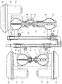
また、各バンク毎の1対のスロットル弁11の弁軸12は、図5に図示されるように、一直線状に配置され、この一直線状に配置された1対の弁軸12には、それぞれアーム21、22が半径方向へ一体に突設され、これら1対のアーム21、22の先端は連結部材23でもって相互に一体に連結され、前バンクの左側のアーム21と後バンクの左側のアーム21とは、リンク24でもって同時に同一角度回転できるように連結されている。
Further, as shown in FIG. 5, the
さらに、図6に図示されるように、前バンクの左側弁軸12の左端部には、スロットル弁駆動歯車26が一体に嵌着され、該スロットル弁駆動歯車26は、中間減速歯車27の小歯車28に噛み合わされ、中間減速歯車27の大歯車29は、スロットル駆動モータ31の出力歯車30に噛み合わされ、これら減速機構25、スロットル弁駆動歯車26および出力歯車30の各中心は、図2に図示されるように直線に沿って配列され、その配列直線とスロットル弁ボディ10および吸気管13の中心線とのなす角は約70°に設定されており、スロットル駆動モータ31が動作して、弁軸12がいずれかの方向へ旋回駆動されると、スロットル弁11が開閉されるようになっている。
Further, as shown in FIG. 6, a throttle
さらにまた、前記スロットル駆動モータ31は、前バンクの左側スロットル弁ボディ10と一体に形成されたスロットル弁駆動ユニットケース32の駆動モータ収納部33に収納され、中間減速歯車27を回転自在に軸支する歯車軸35は、スロットル弁駆動ユニットケース32の孔と該スロットル弁駆動ユニットケース32内空間を密閉するユニットケースカバー34の孔とに嵌着されている。
Furthermore, the
しかも、スロットル駆動モータ31は、図5に図示されるように、Vバンクの平面視で、全吸気ポート9にそれぞれ付設されたスロットル弁ボディ10で囲まれた2点鎖線で図示される領域Xの外側に配置されている。
In addition, as shown in FIG. 5, the
そして、自動二輪車の図示されないグリップには、スロットル開度操作検出センサ(図示されず)が設けられるとともに、前バンクの左側アーム21の弁軸12の左端部にスロットル開度検出センサ36が配置され、これらスロットル開度操作検出センサの出力と、スロットル開度検出センサ36の出力とを比較して、この両出力の差を零にするように、大歯車29を制御する、図示されないスロットル制御装置が設けられており、ライダーがグリップを加速方向または減速方向へ操作すると、スロットル開度操作検出センサで検出されたスロットル開度操作検出値に対応して大歯車29が駆動されて、スロットルグリップのスロットル開度操作量に対応した開度にスロットル弁11が制御されるようになっている。
In addition, a throttle opening operation detection sensor (not shown) is provided on a grip (not shown) of the motorcycle, and a throttle
また、図2に図示されるように、シリンダ4のシリンダ孔7に開口する吸気ポート9の下流端には、吸気弁37が開閉自在に設けられ、該吸気弁37の頂端に嵌着されたリテーナ38と、シリンダヘッド5のバネ受け部とにバルブスプリング39が介装され、シリンダヘッド5には吸気弁37の摺動方向に沿ってバルブリフタ40を摺動させるリフタガイド41が形成され、該バルブリフタ40は図示されないクランク軸からチェーン伝動系を介して連結されたカムシャフト42の吸気カム43によって、吸気弁37の頂端に押し付けられ、吸気弁37は、クランク角に対応して開閉されるようになっている。さらに、図示されない排気弁も同様に構成されている。
As shown in FIG. 2, an
さらに、図2および図5に図示されるように、燃料噴射弁20に燃料を供給するU字に形成された燃料供給管44が配置され、この燃料供給管44の一端44aは図示されない燃料供給ポンプの吐出口に接続されるとともに、燃料供給管44の他端44bは前記燃料供給ポンプの吸入口に接続され、該燃料供給管44はそれぞれ、燃料噴射弁20に接続されている。
Further, as shown in FIGS. 2 and 5, a
図1ないし図6に図示の実施形態は、前述したように構成されているので、V型内燃機関1が稼動状態となると、空気吸入ダクト19の前端開口から走行に伴なう空気が空気吸入ダクト19内を通過してクリーナケース15のダスト空間17内に吸入され、クリーナエレメント18で吸入空気が濾過されて、クリーン空間16に流入し、クリーン空間16に開口した吸気管13からスロットル弁ボディ10の弁通路に流入する。
Since the embodiment shown in FIGS. 1 to 6 is configured as described above, when the V-type
ライダーが図示されないスロットルグリップを所要の角度に捩ると、この捩り角度は図示されないスロットル開度操作検出センサによって検出され、このスロットル開度操作信号に対応した角度迄スロットル駆動モータ31が動作し、スロットル弁11はそのスロットルグリップの操作角度に対応したスロットル弁開度に制御される。
When the rider twists a throttle grip (not shown) to a required angle, the twist angle is detected by a throttle opening operation detection sensor (not shown), and the
V型内燃機関1では、Vバンクの内側に位置してシリンダヘッド5の吸気ポート9にスロットル弁ボディ10が接続されているため、スロットル弁ボディ10の上流端に接続されている吸気管13の上流端は、図2に図示されるように相互に接近し、その結果、クリーナケース15の大型化が回避される。
In the V-type
また、クリーン空間16より前方にダスト空間17が配置され、ダスト空間17に下流端が接続される空気吸入ダクト19はメインフレーム2を貫通して前方へ向いているので、走行に伴なう走行風が円滑にクリーナケース15内のクリーン空間16に導入されうる。
In addition, a
さらに、燃料噴射弁20は、Vバンクの内側に位置し、スロットル弁ボディ10の下流側に向って斜めに取り付けられ、スロットル弁ボディ10の吸気通路の弯曲外側壁面10aに向って燃料噴射弁20より燃料が噴射されるため、スロットル弁ボディ10の吸気通路を通過する吸気と充分に混合され、かつ吸気通路の弯曲外側壁面10aに付近した燃料は、該吸気通路内を通過する吸気に晒される結果、スロットル弁ボディ10の吸気通路壁の燃料付着量が削減され、V型内燃機関1の運転応答性が高い。
Further, the
さらにまた、スロットル駆動モータ31および減速機構25が、前バンクの左側スロットル弁ボディ10の左外側に配置されているため、スロットル弁11の駆動系(スロットル駆動モータ31および減速機構25)の保守、点検、整備作業を容易に行うことが可能となる。
Furthermore, since the
しかも、減速機構25の減速歯車軸列は、スロットル弁ボディ10および吸気管13の中心線に対して約70°の角度をなして設けられているため、スロットル弁駆動ユニットケース32に大きく邪魔されずにクリーナケース15はV型内燃機関1のヘッドカバー6に接近して配置されることが可能となり、V型内燃機関1全体の小型化が可能となる。
Moreover, since the reduction gear shaft train of the
また、1個のスロットル駆動モータ31で前後Vバンクの4個のスロットル弁11を同時に開閉動作させることができるので、構造を簡略化し、コストダウンを図ることができる。
Further, since the four
さらに、図7に図示するように、第二実施形態として、Vバンクの平面視で、全スロットル弁ボディ10で囲まれた2点鎖線で囲まれた領域Xの外側に位置して、2個のスロットル駆動モータを配置し、タ31前バンクのスロットル弁11と後バンクのスロットル弁11とをそれぞれ別個のスロットル駆動モータ31で開閉動作させるように構成すれば、必要に応じて前後バンクのいずれか一方のシリンダ4を休止させることができる。
Further, as shown in FIG. 7, as a second embodiment, in the plan view of the V bank, two pieces are located outside a region X surrounded by a two-dot chain line surrounded by all
さらにまた、図8に図示するように、第三実施形態として、Vバンクの平面視で、全スロットル弁ボディ10で囲まれた2点鎖線で囲まれた領域Xの外側に位置して、3個のスロットル駆動モータを配置し、前バンクの左右1対のスロットル弁11をアーム21、22および連結部材23で相互に連結して、1個のスロットル駆動モータ31で開閉駆動させ、後バンクの左右1対のスロットル弁11を相互に連結せず、その各スロットル弁11をスロットル駆動モータ31でそれぞれ開閉させるように構成してもよく、該第三実施形態では、運動状況に対応して、前バンクの2個のスロットル弁11と、後バンクの左スロットル弁11と、後バンクの右スロットル弁11とを個別に気筒休止させ、あるいはスロットル開度を個別に制御し、最適な状態でV型内燃機関を運転させることができる。
Furthermore, as shown in FIG. 8, as a third embodiment, in a plan view of the V bank, it is located outside a region X surrounded by a two-dot chain line surrounded by all
また、図8に図示された第三実施形態において、U字状の燃料供給管44の代りにI字状の燃料供給管45を設け、該燃料供給管45の左端を図示されない燃料ポンプに接続し、燃料供給管45の右端を閉塞した第四実施形態を構成してもよい。
Further, in the third embodiment shown in FIG. 8, an I-shaped
1…V型内燃機関、2…メインフレーム、3…クランクケース、4…シリンダ、5…シリンダヘッド、6…ヘッドカバー、7…シリンダ孔、8…ピストン、9…吸気ポート、10…スロットル弁ボディ、11…スロットル弁、12…弁軸、13…吸気管、14…エアクリーナ、15…クリーナケース、16…クリーン空間、17…ダスト空間、18…クリーナエレメント、19…空気吸入ダクト、20…燃料噴射弁、21…アーム、22…アーム、23…連結部材、24…リンク、25…減速機構、26…スロットル弁駆動歯車、27…中間減速歯車、28…小歯車、29…大歯車、30…出力歯車、31…スロットル駆動モータ、32…スロットル弁駆動ユニットケース、33…駆動モータ収納部、34…ユニットケースカバー、35…歯車軸、36…スロットル開度検出センサ、37…吸気弁、38…リテーナ、39…バルブスプリング、40…バルブリフタ、41…リフタガイド、42…カムシャフト、43…吸気カム、44、45…燃料供給管。
DESCRIPTION OF
Claims (1)
前記自動二輪車用V型内燃機関は前側バンク2気筒と後側バンク2気筒からなる4気筒内燃機関(1)であり、後側バンクの各スロットル弁ボディ(10)は対向する前側バンクの各スロットル弁ボディ(10)に対して内側に偏倚して配置され、後側バンクに設けたスロットル弁ボディ(10)の弁軸(12)を駆動する前記スロットル駆動モータ(31)を後側バンクのスロットル弁ボディ(10)より後方に配置すると共に、前記スロットル弁駆動ユニットケース(32)を前記後側バンクのスロットル弁ボディ(10)の側面に設けたことを特徴とする自動二輪車用V型内燃機関の電子スロットル制御装置。 A fuel injection valve (20) and a throttle valve (11) are provided in the intake passage, and the opening degree of the throttle valve (11) is controlled by a throttle drive motor (31) that operates based on a human operation amount. The throttle drive motor (31) is arranged outside the area surrounded by the throttle valve body (10) attached to each of the intake ports (9) in plan view, and is controlled by the throttle drive motor (31). ) Is provided in parallel with the valve shaft (12) of the throttle valve body (10) and connects the throttle drive motor (31) and the valve shaft (12) with a gear train (26, 27, 28, 29, 30). In the electronic throttle control device for a V-type internal combustion engine for a motorcycle, in which a throttle valve drive unit case (32) in which
The V-type internal combustion engine for a motorcycle is a four-cylinder internal combustion engine (1) composed of two cylinders in the front bank and two cylinders in the rear bank, and each throttle valve body (10) in the rear bank is in each throttle in the opposite front bank. The throttle drive motor (31), which is disposed inwardly with respect to the valve body (10) and drives the valve shaft (12) of the throttle valve body (10) provided in the rear bank, has the throttle in the rear bank. A V-type internal combustion engine for a motorcycle , disposed behind the valve body (10) and provided with the throttle valve drive unit case (32) on a side surface of the throttle valve body (10) of the rear bank. Electronic throttle control device.
Priority Applications (6)
| Application Number | Priority Date | Filing Date | Title |
|---|---|---|---|
| JP2006270000A JP4799352B2 (en) | 2006-09-29 | 2006-09-29 | Electronic throttle control device for V-type internal combustion engine for vehicle |
| DE602007001223T DE602007001223D1 (en) | 2006-09-29 | 2007-08-10 | Electronic throttle control device in a V engine for vehicle |
| EP07015831A EP1908944B1 (en) | 2006-09-29 | 2007-08-10 | Electronic throttle control device in V-type internal combustion engine for vehicle |
| TW096130727A TW200818688A (en) | 2006-09-29 | 2007-08-20 | Electronic throttle control device in V-type internal combustion engine for vehicle |
| CN2007101543880A CN101153562B (en) | 2006-09-29 | 2007-09-26 | Electronic throttle control device in V-type internal combustion engine for vehicle |
| US11/902,920 US8020531B2 (en) | 2006-09-29 | 2007-09-26 | Electronic throttle control device in V-type internal combustion engine for vehicle |
Applications Claiming Priority (1)
| Application Number | Priority Date | Filing Date | Title |
|---|---|---|---|
| JP2006270000A JP4799352B2 (en) | 2006-09-29 | 2006-09-29 | Electronic throttle control device for V-type internal combustion engine for vehicle |
Publications (2)
| Publication Number | Publication Date |
|---|---|
| JP2008088873A JP2008088873A (en) | 2008-04-17 |
| JP4799352B2 true JP4799352B2 (en) | 2011-10-26 |
Family
ID=38474441
Family Applications (1)
| Application Number | Title | Priority Date | Filing Date |
|---|---|---|---|
| JP2006270000A Active JP4799352B2 (en) | 2006-09-29 | 2006-09-29 | Electronic throttle control device for V-type internal combustion engine for vehicle |
Country Status (6)
| Country | Link |
|---|---|
| US (1) | US8020531B2 (en) |
| EP (1) | EP1908944B1 (en) |
| JP (1) | JP4799352B2 (en) |
| CN (1) | CN101153562B (en) |
| DE (1) | DE602007001223D1 (en) |
| TW (1) | TW200818688A (en) |
Families Citing this family (13)
| Publication number | Priority date | Publication date | Assignee | Title |
|---|---|---|---|---|
| JP2009085111A (en) * | 2007-09-29 | 2009-04-23 | Honda Motor Co Ltd | Fuel supplying structure in v-type multi-cylinder engine |
| US8191515B2 (en) * | 2008-06-24 | 2012-06-05 | Honda Motor Co., Ltd. | V-type internal combustion engine including throttle valve device, and vehicle incorporating same |
| JP5215092B2 (en) * | 2008-09-08 | 2013-06-19 | 川崎重工業株式会社 | Engine and vehicle equipped with this |
| JP5854639B2 (en) * | 2010-05-25 | 2016-02-09 | 株式会社ミクニ | Throttle control device |
| US9381810B2 (en) | 2010-06-03 | 2016-07-05 | Polaris Industries Inc. | Electronic throttle control |
| BR112017008825A2 (en) | 2014-10-31 | 2018-03-27 | Polaris Inc | method and power steering system for a vehicle, methods for controlling a power steering system of a vehicle and for controlling a vehicle, throttle replacement method for a recreational vehicle, and, vehicle. |
| JP6366141B2 (en) * | 2015-05-29 | 2018-08-01 | 本田技研工業株式会社 | Saddle riding |
| US11110913B2 (en) | 2016-11-18 | 2021-09-07 | Polaris Industries Inc. | Vehicle having adjustable suspension |
| US10406884B2 (en) | 2017-06-09 | 2019-09-10 | Polaris Industries Inc. | Adjustable vehicle suspension system |
| JP7306172B2 (en) * | 2019-09-05 | 2023-07-11 | スズキ株式会社 | Engine, vehicle and engine control method |
| US11725596B2 (en) * | 2019-10-18 | 2023-08-15 | Hitachi Astemo, Ltd. | Intake control device |
| US11143117B2 (en) * | 2019-12-04 | 2021-10-12 | Mikuni Corporation | Throttle device |
| CA3182725A1 (en) | 2020-07-17 | 2022-01-20 | Polaris Industries Inc. | Adjustable suspensions and vehicle operation for off-road recreational vehicles |
Family Cites Families (17)
| Publication number | Priority date | Publication date | Assignee | Title |
|---|---|---|---|---|
| EP0378154B1 (en) * | 1989-01-11 | 1995-11-08 | Toray Industries, Inc. | Biaxially oriented polyester film |
| JPH0436020A (en) * | 1990-05-09 | 1992-02-06 | Mazda Motor Corp | Intake air suction device for engine |
| JP3422373B2 (en) * | 1993-09-29 | 2003-06-30 | 日産自動車株式会社 | V-type internal combustion engine throttle valve device |
| JP3352919B2 (en) * | 1997-09-24 | 2002-12-03 | 本田技研工業株式会社 | Start control valve device for multiple throttles |
| JP4494660B2 (en) * | 2001-03-05 | 2010-06-30 | ヤマハ発動機株式会社 | V-type engine throttle control device for motorcycles |
| US7089910B2 (en) * | 2002-07-12 | 2006-08-15 | Yamaha Marine Kabushiki Kaisha | Watercraft propulsion system and control method of the system |
| US7066142B2 (en) * | 2002-09-11 | 2006-06-27 | Mikuni Corporation | Multiple throttle apparatus |
| JP2004132290A (en) * | 2002-10-11 | 2004-04-30 | Mikuni Corp | Multiple throttle device |
| JP2004132289A (en) * | 2002-10-11 | 2004-04-30 | Mikuni Corp | Multiple throttle device |
| EP1550802A4 (en) | 2002-10-11 | 2007-02-28 | Mikuni Kogyo Kk | Throttle device |
| JP2004169628A (en) * | 2002-11-20 | 2004-06-17 | Mikuni Corp | Throttle device |
| JP4341811B2 (en) * | 2003-04-04 | 2009-10-14 | 本田技研工業株式会社 | Throttle valve opening control device |
| US7237528B2 (en) * | 2004-03-26 | 2007-07-03 | Kawasaki Jukogyo Kabushiki Kaisha | Throttle valve control device for leisure vehicle |
| JP2006042446A (en) | 2004-07-23 | 2006-02-09 | Yamaha Motor Co Ltd | Abnormality-monitoring apparatus for motor control system |
| JP4167635B2 (en) * | 2004-08-26 | 2008-10-15 | 本田技研工業株式会社 | Fuel supply device for V-type engine for vehicle |
| JP2006250083A (en) * | 2005-03-11 | 2006-09-21 | Honda Motor Co Ltd | Intake device of v-type internal combustion engine |
| JP4476144B2 (en) * | 2005-03-22 | 2010-06-09 | 本田技研工業株式会社 | Arrangement structure of idle air control device for internal combustion engine |
-
2006
- 2006-09-29 JP JP2006270000A patent/JP4799352B2/en active Active
-
2007
- 2007-08-10 DE DE602007001223T patent/DE602007001223D1/en active Active
- 2007-08-10 EP EP07015831A patent/EP1908944B1/en not_active Expired - Fee Related
- 2007-08-20 TW TW096130727A patent/TW200818688A/en not_active IP Right Cessation
- 2007-09-26 CN CN2007101543880A patent/CN101153562B/en not_active Expired - Fee Related
- 2007-09-26 US US11/902,920 patent/US8020531B2/en active Active
Also Published As
| Publication number | Publication date |
|---|---|
| US20080078355A1 (en) | 2008-04-03 |
| CN101153562A (en) | 2008-04-02 |
| DE602007001223D1 (en) | 2009-07-16 |
| TWI360290B (en) | 2012-03-11 |
| EP1908944A1 (en) | 2008-04-09 |
| JP2008088873A (en) | 2008-04-17 |
| US8020531B2 (en) | 2011-09-20 |
| CN101153562B (en) | 2010-04-14 |
| EP1908944B1 (en) | 2009-06-03 |
| TW200818688A (en) | 2008-04-16 |
Similar Documents
| Publication | Publication Date | Title |
|---|---|---|
| JP4799352B2 (en) | Electronic throttle control device for V-type internal combustion engine for vehicle | |
| US10526982B2 (en) | Internal combustion engine with supercharger for saddle-ride type vehicle | |
| US7533653B2 (en) | Intake air control system for a V-type internal combustion engine and engine incorporating same | |
| JP4609911B2 (en) | Throttle control device for motorcycle engine | |
| US20200032691A1 (en) | Exhaust pipe device of saddle-riding vehicle | |
| EP2339149A1 (en) | Saddle-ride-type vehicle | |
| JP2008088877A (en) | Intake device for v-type internal combustion engine | |
| JP2002256896A (en) | Throttle control device for engine | |
| JP2009197816A (en) | Engine | |
| US8042521B2 (en) | Engine unit and vehicle provided with the same | |
| JP2013108457A (en) | Arrangement structure for fuel injection device of motorcycle | |
| JP4476421B2 (en) | Motorcycle | |
| US10364755B2 (en) | Exhaust control device for engine | |
| WO2018163909A1 (en) | Air intake device for internal combustion engine | |
| US7690356B2 (en) | Internal combustion engine | |
| JP2011025763A (en) | Motorcycle | |
| JP5355673B2 (en) | engine | |
| JP4673876B2 (en) | Intake air amount control device for V-type multi-cylinder engine | |
| JP4916529B2 (en) | engine | |
| JP5143275B2 (en) | engine | |
| JP5856215B2 (en) | Saddle riding vehicle | |
| JP4916563B2 (en) | Throttle control device for motorcycle engine | |
| TWI664349B (en) | Internal combustion engine and straddled vehicle | |
| JP5874244B2 (en) | Secondary air supply device for internal combustion engine | |
| JP2009197814A (en) | Engine |
Legal Events
| Date | Code | Title | Description |
|---|---|---|---|
| A621 | Written request for application examination |
Free format text: JAPANESE INTERMEDIATE CODE: A621 Effective date: 20081126 |
|
| RD04 | Notification of resignation of power of attorney |
Free format text: JAPANESE INTERMEDIATE CODE: A7424 Effective date: 20090501 |
|
| A977 | Report on retrieval |
Free format text: JAPANESE INTERMEDIATE CODE: A971007 Effective date: 20100224 |
|
| A131 | Notification of reasons for refusal |
Free format text: JAPANESE INTERMEDIATE CODE: A131 Effective date: 20100302 |
|
| A521 | Written amendment |
Free format text: JAPANESE INTERMEDIATE CODE: A523 Effective date: 20100422 |
|
| A131 | Notification of reasons for refusal |
Free format text: JAPANESE INTERMEDIATE CODE: A131 Effective date: 20100518 |
|
| A521 | Written amendment |
Free format text: JAPANESE INTERMEDIATE CODE: A523 Effective date: 20100715 |
|
| A131 | Notification of reasons for refusal |
Free format text: JAPANESE INTERMEDIATE CODE: A131 Effective date: 20110111 |
|
| A521 | Written amendment |
Free format text: JAPANESE INTERMEDIATE CODE: A523 Effective date: 20110310 |
|
| TRDD | Decision of grant or rejection written | ||
| A01 | Written decision to grant a patent or to grant a registration (utility model) |
Free format text: JAPANESE INTERMEDIATE CODE: A01 Effective date: 20110802 |
|
| A01 | Written decision to grant a patent or to grant a registration (utility model) |
Free format text: JAPANESE INTERMEDIATE CODE: A01 |
|
| A61 | First payment of annual fees (during grant procedure) |
Free format text: JAPANESE INTERMEDIATE CODE: A61 Effective date: 20110802 |
|
| FPAY | Renewal fee payment (event date is renewal date of database) |
Free format text: PAYMENT UNTIL: 20140812 Year of fee payment: 3 |
|
| R150 | Certificate of patent or registration of utility model |
Free format text: JAPANESE INTERMEDIATE CODE: R150 Ref document number: 4799352 Country of ref document: JP Free format text: JAPANESE INTERMEDIATE CODE: R150 |
|
| R250 | Receipt of annual fees |
Free format text: JAPANESE INTERMEDIATE CODE: R250 |