EP2390457A2 - Drive device for awnings - Google Patents
Drive device for awnings Download PDFInfo
- Publication number
- EP2390457A2 EP2390457A2 EP20110004335 EP11004335A EP2390457A2 EP 2390457 A2 EP2390457 A2 EP 2390457A2 EP 20110004335 EP20110004335 EP 20110004335 EP 11004335 A EP11004335 A EP 11004335A EP 2390457 A2 EP2390457 A2 EP 2390457A2
- Authority
- EP
- European Patent Office
- Prior art keywords
- sleeve
- drive device
- motor
- engine
- engine head
- Prior art date
- Legal status (The legal status is an assumption and is not a legal conclusion. Google has not performed a legal analysis and makes no representation as to the accuracy of the status listed.)
- Withdrawn
Links
Images


Classifications
-
- E—FIXED CONSTRUCTIONS
- E06—DOORS, WINDOWS, SHUTTERS, OR ROLLER BLINDS IN GENERAL; LADDERS
- E06B—FIXED OR MOVABLE CLOSURES FOR OPENINGS IN BUILDINGS, VEHICLES, FENCES OR LIKE ENCLOSURES IN GENERAL, e.g. DOORS, WINDOWS, BLINDS, GATES
- E06B9/00—Screening or protective devices for wall or similar openings, with or without operating or securing mechanisms; Closures of similar construction
- E06B9/56—Operating, guiding or securing devices or arrangements for roll-type closures; Spring drums; Tape drums; Counterweighting arrangements therefor
- E06B9/68—Operating devices or mechanisms, e.g. with electric drive
- E06B9/72—Operating devices or mechanisms, e.g. with electric drive comprising an electric motor positioned inside the roller
-
- E—FIXED CONSTRUCTIONS
- E06—DOORS, WINDOWS, SHUTTERS, OR ROLLER BLINDS IN GENERAL; LADDERS
- E06B—FIXED OR MOVABLE CLOSURES FOR OPENINGS IN BUILDINGS, VEHICLES, FENCES OR LIKE ENCLOSURES IN GENERAL, e.g. DOORS, WINDOWS, BLINDS, GATES
- E06B9/00—Screening or protective devices for wall or similar openings, with or without operating or securing mechanisms; Closures of similar construction
- E06B9/02—Shutters, movable grilles, or other safety closing devices, e.g. against burglary
- E06B9/08—Roll-type closures
- E06B9/11—Roller shutters
- E06B9/17—Parts or details of roller shutters, e.g. suspension devices, shutter boxes, wicket doors, ventilation openings
- E06B9/174—Bearings specially adapted therefor
Definitions
- the invention relates to a drive device for shutters, awnings and the like according to the preamble of claim 1.
- Modular designed structures are already eg by the DE10258061 known, but always allow only one form of engine head, since in this the limit switch is integrated.
- the object of the invention is therefore to provide a drive device referred to in the preamble of claim 1, which allows a smaller storage volume for any conceivable geometric shape of the engine head and allows flexible action of the technician on site, which then corresponds to any installation situation the geometry and the installation length can react.
- the invention is in any case realized if it is a drive device for shutters, awnings and the like with a arranged in the winding tube, this driving, electric tubular motor, consisting of a body engine and serving as a fastening device for the engine hull in the winding tube engine head consists.
- the engine head is modular pluggable mounted on the fuselage engine.
- the drive device By the engine head, which can be coupled to the fuselage engine, the drive device is designed to be more complex.
- tubular motors with different powers which preferably differ in different lengths, can be combined with different motor heads (different geometric shapes). Therefore, a length compensation can take place without having to replace the entire engine.
- the engine heads can be adapted to different fastening systems. This separation of engine head and body engine also provides a manufacturer, assembly and storage advantage.
- Fig. 1 a perspective complete view of a tubular motor of the engine and engine head
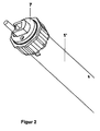
- Fig. 2 a perspective complete view of a tube engine from the engine trunk and an alternative engine head
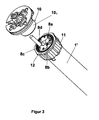
- Fig. 3 an exploded perspective view of the fuselage engine and engine head of Fig. 1 from the beginning
- Fig. 4 an exploded perspective view of the fuselage engine and engine head of Fig. 1 from behind
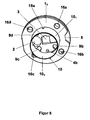
- Fig. 5 a perspective view of the engine head of Fig. 1 from behind
- Fig. 6 a perspective view of the engine head of Fig. 1 from the beginning
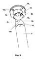
- Fig. 7 a perspective view of the alternative engine head of Fig. 2 from behind
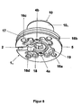
- Fig. 8 a perspective view of the alternative engine head of Fig. 2 from the front and
- Fig. 9 a perspective view of the fuselage engine of Fig. 1 or 2.
- Fig. 1 is a complete tubular motor of a fuselage engine 1 'and a modular engine head 1 shown.
- the engine head 1 has the shape of a sleeve 10 (FIG. Fig. 3 ) with a sleeve bottom 1 1 , which is provided with a cable passage 2 for carrying a supply line 6 and with a polygonal passage 3.
- the passage 3 serves to receive a complementary bolt (not shown) which is fastened, for example, to a roller shutter box side part (not shown).
- the passage 3 and the complementary bolt serve for the axial and radial mounting of the tube motor.
- 1 1 breakthroughs 4 a, 4 b are arranged in the sleeve bottom, which serve to receive fastening means, not shown.
- a groove 5 at the edge of the sleeve bottom 1 1 is present, which serves to receive a fastening spring, not shown.
- a connection of the hull motor 1 'with a winding shaft of the shutter and thus the drive of this winding shaft is located on the motor head 1 opposite end of the tube motor (not shown).
- Fig. 2 For example, the same body engine 1 'is provided with an exemplary alternative engine head 7.
- This alternative engine head 7 is used because of its very small design when a very cramped installation situation exists. He will be described in more detail.
- FIG. 3 and 4 is the complete tubular motor of Fig. 1 to see with raptured engine head 1 once from the front and once from behind.
- At the end of the hull motor 1 'four applications 8a-8d are arranged, which are evenly distributed on the circumference of the hull motor 1' and serve for accommodation in four complementary recesses 9a-9d, which after Fig. 4 are arranged in the sleeve bottom 1 1 and can have any conceivable geometric shape.
- a first surface 10 1 of the sleeve 1 1 is designed such that it is suitable for receiving a tubular Rohrmit counselings 11, the Rohrmit counseling 11 a first surface 12, namely the inner surface, which is complementary to the first surface 10th 1 is formed and allows a rotational movement of the pivot bearing formed with the first surfaces.
- the driver 11 is thus part of a pivot bearing. The toothing on the driver 11 is used to count the revolutions.
- a second surface 10 2 of the sleeve 1 1 is complementary to a second surface 14 of the hull motor 1 ', namely its outer end surface formed.
- An opening 15a in the sleeve 1 1 and a congruent arranged breakthrough 15b in the surface 14 serve for the axial unlocking of the connection between said, not shown bolt and the fuselage engine 1 'by means of a pin, said connection, for example by latching means of a sprung pressure piece can be formed.
- FIG. 5 and 6 are perspective views of the engine head of Fig. 1 once shown from the back and once from the front.
- Out Fig. 5 shows that the sleeve bottom 1 1 with an edge 1 2 well above the circumference of the sleeve 10 extends. In this edge 1 2 evenly four mounting holes 16a-16d are provided by the fastening means for fastening the tubular motor to eg a roller shutter side part are feasible.
- Out Fig. 6 are further breakthroughs 17-19 in the sleeve bottom 1 1 can be seen , which serve to save material.
- FIGS. 7 and 8th FIG. 15 are perspective views of the alternative engine head of FIG Fig. 2 once shown from the back and once from the front.
- Out Fig. 7 shows that the sleeve bottom 1 1 extends with only a narrow stop edge 1 2 'over the circumference of the sleeve 10.
- Out Fig. 8 can also be seen that a central attachment 20 is arranged on the casing base 1. 1 By this essay 20 of the polygenic passage 3 is continued.
- the two mounting holes 4a, 4b can be seen, which serve to attach the tubular motor to eg the roller shutter side part.
- the Fig. 9 shows the formation of the end of the hull engine 1 'without engine head. It can be seen the four applications 8a-8d and mounting holes 4a 'and 4b'. Through the hole 15b of the pin for triggering the sprung pressure piece in the bolt can be guided.
- engine heads shown in the figures are given by way of example only and are not intended to limit the scope of the invention in any way; Rather, the outer shape of the engine heads can be adapted to the conditions at the place of use (eg shutter box).
Abstract
Description
Die Erfindung betrifft eine Antriebsvorrichtung für Rollläden, Markisen und dergleichen gemäß dem Oberbegriff des Anspruchs 1.The invention relates to a drive device for shutters, awnings and the like according to the preamble of
Bei Antriebsvorrichtungen auf dem Gebiet der Rollladen-Markisenantrieb und dergleichen ist ein als Befestigungsvorrichtung dienender Motorkopf mit der Antriebseinheit fest verankert. Dadurch wird die Lagerhaltung der Antriebseinheiten erschwert, da jede Antriebseinheit komplett auf Lager gehalten werden muss. Dadurch entstehen hohe Lagerkosten und ein hoher Lagerplatzbedarf. Ferner lässt diese Bauform eine Entscheidung, welcher Motortyp auf der Baustelle verbaut werden soll, nur vorab im Lager zu, da der komplette Motor mit Befestigungsvorrichtung mitgenommen werden muss.In drive devices in the field of roller shutter awning drive and the like serving as a fastening device engine head with the drive unit is firmly anchored. As a result, the storage of drive units is difficult because each drive unit must be kept completely in stock. This results in high storage costs and a high storage space requirement. Furthermore, this design allows a decision as to which type of engine is to be installed on the construction site, only in advance in the warehouse, since the entire engine has to be taken with a fastening device.
Modular gestaltete Aufbauten sind schon z.B. durch die
Ein weiterer Nachteil ist, dass die Einbausituation, d.h. welche Form der Motorkopf haben muss, nicht vorn Monteur vor Ort flexibel getroffen werden kann, sondern aufwändig im Vorfeld geklärt werden muss, da der Monteur unmöglich jede Antriebsvorrichtungsvariante als komplettes Bauteil in seinem Fahrzeug mitführen kann.Another disadvantage is that the installation situation, i. which form the engine head must have, can not be flexibly taken by the field mechanic on site, but must be clarified in advance in advance, since the fitter can not carry any drive device variant as a complete component in his vehicle.
Die Aufgabe der Erfindung besteht daher darin, eine Antriebsvorrichtung der im Oberbegriff des Anspruchs 1 genannten Art zu schaffen, die ein kleineres Lagervolumen für jede denkbare, geometrische Form des Motorkopfs zulässt und ein flexibles Handeln des Monteurs vor Ort erlaubt, der dann auf jede Einbausituation entsprechend der Geometrie und der Einbaulänge reagieren kann.The object of the invention is therefore to provide a drive device referred to in the preamble of
Diese Aufgabe wird mit den Merkmalen des Anspruchs 1 gelöst. Man erkennt dass die Erfindung jedenfalls dann verwirklicht ist, wenn es sich um eine Antriebsvorrichtung für Rollläden, Markisen und dergleichen mit einem im Wickelrohr angeordneten, dieses antreibenden, elektrischen Rohrmotor handelt, der aus einem Rumpfmotor und einem als Befestigungsvorrichtung für den Rumpfmotor im Wickelrohr dienenden Motorkopf besteht. Der Motorkopf ist modular steckbar am Rumpfmotor angebracht.This object is achieved with the features of
Durch den an den Rumpfmotor ankoppelbaren Motorkopf ist die Antriebsvorrichtung kombinationsreicher ausgestaltet. So können Rohrmotoren mit unterschiedlichen Leistungen, die sich vorzugsweise durch verschiedene Längen unterscheiden, mit unterschiedlichen Motorköpfen (unterschiedliche, geometrische Formen) kombiniert werden. Daher kann ein Längenausgleich stattfinden, ohne den kompletten Motor austauschen zu müssen.By the engine head, which can be coupled to the fuselage engine, the drive device is designed to be more complex. Thus tubular motors with different powers, which preferably differ in different lengths, can be combined with different motor heads (different geometric shapes). Therefore, a length compensation can take place without having to replace the entire engine.
Die Motorköpfe können an verschiedene Befestigungssysteme angepasst werden. Durch diese Trennung von Motorkopf und Rumpfmotor wird ebenso ein Hersteller-, Montage- und Lagervorteil erreicht.The engine heads can be adapted to different fastening systems. This separation of engine head and body engine also provides a manufacturer, assembly and storage advantage.
Einfache, weitere Ausbildungen der Erfindung sind in den Unteransprüchen niedergelegt.Simple, further embodiments of the invention are set forth in the dependent claims.
Die Erfindung wird nun anhand von Ausführungsbeispielen näher erläutert. Es zeigen:The invention will now be explained in more detail with reference to exemplary embodiments. Show it:
In
Weiterhin ist eine Nut 5 am Rand des Hülsenbodens 11 vorhanden, die zur Aufnahme einer nicht dargestellten Befestigungsfeder dient. Eine Verbindung des Rumpfmotors 1' mit einer Wickelwelle des Rollladens und damit der Antrieb dieser Wickelwelle liegt auf der dem Motorkopf 1 gegenüberliegenden Ende des Rohrmotors (nicht gezeigt).In
Furthermore, a
In
In den
Eine erste Fläche 101 der Hülse 11, nämlich deren Außenfläche, ist derart ausgebildet, dass sie zur Aufnahme eines hülsenförmigen Rohrmitnehmers 11 geeignet ist, wobei der Rohrmitnehmer 11 eine erste Fläche 12, nämlich dessen Innenfläche, aufweist, die komplementär zur ersten Fläche 101 ausgebildet ist und eine Drehbewegung des mit den ersten Flächen gebildeten Drehlagers zulässt. Beim Mitnehmer 11 handelt es sich damit um ein Teil eines Drehlagers. Die Verzahnung am Mitnehmer 11 dient zum Zählen der Umdrehungen.A
Eine zweite Fläche 102 der Hülse 11, nämlich deren Innenfläche, ist komplementär zu einer zweiten Fläche 14 des Rumpfmotors 1', nämlich dessen Außenendfläche, ausgebildet. Ein Durchbruch 15a in der Hülse 11 und ein deckungsgleich angeordneter Durchbruch 15b in der Fläche 14 dienen zur axialen Entriegelung der Verbindung zwischen dem erwähnten, nicht dargestellten Bolzen und dem Rumpfmotor 1' mittels eines Stifts, wobei diese Verbindung beispielsweise durch Verrastung mittels eines gefederten Druckstücks gebildet sein kann.A
In den
In den
In den
Die
Die in den Figuren dargestellten Motorköpfe sind nur beispielhaft angegeben und sollen den Schutzumfang der Erfindung keinesfalls beschränken; vielmehr kann die äußere Form der Motorköpfe jeweils den Bedingungen am Einsatzort (z.B. Rollladenkasten) angepasst werden.The engine heads shown in the figures are given by way of example only and are not intended to limit the scope of the invention in any way; Rather, the outer shape of the engine heads can be adapted to the conditions at the place of use (eg shutter box).
- 11
- Motorkopfmotor head
- 1'1'
- Rumpfmotorshort block
- 11 1 1
- Hülsenbodensleeve base
- 12 1 2
-
Rand des Hülsenbodens 11 Edge of the
case bottom 1 1 - 12' 1 2 '
-
Anschlagrand des Hülsenbodens des Motorkopfs 7Stop edge of the sleeve bottom of the
engine head 7 - 22
- KabeldurchlassCable outlet
- 33
-
Polygoner Durchlass des Hülsenbodens 11 Polygoner passage of the
case bottom 1 1 - 3'3 '
- Polygoner Durchlass des Rumpfmotors 1'Polygon passage of the hull motor 1 '
- 4a, 4b4a, 4b
- Durchbruchbreakthrough
- 55
- Nutgroove
- 66
- Versorgungsleitungsupply line
- 77
- Alternativer MotorkopfAlternative engine head
- 8a-8d8a-8d
- Aufbringungenboardings
- 9a-9d9a-9d
- EinnehmungenEinnehmungen
- 1010
- Hülseshell
- 101 10 1
- Erste Fläche der Hülse 10First surface of the sleeve 10th
- 102 10 2
- Zweite Fläche der Hülse 10Second surface of the sleeve 10th
- 1111
- Rohrmitnehmertubular carrier
- 1212
-
Erste Fläche des Rohrmitnehmers 11First surface of the
pipe driver 11 - 1414
- Zweite Fläche des Rumpfmotors 1'Second surface of the fuselage engine 1 '
- 15a, 15b15a, 15b
- Durchbruchbreakthrough
- 16a-16d16a-16d
- Befestigungsbohrungmounting hole
- 17-1917-19
- Durchbruchbreakthrough
- 2020
- Aufsatzessay
Claims (10)
dadurch gekennzeichnet,
dass der Motorkopf (1, 7) modular steckbar am Rumpfmotor (1') angebracht ist.Drive device for shutters, awnings and the like with an arranged in the winding tube, this driving, tubular electric motor consisting of a hull motor (1 ') and serving as a fastening device for the fuselage engine (1') in the winding tube engine head,
characterized,
that the engine head is mounted (1, 7) pluggable modular motor to the hull (1 ').
dadurch gekennzeichnet,
dass der Motorkopf (1) aus einer Hülse (10) und einem Hülsenboden (11) besteht.Drive device according to claim 1,
characterized,
that the engine head (1) consists of a sleeve (10) and a sleeve base (1 1).
dadurch gekennzeichnet,
dass der Hülsenboden (11) einen deutlich über den Umfang der Hülse (10) überstehenden Rand (12) aufweist, der mit verteilten Befestigungsbohrungen (16a-16d) versehen ist.Drive device according to claim 2,
characterized,
that the sleeve base (1 1) has a considerably over the circumference of the sleeve (10) protruding edge (2: 1) provided with distributed fastening holes (16a-16d) is provided.
dadurch gekennzeichnet,
dass der Hülsenboden (11) einen nur wenig über den Umfang der Hülse (10) überstehenden Anschlagrand (12') aufweist und dass im Hülsenboden (11) zwei Befestigungsbohrungen (4a, 4b) vorgesehen sind.Drive device according to claim 2,
characterized,
that the sleeve base (1 1) has a little over the circumference of the sleeve (10) projecting stop face (1 2 ') and that in the case bottom (1 1) has two mounting holes (4a, 4b) are provided.
dadurch gekennzeichnet,
dass der Hülsenboden (11) und das Ende des Rumpfmotors (1') mit einem zentralen, polygonen Durchlass (3, 3') zur Aufnahme eines feststehenden Bolzens versehen ist.Drive device according to one of claims 2 to 4,
characterized,
that the sleeve base (1 1) and the end of the short motor (1 ') with a central polygonal passage (3, 3') is provided for receiving a fixed bolt.
dadurch gekennzeichnet,
dass auf dem Hülsenboden außen ein zentraler Aufsatz (20) vorgesehen ist, durch den der zentrale, polygone Durchlass (3) weitergeführt ist.Drive device according to claims 4 and 5,
characterized,
that on the sleeve bottom outside a central attachment (20) is provided through which the central, polygonal passage (3) is continued.
dadurch gekennzeichnet,
dass der Bolzen ein gefedertes Druckstück aufweist, das in den Durchlass (3, 3') einrastbar ist.Drive device according to claim 5,
characterized,
that the bolt has a spring-loaded pressure piece which can be engaged in the passage (3, 3 ').
dadurch gekennzeichnet,
dass ein Durchbruch (15a) in der Hülse (11) und ein deckungsgleich angeordneter Durchbruch (15b) im Rumpfmotor (1', Fläche 14) vorgesehen sind, die zur axialen Entriegelung der Verbindung zwischen dem Bolzen und dem Rumpfmotor (1') mittels eines Stifts dienen.Drive device according to claim 7,
characterized,
that an opening (15a) in the sleeve (1 1) and a congruently arranged opening (15b) in the short block (1 ', surface 14) are provided for the axial unlocking of the connection between the bolt and the short motor (1') by means of serve a pin.
dadurch gekennzeichnet,
dass im Hülsenboden (11) Einnehmungen (9a-9d) und am Rumpfmotor (1') komplementäre Aufbringungen (8a-8d) vorgesehen sind, die in die Einnehmungen einbringbar sind.Drive device according to one of claims 2 to 8,
characterized,
that in the case bottom (1 1) Einnehmungen (9a-9d) and the fuselage motor (1 ') complementary depositions (8a-8d) are provided which are introduced into the Einnehmungen.
dadurch gekennzeichnet,
dass eine erste Fläche (101) der Hülse (11), nämlich deren Außenfläche, derart ausgebildet ist, dass sie zur Aufnahme eines hülsenförmigen Rohrmitnehmers (11) geeignet ist, wobei der Rohrmitnehmer (11) eine erste Fläche (12), nämlich dessen Innenfläche, aufweist, die komplementär zur ersten Fläche (101) der Hülse (11) ausgebildet ist und eine Drehbewegung des mit den ersten Flächen (101, 12) gebildeten Drehlagers zulässt.Drive device according to one of claims 2 to 9,
characterized,
that a first surface (10 1) of the sleeve (1 1), namely the outer surface thereof is formed such that it is adapted to receive a sleeve-shaped Rohrmitnehmers (11), wherein said tubular carrier (11) has a first surface (12), namely the inner surface, which is complementary to the first surface (10 1 ) of the sleeve (1 1 ) is formed and a rotational movement of the first surfaces (10 1 , 12) formed pivot bearing permits.
Applications Claiming Priority (1)
| Application Number | Priority Date | Filing Date | Title |
|---|---|---|---|
| DE102010021517 | 2010-05-26 |
Publications (1)
| Publication Number | Publication Date |
|---|---|
| EP2390457A2 true EP2390457A2 (en) | 2011-11-30 |
Family
ID=44117173
Family Applications (1)
| Application Number | Title | Priority Date | Filing Date |
|---|---|---|---|
| EP20110004335 Withdrawn EP2390457A2 (en) | 2010-05-26 | 2011-05-26 | Drive device for awnings |
Country Status (1)
| Country | Link |
|---|---|
| EP (1) | EP2390457A2 (en) |
Cited By (2)
| Publication number | Priority date | Publication date | Assignee | Title |
|---|---|---|---|---|
| ITCO20120051A1 (en) * | 2012-10-03 | 2014-04-04 | Cherubini Spa | TUBULAR MOTOR WITH SUPPORT FOR A FIXING ELEMENT |
| EP3514317A1 (en) * | 2018-01-17 | 2019-07-24 | Breemersch NV | Roller blind assembly and mounting element |
Citations (1)
| Publication number | Priority date | Publication date | Assignee | Title |
|---|---|---|---|---|
| DE10258061A1 (en) | 2002-12-11 | 2004-06-24 | Gerhard Geiger Gmbh & Co | Drive device for a roller shutter or canvas awning has an electrical pipe motor housed within the shutter tube with a coupling that links the motor to a shut-off unit |
-
2011
- 2011-05-26 EP EP20110004335 patent/EP2390457A2/en not_active Withdrawn
Patent Citations (1)
| Publication number | Priority date | Publication date | Assignee | Title |
|---|---|---|---|---|
| DE10258061A1 (en) | 2002-12-11 | 2004-06-24 | Gerhard Geiger Gmbh & Co | Drive device for a roller shutter or canvas awning has an electrical pipe motor housed within the shutter tube with a coupling that links the motor to a shut-off unit |
Cited By (5)
| Publication number | Priority date | Publication date | Assignee | Title |
|---|---|---|---|---|
| ITCO20120051A1 (en) * | 2012-10-03 | 2014-04-04 | Cherubini Spa | TUBULAR MOTOR WITH SUPPORT FOR A FIXING ELEMENT |
| CN103711420A (en) * | 2012-10-03 | 2014-04-09 | 凯鲁比尼股份公司 | Tubular motor with support for fixing element |
| EP2716859A1 (en) * | 2012-10-03 | 2014-04-09 | Cherubini S.p.A. | Tubular motor with support for a fixing element |
| EP3514317A1 (en) * | 2018-01-17 | 2019-07-24 | Breemersch NV | Roller blind assembly and mounting element |
| BE1025940B1 (en) * | 2018-01-17 | 2019-08-21 | Breemersch Nv | Roller blind assembly and mounting element |
Similar Documents
| Publication | Publication Date | Title |
|---|---|---|
| EP3304655B1 (en) | Locking system for a charging plug | |
| EP3122520A1 (en) | Robot arm and assembly set | |
| DE102005059383B4 (en) | System for compensating for differences in length between a cylinder lock to be inserted into an opening of a door leaf and the door leaf | |
| DE102014225978A1 (en) | Temperature sensor unit for an electric motor, in particular for the electric motor of a motor vehicle | |
| WO2001036903A1 (en) | Measuring rope-path sensor | |
| DE102017004153A1 (en) | drive fixation | |
| EP3205794B1 (en) | Handle system and method of assembly | |
| EP2390457A2 (en) | Drive device for awnings | |
| DE102006019576B4 (en) | Steering device for vehicles and method for mounting a bearing assembly | |
| DE10219245B4 (en) | Method for separating a encoder shaft of a rotary encoder from a drive shaft | |
| DE102007058331A1 (en) | Motor vehicle seat, has bearing/connecting element formed as U-shaped molding part with U-brackets and U-bar, which form retaining chamber for retaining cross tube, and spring element loading cross tube, if element is attached on tube | |
| EP3482480B1 (en) | Fastening arrangement of an electric motor and seat | |
| DE102006028073B4 (en) | Detent joint and exterior mirrors for motor vehicles with such a locking joint | |
| DE202006006083U1 (en) | Window lifter e.g. single- or double-stranded rope or Bowden cable window lifter, for motor vehicle, has upper and lower housings directly pivoted in guide rail, where housings are pivoted between clamping part and housings by clamping rail | |
| DE3325837C2 (en) | Device for adjusting and locking a window pane, in particular in a motor vehicle | |
| DE102016226144B4 (en) | Drive arrangement and method for their production as well as vehicle seat | |
| WO1995034764A1 (en) | Coupling device | |
| DE102006005675A1 (en) | Fitting for window, door or gate has two base plates sandwiching the frame and connected reversibly by two-part bolt | |
| EP3765244A1 (en) | Manipulator having joints and multi-functional profile for same | |
| DE102010050290A1 (en) | jig | |
| DE102016124543A1 (en) | Arrangement of a closing aid on a door lock of a motor vehicle door | |
| DE20318344U1 (en) | Electric motor housing has housing and flange elements that can be arranged in series in any numbers with adjacent housing elements rotated by 90 degrees relative to each other | |
| DE102007047126B4 (en) | Wiper system, method for mounting a wiper system and motor vehicle | |
| DE202020101872U1 (en) | Marking device for marking circuit cards tested with a test device | |
| DE102007018998A1 (en) | Shutter box |
Legal Events
| Date | Code | Title | Description |
|---|---|---|---|
| AK | Designated contracting states |
Kind code of ref document: A2 Designated state(s): AL AT BE BG CH CY CZ DE DK EE ES FI FR GB GR HR HU IE IS IT LI LT LU LV MC MK MT NL NO PL PT RO RS SE SI SK SM TR |
|
| AX | Request for extension of the european patent |
Extension state: BA ME |
|
| PUAI | Public reference made under article 153(3) epc to a published international application that has entered the european phase |
Free format text: ORIGINAL CODE: 0009012 |
|
| STAA | Information on the status of an ep patent application or granted ep patent |
Free format text: STATUS: THE APPLICATION IS DEEMED TO BE WITHDRAWN |
|
| 18D | Application deemed to be withdrawn |
Effective date: 20151201 |