EP2390210A2 - Dispositif et procédé d'ouverture de produits d'imprimerie - Google Patents
Dispositif et procédé d'ouverture de produits d'imprimerie Download PDFInfo
- Publication number
- EP2390210A2 EP2390210A2 EP11405259A EP11405259A EP2390210A2 EP 2390210 A2 EP2390210 A2 EP 2390210A2 EP 11405259 A EP11405259 A EP 11405259A EP 11405259 A EP11405259 A EP 11405259A EP 2390210 A2 EP2390210 A2 EP 2390210A2
- Authority
- EP
- European Patent Office
- Prior art keywords
- opening
- channel
- printed product
- edge region
- free edge
- Prior art date
- Legal status (The legal status is an assumption and is not a legal conclusion. Google has not performed a legal analysis and makes no representation as to the accuracy of the status listed.)
- Granted
Links
- 238000000034 method Methods 0.000 title claims abstract description 25
- 238000012546 transfer Methods 0.000 claims description 4
- 230000000149 penetrating effect Effects 0.000 claims 1
- 125000006850 spacer group Chemical group 0.000 description 8
- 238000012545 processing Methods 0.000 description 7
- 230000015572 biosynthetic process Effects 0.000 description 3
- 230000001360 synchronised effect Effects 0.000 description 3
- 241000270295 Serpentes Species 0.000 description 2
- 238000007664 blowing Methods 0.000 description 2
- 238000010924 continuous production Methods 0.000 description 2
- 230000001419 dependent effect Effects 0.000 description 2
- WYWHKKSPHMUBEB-UHFFFAOYSA-N 6-Mercaptoguanine Natural products N1C(N)=NC(=S)C2=C1N=CN2 WYWHKKSPHMUBEB-UHFFFAOYSA-N 0.000 description 1
- 239000000853 adhesive Substances 0.000 description 1
- 230000001070 adhesive effect Effects 0.000 description 1
- 238000005452 bending Methods 0.000 description 1
- 210000000078 claw Anatomy 0.000 description 1
- 230000001627 detrimental effect Effects 0.000 description 1
- 238000011161 development Methods 0.000 description 1
- 230000004941 influx Effects 0.000 description 1
- 238000003780 insertion Methods 0.000 description 1
- 230000037431 insertion Effects 0.000 description 1
- 230000002093 peripheral effect Effects 0.000 description 1
- 230000001007 puffing effect Effects 0.000 description 1
- 229940095374 tabloid Drugs 0.000 description 1
- 230000008719 thickening Effects 0.000 description 1
Images


Classifications
-
- B—PERFORMING OPERATIONS; TRANSPORTING
- B65—CONVEYING; PACKING; STORING; HANDLING THIN OR FILAMENTARY MATERIAL
- B65H—HANDLING THIN OR FILAMENTARY MATERIAL, e.g. SHEETS, WEBS, CABLES
- B65H5/00—Feeding articles separated from piles; Feeding articles to machines
- B65H5/30—Opening devices for folded sheets or signatures
- B65H5/308—Opening devices for folded sheets or signatures the folded sheets or signatures travelling in hanging position
-
- B—PERFORMING OPERATIONS; TRANSPORTING
- B65—CONVEYING; PACKING; STORING; HANDLING THIN OR FILAMENTARY MATERIAL
- B65H—HANDLING THIN OR FILAMENTARY MATERIAL, e.g. SHEETS, WEBS, CABLES
- B65H29/00—Delivering or advancing articles from machines; Advancing articles to or into piles
- B65H29/003—Delivering or advancing articles from machines; Advancing articles to or into piles by grippers
-
- B—PERFORMING OPERATIONS; TRANSPORTING
- B65—CONVEYING; PACKING; STORING; HANDLING THIN OR FILAMENTARY MATERIAL
- B65H—HANDLING THIN OR FILAMENTARY MATERIAL, e.g. SHEETS, WEBS, CABLES
- B65H2301/00—Handling processes for sheets or webs
- B65H2301/30—Orientation, displacement, position of the handled material
- B65H2301/32—Orientation of handled material
- B65H2301/323—Hanging
-
- B—PERFORMING OPERATIONS; TRANSPORTING
- B65—CONVEYING; PACKING; STORING; HANDLING THIN OR FILAMENTARY MATERIAL
- B65H—HANDLING THIN OR FILAMENTARY MATERIAL, e.g. SHEETS, WEBS, CABLES
- B65H2301/00—Handling processes for sheets or webs
- B65H2301/40—Type of handling process
- B65H2301/44—Moving, forwarding, guiding material
- B65H2301/447—Moving, forwarding, guiding material transferring material between transport devices
- B65H2301/4471—Grippers, e.g. moved in paths enclosing an area
- B65H2301/44712—Grippers, e.g. moved in paths enclosing an area carried by chains or bands
-
- B—PERFORMING OPERATIONS; TRANSPORTING
- B65—CONVEYING; PACKING; STORING; HANDLING THIN OR FILAMENTARY MATERIAL
- B65H—HANDLING THIN OR FILAMENTARY MATERIAL, e.g. SHEETS, WEBS, CABLES
- B65H2406/00—Means using fluid
- B65H2406/10—Means using fluid made only for exhausting gaseous medium
- B65H2406/12—Means using fluid made only for exhausting gaseous medium producing gas blast
-
- B—PERFORMING OPERATIONS; TRANSPORTING
- B65—CONVEYING; PACKING; STORING; HANDLING THIN OR FILAMENTARY MATERIAL
- B65H—HANDLING THIN OR FILAMENTARY MATERIAL, e.g. SHEETS, WEBS, CABLES
- B65H2701/00—Handled material; Storage means
- B65H2701/10—Handled articles or webs
- B65H2701/19—Specific article or web
- B65H2701/1932—Signatures, folded printed matter, newspapers or parts thereof and books
Definitions
- the invention relates to a method and a device for opening and further transporting printed products, each having at least two sheets held together by a fixed edge, comprising a conveying device with transport grippers driven in a conveying direction (F) and arranged at a distance one behind the other Printing products to be suspended from their fixed edge, and containing an opening unit arranged below the conveyor, which is intended to open the printed products, the opening unit gas supply means for generating a gas flow, by means of which the sheets of the printed product can be fluffed in a free edge area, and contains an opening element which can be inserted in the fluffed, free edge region of the printed product,
- the EP 1 908 714 B1 In contrast, describes an opening device with a wedge element, by means of which the opening of a file folder is possible during the promotion.
- the EP 1 090 867 B1 describes a device for opening folded printed products with Vorfalz, the printed matter for this purpose are introduced into pockets and opened by mechanical means such as clamp stop, hook element and pressure rail with gripping hooks.
- this device only works for two-sided printed products with a prefold.
- the EP-B-0 577 964 again, describes an apparatus and method for opening multi-sheet printed products.
- the printed products are exposed to a gas stream at a free edge, resulting in a fanning of the leaves in this edge region.
- An opening element is then retracted into the fanned-out edge area, which opens the product for further processing.
- the printed product is introduced according to a specific embodiment in a receiving cell with side walls. The side walls serve to limit the fanning, which is thus uniform.
- the device should thus be applicable in particular to a greater variety of printed products, in particular also to multi-leaf, cut printed products.
- the device and the method for Be designed printing products whose conveying direction is not parallel to the main plane of the leaves, and in particular substantially orthogonal to the main plane of the leaves.
- the device and the method should be applicable independently of the further processing steps.
- the printed products to be opened are multi-leaved, the individual sheets being held together by a fixed edge of the printed product.
- the nature of the connection of the sheets to the fixed edge of the printed product may be temporary or permanent.
- the sheets at the fixed edge of the printed product may become loose, i. separated from each other, for. B as a stack, be arranged side by side and are held together only by a temporary holding means.
- the sheets can also be held together at the fixed edge by a fold, a binding, (eg a ring bond), an adhesive bond or a stitching.
- the fixed edge of the printed product can accordingly also form a spine, via which the sheets are held together at the fixed edge.
- the holding means may, for. B. be a clip.
- the bracket can z. B.
- the transport gripper itself, which is preferably a gripper in this case.
- the leaves of the printed product are usually trimmed at their three side edges. If the sheets are held together by a respective fold on the fixed edge, then the fixed edge is formed by a so-called collar.
- the printed product may optionally have a prefold. However, the invention is characterized in particular by the fact that the opening process is possible even without pre-fold.
- the sheets are preferably individual pages of the printed product.
- the printed product preferably contains three free edge areas in addition to the fixed edge.
- free edge region is meant an edge region of the printed product which is neither held nor fully closed and has at least two separable sheets.
- all the leaves of the printed product are loose in this edge region and do not hang together, so that they are at least partially separable from each other while forming a gap.
- a further edge region is provided which is completely or partially closed, i. in which single or all leaves, z. B. via a fold, are held together.
- the printed product can, for. B. in tabloid format.
- the device and the method are also suitable for opening files, books, or other written products.
- the printed products are fed by means of a conveyor with driven in the conveying direction F, at a distance successively arranged transport grippers the opening unit.
- the transport grippers hold the printed products at their fixed edges.
- the printed products are held and conveyed in a suspended position, in particular in a vertically suspended position.
- the fixed edge region of the conveyed printed products preferably runs transversely or at an angle to the conveying direction F.
- the actual promotion of printed products is done via the, the printed products on the fixed edge holding transport gripper.
- the transport grippers are preferably driven on a transport chain along a predetermined guideway.
- a transport gripper can accommodate one or more printed products.
- the transport gripper receives a plurality of printed products, these are preferably arranged offset relative to one another on the transport gripper so that they can easily be separated at the offset location and subsequently be opened individually.
- the opening unit contains in this case according to several opening elements.
- the printed products are included expediently arranged along that edge region offset from one another, which is not performed in the opening channel.
- the opening unit contains an opening element which can be inserted between the leaves in a free edge region of the printed product.
- the opening element is preferably in the embodiment of an opening wedge with a front edge formed by a taper.
- the opening wedge is also called opening knife.
- the gas stream preferably runs parallel or substantially parallel to the main surfaces of the sheets and causes a back pressure at that free edge of the printed product, at which the opening element is introduced.
- the gas flow may also be directed at an angle to the major surfaces of the blades, but it is always directed to be able to generate the said dynamic pressure which causes the product to be chipped.
- the puffing takes place in that free edge region, in which the gas flow acts directly and optionally also in the adjacent edge region.
- the gas is preferably air.
- air flow can be generated for example by means of compressed air, which z. B. from a compressed air reservoir, which has a corresponding Supply pressure ensured, is supplied via compressed air lines and outlet openings in the opening channel.
- the gas flow can also be generated via corresponding fans.
- the gas or air flow acting on the printed products is also referred to as blown air.
- the gas stream may e.g. a first or second, each starting from the fixed edge free side edge region or the fixed edge opposite free front edge region, also called flower, are supplied.
- the gas stream may be directed against one or more of said free edge portions.
- the gas flow can be generated over the entire length of an edge region, over a section length of an edge region or even only selectively, that is to say very locally, at a specific point of the edge region.
- the gas stream can also be supplied to a section of the fixed edge region which is not fixed by a holding means, provided that the fixed edge region has at least two leaves which can be separated from one another.
- the said edge regions, to which a gas flow is supplied for Aufplust réelle, are guided in an opening channel.
- the outlet openings in the opening unit which generate a gas flow in the direction of the edge region, can be slit-shaped or punctiform, for. B. be formed as round holes through holes. Furthermore, a plurality of punctiform openings or bores can also be arranged side by side in lines. So z. B. be provided along the channel bottom one or more rows of holes. Furthermore, in the channel bottom, a channel opening in the longitudinal direction or provided with interruptions opening slot may be provided.
- the gas flow is preferably directed to or near the point between the leaves at which the opening element is inserted between the leaves.
- the printed product is not only puffed up and opened in the opening channel, but also guided and positioned with its free edge area.
- the opening unit comprises means for generating a gas flow or for supplying blown air into the opening channel, which cause the free edge area guided in the opening channel to be puffed up by the supply of blown air.
- the Aufplust für happens as already mentioned by the influx of blowing air between the sides, in which case the run in the opening channel edge region is preferably fluffed over the entire width of the opening channel.
- the opening element is now preferably designed and arranged such that it can be moved into the guided and fluffed in the opening channel edge region of the printed product between the sheets. It can also be provided that the opening element outside the opening channel, however, is still introduced between the leaves in the effective range of the gas flow. As already mentioned, the opening element introduced between the sheets opens the printed product by separating the sheets into at least a first and a second, spaced product part.
- the opening channel preferably has two lateral, spaced-apart channel walls. Between the channel walls, a channel bottom can be arranged to the axis of rotation.
- the channel width determined by the channel walls preferably determines the width of the splitting of the free edge region guided in the opening channel.
- the gas stream is preferably guided here through openings in the channel bottom. However, alternatively or additionally, the gas stream may also be passed through one or both channel walls or through one or both corner regions between the channel bottom and the channel wall.
- the channel bottom is physically absent, but only an opening gap is formed between the channel walls towards the axis of rotation, which corresponds to at least one passage in the gas supply line.
- the channel walls are replaced by, for example, two wire rails, ie thin rails or wires, with a round or rectangular cross-section.
- the opening channel is formed as a whole only by wire rails.
- the opening unit preferably includes a rotary body having an axis of rotation about which the rotary body is rotatably guided.
- the opening channel is now formed as part of this rotary body, preferably in a helical circumferential manner about the axis of rotation, and correspondingly also rotatably arranged about this axis of rotation.
- the axis of rotation is preferably aligned horizontally.
- the opening channel is on one side radially outward, i. opposite the axis of rotation, open and is preferably limited to the axis of rotation through the channel bottom.
- the rotary body with the helical opening channel forms functionally considered a kind of screw conveyor.
- the rotary body z. B. drum or cylindrical or conical.
- the opening unit now preferably contains at its front end, viewed in the conveying direction, a channel inlet wall likewise guided rotatably about the axis of rotation.
- the printed product is here viewed in the conveying direction F supplied with the corresponding free edge region of the opening unit and sets in continued promotion with the corresponding edge region of the channel inlet wall.
- the said edge region is now introduced by the rotational movement of the rotary body along the channel inlet wall slidably in the opening channel, wherein the channel inlet wall merges into a channel wall of the opening channel.
- the edge region is fluffed up by a gas flow generated through the channel bottom. Since the rotating opening channel performs a helical movement, said edge portion is guided in the opening channel in the conveying direction in synchronism with the conveying movement of the transport gripper in the conveying direction.
- the opening element is now preferably also arranged on the rotary body of the opening unit.
- the opening element may be arranged in the opening channel itself or slightly radially outside the opening channel.
- the opening element is also preferably arranged in the conveying direction at the rear end of the opening channel or immediately outside the opening channel at the rear end of the rotating body.
- the opening element is arranged in a region in which the gas flow acts on the edge region.
- the rotary body of the opening unit may be arranged laterally of the printed products, so that an edge region of the printed product is guided in the opening channel.
- the rotary body can also be arranged below the printed product, so that the front edge region of the printed products is guided in the opening channel.
- the opening unit can also be arranged in a lower corner region of the printed product, so that a corner region formed by a side edge region and the front edge region is guided in the opening channel.
- the opening unit can also have a plurality of opening elements, so that the printed product can be opened several times. That is, the opening elements divide the printed product into more than two product parts each having at least one sheet.
- the printed product can be opened approximately centrally, ie both parts of the product each have a similar number of leaves. However, it can also be provided that the printed product does not have to be opened approximately in the middle.
- the printed product can also in an approximate sheet number ratio between the two product parts, eg. B. about 1/3 to 2/3 or about 1/4 to 3/4 are opened.
- the opening unit for easy opening of the printed product contains a plurality of opening elements, and that a first opening element divides the printed product into two product parts, and that a second opening element the subdividing a product part into two product parts, etc., until the correct approximate number of sheets ratios between the first and second product parts is reached. It can also be provided that two or more opening elements are introduced simultaneously or successively into the fluffed printed product and the printed product is opened into a plurality of product parts.
- an open-holding device is arranged in the conveying direction following the opening unit and below the conveyor.
- the hold-open device serves to keep the opened printed product open in its conveying direction in the conveying direction F until it is transferred to a further processing unit.
- a further processing unit may, for. B. a plug-in or z.
- the hold-open device preferably has an open-holding element, which in the transfer zone between the opening unit and the hold-open device moves between the product parts of the opened printed product or punctures it.
- the hold-open device is preferably a rotatably guided helical coil, wherein the individual helical loops of the helical coil grip between the product parts.
- the helical coil rotated about the axis of rotation performs a helical movement and thereby supports the guidance of the free edge region in the conveying direction F.
- the rotational movement of both the helical opening channel and the helical coil is synchronized with the conveying speed of the transport gripper, so that in the opening channel or through the Spiral loops led edges of the printed products in isochronous speed with the held by the transport gripper fixed edges in Moving direction to be moved.
- the rotary body of the opening unit and the helical coil of the hold-open device preferably rotate in opposite directions.
- the rotary body of the opening assembly and the helical coil are driven driven by corresponding drive means and control means.
- the annular chamber may be a single, continuous chamber. Furthermore, the chamber can be divided by connecting webs into individual independent or communicating ring sectors.
- gas supply lines which branch off radially from the axial gas supply line can also be used be provided, which in the opening channel, in particular in the channel bottom, open.
- the variants A and B have the advantage that in the annular chamber or in the tubular chamber, a uniform pressure can be built up, so that the gas supply in the opening channels is uniform.
- a support device is arranged in the conveying direction in front of the opening unit and below the conveying device.
- the support device has a circumferential in the direction of S support band for supporting and carrying the supplied printed products in the conveying direction F at its fixed edge opposite in the conveying direction F against the front, bent edge region.
- the support belt moves in the conveying direction F in the support area continuously with the transport elements.
- the support belt can move at the same speed or slightly faster than the transport gripper of the transport device.
- the support belt may comprise guide cams or the support device may have cams running along with the support belt, on which the front edge region of the printed products is aligned.
- the guide cams move isochronously with the transport grippers or slightly faster.
- the support device conveys the forwardly bent, front edge regions a defined position, stabilized by the bending of the printed products and keeps them at a safe distance from each other.
- the support device with the supporting band is expediently arranged laterally from the opening unit or from its rotary body and offset relative thereto.
- support means and rotating body may also have a laterally intersecting area.
- the printed product introduced into the opening channel is at the same time still supported by the support band in the overlapping area.
- the support device with the support band is expediently arranged in the conveying direction directly in front of the opening aggregate or in front of its rotary body.
- the present invention has over conventional devices and in particular over that in the patent EP-B-0 577 964 described solution has the advantage that the printed products are opened during their promotion over several conveyor cycles away. As a result, more exposure time is gained for opening the product, which allows a more precise and gentler opening of the printed products. Instead of increasing the exposure time and the conveying speed can be increased, which in turn leads to a higher processing capacity.
- the present invention further also allows the gentle opening of printed products whose major surfaces are oriented transversely to the conveying direction, which is with the device according to the EP-B-0 577 964 not possible.
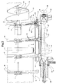
- FIG. 1 shows a preferred embodiment of the inventive device.
- This comprises a transport device 1 with a guided in a conveyor rail 26 conveyor chain (not shown).
- the conveyor chain contains a plurality of transport grippers 7 arranged one behind the other at uniform intervals, each holding at least one printed product 6 in a clamping manner via its fixed edge 10.
- the transport grippers 7 each have two clamping jaws 8a, 8b which are movable relative to one another from an open position into a closed position and vice versa and which clamp the printed product 6 in the closed position.
- the transport grippers 7 are mounted on the conveyor chain, which move them in a conveying direction F.
- the printed products 6 are held in each case hanging over their transverse to the conveying direction F fixed edge 10.
- the printed product 6 exists in each case from at least two, preferably more than two sheets or sides, which are held together by the fixed edge 10.
- the printed product 6 furthermore has a first and a second side edge region 24, 25 as well as a front edge region 9 lying opposite the fixed edge 10.
- the device further includes a arranged below the conveyor 1 support means 4 with a peripheral around pulleys 11 support belt 12.
- the support belt 12 forms for the opposite the fixed edge 10 front edge portions 9 a support surface.
- the support belt 12 is moved in the support surface in the conveying direction F and serves to support and guide the front edge region 9 of the supplied printed products 6 in the conveying direction F. This is done by the support belt 12 is arranged and moved relative to the printed products 6 so that the front edge region 9 of the respective printed product 6 the support band 12 on or rests and is bent in the conveying direction F against the front.
- the printing product 6 with the stabilized and with respect to the adjacent printed products 6 safely spaced, leading edge is fed from the support means in a subsequent conveying direction F opening unit 2 or passed.
- the opening unit 2 is likewise arranged below the transport device 1 and laterally from the conveyed printed products 6.
- the opening unit 2 includes a via a corresponding bearing 38 in the direction of rotation D rotatably mounted about a rotational axis 29 rotary body 36. To said axis of rotation 29 (see also FIG. 2 ), a helical opening channel 14 is arranged.
- the opening channel 14 includes two spaced-apart channel walls 22a, 22b between which a channel bottom 27 is arranged.
- the opening channel 14 is open radially outward and limited to the axis of rotation 29 through the channel bottom 27.
- the rotary body 36 includes in the conveying direction F viewed in front of the opening channel 14, a channel inlet wall 13, to which the corresponding side edge portion 24 of the printed product 6 from the support means 4 ago Coming approached. About the rotational movement of the rotary body 36 and thus also the channel inlet wall 13 and the opening channel 14 of the side edge portion 24 is inserted into the opening channel 14. The rotary body 36 screws each case between two hanging printed products 6, so that the printed products 6 and the free side edge portions 24 are guided in the opening channel 14.
- the channel inlet wall 13 goes into a side wall 22a, 22b of the opening channel. Since the opening channel is formed helically, the side edge portion 24 is carried in the rotating opening channel 14 in the conveying direction F.
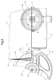
- the opening unit 2 also has blown air supply means 5, via which blown air 21 is fed into the opening channel 14.
- the blown air 21 is fed to the rotary body 36 via an external blown air line 37, which opens into an axial blower air feed line 28 lying in the axis of rotation 29 of the rotary body 36.
- the axial blast air supply line 28 has an end portion in the form of a tubular blast air chamber 47.
- the tubular blast air chamber 47 contains one or more axially aligned stomate openings 30, via which the blast air is guided into the opening channel 14.
- the channel bottom 27 of the opening channel 14 also contains one or more blown air passages 20 through which the blown air 21 supplied through the gap opening 30 is fed into the opening channel 14.
- an annular gap 31 is formed between the channel bottom 27 and the rotary body 36 and the gap opening 30 and the tubular blast air chamber 47. This is necessary because the rotary body 36 rotates with the opening channel 14 with respect to the tubular blast air chamber 47.
- the rotary body 36 with the opening channel 14 is rotatably supported about a rigidly mounted base body containing the Blas Kunststoffzuschreib Gustav 28 with the tubular Blas Kunststoffhunt 47.
- the gap opening 30 of the tubular blast air chamber 47 and the Blas Kunststoff malées 20 of the rotatably guided channel bottom 27 move when rotating the rotary body relative to each other. If the blown air passage 20 is now a gap opening arranged continuously in the channel bottom 27 in the longitudinal direction of the opening channel 14, a continuous blown air flow 21 is generated, which moves in the conveying direction together with the printed product 6 through the rotary movement of the helical opening channel 14. If the blown air passages 20 are rows of holes arranged along the opening channel 14 in the channel bottom 27, a modulated blown air stream 21 acts on the moving printed product 6.
- the blast air 21 thus flows radially out of the channel bottom 27 and parallel to the leaf surfaces of the printed product between the individual sheets and spreads them apart.
- the air cushion formed between the sheets 18 by the blowing air 21 lead to a thickening of the printed product 6 in the guided side edge region 24, which now fills the entire channel width.
- the rotary body 36 further includes an opening member 14 arranged in the opening element in the form of an opening wedge 15 which rotates according to the rotary body and moves through this rotational movement between the leaves 18 of the fluffed side edge portion 24 and this opens as soon as the conveyed in the conveying direction F printed product 6 at the location of the opening wedge 15 arrives.
- the opened printed product 6 now has a first and second product part 33, 34, which in each case comprises a plurality of sheets 18.
- the opened printed product 6 is then led out of the opening channel 14 towards the end of the rotary body 36 or the helical opening channel 14, with an open-holding element 39 likewise arranged on the rotary body 36 ensuring that the printed product 6 remains open.
- a hold-open device 3 in the form of a rotatable in a direction of rotation E about a rotation axis 40 Wendelschlange 19.
- the helical coil 19 is arranged laterally offset from the rotary body 36 and synchronized to the latter, that a retaining wedge 23 pierces the Wendelschlange 19 in the opened printed product 6 before it completely leaves the rotary body 36 and the helical opening channel 14 and thus the hold-open element 39.
- the opened printed product 6 is further accompanied by the rotating spiral coil 19 in the open position in the conveying direction F while being kept open.
- the printing products 6 are continuously conveyed during the opening process described above by the transport device 1, wherein the helical formation of the opening channel 14 and the helical formation of the hold-open device 19 ensure by their helical rotary motion that the printed product also at its in the opening channel 14 and in the helical coil 19 guided side edge region 24 is carried in the conveying direction F.
- the rotational speed of the rotating body 36 and the helical coil 19 is synchronized with the conveying speed of the conveying device 1 as a function of the pitch of the helix of the elements 14, 19 described. In this way, the products can be opened during their conveying in a continuous process, whereby more time is available to open the printed products or whereby the conveying speed can be increased.
- a supporting device 4 with its support belt 12 revolving around a front deflecting roller 11 is arranged laterally offset in front of the opening unit 2 or in front of its rotary body 36.
- the support belt 12 supports the front edge region 9 in the manner already described while the opening channel 14 of the rotary body 36, a first side edge portion 24 of the printed product 6 leads.
- the printed product 6 is supported both with its front edge region 9 by the support belt 12 and guided with its first side edge region 24 through the opening channel 14.
- FIG. 3 shows a printed product 6 in the transfer zone 32 between the opening unit 2 and the hold-open 3.
- the guided with a free side edge portion 24 in the opening channel 14 printed product 6 is characterized by the by the rotational movement of the rotary body 36 between the leaves of the printed product 6 entering opening wedge 15 as already described opened and forms a first and second product part 33, 34.
- the spiral coil 19 of the hold-open device 3 moves into the opened printed product 6, and even before it has left the opening unit 2 and thus the effective range of the opening wedge 15.
- the printed product 6 thus leaves the effective range of the opening wedge 15 only when a first helical loop 35 is retracted between the product parts 33, 34.
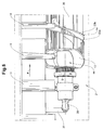
- FIG. 4 how out FIG. 4 is particularly well visible, the opening unit 2 and its rotary body 36 at its front end region (viewed in the conveying direction F) an inlet region 44 with a channel inlet wall 13.
- the printed product 6 is guided with its first side edge region 24 into the inlet region 44, which forms a funnel-shaped constriction and merges at its narrowest point into the opening channel 14.
- the channel inlet wall 13 forms a wall of the inlet funnel and merges into a first channel wall 22a.
- the other wall of the inlet funnel merges into the second channel wall 22b.
- the helically guided around the rotary body 36 opening channel 14 has towards the end of the rotating body (viewed in the conveying direction F) on an outlet region 45, in which the first side edge region 24 of the printed product 6 leaves the opening channel 14 again.
- the opening wedge 15 is arranged, which divides the fluffed printed product 6 into two product parts 33, 34 (see also FIG. 5 ).
- a distance control device 41 is arranged in front of the opening wedge 15 (viewed in the conveying direction F). This has first and second, arranged in the opening channel 14, and spaced-apart spacer strips 43a, 43b.
- the spacer strips 43a, 43b are arranged laterally on the channel walls 22a, 22b and serve to adjust the channel width, ie in particular the narrowing of the opening channel 14 before the opening of the printed product 6.
- the spacer strips 43a, 43b thus extend to the front edge 46 of the opening wedge 15 and possibly beyond.
- the distance control device 41 serves to adapt the opening unit 2 to different thicknesses of the printed products 6, ie to printed products 6 having a different number of sheets or pages. The more sheets a printed product comprises, the wider the opening channel 14 before the opening wedge 15. The fewer sheets or pages the printed product 6 has, the narrower is the channel in front of the opening wedge.
- the spacer strips 43a, 43b can, as shown here, be provided in addition to the channel walls 22a, 22b. However, they may also be formed as movable parts of the channel walls 22a, 22b themselves (not shown).
- the adjusting elements may for example comprise adjusting screws 42a, 42b, by means of which the spacer strips 43a, 43b or the channel walls 22a, 22b for adjusting the channel width are variable.
- the spacer strips 43a, 43b can also be adjusted via adjusting elements, such as electrically via control means (not shown).
- FIG. 6 shows an enlarged section of the funnel-shaped inlet region 44 according to FIG. 4 which merges with the channel walls 22a, 22b in the adjoining, helically shaped opening channel 14.
- FIGS. 1 to 6 also shown embodiments for guiding, fluffing and opening the front edge portion 9 of the printed product 6 instead of the free side edge portions 24, 25 are suitable.
- the term "blown air" used in the exemplary embodiments shown should generally include a gas flow.
Landscapes
- Engineering & Computer Science (AREA)
- Mechanical Engineering (AREA)
- Discharge By Other Means (AREA)
- Labeling Devices (AREA)
- Feeding Of Articles By Means Other Than Belts Or Rollers (AREA)
- Making Paper Articles (AREA)
Applications Claiming Priority (1)
| Application Number | Priority Date | Filing Date | Title |
|---|---|---|---|
| CH00856/10A CH703248A1 (de) | 2010-05-31 | 2010-05-31 | Vorrichtung und verfahren zum öffnen von druckereiprodukten. |
Publications (3)
| Publication Number | Publication Date |
|---|---|
| EP2390210A2 true EP2390210A2 (fr) | 2011-11-30 |
| EP2390210A3 EP2390210A3 (fr) | 2013-07-31 |
| EP2390210B1 EP2390210B1 (fr) | 2014-09-17 |
Family
ID=44118515
Family Applications (1)
| Application Number | Title | Priority Date | Filing Date |
|---|---|---|---|
| EP11405259.0A Active EP2390210B1 (fr) | 2010-05-31 | 2011-05-19 | Dispositif et procédé d'ouverture de produits d'imprimerie |
Country Status (7)
| Country | Link |
|---|---|
| US (1) | US8376123B2 (fr) |
| EP (1) | EP2390210B1 (fr) |
| BR (1) | BRPI1102959A2 (fr) |
| CA (1) | CA2741803A1 (fr) |
| CH (1) | CH703248A1 (fr) |
| RU (1) | RU2553966C2 (fr) |
| ZA (1) | ZA201103971B (fr) |
Families Citing this family (1)
| Publication number | Priority date | Publication date | Assignee | Title |
|---|---|---|---|---|
| EP3233463B1 (fr) * | 2014-12-18 | 2019-09-04 | Better All Round Ltd | Procédé et appareil destinés à plier et à ouvrir des lingettes |
Citations (4)
| Publication number | Priority date | Publication date | Assignee | Title |
|---|---|---|---|---|
| EP0647582A1 (fr) | 1993-10-08 | 1995-04-12 | Ferag AG | Dispositif pour ouvrir et transporter des produits imprimés |
| EP0577964B1 (fr) | 1992-07-06 | 1996-03-06 | Ferag AG | Méthode et dispositif pour l'insertion des objets dans des produits compartant plusieurs feuilles, en particulier dans des produits imprimés |
| EP1090867B1 (fr) | 1999-10-08 | 2004-09-08 | Schur Packaging Systems A/S | Méthode et dispositif pour placer des encarts dans des couvertures en papier pliées |
| EP1908714B1 (fr) | 2006-10-06 | 2010-04-07 | Idab Wamac International AB | Dispositif pour l'ouverture de feuilles pliées pendant le transport |
Family Cites Families (8)
| Publication number | Priority date | Publication date | Assignee | Title |
|---|---|---|---|---|
| US5112036A (en) * | 1990-08-27 | 1992-05-12 | Graphic Management Associates, Inc. | Opener for folder printed products |
| DE59200946D1 (de) * | 1991-06-10 | 1995-01-26 | Ferag Ag | Verfahren und Vorrichtung zum Öffnen und auf eine sattelförmige Auflage Ablegen von gefalteten Druckereiprodukten. |
| EP0564812B1 (fr) * | 1992-04-06 | 1997-05-28 | Ferag AG | Procédé et dispositif pour ouvrir des produits d'imprimerie pliés |
| DE59302441D1 (de) * | 1992-12-04 | 1996-06-05 | Ferag Ag | Verfahren und Vorrichtung zum Oeffnen von gefalteten Druckereiprodukten |
| DK0831045T3 (da) * | 1996-09-06 | 2002-02-11 | Ferag Ag | Fremgangsmåde og anordning til åbning af bøjelige, flade produkter |
| DE59901612D1 (de) * | 1999-01-26 | 2002-07-11 | Grapha Holding Ag | Vorrichtung zum Oeffnen und Ablegen eines gefalzten Bogens auf eine laufende Transportvorrichtung |
| ATE409672T1 (de) * | 2004-04-22 | 2008-10-15 | Ferag Ag | Verfahren und vorrichtung zum bearbeiten von druckereiprodukten |
| EP1626004A1 (fr) * | 2004-07-15 | 2006-02-15 | CAVANNA S.p.A. | Dispositif et procédé pour former des groupes de produits dans des systèmes de convoyage, particulièrement pour machines automatiques d'emballage |
-
2010
- 2010-05-31 CH CH00856/10A patent/CH703248A1/de not_active Application Discontinuation
-
2011
- 2011-05-19 EP EP11405259.0A patent/EP2390210B1/fr active Active
- 2011-05-27 US US13/117,280 patent/US8376123B2/en active Active
- 2011-05-27 RU RU2011121315/12A patent/RU2553966C2/ru not_active IP Right Cessation
- 2011-05-30 CA CA2741803A patent/CA2741803A1/fr not_active Abandoned
- 2011-05-30 ZA ZA2011/03971A patent/ZA201103971B/en unknown
- 2011-05-30 BR BRPI1102959-5A patent/BRPI1102959A2/pt not_active IP Right Cessation
Patent Citations (4)
| Publication number | Priority date | Publication date | Assignee | Title |
|---|---|---|---|---|
| EP0577964B1 (fr) | 1992-07-06 | 1996-03-06 | Ferag AG | Méthode et dispositif pour l'insertion des objets dans des produits compartant plusieurs feuilles, en particulier dans des produits imprimés |
| EP0647582A1 (fr) | 1993-10-08 | 1995-04-12 | Ferag AG | Dispositif pour ouvrir et transporter des produits imprimés |
| EP1090867B1 (fr) | 1999-10-08 | 2004-09-08 | Schur Packaging Systems A/S | Méthode et dispositif pour placer des encarts dans des couvertures en papier pliées |
| EP1908714B1 (fr) | 2006-10-06 | 2010-04-07 | Idab Wamac International AB | Dispositif pour l'ouverture de feuilles pliées pendant le transport |
Also Published As
| Publication number | Publication date |
|---|---|
| CA2741803A1 (fr) | 2011-11-30 |
| US8376123B2 (en) | 2013-02-19 |
| ZA201103971B (en) | 2012-03-28 |
| US20110290618A1 (en) | 2011-12-01 |
| CH703248A1 (de) | 2011-12-15 |
| BRPI1102959A2 (pt) | 2013-11-19 |
| EP2390210B1 (fr) | 2014-09-17 |
| RU2011121315A (ru) | 2012-12-10 |
| RU2553966C2 (ru) | 2015-06-20 |
| AU2011202464A1 (en) | 2011-12-15 |
| EP2390210A3 (fr) | 2013-07-31 |
Similar Documents
| Publication | Publication Date | Title |
|---|---|---|
| EP0536514B1 (fr) | Procédé et dispositif pour insérer un produit imprimé dans un produit principal plié | |
| EP2288560B1 (fr) | Dispositif et procédé pour insérer des objets plats dans produits d'impression pliés | |
| EP0600216B1 (fr) | Procédé et dispositif pour ouvrir des produits d'imprimerie pliés | |
| EP2462043B1 (fr) | Unité de pliage et procédé pour plier un flux imbriqué de produits | |
| EP1351873B1 (fr) | Procede de traitement de produits d'imprimerie | |
| EP0854105A1 (fr) | Méthode et dispositif pour traiter des produits imprimes plats, comme des journaux, des magazines, et des parties de cela | |
| DE19611788A1 (de) | Anordnung zum Falzen von Bögen | |
| EP2390210B1 (fr) | Dispositif et procédé d'ouverture de produits d'imprimerie | |
| EP0681979A1 (fr) | Dispositif pour traiter des produits imprimés | |
| EP1547950B1 (fr) | Méthode et dispositif pour stabiliser et positionner des objets plats | |
| EP2265528B1 (fr) | Procédé et dispositif de transport de produits plats | |
| EP2678171B1 (fr) | Station et procédé d'insertion dans une enveloppe | |
| EP0686592B1 (fr) | Dispositif pour la production de produits d'imprimerie | |
| EP0169489A1 (fr) | Dispositif pour plier et transformer des imprimés | |
| EP2418164B1 (fr) | Procédé et dispositif d'assemblage de produits plats avec d'autres produits plats et dispositif de transport de produits plats, notamment de produits d'imprimerie | |
| EP1809557B1 (fr) | Procede et dispositif permettant d'inserer des objets plats dans des produits imprimes | |
| WO2011066665A1 (fr) | Procédé et dispositif pour dévier un flux d'objets plats flexibles | |
| EP2367745B1 (fr) | Dispositif et procédé de transfert d'objets plats flexibles | |
| EP3398891B1 (fr) | Dispositif de production de collections d'imprimés en forme de feuilles, et appareil correspondant de pliage de collections d'imprimés en forme de feuilles | |
| DE19623307A1 (de) | Vorrichtung zum Verarbeiten von Druckereiprodukten | |
| EP2275370B1 (fr) | Procédé et dispositif pour ouvrir des produits d'imprimerie | |
| EP1657199A1 (fr) | Système pour le traitement de produits plats, en particulier articles imprimés | |
| CH701213A1 (de) | Vorrichtung und Verfahren zum Verarbeiten von Druckereiprodukten mit zwei benachbarten Zuführstationen. | |
| EP3197801B1 (fr) | Dispositif et procédé de séparation de parties d'un produit à plusieurs parties | |
| WO2011014969A1 (fr) | Dispositif et procédé pour plier des produits d'impression |
Legal Events
| Date | Code | Title | Description |
|---|---|---|---|
| AK | Designated contracting states |
Kind code of ref document: A2 Designated state(s): AL AT BE BG CH CY CZ DE DK EE ES FI FR GB GR HR HU IE IS IT LI LT LU LV MC MK MT NL NO PL PT RO RS SE SI SK SM TR |
|
| AX | Request for extension of the european patent |
Extension state: BA ME |
|
| PUAI | Public reference made under article 153(3) epc to a published international application that has entered the european phase |
Free format text: ORIGINAL CODE: 0009012 |
|
| PUAL | Search report despatched |
Free format text: ORIGINAL CODE: 0009013 |
|
| AK | Designated contracting states |
Kind code of ref document: A3 Designated state(s): AL AT BE BG CH CY CZ DE DK EE ES FI FR GB GR HR HU IE IS IT LI LT LU LV MC MK MT NL NO PL PT RO RS SE SI SK SM TR |
|
| AX | Request for extension of the european patent |
Extension state: BA ME |
|
| RIC1 | Information provided on ipc code assigned before grant |
Ipc: B65H 5/30 20060101AFI20130627BHEP |
|
| 17P | Request for examination filed |
Effective date: 20131111 |
|
| RBV | Designated contracting states (corrected) |
Designated state(s): AL AT BE BG CH CY CZ DE DK EE ES FI FR GB GR HR HU IE IS IT LI LT LU LV MC MK MT NL NO PL PT RO RS SE SI SK SM TR |
|
| GRAP | Despatch of communication of intention to grant a patent |
Free format text: ORIGINAL CODE: EPIDOSNIGR1 |
|
| INTG | Intention to grant announced |
Effective date: 20140515 |
|
| GRAS | Grant fee paid |
Free format text: ORIGINAL CODE: EPIDOSNIGR3 |
|
| GRAA | (expected) grant |
Free format text: ORIGINAL CODE: 0009210 |
|
| AK | Designated contracting states |
Kind code of ref document: B1 Designated state(s): AL AT BE BG CH CY CZ DE DK EE ES FI FR GB GR HR HU IE IS IT LI LT LU LV MC MK MT NL NO PL PT RO RS SE SI SK SM TR |
|
| REG | Reference to a national code |
Ref country code: GB Ref legal event code: FG4D Free format text: NOT ENGLISH |
|
| REG | Reference to a national code |
Ref country code: CH Ref legal event code: EP |
|
| REG | Reference to a national code |
Ref country code: IE Ref legal event code: FG4D Free format text: LANGUAGE OF EP DOCUMENT: GERMAN |
|
| REG | Reference to a national code |
Ref country code: AT Ref legal event code: REF Ref document number: 687594 Country of ref document: AT Kind code of ref document: T Effective date: 20141015 Ref country code: CH Ref legal event code: NV Representative=s name: FREI PATENTANWALTSBUERO AG, CH |
|
| REG | Reference to a national code |
Ref country code: DE Ref legal event code: R096 Ref document number: 502011004396 Country of ref document: DE Effective date: 20141030 |
|
| REG | Reference to a national code |
Ref country code: SE Ref legal event code: TRGR |
|
| PG25 | Lapsed in a contracting state [announced via postgrant information from national office to epo] |
Ref country code: LT Free format text: LAPSE BECAUSE OF FAILURE TO SUBMIT A TRANSLATION OF THE DESCRIPTION OR TO PAY THE FEE WITHIN THE PRESCRIBED TIME-LIMIT Effective date: 20140917 Ref country code: FI Free format text: LAPSE BECAUSE OF FAILURE TO SUBMIT A TRANSLATION OF THE DESCRIPTION OR TO PAY THE FEE WITHIN THE PRESCRIBED TIME-LIMIT Effective date: 20140917 Ref country code: GR Free format text: LAPSE BECAUSE OF FAILURE TO SUBMIT A TRANSLATION OF THE DESCRIPTION OR TO PAY THE FEE WITHIN THE PRESCRIBED TIME-LIMIT Effective date: 20141218 Ref country code: NO Free format text: LAPSE BECAUSE OF FAILURE TO SUBMIT A TRANSLATION OF THE DESCRIPTION OR TO PAY THE FEE WITHIN THE PRESCRIBED TIME-LIMIT Effective date: 20141217 |
|
| REG | Reference to a national code |
Ref country code: NL Ref legal event code: VDEP Effective date: 20140917 |
|
| REG | Reference to a national code |
Ref country code: LT Ref legal event code: MG4D |
|
| PG25 | Lapsed in a contracting state [announced via postgrant information from national office to epo] |
Ref country code: CY Free format text: LAPSE BECAUSE OF FAILURE TO SUBMIT A TRANSLATION OF THE DESCRIPTION OR TO PAY THE FEE WITHIN THE PRESCRIBED TIME-LIMIT Effective date: 20140917 Ref country code: RS Free format text: LAPSE BECAUSE OF FAILURE TO SUBMIT A TRANSLATION OF THE DESCRIPTION OR TO PAY THE FEE WITHIN THE PRESCRIBED TIME-LIMIT Effective date: 20140917 Ref country code: HR Free format text: LAPSE BECAUSE OF FAILURE TO SUBMIT A TRANSLATION OF THE DESCRIPTION OR TO PAY THE FEE WITHIN THE PRESCRIBED TIME-LIMIT Effective date: 20140917 Ref country code: LV Free format text: LAPSE BECAUSE OF FAILURE TO SUBMIT A TRANSLATION OF THE DESCRIPTION OR TO PAY THE FEE WITHIN THE PRESCRIBED TIME-LIMIT Effective date: 20140917 |
|
| PG25 | Lapsed in a contracting state [announced via postgrant information from national office to epo] |
Ref country code: NL Free format text: LAPSE BECAUSE OF FAILURE TO SUBMIT A TRANSLATION OF THE DESCRIPTION OR TO PAY THE FEE WITHIN THE PRESCRIBED TIME-LIMIT Effective date: 20140917 |
|
| PG25 | Lapsed in a contracting state [announced via postgrant information from national office to epo] |
Ref country code: PT Free format text: LAPSE BECAUSE OF FAILURE TO SUBMIT A TRANSLATION OF THE DESCRIPTION OR TO PAY THE FEE WITHIN THE PRESCRIBED TIME-LIMIT Effective date: 20150119 Ref country code: ES Free format text: LAPSE BECAUSE OF FAILURE TO SUBMIT A TRANSLATION OF THE DESCRIPTION OR TO PAY THE FEE WITHIN THE PRESCRIBED TIME-LIMIT Effective date: 20140917 Ref country code: CZ Free format text: LAPSE BECAUSE OF FAILURE TO SUBMIT A TRANSLATION OF THE DESCRIPTION OR TO PAY THE FEE WITHIN THE PRESCRIBED TIME-LIMIT Effective date: 20140917 Ref country code: EE Free format text: LAPSE BECAUSE OF FAILURE TO SUBMIT A TRANSLATION OF THE DESCRIPTION OR TO PAY THE FEE WITHIN THE PRESCRIBED TIME-LIMIT Effective date: 20140917 Ref country code: IS Free format text: LAPSE BECAUSE OF FAILURE TO SUBMIT A TRANSLATION OF THE DESCRIPTION OR TO PAY THE FEE WITHIN THE PRESCRIBED TIME-LIMIT Effective date: 20150117 Ref country code: RO Free format text: LAPSE BECAUSE OF FAILURE TO SUBMIT A TRANSLATION OF THE DESCRIPTION OR TO PAY THE FEE WITHIN THE PRESCRIBED TIME-LIMIT Effective date: 20140917 Ref country code: SK Free format text: LAPSE BECAUSE OF FAILURE TO SUBMIT A TRANSLATION OF THE DESCRIPTION OR TO PAY THE FEE WITHIN THE PRESCRIBED TIME-LIMIT Effective date: 20140917 |
|
| PG25 | Lapsed in a contracting state [announced via postgrant information from national office to epo] |
Ref country code: PL Free format text: LAPSE BECAUSE OF FAILURE TO SUBMIT A TRANSLATION OF THE DESCRIPTION OR TO PAY THE FEE WITHIN THE PRESCRIBED TIME-LIMIT Effective date: 20140917 |
|
| REG | Reference to a national code |
Ref country code: DE Ref legal event code: R097 Ref document number: 502011004396 Country of ref document: DE |
|
| REG | Reference to a national code |
Ref country code: DE Ref legal event code: R082 Ref document number: 502011004396 Country of ref document: DE Representative=s name: PATENTANWAELTE UND RECHTSANWALT DR. WEISS, ARA, DE Ref country code: DE Ref legal event code: R082 Ref document number: 502011004396 Country of ref document: DE Representative=s name: PATENTANWAELTE UND RECHTSANWALT WEISS, ARAT & , DE |
|
| PLBE | No opposition filed within time limit |
Free format text: ORIGINAL CODE: 0009261 |
|
| STAA | Information on the status of an ep patent application or granted ep patent |
Free format text: STATUS: NO OPPOSITION FILED WITHIN TIME LIMIT |
|
| PG25 | Lapsed in a contracting state [announced via postgrant information from national office to epo] |
Ref country code: DK Free format text: LAPSE BECAUSE OF FAILURE TO SUBMIT A TRANSLATION OF THE DESCRIPTION OR TO PAY THE FEE WITHIN THE PRESCRIBED TIME-LIMIT Effective date: 20140917 |
|
| 26N | No opposition filed |
Effective date: 20150618 |
|
| PG25 | Lapsed in a contracting state [announced via postgrant information from national office to epo] |
Ref country code: SI Free format text: LAPSE BECAUSE OF FAILURE TO SUBMIT A TRANSLATION OF THE DESCRIPTION OR TO PAY THE FEE WITHIN THE PRESCRIBED TIME-LIMIT Effective date: 20140917 |
|
| GBPC | Gb: european patent ceased through non-payment of renewal fee |
Effective date: 20150519 |
|
| PG25 | Lapsed in a contracting state [announced via postgrant information from national office to epo] |
Ref country code: LU Free format text: LAPSE BECAUSE OF FAILURE TO SUBMIT A TRANSLATION OF THE DESCRIPTION OR TO PAY THE FEE WITHIN THE PRESCRIBED TIME-LIMIT Effective date: 20150519 Ref country code: MC Free format text: LAPSE BECAUSE OF FAILURE TO SUBMIT A TRANSLATION OF THE DESCRIPTION OR TO PAY THE FEE WITHIN THE PRESCRIBED TIME-LIMIT Effective date: 20140917 |
|
| REG | Reference to a national code |
Ref country code: IE Ref legal event code: MM4A |
|
| REG | Reference to a national code |
Ref country code: FR Ref legal event code: ST Effective date: 20160129 |
|
| PG25 | Lapsed in a contracting state [announced via postgrant information from national office to epo] |
Ref country code: IE Free format text: LAPSE BECAUSE OF NON-PAYMENT OF DUE FEES Effective date: 20150519 Ref country code: GB Free format text: LAPSE BECAUSE OF NON-PAYMENT OF DUE FEES Effective date: 20150519 |
|
| PG25 | Lapsed in a contracting state [announced via postgrant information from national office to epo] |
Ref country code: FR Free format text: LAPSE BECAUSE OF NON-PAYMENT OF DUE FEES Effective date: 20150601 |
|
| PG25 | Lapsed in a contracting state [announced via postgrant information from national office to epo] |
Ref country code: MT Free format text: LAPSE BECAUSE OF FAILURE TO SUBMIT A TRANSLATION OF THE DESCRIPTION OR TO PAY THE FEE WITHIN THE PRESCRIBED TIME-LIMIT Effective date: 20140917 |
|
| PG25 | Lapsed in a contracting state [announced via postgrant information from national office to epo] |
Ref country code: SM Free format text: LAPSE BECAUSE OF FAILURE TO SUBMIT A TRANSLATION OF THE DESCRIPTION OR TO PAY THE FEE WITHIN THE PRESCRIBED TIME-LIMIT Effective date: 20140917 Ref country code: BG Free format text: LAPSE BECAUSE OF FAILURE TO SUBMIT A TRANSLATION OF THE DESCRIPTION OR TO PAY THE FEE WITHIN THE PRESCRIBED TIME-LIMIT Effective date: 20140917 Ref country code: HU Free format text: LAPSE BECAUSE OF FAILURE TO SUBMIT A TRANSLATION OF THE DESCRIPTION OR TO PAY THE FEE WITHIN THE PRESCRIBED TIME-LIMIT; INVALID AB INITIO Effective date: 20110519 |
|
| REG | Reference to a national code |
Ref country code: AT Ref legal event code: MM01 Ref document number: 687594 Country of ref document: AT Kind code of ref document: T Effective date: 20160519 |
|
| PG25 | Lapsed in a contracting state [announced via postgrant information from national office to epo] |
Ref country code: BE Free format text: LAPSE BECAUSE OF NON-PAYMENT OF DUE FEES Effective date: 20150531 |
|
| PG25 | Lapsed in a contracting state [announced via postgrant information from national office to epo] |
Ref country code: AT Free format text: LAPSE BECAUSE OF NON-PAYMENT OF DUE FEES Effective date: 20160519 Ref country code: TR Free format text: LAPSE BECAUSE OF FAILURE TO SUBMIT A TRANSLATION OF THE DESCRIPTION OR TO PAY THE FEE WITHIN THE PRESCRIBED TIME-LIMIT Effective date: 20140917 |
|
| PG25 | Lapsed in a contracting state [announced via postgrant information from national office to epo] |
Ref country code: MK Free format text: LAPSE BECAUSE OF FAILURE TO SUBMIT A TRANSLATION OF THE DESCRIPTION OR TO PAY THE FEE WITHIN THE PRESCRIBED TIME-LIMIT Effective date: 20140917 |
|
| PG25 | Lapsed in a contracting state [announced via postgrant information from national office to epo] |
Ref country code: AL Free format text: LAPSE BECAUSE OF FAILURE TO SUBMIT A TRANSLATION OF THE DESCRIPTION OR TO PAY THE FEE WITHIN THE PRESCRIBED TIME-LIMIT Effective date: 20140917 |
|
| PGFP | Annual fee paid to national office [announced via postgrant information from national office to epo] |
Ref country code: SE Payment date: 20210519 Year of fee payment: 11 |
|
| PGFP | Annual fee paid to national office [announced via postgrant information from national office to epo] |
Ref country code: IT Payment date: 20220524 Year of fee payment: 12 |
|
| REG | Reference to a national code |
Ref country code: SE Ref legal event code: EUG |
|
| PG25 | Lapsed in a contracting state [announced via postgrant information from national office to epo] |
Ref country code: SE Free format text: LAPSE BECAUSE OF NON-PAYMENT OF DUE FEES Effective date: 20220520 |
|
| P01 | Opt-out of the competence of the unified patent court (upc) registered |
Effective date: 20230526 |
|
| PGFP | Annual fee paid to national office [announced via postgrant information from national office to epo] |
Ref country code: DE Payment date: 20230519 Year of fee payment: 13 Ref country code: CH Payment date: 20230602 Year of fee payment: 13 |
|
| PG25 | Lapsed in a contracting state [announced via postgrant information from national office to epo] |
Ref country code: IT Free format text: LAPSE BECAUSE OF NON-PAYMENT OF DUE FEES Effective date: 20230519 |