EP2390123B2 - Assembly for controlling at least two air flows - Google Patents
Assembly for controlling at least two air flows Download PDFInfo
- Publication number
- EP2390123B2 EP2390123B2 EP11164362.3A EP11164362A EP2390123B2 EP 2390123 B2 EP2390123 B2 EP 2390123B2 EP 11164362 A EP11164362 A EP 11164362A EP 2390123 B2 EP2390123 B2 EP 2390123B2
- Authority
- EP
- European Patent Office
- Prior art keywords
- flap
- air
- drum
- flaps
- opening
- Prior art date
- Legal status (The legal status is an assumption and is not a legal conclusion. Google has not performed a legal analysis and makes no representation as to the accuracy of the status listed.)
- Not-in-force
Links
Images


Classifications
-
- B—PERFORMING OPERATIONS; TRANSPORTING
- B60—VEHICLES IN GENERAL
- B60H—ARRANGEMENTS OF HEATING, COOLING, VENTILATING OR OTHER AIR-TREATING DEVICES SPECIALLY ADAPTED FOR PASSENGER OR GOODS SPACES OF VEHICLES
- B60H1/00—Heating, cooling or ventilating [HVAC] devices
- B60H1/00642—Control systems or circuits; Control members or indication devices for heating, cooling or ventilating devices
- B60H1/00664—Construction or arrangement of damper doors
- B60H1/00671—Damper doors moved by rotation; Grilles
-
- B—PERFORMING OPERATIONS; TRANSPORTING
- B60—VEHICLES IN GENERAL
- B60H—ARRANGEMENTS OF HEATING, COOLING, VENTILATING OR OTHER AIR-TREATING DEVICES SPECIALLY ADAPTED FOR PASSENGER OR GOODS SPACES OF VEHICLES
- B60H1/00—Heating, cooling or ventilating [HVAC] devices
- B60H1/00642—Control systems or circuits; Control members or indication devices for heating, cooling or ventilating devices
- B60H1/00814—Control systems or circuits characterised by their output, for controlling particular components of the heating, cooling or ventilating installation
- B60H1/00821—Control systems or circuits characterised by their output, for controlling particular components of the heating, cooling or ventilating installation the components being ventilating, air admitting or air distributing devices
- B60H1/00835—Damper doors, e.g. position control
- B60H1/00842—Damper doors, e.g. position control the system comprising a plurality of damper doors; Air distribution between several outlets
Definitions
- the invention relates to a system for controlling at least two air streams by means of at least one leg flap and at least one drum flap.
- Such systems for controlling at least two air streams are usually provided in air conditioning systems and can serve, for example, to control a defrost air flow and a diffused air flow.
- air conditioning systems can serve, for example, to control a defrost air flow and a diffused air flow.
- separate flaps or kinematics are provided for the flaps according to the state of the art, so that the flaps can be controlled individually as desired.
- document FR-A-2778151 discloses a system according to the first part of claim 1.
- Such a common drive reduces the structural complexity for controlling the two flaps significantly and yet allows to control two air streams independently of each other by means of the two flaps or to provide different openings for the air streams by means of the flaps available.
- the flaps are advantageously designed so that they each provide differing large openings for the respective air streams in the majority of the tractionable by means of the drive angular position.
- the two air streams can be influenced to varying degrees, although the two flaps are moved with the same angular positions or are in the same angular positions.
- the drum flap on at least two open, air-conducting areas. These areas may be, for example, more or less opposite and thus depending on the angular position of the drum flap offer a different sized total opening for the drum flap flowing through the air flow.
- the opening degree of the drum flap can be varied depending on their angular position and possibly deviate from the opening degree of the leg flap.
- the open, air-conducting areas of the drum flap melklappe are designed and arranged so that at the various angular positions of the two flaps of the opening degree of the drum flap and the Opening degree of the leg flap each differ from each other.
- it allows the system by means of the two flaps to control the two air streams to be controlled differently, although a common drive is provided for the two flaps and the two flaps are each in the same angular position.
- the opening angle of the two flaps is chosen to be the same size and is preferably about 75 degrees.
- a deviation of the opening angle of +/- 10 degrees is also considered to be about the same in this context.
- angles between an air inlet and an air outlet opening of the drum flap are advantageously advantageously greater than half the opening angle of the leg flaps to be selected, since in this way as many opening states of the flaps can be realized.
- the flaps can advantageously be arranged on a common shaft, as is provided according to a further embodiment of the invention.
- the flaps are designed and arranged so that in a 0 degree position both flaps are closed, in a 75 degree position, the leg flap fully open and the drum flap is closed and that in a 150 degree position the leg flap is closed and the drum flap is open. Between these angular positions then corresponding transition positions of the opening degrees of the flaps arise. For example, the leg flap is partially opened in a position between 0 and 75 degrees. Similarly, the drum door is partially opened in a position between 75 degrees and 150 degrees,
- the system of the invention provides a desired and possibly different control of two air streams with the least possible structural complexity.
- a system is advantageously used in a vehicle air conditioner, for example for controlling a defrost and a diffuse air flow, for the control of which separate drives would be required without the use of the system according to the invention.
- FIG. 4 schematically shows an air conditioning case of an air conditioner with built-in elements.
- Fig. 1 shows a system according to the invention for controlling at least two air streams by means of a leg flap and a drum flap.
- a leg flap and a drum flap In the illustration according to Fig. 1 These two flaps are each shown in sectional view and for four different angular positions.
- Fig. 1A shows on the left an air duct 1, in which a leg flap 2 is shown.
- the representation according to Fig. 1A shows the leg flap 2 in its rest position in which it is closed, so that by the air duct 1 to be led, flowing in the direction of arrow air flow, the throttle valve 2 can not happen.
- Fig. 1A also shows on the right a drum flap 3, which has closed areas 4 and 5, which are approximately opposite. Through these areas, no air can be guided. Furthermore, the drum flap 3 has air-conducting regions 6 and 7, which are also approximately opposite one another and through which, in contrast to the regions 4 and 5, air can be guided.
- the drum cap 3 is arranged in an air duct, of which in the Fig. 1 an inlet opening 8 and an outlet opening 9 are indicated.
- FIG. 1A Furthermore, the opening angles ⁇ and ⁇ are indicated.
- the sectional view of the leg flap 2 shows the opening angle ⁇ , which is the opening angle between the closed and the fully opened state of the leg flap 2, as in accordance with Fig. 2B is shown, indicates.
- the opening angle ⁇ of the drum flap 3 is indicated.
- FIG. 1A shows the leg flap 2 and the drum flap 3 in its rest position; this position is referred to below as 0 degrees angular position.
- the leg flap 2 is closed.
- the drum flap 3 is positioned so that the closed area 5 obstructs the outlet opening 9, so that the drum flap 3 as a whole blocks the flow of air.
- the leg flap 2 and the drum flap 3 are a -in the FIG. 1 not indicated - manner jointly driven so that they are each moved by the same angular position.
- Fig. 1C shows a representation corresponding to the Fig. 1A and 1B However, wherein both the leg flap 2 as well as the drum flap 3 were further rotated in a clockwise direction and opposite to the rest position as shown in FIG Fig. 1A in an angular position of about 112.5 degrees.
- FIG. 1C shows that the leg flap 2 is no longer fully open, but now brakes the air duct 1 flowing through the air duct and compared to the fully open position has approximately an opening ratio of only 50%.
- the drum flap 3 is rotated by the same angle value relative to the rest position.
- the air-permeable areas 6 and 7 partially cover the air intake opening 8 and the air outlet opening 9, so that air can circulate between them in some areas.
- the opening ratio is about 50% compared to the fully open position.
- Fig. 1D shows a representation corresponding to the Fig. 1A-C , but in a 150 degree angular position relative to the rest position according to Fig. 1A ,
- FIG. 1D shows that the Schenkolklappe has now been rotated clockwise so far that it closes again.
- the drum flap 3 has been compared with the illustration according to Fig. 1A rotated by the same angle value.
- the air-permeable areas 7 and 8 now lie in the area of the air inlet opening 8 and the air outlet opening 9, so that the air flow can pass through the drum flap 3 substantially unhindered, which corresponds to an opening degree of 100%.
- Fig. 1 shows the two flaps in four exemplary, different angular positions.
- the flaps 2 and 3 can be placed in any position between these in the Fig. 1 shown angular positions are driven, in which case the opening ratios change accordingly.
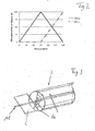
- Fig. 2 indicated in the form of a diagram.
- Fig. 2 is plotted in the form of a diagram, the opening angle of 0 to 100% above the angular position of the flaps 2 and 3 from 0 to 150 degrees.
- a solid line is entered, the opening ratio of the leg flap 2 of the system according to Fig. 1 suggests.
- a dot-dash line indicates the opening ratio of the drum flap 3 of the system according to Fig. 1 at
- FIG. 2 shows that with the angular position of 0 degrees both flaps 2 and 3 closed are, the ⁇ ffungshunt for both valves is therefore 0%. This corresponds to the illustration according to Fig. 1A ,
- Fig. 2 further shows that at an angular position of 75 degrees, the leg flap is fully open, so their aperture ratio is 100%. In this angular position, the drum flap 3 is still closed, so that its opening ratio is 0%. This corresponds to the position of the flaps 2 and 3 according to Fig. 1B ,
- Fig. 2 shows that for angular positions between 0 degrees and 75 degrees, the opening ratio of the leg flap 2 increases in accordance with the set angular position of 0% to 100%, so that controlled by changing the angular position of the leg flap 2 in this area, the Heilleitstrom flowing through it between 0 and 100% can be.
- the drum flap 3 remains completely closed in this angular range
- Fig. 2 shows further that at an angle of about 112.5 degrees both flaps 2 and 3 have an aperture ratio of about 50%. This corresponds to the illustration according to Fig. 1C ,
- Fig. 2 further indicates that at a final angular position of 150 degrees, the leg flap 2 in turn fully closed and the drum door 3 is fully open. This corresponds to the illustration according to Fig. 1D ,
- the opening ratio of the leg flap 2 changes from 100% to 0%;
- the opening ratio of the drum door 3 in this range changes from 0% to 100%.
- the representation according to Fig. 2 shows that with appropriate choice of angular position in the range of 75 degrees to 150 degrees both air streams can be continuously influenced in the desired manner, so that can be continuously selected between complete closing of the respective flap and full opening of the flap with any intermediate positions.
- the system according to the invention makes it possible to control two air flows by means of the leg flap 2 and the drum flap 3 continuously and in the desired manner with opening degrees differing from one another, if desired, although both flaps are moved by means of a common drive.
- This also indicates the Fig. 2 which shows that the opening ratios of both flaps differ depending on the angular position and are also different among each other in almost all angular positions.
- Such a system for controlling two air streams can advantageously be used for example in a vehicle for an air conditioner, in which, for example, a diffuse air flow and a defrost air flow are to be controlled.
- a common control is provided for both valves provided for this purpose.
- a defrost airflow can be controlled by means of the leg flap 2 and a diffused airflow by means of the drum flap 3.
- FIG. 3 schematically shows an arrangement of the drum flap 3 with a leg flap 2 preferably for the defrost and / or Diffusauslasskanal with a common shaft 11.
- the openings 10 of the drum door 3 can be seen.
- FIG. 4 schematically shows an air conditioner 12 with housing 13, in which an evaporator 14, a radiator 15 is arranged.
- the flow path through the evaporator is indicated at 16.
- a mixing flap 17 is provided, which is mixed in the mixing chamber 20.
- outlets the Defrostdüse 21 are shown with leg flap 2.
- nozzles 22, 23 and 24 are shown for the exit of the side nozzles, the center nozzles and the footwell exit.
Description
Die Erfindung betrifft eine Anlage zur Steuerung wenigstens zweier Luftströme mittels wenigstens einer Schenkelklappe und wenigstens einer Trommelklappe.The invention relates to a system for controlling at least two air streams by means of at least one leg flap and at least one drum flap.
Derartige Anlagen zur Steuerung wenigstens zweier Luftströme sind meist in Klimaanlagen vorgesehen und können beispielsweise dazu dienen, einen Defrost-Luftstrom und einen Diffus-Luftstrom zu steuern. Dabei sind für die Klappen nach dem Stande der Technik jeweils eigene Antriebe oder Kinematiken vorgesehen, so dass die Klappen individuell wie gewünscht gesteuert werden können.Such systems for controlling at least two air streams are usually provided in air conditioning systems and can serve, for example, to control a defrost air flow and a diffused air flow. In this case, separate flaps or kinematics are provided for the flaps according to the state of the art, so that the flaps can be controlled individually as desired.
Dokument
Es ist Aufgabe der Erfindung, eine Anlage zur Steuerung wenigstens zweier Luftströme mittels wenigstens einer Schenkelklappe und wenigstens einer Trommelklappe anzugeben, welche es bei möglichst geringem baulichen Aufwand gestattet, für die Luftströme jeweils Öffnungen gewünschter Größe zu bieten, die gegebenenfalls auch voneinander abweichen können.It is an object of the invention to provide a system for controlling at least two air streams by means of at least one leg flap and at least one drum flap, which allows it with minimal structural complexity to provide for the air streams each openings of desired size, which may also differ from each other.
Diese Aufgabe ist für eine Anlage der eingangs genannten Art durch die Merkmalen des kennzeichnenden Teil des Anspruchs 1 gelöst.This object is achieved by a system of the type mentioned by the features of the characterizing part of claim 1.
Ein derartiger gemeinsamer Antrieb vermindert den baulichen Aufwand zur Steuerung der beiden Klappen erheblich und gestattet es dennoch, zwei Luftströme unabhängig voneinander mittels der beiden Klappen zu steuern bzw. für die Luftströme unterschiedliche Öffnungen mittels der Klappen zur Verfügung zu stellen.Such a common drive reduces the structural complexity for controlling the two flaps significantly and yet allows to control two air streams independently of each other by means of the two flaps or to provide different openings for the air streams by means of the flaps available.
Dabei sind die Klappen, wie gemäß einer Ausgestaltung der Erfindung vorgesehen ist, vorteilhafterweise so ausgebildet, dass sie in der Mehrzahl der mittels des Antriebs anfahrbaren Winkelposition jeweils differierend große Öffnungen für die jeweiligen Luftströme bieten. Somit können die beiden Luftströme in jeweils unterschiedlichem Maße beeinflusst werden, obwohl die beiden Klappen mit jeweils gleichen Winkelpositionen bewegt werden bzw. sich in jeweils gleichen Winkelpositionen befinden.In this case, the flaps, as provided according to one embodiment of the invention, are advantageously designed so that they each provide differing large openings for the respective air streams in the majority of the tractionable by means of the drive angular position. Thus, the two air streams can be influenced to varying degrees, although the two flaps are moved with the same angular positions or are in the same angular positions.
Nach der Erfindung weist die Trommelklappe wenigstens zwei offene, luftführende Bereiche auf. Diese Bereiche können sich beispielsweise mehr oder weniger gegenüberliegen und somit je nach Winkelposition der Trommelklappe eine verschieden große Gesamtöffnung für den die Trommelklappe durchströmenden Luftstrom bieten. Somit kann der Öffnungsgrad der Trommelklappe in Abhängigkeit ihrer Winkelstellung variiert werden und ggf. von dem Öffnungsgrad der Schenkelklappe abweichen.According to the invention, the drum flap on at least two open, air-conducting areas. These areas may be, for example, more or less opposite and thus depending on the angular position of the drum flap offer a different sized total opening for the drum flap flowing through the air flow. Thus, the opening degree of the drum flap can be varied depending on their angular position and possibly deviate from the opening degree of the leg flap.
Um die die beiden Klappen durchströmenden Luftströme jeweils in verschiedener Weise steuern zu können, ist gemäß der Erfindung vorgesehen, dass die offenen, luftführenden Bereiche der Trommelklappe melklappe so ausgebildet und angeordnet sind, dass bei den verschiedenen Winkelstellungen der beiden Klappen der Öffnungsgrad der Trommelklappe und der Öffnungsgrad der Schenkelklappe jeweils Voneinander abweichen. Somit gestattet es die Anlage, mittels der beiden Klappen die beiden zu steuernden Luftströme jeweils verschieden zu steuern, obwohl für die beiden Klappen ein gemeinsamer Antrieb vorgesehen ist und die beiden Klappen sich jeweils in gleicher Winkelposition befinden.In order to control the two flaps flowing through the air streams in different ways, it is provided according to the invention that the open, air-conducting areas of the drum flap melklappe are designed and arranged so that at the various angular positions of the two flaps of the opening degree of the drum flap and the Opening degree of the leg flap each differ from each other. Thus, it allows the system by means of the two flaps to control the two air streams to be controlled differently, although a common drive is provided for the two flaps and the two flaps are each in the same angular position.
Vorzugsweise ist, wie gemäß einer weiteren Ausgestaltung der Erfindung vorgesehen ist, der Öffnungswinkel der beiden Klappen gleich groß gewählt und beträgt vorzugsweise etwa 75 Grad. Eine Abweichung der Öffnungswinkel von +/-10 Grad wird in diesem Zusammenhang ebenfalls als etwa gleich groß erachtet.Preferably, as provided according to a further embodiment of the invention, the opening angle of the two flaps is chosen to be the same size and is preferably about 75 degrees. A deviation of the opening angle of +/- 10 degrees is also considered to be about the same in this context.
Dabei sind die Winkel zwischen einer Lufteinlass- und einer Luftauslassöffnung der Trommelklappe weiter vorteilhaft größer als der halbe Öffnungswinkel der Schenkelklappen zu wählen, da auf diese Weise möglichst viele Öffnungszustände der Klappen verwirklicht werden können.In this case, the angles between an air inlet and an air outlet opening of the drum flap are advantageously advantageously greater than half the opening angle of the leg flaps to be selected, since in this way as many opening states of the flaps can be realized.
Für eine weitere Vereinfachung des Aufbaus können die Klappen vorteilhaft, wie gemäß einer weiteren Ausgestaltung der Erfindung vorgesehen ist, auf einer gemeinsamen Welle angeordnet sein.For a further simplification of the construction, the flaps can advantageously be arranged on a common shaft, as is provided according to a further embodiment of the invention.
Gemäß einer weiteren Ausgestaltung der Erfindung ist vorgesehen, dass die Klappen so ausgebildet und angeordnet sind, dass in einer 0 Grad Stellung beide Klappen geschlossen sind, in einer 75 Grad Stellung die Schenkelklappe voll geöffnet und die Trommelklappe geschlossen ist und dass in einer 150 Grad Stellung die Schenkelklappe geschlossen und die Trommelklappe geöffnet ist. Zwischen diesen Winkelpositionen ergeben sich dann entsprechende Übergangspositionen der Öffnungsgrade der Klappen. So ist beispielsweise die Schenkelklappe in einer Stellung zwischen 0 und 75 Grad teilweise geöffnet. In entsprechender Weise ist die Trommelklappe in einer Stellung zwischen 75 Grad und 150 Grad teilweise geöffnet,According to a further embodiment of the invention it is provided that the flaps are designed and arranged so that in a 0 degree position both flaps are closed, in a 75 degree position, the leg flap fully open and the drum flap is closed and that in a 150 degree position the leg flap is closed and the drum flap is open. Between these angular positions then corresponding transition positions of the opening degrees of the flaps arise. For example, the leg flap is partially opened in a position between 0 and 75 degrees. Similarly, the drum door is partially opened in a position between 75 degrees and 150 degrees,
Auf diese Weise ist trotz gemeinsamer Steuerung der beiden Klappen eine differierende Steuerung der beiden Luftströme möglich.In this way, despite the common control of the two flaps, a differential control of the two air streams is possible.
Die erfindungsgemäße Anlage bietet eine gewünschte und gegebenenfalls differierende Steuerung zweier Luftströme bei möglichst geringem baulichen Aufwand. Eine derartige Anlage ist vorteilhaft in einem Fahrzeugklimagerät einsetzbar, beispielsweise zur Steuerung eines Defrost- und eines Diffus-Luftstroms, für deren Steuerung ohne Einsatz der erfindungsgemäßen Anlage gesonderte Antriebe erforderlich wären.The system of the invention provides a desired and possibly different control of two air streams with the least possible structural complexity. Such a system is advantageously used in a vehicle air conditioner, for example for controlling a defrost and a diffuse air flow, for the control of which separate drives would be required without the use of the system according to the invention.
Nachfolgend wird ein Ausführungsbeispiel anhand der Zeichnungen näher erläutert. Es zeigen:
-
Fig, 1 eine schematische Darstellung einer erfindungsgemäßen Anlage zur Steuerung zweier Luftströme mit einer Schenkelklappe und einer Trommelklappe, jeweils in Schnittdarstellung und -
Fig. 2 ein Diagramm der Öffnungsgrade der beiden Klappen gemäßFig. 1 in den verschiedenen Winkelstellungen. -
Fig. 3 zeigt schematisch die Anordnung der Trommelklappe und der Schenkelklappe auf einer Welle.
-
Fig, 1 a schematic representation of a system according to the invention for controlling two air streams with a leg flap and a drum flap, respectively in a sectional view and -
Fig. 2 a diagram of the degrees of opening of the two valves according toFig. 1 in the different angular positions. -
Fig. 3 schematically shows the arrangement of the drum flap and the leg flap on a shaft.
Die
Die Trommelkappe 3 ist in einem Luftleitkanal angeordnet, von dem in der
In
Die Darstellung gemäß
In dieser Stellung ist die Schenkelklappe 2 geschlossen. In entsprechender Weise ist die Trommelklappe 3 so positioniert, dass der geschlossene Bereich 5 die Auslassöffnung 9 versperrt, so dass die Trommelklappe 3 insgesamt den Luftstrom sperrt.In this position, the
Die Schenkelklappe 2 sowie die Trommelklappe 3 sind einer -in der
Dies wird anhand der Darstellung gemäß
Die Darstellung gemäß
In der Darstellung gemäß
Die Darstellung gemäß
In
In dem Diagramm ist eine durchgezogene Linie eingetragen, die das Öffnungsverhältnis der Schenkelklappe 2 der Anlage gemäß
Das Diagramm gemäß
In dem Winkelstellungsbereich von 75 Grad bis 150 Grad verändert sich das Öffnungsverhältnis der Schenkelklappe 2 von 100% auf 0%; hingegen verändert sich das Öffnungsverhältnis der Trommelklappe 3 in diesem Bereich von 0% auf 100%. Die Darstellung gemäß
Somit ermöglicht es die erfindungsgemäße Anlage, zwei Luftströme mittels der Schenkelklappe 2 und der Trommelklappe 3 jeweils kontinuierlich und in gewünschter Weise mit, soweit gewünscht, voneinander abweichenden Öffnungsgraden zu steuern, obwohl beide Klappen mittels eines gemeinsamen Antriebs bewegt werden. Dies deutet auch die
Eine derartige Anlage zur Steuerung zweier Luftströme kann vorteilhaft beispielsweise in einem Fahrzeug für ein Klimagerät eingesetzt werden, bei der beispielsweise ein Diffus-Luftstrom sowie ein Defrost-Luftstrom zu steuern sind. Um den wirtschaftlichen Aufwand gering zu halten, ist für beide dafür vorgesehene Klappen eine gemeinsame Steuerung vorgesehen. In dem vorliegenden Beispiel kann ein Defrost-Luftstrom mittels der Schenkelklappe 2 und ein Diffus-Luftstrom mittels der Trommelklappe 3 gesteuert werden.Such a system for controlling two air streams can advantageously be used for example in a vehicle for an air conditioner, in which, for example, a diffuse air flow and a defrost air flow are to be controlled. In order to keep the economic costs low, a common control is provided for both valves provided for this purpose. In the present example, a defrost airflow can be controlled by means of the
Die
Die
- 11
- LuftführungskanalAir duct
- 22
- Schenkelklappethigh flap
- 33
- Trommelklappedrum flap
- 44
- geschlossener Bereichclosed area
- 55
- geschlossener Bereichclosed area
- 66
- luftführender Bereichair bearing area
- 77
- luftführender Bereichair bearing area
- 88th
- LufteinlassöffnungAir inlet opening
- 99
- Luftauslassöffnungair outlet
- 1010
- Öffnungen der TrommelklappeDrill flap openings
- 1111
- Wellewave
- 1212
- Klimagerätair conditioning
- 1313
- Gehäusecasing
- 1414
- VerdampferEvaporator
- 1515
- Heizkörperradiator
- 1616
- LuftwegBy air
- 1717
- Mischklappemixing flap
- 1818
- WarmwegWarmweg
- 1919
- Kaltwegcold path
- 2020
- Mischraummixing room
- 2121
- Defrostdüsedefrost nozzle
- 2222
- Seitendüseside air
- 2323
- Mitteldüsecentral nozzle
- 2424
- FußraumdüseFußraumdüse
- αα
- Öffnungswinkelopening angle
- ββ
- Öffnungswinkelopening angle
Claims (8)
- An assembly for controlling at least two air flows by means of at least one leg flap (2) and at least one drum flap (3), wherein a common drive is provided for the leg flap (2) and the drum flap (3), characterised in that the drum flap (3) has at least two open air-guiding regions (6, 7) and the open, air-guiding regions (6, 7) of the drum flap (3) are formed and arranged such that the opening degree of the drum flap (3) for the air flow flowing therethrough deviates from the opening degree of the leg flap (2) for the airflow flowing therethrough in the majority of the angular positions of both flaps (2, 3) settable by means of the drive, wherein the leg flap (2) and the drum flap (3) are commonly driven in such a way that they are respectively moved about the same angular position.
- The assembly according to claim 1, characterised in that the two flaps (2, 3), in the majority of the angular positions settable by means of the drive, each provide openings of different size for the air flows.
- The assembly according to one of claims 1 to 2, characterised in that the opening angles of the two flaps (2, 3) are of equal size and are preferably approximately 75 degrees.
- The assembly according to one of claims 1 to 3, characterised in that the angles between an air inlet opening (8) and an air outlet opening (9) of the drum flap (3) is greater than half the opening angle of the leg flap (2, 3).
- The assembly according to one of claims 1 to 4, characterised in that the flaps (2, 3) are arranged on a common shaft.
- The assembly according to one of claims 1 to 5, characterised in that the flaps (2, 3) are formed such that- in a 0 degree angular position both flaps (2, 3) are closed,- in a 75 degree angular position the leg flap (2) is fully opened and the drum flap (3) is closed, and- in a 150 degree angular position the leg flap (2) is closed and the drum flap (3) is fully opened, wherein corresponding transition values of the opening degrees are applicable between these positions, depending on the angular position.
- A vehicle air-conditioning device having an assembly for controlling at least two air flows according to one of claims 1 to 6.
- The vehicle air-conditioning device according to claim 7, characterised in that a defrosting air flow can be controlled by means of the leg flap (2) and a diffuse air flow can be controlled by means of the drum flap (3).
Applications Claiming Priority (1)
| Application Number | Priority Date | Filing Date | Title |
|---|---|---|---|
| DE102010029297A DE102010029297A1 (en) | 2010-05-26 | 2010-05-26 | Plant for controlling at least two air streams |
Publications (3)
| Publication Number | Publication Date |
|---|---|
| EP2390123A1 EP2390123A1 (en) | 2011-11-30 |
| EP2390123B1 EP2390123B1 (en) | 2015-08-26 |
| EP2390123B2 true EP2390123B2 (en) | 2018-08-01 |
Family
ID=44474953
Family Applications (1)
| Application Number | Title | Priority Date | Filing Date |
|---|---|---|---|
| EP11164362.3A Not-in-force EP2390123B2 (en) | 2010-05-26 | 2011-04-29 | Assembly for controlling at least two air flows |
Country Status (3)
| Country | Link |
|---|---|
| EP (1) | EP2390123B2 (en) |
| CN (1) | CN102259571A (en) |
| DE (1) | DE102010029297A1 (en) |
Families Citing this family (1)
| Publication number | Priority date | Publication date | Assignee | Title |
|---|---|---|---|---|
| DE102019205929A1 (en) * | 2019-04-25 | 2020-10-29 | Mahle International Gmbh | Automotive air conditioning |
Family Cites Families (9)
| Publication number | Priority date | Publication date | Assignee | Title |
|---|---|---|---|---|
| IT1238134B (en) * | 1989-10-20 | 1993-07-09 | Borletti Climatizzazione | DISTRIBUTOR FOR VEHICLE AIR CONDITIONING SYSTEMS. |
| FR2726229B1 (en) * | 1994-10-28 | 1996-12-13 | Valeo Thermique Habitacle | HEATING AND / OR VENTILATION DEVICE FOR THE INTERIOR OF A MOTOR VEHICLE |
| FR2778151B1 (en) * | 1998-04-30 | 2000-06-30 | Valeo Climatisation | DEVICE FOR DISTRIBUTING AN AIRFLOW IN A COCKPIT, ESPECIALLY A MOTOR VEHICLE |
| FR2798322B1 (en) * | 1999-09-10 | 2002-09-27 | Valeo Climatisation | AUTOMOTIVE VEHICLE HEATING AND / OR AIR CONDITIONING DEVICE WITH IMPROVED DISTRIBUTION |
| DE10152221B4 (en) | 2001-10-23 | 2013-08-14 | Behr France S.A.R.L. | Heating or air conditioning for a vehicle |
| FR2859664B1 (en) * | 2003-09-12 | 2006-02-10 | Valeo Climatisation | ADVANCED AEROTHERMAL MANAGEMENT IN A DEVICE FOR HEATING AND / OR AIR CONDITIONING OF A CABINET |
| FR2879510B1 (en) * | 2004-12-20 | 2007-02-09 | Valeo Climatisation Sa | DEVICE FOR DISPENSING AIR WITH INDEPENDENT SHUTTERS |
| JP2006347480A (en) * | 2005-06-20 | 2006-12-28 | Valeo Thermal Systems Japan Corp | Opening/closing mechanism of intake door and ventilation door, and vehicular air-conditioning unit |
| FR2920511B1 (en) * | 2007-08-29 | 2009-10-23 | Valeo Systemes Thermiques | DEVICE FOR DISPENSING A MIXED AIR FLOW, IN PARTICULAR FOR A HEATING, VENTILATION AND / OR AIR CONDITIONING INSTALLATION OF A MOTOR VEHICLE |
-
2010
- 2010-05-26 DE DE102010029297A patent/DE102010029297A1/en not_active Withdrawn
-
2011
- 2011-04-29 EP EP11164362.3A patent/EP2390123B2/en not_active Not-in-force
- 2011-05-24 CN CN2011101376329A patent/CN102259571A/en active Pending
Also Published As
| Publication number | Publication date |
|---|---|
| CN102259571A (en) | 2011-11-30 |
| EP2390123B1 (en) | 2015-08-26 |
| DE102010029297A1 (en) | 2011-12-01 |
| EP2390123A1 (en) | 2011-11-30 |
Similar Documents
| Publication | Publication Date | Title |
|---|---|---|
| DE60225979T3 (en) | Device for generating a temperature-controlled air flow for a motor vehicle passenger compartment and heating and / or air conditioning with such a control device | |
| DE60012069T2 (en) | Automotive air conditioning system | |
| DE10016085A1 (en) | Air flow control system for vehicle air-conditioning system; has two valve pairs that rotate together, where each pair can be independently controlled using drive units on same side of control system | |
| EP1134102B1 (en) | Heating or air conditioning installation | |
| DE4119474C2 (en) | Heating or air conditioning system for the passenger compartment of a motor vehicle | |
| DE102015110481A1 (en) | Device for heating, ventilating and / or conditioning a vehicle interior | |
| EP1634735B2 (en) | Modular air-conditioning for a vehicle | |
| DE102019131554B4 (en) | Air outlet device for the outlet of an air flow | |
| DE19826990B4 (en) | Air mixing device for a heating or air conditioning system of a motor vehicle | |
| DE102014106307A1 (en) | Flapper assembly | |
| EP2390123B2 (en) | Assembly for controlling at least two air flows | |
| DE102018113175A1 (en) | Rear air conditioner for a vehicle | |
| EP1930193B1 (en) | Device for regulating air flow, in particular for the air conditioning system of a vehicle | |
| DE102021122951A1 (en) | Integrated door assembly for an automotive heating, ventilation, and air conditioning (HVAC) system | |
| EP1522434B1 (en) | Air-conditioner, in particular vehicle air-conditioner | |
| DE10351651A1 (en) | Vehicle air conditioning and manufacturing process therefor | |
| DE102005043502A1 (en) | Suction module for ventilation, heating, and air conditioning systems of vehicle, has housing that is uniformly formed independent of number of air guiding functions for different locking devices | |
| DE102005047253B3 (en) | Airflow control device for dashboard outlets has precise closed position for side butterfly valves while middle one has several closed positions | |
| EP1531068B1 (en) | Air conditioning system for a vehicle | |
| EP2316676B1 (en) | Air distribution housing | |
| EP1738941A1 (en) | Vehicle air-conditioner | |
| EP1843908B1 (en) | Motor vehicle air conditioning system | |
| DE102004005093B4 (en) | Non-return valve for air intake device | |
| DE102011077639A1 (en) | Air conditioning apparatus i.e. air-side-controlled and/or regulated air conditioning apparatus, for e.g. cooling air supplied to interior of motor car, has control element with openings closed and opened, so that surface is changed | |
| DE102004004165B3 (en) | Air inlet for heating system or air condition of vehicle, comprising specifically designed moving covers |
Legal Events
| Date | Code | Title | Description |
|---|---|---|---|
| AK | Designated contracting states |
Kind code of ref document: A1 Designated state(s): AL AT BE BG CH CY CZ DE DK EE ES FI FR GB GR HR HU IE IS IT LI LT LU LV MC MK MT NL NO PL PT RO RS SE SI SK SM TR |
|
| AX | Request for extension of the european patent |
Extension state: BA ME |
|
| PUAI | Public reference made under article 153(3) epc to a published international application that has entered the european phase |
Free format text: ORIGINAL CODE: 0009012 |
|
| 17P | Request for examination filed |
Effective date: 20120530 |
|
| GRAP | Despatch of communication of intention to grant a patent |
Free format text: ORIGINAL CODE: EPIDOSNIGR1 |
|
| INTG | Intention to grant announced |
Effective date: 20140829 |
|
| GRAP | Despatch of communication of intention to grant a patent |
Free format text: ORIGINAL CODE: EPIDOSNIGR1 |
|
| INTG | Intention to grant announced |
Effective date: 20150120 |
|
| RAP1 | Party data changed (applicant data changed or rights of an application transferred) |
Owner name: MAHLE BEHR GMBH & CO. KG |
|
| GRAS | Grant fee paid |
Free format text: ORIGINAL CODE: EPIDOSNIGR3 |
|
| GRAA | (expected) grant |
Free format text: ORIGINAL CODE: 0009210 |
|
| AK | Designated contracting states |
Kind code of ref document: B1 Designated state(s): AL AT BE BG CH CY CZ DE DK EE ES FI FR GB GR HR HU IE IS IT LI LT LU LV MC MK MT NL NO PL PT RO RS SE SI SK SM TR |
|
| REG | Reference to a national code |
Ref country code: GB Ref legal event code: FG4D Free format text: NOT ENGLISH |
|
| REG | Reference to a national code |
Ref country code: CH Ref legal event code: EP |
|
| REG | Reference to a national code |
Ref country code: AT Ref legal event code: REF Ref document number: 744960 Country of ref document: AT Kind code of ref document: T Effective date: 20150915 |
|
| REG | Reference to a national code |
Ref country code: IE Ref legal event code: FG4D Free format text: LANGUAGE OF EP DOCUMENT: GERMAN |
|
| REG | Reference to a national code |
Ref country code: DE Ref legal event code: R096 Ref document number: 502011007679 Country of ref document: DE |
|
| REG | Reference to a national code |
Ref country code: LT Ref legal event code: MG4D |
|
| PG25 | Lapsed in a contracting state [announced via postgrant information from national office to epo] |
Ref country code: FI Free format text: LAPSE BECAUSE OF FAILURE TO SUBMIT A TRANSLATION OF THE DESCRIPTION OR TO PAY THE FEE WITHIN THE PRESCRIBED TIME-LIMIT Effective date: 20150826 Ref country code: NO Free format text: LAPSE BECAUSE OF FAILURE TO SUBMIT A TRANSLATION OF THE DESCRIPTION OR TO PAY THE FEE WITHIN THE PRESCRIBED TIME-LIMIT Effective date: 20151126 Ref country code: LV Free format text: LAPSE BECAUSE OF FAILURE TO SUBMIT A TRANSLATION OF THE DESCRIPTION OR TO PAY THE FEE WITHIN THE PRESCRIBED TIME-LIMIT Effective date: 20150826 Ref country code: GR Free format text: LAPSE BECAUSE OF FAILURE TO SUBMIT A TRANSLATION OF THE DESCRIPTION OR TO PAY THE FEE WITHIN THE PRESCRIBED TIME-LIMIT Effective date: 20151127 Ref country code: LT Free format text: LAPSE BECAUSE OF FAILURE TO SUBMIT A TRANSLATION OF THE DESCRIPTION OR TO PAY THE FEE WITHIN THE PRESCRIBED TIME-LIMIT Effective date: 20150826 |
|
| REG | Reference to a national code |
Ref country code: NL Ref legal event code: MP Effective date: 20150826 |
|
| PG25 | Lapsed in a contracting state [announced via postgrant information from national office to epo] |
Ref country code: PL Free format text: LAPSE BECAUSE OF FAILURE TO SUBMIT A TRANSLATION OF THE DESCRIPTION OR TO PAY THE FEE WITHIN THE PRESCRIBED TIME-LIMIT Effective date: 20150826 Ref country code: RS Free format text: LAPSE BECAUSE OF FAILURE TO SUBMIT A TRANSLATION OF THE DESCRIPTION OR TO PAY THE FEE WITHIN THE PRESCRIBED TIME-LIMIT Effective date: 20150826 Ref country code: HR Free format text: LAPSE BECAUSE OF FAILURE TO SUBMIT A TRANSLATION OF THE DESCRIPTION OR TO PAY THE FEE WITHIN THE PRESCRIBED TIME-LIMIT Effective date: 20150826 Ref country code: ES Free format text: LAPSE BECAUSE OF FAILURE TO SUBMIT A TRANSLATION OF THE DESCRIPTION OR TO PAY THE FEE WITHIN THE PRESCRIBED TIME-LIMIT Effective date: 20150826 Ref country code: IS Free format text: LAPSE BECAUSE OF FAILURE TO SUBMIT A TRANSLATION OF THE DESCRIPTION OR TO PAY THE FEE WITHIN THE PRESCRIBED TIME-LIMIT Effective date: 20151226 Ref country code: PT Free format text: LAPSE BECAUSE OF FAILURE TO SUBMIT A TRANSLATION OF THE DESCRIPTION OR TO PAY THE FEE WITHIN THE PRESCRIBED TIME-LIMIT Effective date: 20151228 Ref country code: SE Free format text: LAPSE BECAUSE OF FAILURE TO SUBMIT A TRANSLATION OF THE DESCRIPTION OR TO PAY THE FEE WITHIN THE PRESCRIBED TIME-LIMIT Effective date: 20150826 |
|
| PG25 | Lapsed in a contracting state [announced via postgrant information from national office to epo] |
Ref country code: NL Free format text: LAPSE BECAUSE OF FAILURE TO SUBMIT A TRANSLATION OF THE DESCRIPTION OR TO PAY THE FEE WITHIN THE PRESCRIBED TIME-LIMIT Effective date: 20150826 |
|
| REG | Reference to a national code |
Ref country code: FR Ref legal event code: PLFP Year of fee payment: 6 |
|
| PG25 | Lapsed in a contracting state [announced via postgrant information from national office to epo] |
Ref country code: SK Free format text: LAPSE BECAUSE OF FAILURE TO SUBMIT A TRANSLATION OF THE DESCRIPTION OR TO PAY THE FEE WITHIN THE PRESCRIBED TIME-LIMIT Effective date: 20150826 Ref country code: IT Free format text: LAPSE BECAUSE OF FAILURE TO SUBMIT A TRANSLATION OF THE DESCRIPTION OR TO PAY THE FEE WITHIN THE PRESCRIBED TIME-LIMIT Effective date: 20150826 Ref country code: CZ Free format text: LAPSE BECAUSE OF FAILURE TO SUBMIT A TRANSLATION OF THE DESCRIPTION OR TO PAY THE FEE WITHIN THE PRESCRIBED TIME-LIMIT Effective date: 20150826 Ref country code: DK Free format text: LAPSE BECAUSE OF FAILURE TO SUBMIT A TRANSLATION OF THE DESCRIPTION OR TO PAY THE FEE WITHIN THE PRESCRIBED TIME-LIMIT Effective date: 20150826 Ref country code: EE Free format text: LAPSE BECAUSE OF FAILURE TO SUBMIT A TRANSLATION OF THE DESCRIPTION OR TO PAY THE FEE WITHIN THE PRESCRIBED TIME-LIMIT Effective date: 20150826 |
|
| REG | Reference to a national code |
Ref country code: DE Ref legal event code: R026 Ref document number: 502011007679 Country of ref document: DE |
|
| PLBI | Opposition filed |
Free format text: ORIGINAL CODE: 0009260 |
|
| PG25 | Lapsed in a contracting state [announced via postgrant information from national office to epo] |
Ref country code: RO Free format text: LAPSE BECAUSE OF FAILURE TO SUBMIT A TRANSLATION OF THE DESCRIPTION OR TO PAY THE FEE WITHIN THE PRESCRIBED TIME-LIMIT Effective date: 20150826 |
|
| 26 | Opposition filed |
Opponent name: VALEO SYSTEMES THERMIQUES Effective date: 20160525 |
|
| PLAX | Notice of opposition and request to file observation + time limit sent |
Free format text: ORIGINAL CODE: EPIDOSNOBS2 |
|
| PG25 | Lapsed in a contracting state [announced via postgrant information from national office to epo] |
Ref country code: SI Free format text: LAPSE BECAUSE OF FAILURE TO SUBMIT A TRANSLATION OF THE DESCRIPTION OR TO PAY THE FEE WITHIN THE PRESCRIBED TIME-LIMIT Effective date: 20150826 Ref country code: BE Free format text: LAPSE BECAUSE OF NON-PAYMENT OF DUE FEES Effective date: 20160430 |
|
| PLBB | Reply of patent proprietor to notice(s) of opposition received |
Free format text: ORIGINAL CODE: EPIDOSNOBS3 |
|
| REG | Reference to a national code |
Ref country code: CH Ref legal event code: PL |
|
| GBPC | Gb: european patent ceased through non-payment of renewal fee |
Effective date: 20160429 |
|
| PG25 | Lapsed in a contracting state [announced via postgrant information from national office to epo] |
Ref country code: LU Free format text: LAPSE BECAUSE OF FAILURE TO SUBMIT A TRANSLATION OF THE DESCRIPTION OR TO PAY THE FEE WITHIN THE PRESCRIBED TIME-LIMIT Effective date: 20160429 |
|
| REG | Reference to a national code |
Ref country code: IE Ref legal event code: MM4A |
|
| PG25 | Lapsed in a contracting state [announced via postgrant information from national office to epo] |
Ref country code: GB Free format text: LAPSE BECAUSE OF NON-PAYMENT OF DUE FEES Effective date: 20160429 Ref country code: CH Free format text: LAPSE BECAUSE OF NON-PAYMENT OF DUE FEES Effective date: 20160430 Ref country code: LI Free format text: LAPSE BECAUSE OF NON-PAYMENT OF DUE FEES Effective date: 20160430 |
|
| REG | Reference to a national code |
Ref country code: FR Ref legal event code: PLFP Year of fee payment: 7 |
|
| PG25 | Lapsed in a contracting state [announced via postgrant information from national office to epo] |
Ref country code: IE Free format text: LAPSE BECAUSE OF NON-PAYMENT OF DUE FEES Effective date: 20160429 |
|
| REG | Reference to a national code |
Ref country code: AT Ref legal event code: MM01 Ref document number: 744960 Country of ref document: AT Kind code of ref document: T Effective date: 20160429 |
|
| PG25 | Lapsed in a contracting state [announced via postgrant information from national office to epo] |
Ref country code: AT Free format text: LAPSE BECAUSE OF NON-PAYMENT OF DUE FEES Effective date: 20160429 |
|
| REG | Reference to a national code |
Ref country code: FR Ref legal event code: PLFP Year of fee payment: 8 |
|
| PG25 | Lapsed in a contracting state [announced via postgrant information from national office to epo] |
Ref country code: CY Free format text: LAPSE BECAUSE OF FAILURE TO SUBMIT A TRANSLATION OF THE DESCRIPTION OR TO PAY THE FEE WITHIN THE PRESCRIBED TIME-LIMIT Effective date: 20150826 Ref country code: HU Free format text: LAPSE BECAUSE OF FAILURE TO SUBMIT A TRANSLATION OF THE DESCRIPTION OR TO PAY THE FEE WITHIN THE PRESCRIBED TIME-LIMIT; INVALID AB INITIO Effective date: 20110429 Ref country code: SM Free format text: LAPSE BECAUSE OF FAILURE TO SUBMIT A TRANSLATION OF THE DESCRIPTION OR TO PAY THE FEE WITHIN THE PRESCRIBED TIME-LIMIT Effective date: 20150826 |
|
| PG25 | Lapsed in a contracting state [announced via postgrant information from national office to epo] |
Ref country code: MK Free format text: LAPSE BECAUSE OF FAILURE TO SUBMIT A TRANSLATION OF THE DESCRIPTION OR TO PAY THE FEE WITHIN THE PRESCRIBED TIME-LIMIT Effective date: 20150826 Ref country code: MC Free format text: LAPSE BECAUSE OF FAILURE TO SUBMIT A TRANSLATION OF THE DESCRIPTION OR TO PAY THE FEE WITHIN THE PRESCRIBED TIME-LIMIT Effective date: 20150826 Ref country code: TR Free format text: LAPSE BECAUSE OF FAILURE TO SUBMIT A TRANSLATION OF THE DESCRIPTION OR TO PAY THE FEE WITHIN THE PRESCRIBED TIME-LIMIT Effective date: 20150826 Ref country code: MT Free format text: LAPSE BECAUSE OF FAILURE TO SUBMIT A TRANSLATION OF THE DESCRIPTION OR TO PAY THE FEE WITHIN THE PRESCRIBED TIME-LIMIT Effective date: 20150826 |
|
| PUAH | Patent maintained in amended form |
Free format text: ORIGINAL CODE: 0009272 |
|
| STAA | Information on the status of an ep patent application or granted ep patent |
Free format text: STATUS: PATENT MAINTAINED AS AMENDED |
|
| PG25 | Lapsed in a contracting state [announced via postgrant information from national office to epo] |
Ref country code: BG Free format text: LAPSE BECAUSE OF FAILURE TO SUBMIT A TRANSLATION OF THE DESCRIPTION OR TO PAY THE FEE WITHIN THE PRESCRIBED TIME-LIMIT Effective date: 20150826 |
|
| 27A | Patent maintained in amended form |
Effective date: 20180801 |
|
| AK | Designated contracting states |
Kind code of ref document: B2 Designated state(s): AL AT BE BG CH CY CZ DE DK EE ES FI FR GB GR HR HU IE IS IT LI LT LU LV MC MK MT NL NO PL PT RO RS SE SI SK SM TR |
|
| REG | Reference to a national code |
Ref country code: DE Ref legal event code: R102 Ref document number: 502011007679 Country of ref document: DE |
|
| PG25 | Lapsed in a contracting state [announced via postgrant information from national office to epo] |
Ref country code: AL Free format text: LAPSE BECAUSE OF FAILURE TO SUBMIT A TRANSLATION OF THE DESCRIPTION OR TO PAY THE FEE WITHIN THE PRESCRIBED TIME-LIMIT Effective date: 20150826 |
|
| PGFP | Annual fee paid to national office [announced via postgrant information from national office to epo] |
Ref country code: FR Payment date: 20190423 Year of fee payment: 9 |
|
| PGFP | Annual fee paid to national office [announced via postgrant information from national office to epo] |
Ref country code: DE Payment date: 20200630 Year of fee payment: 10 |
|
| PG25 | Lapsed in a contracting state [announced via postgrant information from national office to epo] |
Ref country code: FR Free format text: LAPSE BECAUSE OF NON-PAYMENT OF DUE FEES Effective date: 20200430 |
|
| REG | Reference to a national code |
Ref country code: DE Ref legal event code: R119 Ref document number: 502011007679 Country of ref document: DE |
|
| PG25 | Lapsed in a contracting state [announced via postgrant information from national office to epo] |
Ref country code: DE Free format text: LAPSE BECAUSE OF NON-PAYMENT OF DUE FEES Effective date: 20211103 |