EP2389812B1 - Device and method for bringing into position and arranging a carcass part of slaughtered poultry on or in a product carrier - Google Patents
Device and method for bringing into position and arranging a carcass part of slaughtered poultry on or in a product carrier Download PDFInfo
- Publication number
- EP2389812B1 EP2389812B1 EP11178825.3A EP11178825A EP2389812B1 EP 2389812 B1 EP2389812 B1 EP 2389812B1 EP 11178825 A EP11178825 A EP 11178825A EP 2389812 B1 EP2389812 B1 EP 2389812B1
- Authority
- EP
- European Patent Office
- Prior art keywords
- holder
- carcass part
- product carrier
- carcass
- leg
- Prior art date
- Legal status (The legal status is an assumption and is not a legal conclusion. Google has not performed a legal analysis and makes no representation as to the accuracy of the status listed.)
- Active
Links
Images

















Classifications
-
- A—HUMAN NECESSITIES
- A22—BUTCHERING; MEAT TREATMENT; PROCESSING POULTRY OR FISH
- A22C—PROCESSING MEAT, POULTRY, OR FISH
- A22C21/00—Processing poultry
- A22C21/0053—Transferring or conveying devices for poultry
-
- A—HUMAN NECESSITIES
- A22—BUTCHERING; MEAT TREATMENT; PROCESSING POULTRY OR FISH
- A22C—PROCESSING MEAT, POULTRY, OR FISH
- A22C21/00—Processing poultry
- A22C21/0023—Dividing poultry
- A22C21/003—Filleting poultry, i.e. extracting, cutting or shaping poultry fillets
-
- A—HUMAN NECESSITIES
- A22—BUTCHERING; MEAT TREATMENT; PROCESSING POULTRY OR FISH
- A22C—PROCESSING MEAT, POULTRY, OR FISH
- A22C21/00—Processing poultry
- A22C21/0046—Support devices
Definitions
- the invention relates to arranging a carcass part of slaughtered poultry on or in a product carrier.
- transportation devices are known with a product carrier or usually a plurality of product carriers which are each suitable for arranging thereon or therein a carcass part of slaughtered poultry, so that the carcass part can be moved with the aid of the transportation device.
- the direction of transportation forms a transportation path along which one or more processing stations are located, so that one or more processes can be carried out on the carcass part.
- These processes can be performed automatically by a suitable processing device but can also, or in combination, be carried out by hand.
- Carcass parts of slaughtered poultry that are processed in this way include, for example, breast caps, front halves, back halves, legs, quarters and drumsticks.
- poultry slaughter installations are largely mechanized, so that a high processing rate and a high yield and quality can be achieved.
- the placing of a carcass part of slaughtered poultry on or to a product carrier often still takes place by hand in a set-up station wherein one person or usually two persons continuously place carcasses or carcass parts on passing product carriers.
- NL8201782 describes a system in which poultry carcasses having legs are arranged automatically in shackles of an overhead conveyor.
- the carcasses are arranged on a plate, which plate it tilted to slide the carcass with its legs forward into the leg holding parts of a shackle.
- a further drawback of the known devices is that the carcasses or carcass parts do not, once arranged on the product carrier, all assume the same position relative to the product carrier on which they are arranged. This adversely influences the reproducibility of the process to be carried out on the carcasses or carcass parts. In practice, this leads to a lower meat yield than could theoretically be possible.
- An object of the invention is to provide a device for arranging a carcass part of slaughtered poultry on or in a product carrier.
- a device In this device, the holder, together with the associated positioning means, effects a movement of the carcass part to a transfer position, wherein the carcass part is positioned in an effective manner. In the transfer position, the carcass part can be arranged on or in a product carrier.
- An advantage of the device according to the invention is that the carcasses or carcass parts are arranged on or in a product carrier in a reproducible manner. As a result, the carcasses or carcass parts all have (substantially) the same position relative to the product carrier on which or in which they are arranged and the processes can be carried out on the carcasses or carcass parts in a precise manner. This benefits the meat yield.
- the device according to the invention is provided with an application mechanism for arranging the carcass part on or in the product carrier. It is also envisaged that an application mechanism could be present which is not part of the device but which is, for example, arranged next to the track of the product carriers.
- the positioning means for the carcass part can form part of the holder but can also be separate from the holder. It is also conceivable for the positioning means to partly form part of the holder and to be partly separate therefrom, as will become apparent from the exemplary embodiment described in greater detail.
- Arranging the product carrier of a carcass part which is already pre-positioned in the holder can then efficiently be carried out by the application mechanism.
- any application mechanism is then preferably configured as a pressing mechanism which is designed to press - in the transfer position of the holder with the carcass part - the carcass part onto the product carrier, so that the carcass part is arranged on the product carrier.
- the Applicant has, for example, introduced to the market transportation devices which are shown in this application by way of example and comprise a plurality of product carriers.
- a specific embodiment shown herein provides for a breast cap to be pressed from above onto the product carrier with the breast point upward and the neck side at the bottom.
- a suitable embodiment provides for the possibility of laying a carcass part in a holder without any significant force having to be exerted on the carcass part. That laying-in can then for example take place by hand.
- the device according to the invention subsequently places the carcass part on the product carrier and supplies in this case the force which is necessary to, for example, press the carcass part securely onto the product carrier. This makes the task of arranging carcasses or carcass parts on product carriers physically less demanding.
- a further advantage of the device according to the invention is that a higher set-up speed can be achieved as a result of the fact that the carcasses or carcass parts can be laid in the movable holder significantly more quickly than forcefully arranging carcasses or carcass parts on or in a product carrier, such as is often the case in the known devices. This is particularly important because in modern poultry slaughterhouses and modern poultry-processing plants there is a tendency towards increasingly high production speeds. This leads to increasingly high production line speeds, as a result of which the speed at which products are arranged in the line must also increase. The device according to the invention can help to make this easier.
- a feed plate is provided on which a carcass part can be laid and then can be slid away from the feed plate so that the carcass part enters the movable holder - which is in the receiving position.
- the device according to the invention can for example be used to arrange back halves, legs or drumsticks in separating line carriers or cooling line carriers. It is also possible to arrange for example legs, drumsticks, thigh pieces or wings with the aid of the device according to the invention in a product carrier which passes these carcass parts through a system for coating and/or marinating. Also known are product carriers comprising a skewer for carrying the carcass part. A skewer of this type is pierced at least partly through the carcass part to be carried, preferably between any bones or bone parts present in the carcass part.
- the invention also provides a system for bringing into position and arranging carcass part of slaughtered poultry on or in a product carrier, the system comprising at least one device according to the invention.
- the holder of the device is moveable along a track by associated drive means, in such a way that in a supply station along the track a carcass part can be received in the holder and is in the transfer position at an application location downstream of the supply station the holder.
- the carcass part can then be arranged on the product carrier.
- a system of this type comprises a plurality of devices according to the invention. These devices can have fixed or variable mutual distances.
- the devices can move along the track independently of one another.
- the devices pass the supply station at a low speed and preferably a relatively small mutual distance.
- a carcass part in the holder of one of the devices of the system.
- the speed of the device can then be increased.
- the mutual distance between successive devices will then also increase in most cases.
- the mutual distances between successive devices and the speed of the devices along the track are preferably at least substantially equated to the mutual distance and the speed of the product carriers at the site of the application location.
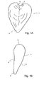
- Fig. 1 shows a breast cap 1 of slaughtered poultry.
- Fig. 1A is a rear view of the breast cap 1 and
- Fig. 1B is a side view.
- the breast cap 1 has a front 2, a neck side 3 and a back 4.
- the back 4 comprises the cutting plane along which the breast cap is cut loose from the remainder of the carcass of the slaughtered poultry.
- Fig. 1 clearly shows that the breast cap is substantially V-shaped.
- the top of the V shape is formed by the breast point 5 which is situated opposite the neck side 3.
- At least a part of the neck side 3 also has a V shape which is denoted in Fig. 1 by reference numeral 6.
- the neck side 3 of the breast cap 1 derives this V shape 6 from the wishbone.
- At least a part of the breastbone is present in the breast cap 1.
- Breast caps usually undergo further processing so that the breast meat which is present, for example in the form of fillets, is separated from the bones which are present in the breast cap, such as at least a part of the breastbone and in many cases also a part of the rib cage.
- the product carrier subsequently conveys the breast cap 1 along a track with one or more processing stations where the breast cap is processed.
- the processes can take place by hand, partly by hand or entirely automatically.
- Product carriers 50 which are suitable for breast caps 1 are often provided with a hook 51 (see Fig. 2 and Fig. 3 ).
- This hook 51 preferably acts on the breastbone in order to fix the breast cap relative to the product carrier.
- the product carrier 50 is further provided with a support surface 52 against which a breast cap 1 arranged on the product carrier 50 lies.
- the pin 57 ensures that the breast cap 1 sits securely in the hook 51.
- Fig. 3A shows the arrangement of a breast cap 1 on an alternative product carrier 50*
- Fig. 3B shows a breast cap 1 arranged on a product carrier 50* of this type.
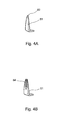
- the hook 51 can have various shapes, as shown in Fig. 4A and Fig. 4B .
- the shape with the single tip 53 is common, but it is also possible to provide the hook 51 with a V shape 54.
- This V shape 54 can receive a tendon connected to the breastbone, thus allowing the breast cap 1 to be positioned well on the product carrier 50.
- Fig. 5 shows an example of an embodiment of a system comprising a device 10 not according to the invention.
- the system from Fig. 5 comprises a feed plate 11, a plurality of set-up units 20 and a plurality of product carriers 50.
- the product carriers 50 are conveyed in the direction of transportation T by a drive 55 along a track 56.
- the set-up units 20 are in this embodiment conveyed along a track 40, driven by the drive 41.
- Fig. 6 shows an application unit in greater detail.
- Fig. 6A shows the application unit in the receiving position
- Fig. 6B shows the application unit in the transfer position.
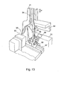
- Figures 11 , 12 and 13 also show an application unit.
- breast caps 1 are supplied by a supply device (not shown).
- the supply device can for example be a conveyor belt, a vibrating trough, a walking beam, a chute or a tray.
- An operator picks up a breast cap 1 from the supply device and lays it on the feed plate 11, with the back 4 directed upward and the neck side 3 turned away.
- the operator slides or lays the breast cap 1 in an application unit 20 via the feed plate 11.
- the actions performed by the operator are carried out by a robot or using other mechanical means.
- the application unit 20 comprises a holder 21, a neck support 22 and a pressing member 23.
- the holder 21 and the neck support 22 can each, independently of each other, pivot relative to the track 40 along which the set-up units 20 are movable.
- the pressing member 23 is slideable relative to the holder 21.
- the application unit comprises a holder tilting mechanism 24, a neck support tilting mechanism 25 and a pressing member movement mechanism 26 respectively.
- Each of these mechanisms is actuated by a cam track over which a cam roller 27, 28, 29 runs.
- the cam tracks are not shown in Fig. 5 .
- the components of the application unit 20 are mounted on a base part 36.
- the base parts 36 are in this example guided along a base part guide 37, so that the set-up units follow the track 40.
- the application member 23 has two pressing surfaces 38 which are set apart from each other and arranged to engage on either sides on the breast cap.
- the pressing surfaces 38 are arranged in such a way that they engage in proximity to the breast point.
- the pressing surfaces 38 are arranged substantially in an inverted V shape.
- the pressing member movement mechanism 26 is provided with a guide 39 for guiding the pressing member 23 along the holder 21.
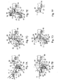
- Fig. 7 shows an example of an embodiment of the method not according to the invention, suitable to be carried out using the system according to Fig. 5 .
- Fig. 7A shows a first step in the method.
- An operator has picked up a breast cap 1 from the supply device and lays it on the feed plate 11.
- the breast cap 1 is laid on the feed plate 11 in such a way that the back 4 is directed upward, the front 2 rests on the feed plate 11, the neck side 3 is directed away from the operator and the breast point 5 is directed towards the operator.
- the pitch between successive set-up units 20 is substantially equal to the pitch between successive product carriers 50.
- the set-up units 20 and the product carriers 50 move at the same speed in the direction of transportation T. This movement can be continuous or stepwise.
- the application unit 20 is in the receiving position.
- Fig. 7B shows a second step in the method.
- the application unit is still in the receiving position.
- the operator lays the breast cap 1 in the holder 21 of the application unit 20.
- the back 4 of the breast cap 1 is directed upward, the front 2 rests on the holder 11, the neck side 3 is directed away from the operator and the breast point 5 towards the operator.
- the operator lays the breast cap in the holder 21 in such a way that the neck side 3 of the breast cap lies against the neck support 22.
- Laying the breast cap 1 in the holder 21 of the application unit requires no or little force to be exerted by the operator. This is in contrast to the known manual manner of arranging breast caps on product carriers.
- the neck support 22 is embodied in the form of an upright plate.
- the surface where the neck side 3 of the breast cap 1 lies against the neck support 22 is fairly narrow.
- the neck support 22 By causing the neck support 22 to engage at the point of the V shape 6 of the neck side 3 of the breast cap 1, the neck side 3 of the breast cap 1 is positioned (preferably centred) in the holder 21. Further centring is achieved if the holder 21 has a V-shaped cross section. This can thus centre the breast cap 1 over its entire length in the holder 21.
- Causing the neck side 3 of the breast cap 1 to lie against the neck support 22 also ensures correct positioning of the breastbone of the breast cap 1 relative to the holder 21, both in the longitudinal direction and in the transverse direction of the breast cap 1.
- the neck support can be configured as a flat plate which, in use, extends substantially transversely to the breast cap. A neck support of this type positions the breast cap in its longitudinal direction but not in its transverse direction relative to the holder.
- the pressing member 23 is not yet in contact with the breast cap 1. It is possible to provide the pressing member with a lock which locks the position of the pressing member in this phase of the process relative to the holder 21.
- Fig. 7C shows a third step in the method.
- the holder 21 is tilted about the pivot shaft 30 from the receiving position (indicated by broken lines) to the transfer position (indicated by solid lines). This movement is actuated via the cam track 31, cam roller 27 and holder tilting mechanism 24.
- the neck support 22 remains in the same position as during the first and the second step of the method. For the sake of clarity, the neck support tilting mechanism is not shown in Fig. 7C .
- the pressing member 23 is still locked relative to the holder 21 during this step of the method. It is however also possible for any locking to be cancelled between the situation of Fig. 7B and that of Fig. 7C or for no lock to be present, so that the pressing member 23 already slides downward somewhat along the holder during the tilting of the holder 21 from the receiving position to the transfer position and comes to lie against the breast cap 1.
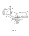
- the neck support 22 is shaped in such a way that the upper side of the neck support 22 lies at the same level as the top tip of the hook 51 of the product carrier 50 (see also Fig. 10 ).
- the breast cap at the top of the V shape 6 of the neck side 3, is guided by the neck support to a position relative to the product carrier 50 in which the breast cap 1 can be taken over by the product carrier 50.
- the breast cap enters a position in which the breast cap 1 can be transferred to the product carrier 50 in an effective manner. In the transfer position, the back 4 of the breast cap 1 lies against the support surface 52 of the product carrier 50.
- the neck support 22 has a shape which is adapted to the tilting movement of the holder 21. It will however be clear to the person skilled in the art that other shapes of the neck support are also possible.
- the neck support 22 is provided with a toothed surface. This offers the advantage that any tissue - such as skin, membranes or crop parts - present between the neck support 22 and the neck side 3 of the breast cap is pulled away during tilting of the holder 21, so that the neck side 3 comes to lie directly against the neck support 22.
- Fig. 7D shows a fourth step in the method.
- the neck support 22 is tilted away about the pivot shaft 33 by the neck support tilting mechanism 25.
- This mechanism 25 is actuated by the cam track 32 and cam roller 28.
- the breast cap 1 is now carried loosely by the hook 51 of the product carrier 50.
- the pin 57 is still retracted in the product carrier 50.
- Fig. 7E shows the fifth step in the method.
- the pressing member 23 is actively pressed downward.
- the pressing member 23 presses the breast cap securely onto the product carrier 50.
- the hook 51 preferably enters into engagement with a part of the breastbone or with the tissue in the immediate vicinity of the breastbone.
- the breast cap After the breast cap 1 has been pressed onto the product carrier 50, the breast cap sits securely on the product carrier 50 and the application unit can release the breast cap 1. For this purpose, the pressing member is raised again so that it is no longer engaging the breast cap 1.
- Pressing the pressing member down and raising it again can be carried out by a cam track having a profile suitable for this purpose. It is however also possible to cause the cam roller 29 to run in a track 34, and to move this track down and subsequently back up using an actuator.
- a pneumatic cylinder is for example suitable to serve as the actuator.
- Fig. 7F shows the final result of the method according to the invention: a breast cap 1 arranged on a product carrier 50.
- Fig. 8 is a further detailed view of the arrangement of the breast cap 1 on the product carrier 50. For the sake of clarity, Fig. 8 shows just a few components of the application unit 20.
- Fig. 8A shows that the neck support 22 brings the breast cap 1 to the product carrier 50.
- the broken line 7 indicates the top of the V shape 6 of the neck side 3.
- the neck support 22 acts on this top 7 and takes it above the top of the hook 51.
- Fig. 8B shows that the neck support 22 of the breast cap 1 is tilted away about the pivot shaft 33.
- the breast cap 1 continues to lie against the product carrier 50.
- the breast cap 1 is in this case held in position by the holder 21 (not shown in Fig. 8B ).
- Fig. 8C shows that the pressing member 23 presses the breast cap 1 downward relative to the product carrier 50. As a result, the breast cap 1 is pressed securely onto the hook 51. This is an action which requires a relatively high degree of force and caused injuries to operators in the case of the known method.
- Fig. 8D shows a breast cap 1 arranged on the product carrier 50.
- the pin 57 of the product carrier is extended in the direction of the breast cap 1. As a result, the breast cap is fixed even more securely on the product carrier 50.
- Fig. 9 shows the cam track 31 for actuating the tilting of the holder 21, the cam track 32 for actuating the tilting of the neck support 22 and the track 34 for activating the movement of the pressing member 23.
- the track 34 interacts with the pneumatic cylinder 35 which moves the track 34 downward and upward in the direction indicated by arrow P.
- Arrow T indicates the direction of transportation of the product carriers 50.
- Fig. 14 shows a second an embodiment of the device and method not according to the invention.
- separating line carriers 150 are used as product carriers.
- Whole carcasses 101 (which are preferably already made ready to cook and have optionally already been cooled) are arranged on these separating line carriers 150.
- the application unit 120 comprises a holder 121 which is adapted for receiving a whole carcass 101.
- the holder 121 is shaped in such a way that the carcass 101 is positioned in the holder 121 in an unambiguous manner.
- the holder 121 is provided with oblique sides 123 which ensure that the carcass 101 is longitudinally centred in the holder 121.
- the holder 121 is also provided with recesses 122 in which the wings 102 (or the parts of the wings 102 that are present) can be received. These recesses 122 thus help to position the carcass 101 relative to the holder 121.
- the holder 121 is mounted on a base part 136 which is movable along a base part guide 137.
- the holder 121 is pivotable relative to the base part 136 about the pivot shaft 130.
- Fig. 14 includes a feed plate 111 which is placed in such a way that an operator 112 or a robot can easily lay a carcass 101 in the holder 121 of an application unit 120 from the feed plate 111 when the holder 121 is in the receiving position.
- Fig. 14 shows various steps in the use of the second exemplary embodiment of the device according to the invention.
- Fig. 14A shows the first step in which a carcass 101 is laid on the feed plate 111, with the back on the plate and the breast facing upward.
- the neck side of the carcass part 101 points towards the application unit 120 and the legs point away from the application unit 120.
- the holder 121 of the application unit 120 is in the receiving position.
- the positions of the feed plate 111 and the holder 121 are adapted to each other in such a way that an operator 112 can easily slide the carcass 101 from the feed plate 111 into the holder (see arrow P1).
- An overhead transportation track comprising a plurality of product carriers in the form of separating line carriers 150 is provided.
- the application unit 120 can to move along a base part guide 137.
- a drive is provided for this purpose (not shown), for example in the same way as shown in combination with the first exemplary embodiment.
- the overhead transportation track comprising the separating line carriers 150 will move continuously at a substantially fixed speed.
- the separating line carriers can be moved intermittently.
- the carcass 101 can be transferred from the application unit 120 to the separating line carrier 150 while the separating line carriers 150 are stationary.
- Fig. 14 shows just a single application unit 120.
- an advantageous variant provides a plurality of set-up units which are preferably placed at a fixed mutual distance, which mutual distance corresponds to the mutual distance of the product carriers in which or on which the carcass 101 is arranged.
- Fig. 14B shows a following step.
- the carcass 101 to be suspended from the separating line carrier is now arranged in the holder 121 of the application unit.
- the wings 102 lie in the recesses 122 in the holder 121.
- the position of the carcass 101 relative to the longitudinal direction of the holder 121 is thus defined.
- the upright sides 123 of the holder 121 centre the carcass 101 in the holder 120.
- the separating line carrier 150 contains a lock 151 which has an open and a closed position. In the open position, it is possible to arrange a carcass 101 (or a carcass part such as a leg) in the separating line carrier 150 or to remove it from the separating line carrier 150. In the closed position, a carcass (or carcass part) which is present sits in the separating line carrier 150 in a locking manner.
- the lock is operated by an operating member which is arranged next to the overhead transportation track.
- the holder tilting mechanism 124 swivels the holder 121 from the receiving position ( Fig. 14B ) about the pivot shaft 130 to the transfer position ( Fig. 14C ), for example in the direction indicated by arrow P2 (see Fig. 14C ).
- the wings 102 of the carcass 101 come to lie against the edge of the recesses 122 under the force of gravity. This positions the carcass 101 relative to the holder 121.
- a number of components of the device according to the invention are omitted in Fig. 14C .
- the legs of the carcass 101 are brought into the leg slots 153 in the separating line carrier 150, for example by means of a guide (not shown) for the legs.
- the lock 151 is closed. This takes place by moving the lever 154 upward, for example in the direction indicated by arrow P5.
- the upward movement of the lever 154 can for example be achieved by a cam track which is arranged along the suspended transportation track and guides the lever.
- the carcass 101 is securely suspended from the separating line carrier 150.
- the holder 121 can now be swivelled back from the transfer position ( Fig. 14C ) to the receiving position (see Fig. 14D ), for example in the direction indicated by arrow P3.
- the application unit is then ready again to receive a following carcass 101. If necessary or desired, the application unit is for this purpose first brought back to a suitable position relative to the feed plate 111.
- Fig. 15 shows a variant of the device and method according to Fig. 14 .
- the carcass 101 is suspended not from a separating line carrier 150 but from a cooling line carrier 155.
- corresponding components are denoted by corresponding reference numerals.
- the variant of Fig. 15 and the variant of Fig. 14 work in corresponding ways.
- the variant of Fig. 15 is particularly suitable for use in the case of whole carcasses 101 which are made ready to cook.
- the legs are first arranged, as shown in Fig. 15C , in the wide parts of the leg slots 154 in the cooling line carrier 155.
- the carcass 101 falls downwards under the force of gravity in the direction indicated by arrows P4, as a result of which the legs enter the narrow part of the leg slots 154.
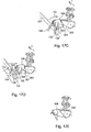
- Fig. 16 shows a first embodiment of the device and method according to the invention.
- This third embodiment corresponds to a high degree to the embodiment of Fig. 14 , insofar as in the embodiment according to Fig. 16 the application unit 120 has a holder 221 which is suitable for receiving a back half 105.
- corresponding components are denoted by corresponding reference numerals.
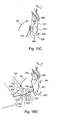
- Fig. 16A and Fig. 16B show the same steps for a back half 105 as Fig. 14A and Fig. 14B show for a whole carcass 101.
- Fig. 16C shows the transfer of the back half 105 from the application unit 120 comprising the holder 221 to the separating line carrier 150.
- the back half 105 cannot be released from the holder 221 by the tilting-away of the holder 221, such as is the case in Fig. 14C and Fig. 14D in the holder 121.
- the separating line carrier 150 is moved upward (arrow P6 in Fig. 16C ) relative to the holder 221, for example by causing the path of the overhead transportation track, from which the separating line carriers 150 are suspended, to run upward relative to the device according to the invention. This draws the back half 105 out of the holder 221.
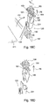
- Fig. 17 shows a further embodiment of the device and method not according to the invention. Again, corresponding components are denoted by corresponding reference numerals. The functioning of this embodiment is broadly the same as that of the embodiments described hereinbefore.
- a front half 106 is arranged on a product carrier in the form of a carrying block 350.
- the carrying block 350 engages on the inside of the front half 106.
- the carrying block 350 is preferably connected to an overhead transportation track.
- the holder 321 is suitable for receiving a front half 106.
- the front half 106 is in this example arranged in the holder 321 with its neck side directed away from the carrying block 350 (arrow P1 in Fig. 17A ).
- the holder 321 is shaped in such a way that the front half 106 is well positioned in the holder and thus relative to the carrying block 350.
- Fig. 17A shows the front half 106 in the holder 321.
- Fig. 17B the holder is still in the receiving position.
- Fig. 17C shows that the holder 321 is tilted with the front half 106 therein.
- the holder 321 is for this purpose tilted about the pivot shaft 130.
- the tilting movement is imposed on the holder by the holder tilting mechanism 124, a part of which is shown in Fig. 17C .
- the front half 106 is substantially aligned with the carrying block 350.
- the front half 106 can be slid onto the carrying block. This is carried out by the pressing member 323 (see Fig. 17D ).
- the pressing member 323 is arranged below the feed plate 111.
- the pressing member 323 presses the holder 321 in the direction of the carrying block 350.
- the base part 136 comprises a guide block 340 which guides the holder in the direction of the carrying block 350 during this movement.
- the front half 106 is thus arranged on the carrying block 350.
- the holder 321 returns to its initial position, such as is shown in Fig. 17A .
- This can for example take place under the influence of gravity or with the aid of for example pneumatic cylinders or a cam track/cam roller structure.
- Fig. 17E shows a front half 106 arranged on the carrying block 350.
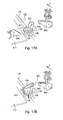
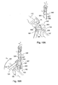
- Fig. 18 shows a second embodiment of the device and method according to the invention.
- the holder 421 is suitable for receiving two legs 107 or parts of legs.
- the holder 421 comprises four side plates 422 which, in pairs, can secure and can position a leg 107.
- the legs are arranged in a separating line carrier 150. It is however also possible to use a different type of product carrier, for example a cooling line carrier.
- Fig. 18 two legs are arranged in the product carrier at the same time.
- a person skilled in the art will understand that the embodiment according to Fig. 18 can easily be adapted for a different number of legs.
- Fig. 18A shows that an operator 112 places the legs 107 in the holder 421.
- Formed in the variant of Fig. 18 are recesses 423, the shape of which corresponds substantially to the shape of a leg 107. This helps to position the leg 107 relative to the holder 421. It is however also conceivable for such a recess 423 not to be provided. This results in a holder 421 which can be produced more inexpensively.
- the side plates 422 can be fixedly connected to the remainder of the holder 421, although a variant in which the side plates 422 can pivot relative to the remainder of the holder 421 is also conceivable.
- the pivot shaft of the side plates 422 then preferably runs substantially parallel to the longitudinal direction of a leg received in the holder.
- a torsion spring for example, then exerts a spring force on the side plates 422, pressing the side plates towards the remainder of the holder 421.
- the natural variation in leg thicknesses which occur can be effectively accommodated.
- Fig. 18B shows the tilting of the holder 422 from the application position to the transfer position.
- the holder 421 pivots about the pivot shaft 130.
- Fig. 18C the holder 421 has entered the transfer position.
- the tips of the legs 107 have arrived in the leg slots 153 in the separating line carrier 150, for example by means of a guide (not shown) for the legs.
- the lock 151 of the separating line carrier 150 is closed by raising the lever 154 in the direction indicated by arrow P5. This raising is for example achieved by guiding the separating line carrier 150 along a cam track (not shown).
- the person skilled in the art is familiar with this principle.
- the legs 107 can be released from the holder in various ways. It is possible to move the separating line carrier 150 upward in the direction of arrow P6 in Fig. 18D relative to the holder 421, for example by causing the path of the overhead transportation track, from which the separating line carriers are 150 suspended, to run upward relative to the device according to the invention. If, however, the holder is configured with pivotable side plates 422, the legs 107 are simply released from the holder 421 by tilting the holder 421 back to the receiving position.
- Fig. 19 shows a third embodiment of the device and method according to the invention.
- carcass parts in this example legs 107 or parts thereof, are arranged in a marinating hook 550.
- this embodiment is also suitable for the arrangement of other carcass parts, for example wings or parts of wings, on hooks of this type.
- Fig. 19A shows how a leg 107 is arranged in the holder 521 by an operator 112. Just as in all other embodiments shown, this could also be done by, for example, a robot or another mechanical supply system rather than by a human operator.
- the holder 521 is designed for receiving one leg 107.
- Variants wherein a plurality of legs, leg parts, wings, wing parts or other carcass parts can be placed and/or positioned in the holder are conceivable.
- the holder 521 is provided with a curved plate 522 for securing the leg 107 in the holder 521. Also formed in the holder 521 is a recess, the shape of which corresponds substantially to the shape of a leg 107. This recess 523 helps to position the leg 107 in the holder 521.
- the curved plate 522 can be configured as one component, although it is possible for there to be two side plates as shown in Fig. 18 . It is in this case possible, just as in the variant of Fig. 18 , for these side plates to be fixedly connected to the remainder of the holder or for them to be pivotable as described in the discussion of Fig. 18 .
- Fig. 19A shows that the marinating hook has two legs 551. These legs are moveable, usually pivotable, relative to each other.
- Fig. 19A shows the marinating hook 550 in the open position, the legs 551 being at a distance from each other such that a carcass part to be carried, in this example a poultry leg 107, can be arranged between the legs 551.
- a spreader 560 is arranged between the legs 551 which spreads legs of the marinating hook 550 preferably counter to a spring force or other restoring force.
- Fig. 19B shows that the holder 521 is transferred from the receiving position ( Fig. 19A ) to the transfer position. In this embodiment too, this results from the tilting of the holder 521 about the pivot shaft 130 in the direction indicated by arrow P2.
- the free tip of the poultry leg 107 comes to lie between the legs 551 of the marinating hook 550.
- Fig. 19C shows that the marinating hook is closed. This results from the withdrawing of the spreader 560, for example in the direction indicated by arrow P8. A spring force or other restoring force ensures that the legs 551 move towards each other (arrow P7) and securely clamp the poultry leg 107.
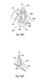
- Fig. 20 shows a fourth embodiment of the device and method according to the invention.
- a carcass part for example a leg 107 or a part thereof or a wing or a part thereof, is fastened to the product carrier 650.
- the product carrier 650 is provided with a skewer 651 which is designed to pierce at least partly through the carcass part and thus to carry the carcass part.
- the product carrier 650 is placed on the guide rail 652 and can move relative to this rail in the direction of transportation T.
- just one product carrier 650 is shown on the rail 652, there are preferably a plurality of product carriers 650 which are at a fixed mutual distance.
- the product carriers 650 are moved by a drive comprising, for example, a chain 653.
- Fig. 20A shows the introduction of a carcass part, in this example a leg 107, in the holder 621 of the application unit 120.
- a human operator places the leg 107 in the holder, although this could also be carried out by a robot or another mechanical device.
- the holder 621 is in the receiving position.
- the holder 621 is provided with a recess 623, the shape of which corresponds substantially to the shape of the leg 107. This recess helps to position the leg 107 relative to the holder 621.
- Fig. 20B shows the transfer of the holder with the leg 621 from the receiving position to the transfer position (arrow P2).
- the holder 621 in this case pivots about the pivot shaft 130.
- the speed of the movement of the holder 621 from the receiving position to the transfer position is preferably so high that the mass inertia holds the leg 107 in the holder 621. It is also possible to make the recess 623 so deep that the leg 107 remains therein during the pivoting to the transfer position.
- the product carrier moves towards the holder, the holder remaining substantially in the receiving position.
- Fig. 20C shows the arrangement of the leg 107 on the product carrier 650.
- the holder 621 presses the leg 107 onto the skewer 651 of the product carrier 650.
- the leg 107 is positioned in such a way that the skewer 651 passes between the bones of the leg 107, so that no bone splinters are caused in the meat.
- the skewer 651 it is possible for the skewer 651 to have one or more barbs which ensure that the leg 107 remains suspended from the skewer 651 when the holder is tilted back from the transfer position to the receiving position.
- Fig. 20D shows a leg 107 arranged on the product carrier 650.
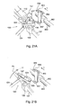
- Fig. 21 shows an fifth embodiment of the device and method according to the invention.
- Fig. 21A shows the introduction of a carcass part, in this example a leg 107, into the holder 921 of the application unit 120 (arrow P1).
- a human operator 112 places the leg 107 in the holder, although this could also be carried out by a robot or another mechanical device.
- the holder 921 is in the receiving position.
- Fig. 21B shows the transfer of the holder 921 with the leg 107 from the receiving position to the transfer position (arrow P2).
- the holder 921 in this case pivots about the pivot shaft 130.
- the product carrier 950 is provided with a receiving slot 956 and with a recess 957.
- the recess 957 is intended to receive a bone part 107* projecting from the wide side of the leg 107.
- the recess 957 can, if desired, also receive a different projecting part of a carcass part.
- Fig. 21C shows the holder 921 in the transfer position.
- the narrow part of the leg 107 is arranged in the receiving slot 956, whereas the projecting bone part 107* lies in the recess 957.
- the holder 921 has returned to the receiving position.
- the leg 107 is arranged in the product carrier 950, but is still slightly loose.
- guides 960 and 961 and the product carrier are provided with a cam roller 955.
- the leg guide 960 is located above the leg.
- the roller guide 961 is located below the roller 955.
- the roller guide 961 presses the roller 955, and thus the product carrier 950, upward.
- the leg guide 960 prevents the leg 107 arranged in the product carrier 950 from moving upwards too far with the product carrier.
- the projecting bone part 107* is pressed deeper into or even through the recess 957. This is shown in Fig. 21E .
- Fig. 22 shows a second example of an embodiment of a system comprising devices not according to the invention.
- the system of Fig. 22 comprises a number of set-up units 720 according to the invention.
- Each of the set-up units 720 comprises a holder 721 and a base part 736.
- the holder 721 is pivotable relative to the base part 736.
- the set-up units are moved by means of a drive (not shown) along a base part guide 737 in the direction of arrow T.
- the system of Fig. 22 comprises a supply station 710 with a feed plate 711.
- An operator places a carcass 701 on the feed plate 711 and slides the carcass over the feed plate 711 into the holder of a passing set-up unit 720. As it passes the supply station 710, the holder 721 is in the receiving position.
- the set-up units 720 are not directly coupled to one another. As a result, there does not have to be a fixed distance between successive set-up units.
- the distance between successive set-up units can also vary in accordance with the position of the set-up units in the system.
- the set-up units are brought to the application location 770 by their drive.
- the carcasses are arranged on the product carriers 750.
- the holders 721 of the set-up units are tilted to the transfer position in the supply station.
- the speed of the set-up units and the mutual distances thereof in the application location are adapted to the speed of the product carriers 750 and the mutual distances thereof.
- the speed of the set-up units at the application location will be higher than in the supply station.
- the mutual distance between successive set-up units will usually be greater in the application location than in the supply station.
- the variation in speed and mutual distances is for example achieved by a drive having one or more servomotors or having a mechanism comprising eccentric gear-wheels.
- the set-up units are returned to the supply station.
- the holders 721 are in this case tilted back to the receiving position so that when they arrive at the supply station, they can again receive a following carcass.
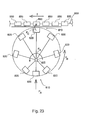
- Fig. 23 is a schematic view of an alternative embodiment of the system according to the invention.
- the system comprises a plurality of set-up units 820 which are connected to a central shaft 825.
- the set-up units can be connected to a disc which rotates about the central shaft 825 in the direction indicated by arrow P R . The distance between an individual set-up unit and the central shaft 825 varies during a revolution about the central shaft 825.
- carcasses or carcass parts which are supplied in the direction indicated by arrow PA are arranged on or in passing set-up units 820.
- the set-up units After the arrangement of a carcass part, the set-up units continue to rotate in the direction indicated by arrow PB.
- the distance from the set-up unit 820 to the central shaft 825 becomes greater and greater, as a result of which the mutual distance between successive set-up units 820 and the speed of the set-up units 820 increases.
- the increase in distance and speed is such that when a set-up unit arrives at the application location 870, the speed and the distance are adapted to the product carriers of the product line 855 which move in the direction of arrow T.
- the carcasses or carcass parts are arranged in or on the product carriers 850 in the direction indicated by arrow P C .
- the empty set-up units afterwards return to the supply station 810 where they are again provided with a carcass part.
- the distance between the set-up unit and the central shaft is again reduced, so that the speed and the mutual distance between successive product carriers is again suitable for placing carcasses or carcass parts in the set-up units.
- Fig. 23 shows a constructionally simple manner to create a variation in distance and speed of the product carriers.
- the carcass part can be placed in a holder of a set-up unit at a relatively low speed; this is desirable from the point of view of ergonomics.
- This system ensures that after the operator has arranged the carcass part, the carcasses or carcass parts are accelerated so that they can be arranged in a high-speed production line. In this way, it is possible to arrange products in a high-speed production line in an ergonomically expedient manner.
Landscapes
- Life Sciences & Earth Sciences (AREA)
- Engineering & Computer Science (AREA)
- Wood Science & Technology (AREA)
- Zoology (AREA)
- Food Science & Technology (AREA)
- Processing Of Meat And Fish (AREA)
Abstract
Description
- The invention relates to arranging a carcass part of slaughtered poultry on or in a product carrier.
- For use in poultry slaughterhouses, transportation devices are known with a product carrier or usually a plurality of product carriers which are each suitable for arranging thereon or therein a carcass part of slaughtered poultry, so that the carcass part can be moved with the aid of the transportation device. Usually the direction of transportation forms a transportation path along which one or more processing stations are located, so that one or more processes can be carried out on the carcass part. These processes can be performed automatically by a suitable processing device but can also, or in combination, be carried out by hand. Carcass parts of slaughtered poultry that are processed in this way include, for example, breast caps, front halves, back halves, legs, quarters and drumsticks.
- As is known, poultry slaughter installations are largely mechanized, so that a high processing rate and a high yield and quality can be achieved. However, to date, the placing of a carcass part of slaughtered poultry on or to a product carrier often still takes place by hand in a set-up station wherein one person or usually two persons continuously place carcasses or carcass parts on passing product carriers.
-
NL8201782 - Arranging carcasses or carcass parts of slaughtered poultry manually on or in product carriers is unpleasant and hard work which can lead to physical complaints.
- A further drawback of the known devices is that the carcasses or carcass parts do not, once arranged on the product carrier, all assume the same position relative to the product carrier on which they are arranged. This adversely influences the reproducibility of the process to be carried out on the carcasses or carcass parts. In practice, this leads to a lower meat yield than could theoretically be possible.
- An object of the invention is to provide a device for arranging a carcass part of slaughtered poultry on or in a product carrier.
- This object is achieved by a device according to
claim 1. In this device, the holder, together with the associated positioning means, effects a movement of the carcass part to a transfer position, wherein the carcass part is positioned in an effective manner. In the transfer position, the carcass part can be arranged on or in a product carrier. - An advantage of the device according to the invention is that the carcasses or carcass parts are arranged on or in a product carrier in a reproducible manner. As a result, the carcasses or carcass parts all have (substantially) the same position relative to the product carrier on which or in which they are arranged and the processes can be carried out on the carcasses or carcass parts in a precise manner. This benefits the meat yield.
- In an advantageous embodiment, the device according to the invention is provided with an application mechanism for arranging the carcass part on or in the product carrier. It is also envisaged that an application mechanism could be present which is not part of the device but which is, for example, arranged next to the track of the product carriers.
- The positioning means for the carcass part can form part of the holder but can also be separate from the holder. It is also conceivable for the positioning means to partly form part of the holder and to be partly separate therefrom, as will become apparent from the exemplary embodiment described in greater detail.
- Arranging the product carrier of a carcass part which is already pre-positioned in the holder can then efficiently be carried out by the application mechanism.
- It is known to arrange a carcass part on a product carrier which is designed to arrange the carcass part thereon by pressing the carcass part onto the product carrier. In the case of the device according to the invention, any application mechanism is then preferably configured as a pressing mechanism which is designed to press - in the transfer position of the holder with the carcass part - the carcass part onto the product carrier, so that the carcass part is arranged on the product carrier. The Applicant has, for example, introduced to the market transportation devices which are shown in this application by way of example and comprise a plurality of product carriers. A specific embodiment shown herein provides for a breast cap to be pressed from above onto the product carrier with the breast point upward and the neck side at the bottom.
- A suitable embodiment provides for the possibility of laying a carcass part in a holder without any significant force having to be exerted on the carcass part. That laying-in can then for example take place by hand. The device according to the invention subsequently places the carcass part on the product carrier and supplies in this case the force which is necessary to, for example, press the carcass part securely onto the product carrier. This makes the task of arranging carcasses or carcass parts on product carriers physically less demanding.
- A further advantage of the device according to the invention is that a higher set-up speed can be achieved as a result of the fact that the carcasses or carcass parts can be laid in the movable holder significantly more quickly than forcefully arranging carcasses or carcass parts on or in a product carrier, such as is often the case in the known devices. This is particularly important because in modern poultry slaughterhouses and modern poultry-processing plants there is a tendency towards increasingly high production speeds. This leads to increasingly high production line speeds, as a result of which the speed at which products are arranged in the line must also increase. The device according to the invention can help to make this easier.
- In an advantageous embodiment a feed plate is provided on which a carcass part can be laid and then can be slid away from the feed plate so that the carcass part enters the movable holder - which is in the receiving position.
- The device according to the invention can for example be used to arrange back halves, legs or drumsticks in separating line carriers or cooling line carriers. It is also possible to arrange for example legs, drumsticks, thigh pieces or wings with the aid of the device according to the invention in a product carrier which passes these carcass parts through a system for coating and/or marinating. Also known are product carriers comprising a skewer for carrying the carcass part. A skewer of this type is pierced at least partly through the carcass part to be carried, preferably between any bones or bone parts present in the carcass part.
- The invention also provides a system for bringing into position and arranging carcass part of slaughtered poultry on or in a product carrier, the system comprising at least one device according to the invention. Preferably, in a system of this type, at least the holder of the device is moveable along a track by associated drive means, in such a way that in a supply station along the track a carcass part can be received in the holder and is in the transfer position at an application location downstream of the supply station the holder. At the application location - with the holder with the carcass part in the transfer position - the carcass part can then be arranged on the product carrier.
- Preferably, a system of this type comprises a plurality of devices according to the invention. These devices can have fixed or variable mutual distances.
- It is envisaged that the devices can move along the track independently of one another.
- In an advantageous embodiment of the system according to the invention, the devices pass the supply station at a low speed and preferably a relatively small mutual distance. As a result, there is a relatively large amount of time to arrange a carcass part in the holder of one of the devices of the system. Once a carcass part has been arranged in the holder and once the device has passed the supply station, the speed of the device can then be increased. The mutual distance between successive devices will then also increase in most cases. In this case, the mutual distances between successive devices and the speed of the devices along the track are preferably at least substantially equated to the mutual distance and the speed of the product carriers at the site of the application location.
- The invention will be described hereinafter based on the drawings showing an exemplary embodiment in a non-limiting manner.
- In the drawings:
-
Fig. 1 shows a breast cap of slaughtered poultry; -
Fig. 2 shows a breast cap placed on a product carrier; -
Fig. 3 shows a combination of a breast cap with an alternative product carrier; -
Fig. 4 shows two variants of a hook of a product carrier; -
Fig. 5 shows a first example of an embodiment of a system comprising a device not according to the invention; -
Fig. 6 shows an application unit of the device according toFig. 5 ; -
Fig. 7 shows an example of an embodiment of the method not according to the invention, suitable to be carried out using the system according toFig. 5 ; -
Fig. 8 shows (in detail) the arrangement of a breast cap on the product carrier; -
Fig. 9 shows the cam tracks for actuating the application unit; -
Fig. 10 shows the position of the neck support relative to a hook of a product carrier prior to the transfer of the breast cap from the holder to the product carrier in the first embodiment of a device not according to the invention; -
Fig. 11 shows an application unit of the first embodiment not according to the invention in the receiving position; -
Fig. 12 shows the application unit fromFig. 11 in the transfer position; -
Fig. 13 shows the application unit fromFig. 11 in a position in which a breast cap can be pressed onto the product carrier; -
Fig. 14 shows a second embodiment of the device and method not according to the invention; -
Fig. 15 shows a variant of the embodiment of the device and method according toFig. 14 ; -
Fig. 16 shows a first embodiment of the device and method according to the invention; -
Fig. 17 shows a further embodiment of the device and method not according to the invention; -
Fig. 18 shows a second embodiment of the device and method according to the invention; -
Fig. 19 shows a third embodiment of the device and method according to the invention; -
Fig. 20 shows a fourth embodiment of the device and method according to the invention; -
Fig. 21 shows a fifth embodiment of the device and method according to the invention; -
Fig. 22 shows a second example of an embodiment of a system comprising a device not according to the invention; and -
Fig. 23 is a schematic view of an alternative embodiment of the system according to the invention. -
Fig. 1 shows abreast cap 1 of slaughtered poultry.Fig. 1A is a rear view of thebreast cap 1 andFig. 1B is a side view. Thebreast cap 1 has afront 2, aneck side 3 and aback 4. Theback 4 comprises the cutting plane along which the breast cap is cut loose from the remainder of the carcass of the slaughtered poultry. -
Fig. 1 clearly shows that the breast cap is substantially V-shaped. The top of the V shape is formed by thebreast point 5 which is situated opposite theneck side 3. - At least a part of the
neck side 3 also has a V shape which is denoted inFig. 1 byreference numeral 6. Theneck side 3 of thebreast cap 1 derives thisV shape 6 from the wishbone. - Although not shown in
Fig. 1 , at least a part of the breastbone is present in thebreast cap 1. - Breast caps usually undergo further processing so that the breast meat which is present, for example in the form of fillets, is separated from the bones which are present in the breast cap, such as at least a part of the breastbone and in many cases also a part of the rib cage.
- This is generally done by placing the
breast cap 1 on aproduct carrier 50 in a set-up station. The product carrier subsequently conveys thebreast cap 1 along a track with one or more processing stations where the breast cap is processed. The processes can take place by hand, partly by hand or entirely automatically. -
Product carriers 50 which are suitable forbreast caps 1 are often provided with a hook 51 (seeFig. 2 andFig. 3 ). Thishook 51 preferably acts on the breastbone in order to fix the breast cap relative to the product carrier. Theproduct carrier 50 is further provided with asupport surface 52 against which abreast cap 1 arranged on theproduct carrier 50 lies. Thepin 57 ensures that thebreast cap 1 sits securely in thehook 51. - The person skilled in the art is familiar with various sorts of
product carriers 50 which are suitable for carrying a breast cap. Product carriers of this type are known for example fromEP 0254332 and fromNL 1014845 Fig. 3A shows the arrangement of abreast cap 1 on analternative product carrier 50*, andFig. 3B shows abreast cap 1 arranged on aproduct carrier 50* of this type. - The
hook 51 can have various shapes, as shown inFig. 4A and Fig. 4B . The shape with thesingle tip 53 is common, but it is also possible to provide thehook 51 with aV shape 54. ThisV shape 54 can receive a tendon connected to the breastbone, thus allowing thebreast cap 1 to be positioned well on theproduct carrier 50. -
Fig. 5 shows an example of an embodiment of a system comprising adevice 10 not according to the invention. - The system from
Fig. 5 comprises afeed plate 11, a plurality of set-upunits 20 and a plurality ofproduct carriers 50. Theproduct carriers 50 are conveyed in the direction of transportation T by adrive 55 along atrack 56. The set-upunits 20 are in this embodiment conveyed along a track 40, driven by thedrive 41. -
Fig. 6 shows an application unit in greater detail. In this case,Fig. 6A shows the application unit in the receiving position andFig. 6B shows the application unit in the transfer position.Figures 11 ,12 and13 also show an application unit. - In the system according to
Fig. 5 , breast caps 1 are supplied by a supply device (not shown). The supply device can for example be a conveyor belt, a vibrating trough, a walking beam, a chute or a tray. An operator picks up abreast cap 1 from the supply device and lays it on thefeed plate 11, with theback 4 directed upward and theneck side 3 turned away. - The operator slides or lays the
breast cap 1 in anapplication unit 20 via thefeed plate 11. In an alternative embodiment of the system according toFig. 5 , the actions performed by the operator are carried out by a robot or using other mechanical means. - The
application unit 20 comprises aholder 21, aneck support 22 and a pressingmember 23. In the embodiment shown, theholder 21 and theneck support 22 can each, independently of each other, pivot relative to the track 40 along which the set-upunits 20 are movable. The pressingmember 23 is slideable relative to theholder 21. In order to carry out these movements, the application unit comprises aholder tilting mechanism 24, a necksupport tilting mechanism 25 and a pressingmember movement mechanism 26 respectively. Each of these mechanisms is actuated by a cam track over which acam roller Fig. 5 . The components of theapplication unit 20 are mounted on abase part 36. Thebase parts 36 are in this example guided along abase part guide 37, so that the set-up units follow the track 40. - In the application unit shown in
Figures 11 ,12 and13 , theapplication member 23 has twopressing surfaces 38 which are set apart from each other and arranged to engage on either sides on the breast cap. In this example, thepressing surfaces 38 are arranged in such a way that they engage in proximity to the breast point. The pressing surfaces 38 are arranged substantially in an inverted V shape. - In the example from
Figures 11 ,12 and13 , the pressingmember movement mechanism 26 is provided with aguide 39 for guiding the pressingmember 23 along theholder 21. -
Fig. 7 shows an example of an embodiment of the method not according to the invention, suitable to be carried out using the system according toFig. 5 . -
Fig. 7A shows a first step in the method. An operator has picked up abreast cap 1 from the supply device and lays it on thefeed plate 11. Thebreast cap 1 is laid on thefeed plate 11 in such a way that theback 4 is directed upward, thefront 2 rests on thefeed plate 11, theneck side 3 is directed away from the operator and thebreast point 5 is directed towards the operator. - As can also be seen in
Fig. 5 , the pitch between successive set-upunits 20 is substantially equal to the pitch betweensuccessive product carriers 50. Preferably, the set-upunits 20 and theproduct carriers 50 move at the same speed in the direction of transportation T. This movement can be continuous or stepwise. - In the step of
Fig. 7A , theapplication unit 20 is in the receiving position. -
Fig. 7B shows a second step in the method. Also now, the application unit is still in the receiving position. In this step of the method, the operator lays thebreast cap 1 in theholder 21 of theapplication unit 20. In this case too, theback 4 of thebreast cap 1 is directed upward, thefront 2 rests on theholder 11, theneck side 3 is directed away from the operator and thebreast point 5 towards the operator. Preferably, the operator lays the breast cap in theholder 21 in such a way that theneck side 3 of the breast cap lies against theneck support 22. Laying thebreast cap 1 in theholder 21 of the application unit requires no or little force to be exerted by the operator. This is in contrast to the known manual manner of arranging breast caps on product carriers. - In this example, the
neck support 22 is embodied in the form of an upright plate. As a result, the surface where theneck side 3 of thebreast cap 1 lies against theneck support 22 is fairly narrow. By causing theneck support 22 to engage at the point of theV shape 6 of theneck side 3 of thebreast cap 1, theneck side 3 of thebreast cap 1 is positioned (preferably centred) in theholder 21. Further centring is achieved if theholder 21 has a V-shaped cross section. This can thus centre thebreast cap 1 over its entire length in theholder 21. Causing theneck side 3 of thebreast cap 1 to lie against theneck support 22 also ensures correct positioning of the breastbone of thebreast cap 1 relative to theholder 21, both in the longitudinal direction and in the transverse direction of thebreast cap 1. In an alternative embodiment (not shown), the neck support can be configured as a flat plate which, in use, extends substantially transversely to the breast cap. A neck support of this type positions the breast cap in its longitudinal direction but not in its transverse direction relative to the holder. - It will be clear to the person skilled in the art that desired positioning of the
breast cap 1 in theholder 21 can also be obtained in other manners, for example by way of a V-shaped neck support. - In the step of
Fig. 7B , the pressingmember 23 is not yet in contact with thebreast cap 1. It is possible to provide the pressing member with a lock which locks the position of the pressing member in this phase of the process relative to theholder 21. -
Fig. 7C shows a third step in the method. In this third step, theholder 21 is tilted about thepivot shaft 30 from the receiving position (indicated by broken lines) to the transfer position (indicated by solid lines). This movement is actuated via thecam track 31,cam roller 27 andholder tilting mechanism 24. Theneck support 22 remains in the same position as during the first and the second step of the method. For the sake of clarity, the neck support tilting mechanism is not shown inFig. 7C . - In the example of
Fig. 7C , the pressingmember 23 is still locked relative to theholder 21 during this step of the method. It is however also possible for any locking to be cancelled between the situation ofFig. 7B and that ofFig. 7C or for no lock to be present, so that the pressingmember 23 already slides downward somewhat along the holder during the tilting of theholder 21 from the receiving position to the transfer position and comes to lie against thebreast cap 1. - The
neck support 22 is shaped in such a way that the upper side of theneck support 22 lies at the same level as the top tip of thehook 51 of the product carrier 50 (see alsoFig. 10 ). As a result of the tilting of theholder 21, the breast cap, at the top of theV shape 6 of theneck side 3, is guided by the neck support to a position relative to theproduct carrier 50 in which thebreast cap 1 can be taken over by theproduct carrier 50. As a result of the fact that the upper side of theneck support 22 lies at the same level as the top tip of thehook 51 of the product carrier 50 (seeFig. 10 ), the breast cap enters a position in which thebreast cap 1 can be transferred to theproduct carrier 50 in an effective manner. In the transfer position, theback 4 of thebreast cap 1 lies against thesupport surface 52 of theproduct carrier 50. - In the example of
Figures 5 ,6 and7 , theneck support 22 has a shape which is adapted to the tilting movement of theholder 21. It will however be clear to the person skilled in the art that other shapes of the neck support are also possible. - In the example of
Figures 5 ,6 and7 , theneck support 22 is provided with a toothed surface. This offers the advantage that any tissue - such as skin, membranes or crop parts - present between theneck support 22 and theneck side 3 of the breast cap is pulled away during tilting of theholder 21, so that theneck side 3 comes to lie directly against theneck support 22. - It is however also possible to omit the teeth on the
neck support 22. -
Fig. 7D shows a fourth step in the method. In this step, theneck support 22 is tilted away about thepivot shaft 33 by the necksupport tilting mechanism 25. Thismechanism 25 is actuated by thecam track 32 andcam roller 28. Thebreast cap 1 is now carried loosely by thehook 51 of theproduct carrier 50. Thepin 57 is still retracted in theproduct carrier 50. -
Fig. 7E shows the fifth step in the method. In this step, the pressingmember 23 is actively pressed downward. As a result, the pressingmember 23 presses the breast cap securely onto theproduct carrier 50. As a result, thehook 51 preferably enters into engagement with a part of the breastbone or with the tissue in the immediate vicinity of the breastbone. - After the
breast cap 1 has been pressed onto theproduct carrier 50, the breast cap sits securely on theproduct carrier 50 and the application unit can release thebreast cap 1. For this purpose, the pressing member is raised again so that it is no longer engaging thebreast cap 1. - Pressing the pressing member down and raising it again can be carried out by a cam track having a profile suitable for this purpose. It is however also possible to cause the
cam roller 29 to run in atrack 34, and to move this track down and subsequently back up using an actuator. In this case, a pneumatic cylinder is for example suitable to serve as the actuator. - Pressing down the
breast cap 1, as a result of which said breast cap comes to sit securely on theproduct carrier 50, has to date been carried out using manual force. In the method and the device according to the invention, however, this force is supplied by the device, thus preventing excessive physical exertion of operators. - In the method according to
Fig. 7 , after thebreast cap 1 has been pressed down onto theproduct carrier 50, thepin 57 of theproduct carrier 50 is slid in the direction of the breast cap. As a result, thepin 57 clamps thebreast cap 1 securely against thehook 51. -
Fig. 7F shows the final result of the method according to the invention: abreast cap 1 arranged on aproduct carrier 50. -
Fig. 8 is a further detailed view of the arrangement of thebreast cap 1 on theproduct carrier 50. For the sake of clarity,Fig. 8 shows just a few components of theapplication unit 20. -
Fig. 8A shows that theneck support 22 brings thebreast cap 1 to theproduct carrier 50. Thebroken line 7 indicates the top of theV shape 6 of theneck side 3. Theneck support 22 acts on this top 7 and takes it above the top of thehook 51. -
Fig. 8B shows that theneck support 22 of thebreast cap 1 is tilted away about thepivot shaft 33. Thebreast cap 1 continues to lie against theproduct carrier 50. Thebreast cap 1 is in this case held in position by the holder 21 (not shown inFig. 8B ). -
Fig. 8C shows that the pressingmember 23 presses thebreast cap 1 downward relative to theproduct carrier 50. As a result, thebreast cap 1 is pressed securely onto thehook 51. This is an action which requires a relatively high degree of force and caused injuries to operators in the case of the known method. -
Fig. 8D shows abreast cap 1 arranged on theproduct carrier 50. Thepin 57 of the product carrier is extended in the direction of thebreast cap 1. As a result, the breast cap is fixed even more securely on theproduct carrier 50. -
Fig. 9 shows thecam track 31 for actuating the tilting of theholder 21, thecam track 32 for actuating the tilting of theneck support 22 and thetrack 34 for activating the movement of the pressingmember 23. Thetrack 34 interacts with thepneumatic cylinder 35 which moves thetrack 34 downward and upward in the direction indicated by arrow P. Arrow T indicates the direction of transportation of theproduct carriers 50. -
Fig. 14 shows a second an embodiment of the device and method not according to the invention. In the embodiment ofFig. 14 , separatingline carriers 150 are used as product carriers. Whole carcasses 101 (which are preferably already made ready to cook and have optionally already been cooled) are arranged on these separatingline carriers 150. - In this exemplary embodiment, the
application unit 120 comprises aholder 121 which is adapted for receiving awhole carcass 101. Preferably, theholder 121 is shaped in such a way that thecarcass 101 is positioned in theholder 121 in an unambiguous manner. In the example ofFig. 14 , theholder 121 is provided withoblique sides 123 which ensure that thecarcass 101 is longitudinally centred in theholder 121. - The
holder 121 is also provided withrecesses 122 in which the wings 102 (or the parts of thewings 102 that are present) can be received. Theserecesses 122 thus help to position thecarcass 101 relative to theholder 121. - The
holder 121 is mounted on abase part 136 which is movable along abase part guide 137. Theholder 121 is pivotable relative to thebase part 136 about thepivot shaft 130. - The example of
Fig. 14 includes afeed plate 111 which is placed in such a way that anoperator 112 or a robot can easily lay acarcass 101 in theholder 121 of anapplication unit 120 from thefeed plate 111 when theholder 121 is in the receiving position. -
Fig. 14 shows various steps in the use of the second exemplary embodiment of the device according to the invention.Fig. 14A shows the first step in which acarcass 101 is laid on thefeed plate 111, with the back on the plate and the breast facing upward. The neck side of thecarcass part 101 points towards theapplication unit 120 and the legs point away from theapplication unit 120. Theholder 121 of theapplication unit 120 is in the receiving position. The positions of thefeed plate 111 and theholder 121 are adapted to each other in such a way that anoperator 112 can easily slide thecarcass 101 from thefeed plate 111 into the holder (see arrow P1). - An overhead transportation track comprising a plurality of product carriers in the form of separating
line carriers 150 is provided. This overhead transportation track, along which theseparating line carriers 150 can be moved in the direction of transportation T by a drive system, is positioned in such a way that acarcass 101 can be transferred from aholder 121 which is in the transfer position to aseparating line carrier 150. - It is envisaged that the
application unit 120 can to move along abase part guide 137. In that case, a drive is provided for this purpose (not shown), for example in the same way as shown in combination with the first exemplary embodiment. In many modern slaughterhouses, the overhead transportation track comprising the separatingline carriers 150 will move continuously at a substantially fixed speed. By moving theapplication unit 120 at the same speed along thebase guide part 137, acarcass 101 can be attached in aseparating line carrier 150 relatively easily. It is however also possible for the separating line carriers to move intermittently. In that case, thecarcass 101 can be transferred from theapplication unit 120 to theseparating line carrier 150 while the separatingline carriers 150 are stationary. Such a combination of a system comprising a device according to the invention and a continuously or intermittently moving transportation system is possible with all the described variants of the device according to the invention. -
Fig. 14 shows just asingle application unit 120. However, an advantageous variant provides a plurality of set-up units which are preferably placed at a fixed mutual distance, which mutual distance corresponds to the mutual distance of the product carriers in which or on which thecarcass 101 is arranged. -
Fig. 14B shows a following step. Thecarcass 101 to be suspended from the separating line carrier is now arranged in theholder 121 of the application unit. Thewings 102 lie in therecesses 122 in theholder 121. The position of thecarcass 101 relative to the longitudinal direction of theholder 121 is thus defined. Theupright sides 123 of theholder 121 centre thecarcass 101 in theholder 120. - The separating
line carrier 150 contains alock 151 which has an open and a closed position. In the open position, it is possible to arrange a carcass 101 (or a carcass part such as a leg) in theseparating line carrier 150 or to remove it from the separatingline carrier 150. In the closed position, a carcass (or carcass part) which is present sits in theseparating line carrier 150 in a locking manner. The lock is operated by an operating member which is arranged next to the overhead transportation track. - In the situation of
Fig. 14B , thelock 151 of the separatingline carrier 150 is open. - From the situation of
Fig. 14B , theholder tilting mechanism 124 swivels theholder 121 from the receiving position (Fig. 14B ) about thepivot shaft 130 to the transfer position (Fig. 14C ), for example in the direction indicated by arrow P2 (seeFig. 14C ). During the swivelling of theholder 121, thewings 102 of thecarcass 101 come to lie against the edge of therecesses 122 under the force of gravity. This positions thecarcass 101 relative to theholder 121. - For the sake of clarity, a number of components of the device according to the invention are omitted in
Fig. 14C . - In the position shown in
Fig. 14C , the legs of thecarcass 101 are brought into theleg slots 153 in theseparating line carrier 150, for example by means of a guide (not shown) for the legs. When the legs are in the desired position, thelock 151 is closed. This takes place by moving thelever 154 upward, for example in the direction indicated by arrow P5. The upward movement of thelever 154 can for example be achieved by a cam track which is arranged along the suspended transportation track and guides the lever. - When the
lock 151 of the separatingline carrier 150 is closed, thecarcass 101 is securely suspended from the separatingline carrier 150. Theholder 121 can now be swivelled back from the transfer position (Fig. 14C ) to the receiving position (seeFig. 14D ), for example in the direction indicated by arrow P3. The application unit is then ready again to receive a followingcarcass 101. If necessary or desired, the application unit is for this purpose first brought back to a suitable position relative to thefeed plate 111. -
Fig. 15 shows a variant of the device and method according toFig. 14 . InFig. 15 , thecarcass 101 is suspended not from a separatingline carrier 150 but from a coolingline carrier 155. InFigures 14 and15 , corresponding components are denoted by corresponding reference numerals. - The variant of
Fig. 15 and the variant ofFig. 14 work in corresponding ways. The variant ofFig. 15 is particularly suitable for use in the case ofwhole carcasses 101 which are made ready to cook. - During the arrangement of the
carcass 101 in thecooling line carrier 155, the legs are first arranged, as shown inFig. 15C , in the wide parts of theleg slots 154 in thecooling line carrier 155. During the swivelling-back of theholder 121, thecarcass 101 falls downwards under the force of gravity in the direction indicated by arrows P4, as a result of which the legs enter the narrow part of theleg slots 154. -
Fig. 16 shows a first embodiment of the device and method according to the invention. This third embodiment corresponds to a high degree to the embodiment ofFig. 14 , insofar as in the embodiment according toFig. 16 theapplication unit 120 has aholder 221 which is suitable for receiving aback half 105. InFigures 14 and16 , corresponding components are denoted by corresponding reference numerals. -
Fig. 16A and Fig. 16B show the same steps for aback half 105 asFig. 14A and Fig. 14B show for awhole carcass 101. -
Fig. 16C shows the transfer of theback half 105 from theapplication unit 120 comprising theholder 221 to theseparating line carrier 150. However, in the embodiment ofFig. 16 , theback half 105 cannot be released from theholder 221 by the tilting-away of theholder 221, such as is the case inFig. 14C and Fig. 14D in theholder 121. In the variant ofFig. 16 , the separatingline carrier 150 is moved upward (arrow P6 inFig. 16C ) relative to theholder 221, for example by causing the path of the overhead transportation track, from which theseparating line carriers 150 are suspended, to run upward relative to the device according to the invention. This draws theback half 105 out of theholder 221. -
Fig. 17 shows a further embodiment of the device and method not according to the invention. Again, corresponding components are denoted by corresponding reference numerals. The functioning of this embodiment is broadly the same as that of the embodiments described hereinbefore. - In this embodiment, a
front half 106 is arranged on a product carrier in the form of a carryingblock 350. The carryingblock 350 engages on the inside of thefront half 106. The carryingblock 350 is preferably connected to an overhead transportation track. - In the exemplary embodiment of
Fig. 17 , theholder 321 is suitable for receiving afront half 106. Thefront half 106 is in this example arranged in theholder 321 with its neck side directed away from the carrying block 350 (arrow P1 inFig. 17A ). Theholder 321 is shaped in such a way that thefront half 106 is well positioned in the holder and thus relative to the carryingblock 350. -
Fig. 17A shows thefront half 106 in theholder 321. InFig. 17B , the holder is still in the receiving position. -
Fig. 17C shows that theholder 321 is tilted with thefront half 106 therein. Theholder 321 is for this purpose tilted about thepivot shaft 130. The tilting movement is imposed on the holder by theholder tilting mechanism 124, a part of which is shown inFig. 17C . In the position ofFig. 17C , thefront half 106 is substantially aligned with the carryingblock 350. - After the tilting of the
holder 321, thefront half 106 can be slid onto the carrying block. This is carried out by the pressing member 323 (seeFig. 17D ). In this exemplary embodiment, the pressingmember 323 is arranged below thefeed plate 111. - The pressing
member 323 presses theholder 321 in the direction of the carryingblock 350. Thebase part 136 comprises aguide block 340 which guides the holder in the direction of the carryingblock 350 during this movement. Thefront half 106 is thus arranged on the carryingblock 350. - Once the
front half 106 is arranged on the carryingblock 350, theholder 321 returns to its initial position, such as is shown inFig. 17A . This can for example take place under the influence of gravity or with the aid of for example pneumatic cylinders or a cam track/cam roller structure. -
Fig. 17E shows afront half 106 arranged on the carryingblock 350. -
Fig. 18 shows a second embodiment of the device and method according to the invention. In this embodiment, theholder 421 is suitable for receiving twolegs 107 or parts of legs. Theholder 421 comprises fourside plates 422 which, in pairs, can secure and can position aleg 107. - The functioning of this embodiment is broadly the same as that of the embodiments described hereinbefore. Corresponding components are denoted by corresponding reference numerals.
- In the example of
Fig. 18 , the legs are arranged in aseparating line carrier 150. It is however also possible to use a different type of product carrier, for example a cooling line carrier. - In the example of
Fig. 18 , two legs are arranged in the product carrier at the same time. A person skilled in the art will understand that the embodiment according toFig. 18 can easily be adapted for a different number of legs. -
Fig. 18A shows that anoperator 112 places thelegs 107 in theholder 421. Formed in the variant ofFig. 18 arerecesses 423, the shape of which corresponds substantially to the shape of aleg 107. This helps to position theleg 107 relative to theholder 421. It is however also conceivable for such arecess 423 not to be provided. This results in aholder 421 which can be produced more inexpensively. - The
side plates 422 can be fixedly connected to the remainder of theholder 421, although a variant in which theside plates 422 can pivot relative to the remainder of theholder 421 is also conceivable. The pivot shaft of theside plates 422 then preferably runs substantially parallel to the longitudinal direction of a leg received in the holder. Preferably, a torsion spring, for example, then exerts a spring force on theside plates 422, pressing the side plates towards the remainder of theholder 421. In such a variant, the natural variation in leg thicknesses which occur can be effectively accommodated. -
Fig. 18B shows the tilting of theholder 422 from the application position to the transfer position. In this case, theholder 421 pivots about thepivot shaft 130. - In
Fig. 18C , theholder 421 has entered the transfer position. The tips of thelegs 107 have arrived in theleg slots 153 in theseparating line carrier 150, for example by means of a guide (not shown) for the legs. Thelock 151 of the separatingline carrier 150 is closed by raising thelever 154 in the direction indicated by arrow P5. This raising is for example achieved by guiding the separatingline carrier 150 along a cam track (not shown). The person skilled in the art is familiar with this principle. - The
legs 107 can be released from the holder in various ways. It is possible to move theseparating line carrier 150 upward in the direction of arrow P6 inFig. 18D relative to theholder 421, for example by causing the path of the overhead transportation track, from which the separating line carriers are 150 suspended, to run upward relative to the device according to the invention. If, however, the holder is configured withpivotable side plates 422, thelegs 107 are simply released from theholder 421 by tilting theholder 421 back to the receiving position. -
Fig. 19 shows a third embodiment of the device and method according to the invention. In this embodiment, carcass parts, in thisexample legs 107 or parts thereof, are arranged in amarinating hook 550. With a somewhat adapted holder, this embodiment is also suitable for the arrangement of other carcass parts, for example wings or parts of wings, on hooks of this type. - The functioning of this embodiment is broadly the same as that of the embodiments described hereinbefore. Corresponding components are denoted by corresponding reference numerals.
-
Fig. 19A shows how aleg 107 is arranged in theholder 521 by anoperator 112. Just as in all other embodiments shown, this could also be done by, for example, a robot or another mechanical supply system rather than by a human operator. - In the example of
Fig. 19 , theholder 521 is designed for receiving oneleg 107. Variants wherein a plurality of legs, leg parts, wings, wing parts or other carcass parts can be placed and/or positioned in the holder are conceivable. - The
holder 521 is provided with acurved plate 522 for securing theleg 107 in theholder 521. Also formed in theholder 521 is a recess, the shape of which corresponds substantially to the shape of aleg 107. Thisrecess 523 helps to position theleg 107 in theholder 521. - The
curved plate 522 can be configured as one component, although it is possible for there to be two side plates as shown inFig. 18 . It is in this case possible, just as in the variant ofFig. 18 , for these side plates to be fixedly connected to the remainder of the holder or for them to be pivotable as described in the discussion ofFig. 18 . -
Fig. 19A shows that the marinating hook has twolegs 551. These legs are moveable, usually pivotable, relative to each other.Fig. 19A shows the marinatinghook 550 in the open position, thelegs 551 being at a distance from each other such that a carcass part to be carried, in this example apoultry leg 107, can be arranged between thelegs 551. In order to hold thelegs 551 at a sufficient distance from each other, aspreader 560 is arranged between thelegs 551 which spreads legs of the marinatinghook 550 preferably counter to a spring force or other restoring force. -
Fig. 19B shows that theholder 521 is transferred from the receiving position (Fig. 19A ) to the transfer position. In this embodiment too, this results from the tilting of theholder 521 about thepivot shaft 130 in the direction indicated by arrow P2. - In the transfer position, the free tip of the
poultry leg 107 comes to lie between thelegs 551 of the marinatinghook 550. -
Fig. 19C shows that the marinating hook is closed. This results from the withdrawing of thespreader 560, for example in the direction indicated by arrow P8. A spring force or other restoring force ensures that thelegs 551 move towards each other (arrow P7) and securely clamp thepoultry leg 107. - As a result of the upward movement of the marinating
hook 550 relative to theapplication unit 120, theleg 107 is lifted out of theholder 521. -
Fig. 20 shows a fourth embodiment of the device and method according to the invention. - The functioning of this embodiment is broadly the same as that of the embodiments described hereinbefore. Corresponding components are denoted by corresponding reference numerals.
- In the embodiment of
Fig. 20 , a carcass part, for example aleg 107 or a part thereof or a wing or a part thereof, is fastened to theproduct carrier 650. In the example ofFig. 20 , theproduct carrier 650 is provided with askewer 651 which is designed to pierce at least partly through the carcass part and thus to carry the carcass part. Theproduct carrier 650 is placed on theguide rail 652 and can move relative to this rail in the direction of transportation T. Although just oneproduct carrier 650 is shown on therail 652, there are preferably a plurality ofproduct carriers 650 which are at a fixed mutual distance. Theproduct carriers 650 are moved by a drive comprising, for example, achain 653. -
Fig. 20A shows the introduction of a carcass part, in this example aleg 107, in theholder 621 of theapplication unit 120. In this example, a human operator places theleg 107 in the holder, although this could also be carried out by a robot or another mechanical device. InFig. 20A , theholder 621 is in the receiving position. - The
holder 621 is provided with arecess 623, the shape of which corresponds substantially to the shape of theleg 107. This recess helps to position theleg 107 relative to theholder 621. -
Fig. 20B shows the transfer of the holder with theleg 621 from the receiving position to the transfer position (arrow P2). Theholder 621 in this case pivots about thepivot shaft 130. The speed of the movement of theholder 621 from the receiving position to the transfer position is preferably so high that the mass inertia holds theleg 107 in theholder 621. It is also possible to make therecess 623 so deep that theleg 107 remains therein during the pivoting to the transfer position. - In an alternative variant (not shown), the product carrier moves towards the holder, the holder remaining substantially in the receiving position.
-
Fig. 20C shows the arrangement of theleg 107 on theproduct carrier 650. Theholder 621 presses theleg 107 onto theskewer 651 of theproduct carrier 650. Preferably, theleg 107 is positioned in such a way that theskewer 651 passes between the bones of theleg 107, so that no bone splinters are caused in the meat. It is possible for theskewer 651 to have one or more barbs which ensure that theleg 107 remains suspended from theskewer 651 when the holder is tilted back from the transfer position to the receiving position. -
Fig. 20D shows aleg 107 arranged on theproduct carrier 650. -
Fig. 21 shows an fifth embodiment of the device and method according to the invention. - The functioning of this embodiment is broadly the same as that of the embodiments described hereinbefore. Corresponding components are denoted by corresponding reference numerals.
-
Fig. 21A shows the introduction of a carcass part, in this example aleg 107, into theholder 921 of the application unit 120 (arrow P1). In this embodiment, ahuman operator 112 places theleg 107 in the holder, although this could also be carried out by a robot or another mechanical device. InFig. 21A , theholder 921 is in the receiving position. -
Fig. 21B shows the transfer of theholder 921 with theleg 107 from the receiving position to the transfer position (arrow P2). Theholder 921 in this case pivots about thepivot shaft 130. - In the embodiment of
Fig. 21 , theproduct carrier 950 is provided with a receivingslot 956 and with arecess 957. Therecess 957 is intended to receive abone part 107* projecting from the wide side of theleg 107. Therecess 957 can, if desired, also receive a different projecting part of a carcass part. -
Fig. 21C shows theholder 921 in the transfer position. The narrow part of theleg 107 is arranged in the receivingslot 956, whereas the projectingbone part 107* lies in therecess 957. - In the situation of
Fig. 21D , theholder 921 has returned to the receiving position. Theleg 107 is arranged in theproduct carrier 950, but is still slightly loose. In order to cause theproduct carrier 950 to fix theleg 107 more securely, guides 960 and 961 and the product carrier are provided with acam roller 955. Theleg guide 960 is located above the leg. Theroller guide 961 is located below theroller 955. - During the movement of the
product carrier 950 in the direction of transportation T, theroller guide 961 presses theroller 955, and thus theproduct carrier 950, upward. Theleg guide 960 prevents theleg 107 arranged in theproduct carrier 950 from moving upwards too far with the product carrier. As a result of this combined action of theguides bone part 107* is pressed deeper into or even through therecess 957. This is shown inFig. 21E . -
Fig. 22 shows a second example of an embodiment of a system comprising devices not according to the invention. - The system of
Fig. 22 comprises a number of set-upunits 720 according to the invention. Each of the set-upunits 720 comprises aholder 721 and abase part 736. Theholder 721 is pivotable relative to thebase part 736. The set-up units are moved by means of a drive (not shown) along abase part guide 737 in the direction of arrow T. - The system of
Fig. 22 comprises asupply station 710 with afeed plate 711. An operator places acarcass 701 on thefeed plate 711 and slides the carcass over thefeed plate 711 into the holder of a passing set-upunit 720. As it passes thesupply station 710, theholder 721 is in the receiving position. - Because arranging the
carcass 701 in theholder 721 requires no or almost no force, a single operator can easily take a carcass in each hand and arrange two carcasses simultaneously. In the case of the known systems, the operator must always use both his hands to arrange a single carcass in or on a product carrier. As a result of the fact that the operator can arrange two carcasses simultaneously in this system, a single operator can arrange more carcasses per unit of time than with known systems. - In the example of
Fig. 22 , the set-upunits 720 are not directly coupled to one another. As a result, there does not have to be a fixed distance between successive set-up units. The distance between successive set-up units can also vary in accordance with the position of the set-up units in the system. Thus, it is for example possible to provide the set-up units at the location of the supply station with a mutual distance such that the operator can easily arrange the carcasses in the holders, preferably in an ergonomically expedient manner in which body parts are not overly loaded. - Once they have passed the supply station, the set-up units are brought to the
application location 770 by their drive. At theapplication location 770 of the system, the carcasses are arranged on theproduct carriers 750. For this purpose, theholders 721 of the set-up units are tilted to the transfer position in the supply station. Preferably, the speed of the set-up units and the mutual distances thereof in the application location are adapted to the speed of theproduct carriers 750 and the mutual distances thereof. Generally, the speed of the set-up units at the application location will be higher than in the supply station. The mutual distance between successive set-up units will usually be greater in the application location than in the supply station. - The variation in speed and mutual distances is for example achieved by a drive having one or more servomotors or having a mechanism comprising eccentric gear-wheels.
- Once they have passed the application location, the set-up units are returned to the supply station. The
holders 721 are in this case tilted back to the receiving position so that when they arrive at the supply station, they can again receive a following carcass. -
Fig. 23 is a schematic view of an alternative embodiment of the system according to the invention. - In the system of
Fig. 23 , the system comprises a plurality of set-upunits 820 which are connected to acentral shaft 825. As an alternative, the set-up units can be connected to a disc which rotates about thecentral shaft 825 in the direction indicated by arrow PR. The distance between an individual set-up unit and thecentral shaft 825 varies during a revolution about thecentral shaft 825. - In the
supply station 810, carcasses or carcass parts which are supplied in the direction indicated by arrow PA are arranged on or in passing set-upunits 820. - After the arrangement of a carcass part, the set-up units continue to rotate in the direction indicated by arrow PB. The distance from the set-up
unit 820 to thecentral shaft 825 becomes greater and greater, as a result of which the mutual distance between successive set-upunits 820 and the speed of the set-upunits 820 increases. The increase in distance and speed is such that when a set-up unit arrives at theapplication location 870, the speed and the distance are adapted to the product carriers of theproduct line 855 which move in the direction of arrow T. - At the
application location 870, the carcasses or carcass parts are arranged in or on theproduct carriers 850 in the direction indicated by arrow PC. The empty set-up units afterwards return to thesupply station 810 where they are again provided with a carcass part. Between theapplication location 870 and thesupply station 810, the distance between the set-up unit and the central shaft is again reduced, so that the speed and the mutual distance between successive product carriers is again suitable for placing carcasses or carcass parts in the set-up units. -
Fig. 23 shows a constructionally simple manner to create a variation in distance and speed of the product carriers. In this way, the carcass part can be placed in a holder of a set-up unit at a relatively low speed; this is desirable from the point of view of ergonomics. This system ensures that after the operator has arranged the carcass part, the carcasses or carcass parts are accelerated so that they can be arranged in a high-speed production line. In this way, it is possible to arrange products in a high-speed production line in an ergonomically expedient manner. - Various embodiments of the invention have been described hereinbefore. It will be clear to a person skilled in the art that the various embodiments and individual aspects thereof may also be combined with one another.
Claims (13)
- Device for bringing into position and arranging a carcass part of slaughtered poultry on or in a product carrier (150; 550; 650; 950), which device comprises:- at least one assembly of a base part and an associated movable holder (221; 421; 521; 621; 921) for the carcass part of slaughtered poultry with positioning means associated with the holder (221; 421; 521; 621; 921) for the carcass part, which holder (221; 421; 521; 621; 921) is adapted for receiving a carcass part to be arranged on or in a product carrier (150; 550; 650; 950),- drive means for moving the holder (221; 421; 521; 621; 921) relative to the base part associated with the respective holder (221; 421; 521; 621; 921) between a receiving position in which the carcass part can be received and a transfer position in which the carcass part is brought into a position relative to the product carrier (150; 550; 650; 950) that is suitable for transfer to the product carrier (150; 550; 650; 950), characterized in that the holder (221; 421; 521; 621; 921) is adapted to receive at least one of the following: a back half, a leg, or a leg part, andwherein, in the transfer position, the holder (221; 421; 521; 621; 921) positions a leg or leg part of the carcass part such that the hip side of the leg or leg part is below the knee side of the leg or leg part.
- Device according to claim 1, wherein the device further comprises an application mechanism which is adapted - in the transfer position of the holder (221; 421; 521; 621; 921) with the carcass part - to arrange the carcass part on or in the product carrier (150; 550; 650; 950), and/or
wherein the holder (221; 421; 521; 621; 921) is movable, for example pivotable, between a substantially horizontal receiving position and a substantially vertical transfer position, and/or wherein the holder (221; 421; 521; 621; 921) is adapted to receive a carcass part which is provided with a marinade and/or coating, and/or
wherein the holder (221; 421; 521; 621; 921) is suitable for receiving two legs or parts of legs, and/or
wherein the holder (221; 421; 521; 621; 921) comprises a recess (423; 523; 623), the recess (423; 523; 623) having a shape that corresponds substantially to the shape of a leg. - Device according to one or more of the preceding claims,
which device is adapted to interact with a product carrier (150; 550; 650; 950) engaging a leg part of the carcass part. - Device according to claim 3, wherein the movable holder (221; 421; 521; 621; 921) comprises a recess for receiving a wing part which is present on the carcass part, wherein preferably the recess helps to position the carcass part relative to the movable holder (221; 421; 521; 621; 921).
- Device according to claim 3, wherein the movable holder (221; 421; 521; 621; 921) comprises a sleeve-like part for receiving a part of the carcass part, which sleeve-like part helps to position the carcass part relative to the movable holder (221; 421; 521; 621; 921).
- System for bringing into position and arranging a carcass part of slaughtered poultry on or in a product carrier (150; 550; 650; 950), wherein the system comprises at least one device according to one of the preceding claims, at least the assembly of the base part and holder (221; 421; 521; 621; 921) of the device being moveable along a track by associated drive means, in such a way that, in a supply station (810) along the track, a carcass part can be received in the holder (221; 421; 521; 621; 921) and, at an application location downstream of the supply station (810), the holder (221; 421; 521; 621; 921) is in the transfer position, wherein at the application location - with the holder (221; 421; 521; 621; 921) having the carcass part in the transfer position - the carcass part can be arranged on the product carrier (150; 550; 650; 950).
- System according to claim 6, wherein the system comprises a plurality of devices according to one of claims 1 - 5, at least the holders (221; 421; 521; 621; 921) of the devices being spaced apart,
which system is preferably adapted to be combined with a transportation device provided with a plurality of product carriers (150; 550; 650; 950) which are spaced apart and are moveable along an associated transportation path, the mutual distance between the holders (221; 421; 521; 621; 921) and the speed of the holders (221; 421; 521; 621; 921) of the device being adapted to the distance between the product carriers (150; 550; 650; 950) and the speed of the product carriers (150; 550; 650; 950). - System according to one of claims 6 - 7,
wherein the system has a base part guide along which the base parts of the devices according to one of claims 1 - 4 are moveable, for example a looped rail, for example in the vertical plane, and/or
wherein the system, at the feed location, has a feed plate on which a carcass part can be placed and can then be slid from the feed plate so that said carcass part enters a passing holder (221; 421; 521; 621; 921), for example wherein the holders (221; 421; 521; 621; 921) pass at a lower level than the feed plate, for example in such a way that any pressing member present on the holder (221; 421; 521; 621; 921) passes along the bottom of the feed plate, and/or
wherein a cam track following mechanism is provided for each holder (221; 421; 521; 621; 921) and the system is provided with a suitable cam track for producing the movement of the holder (221; 421; 521; 621; 921). - System according to claim 6, wherein the devices according to one of claims 1 - 5 are movable independently of one another along the track, or
wherein the mutual distance between the devices according to one of claims 1 - 5 is variable, or
wherein the drive for moving the devices according to one of claims 1 - 5 along the track is adapted to allow or to enforce a variation of the speed of the respective devices. - Assembly comprising a device or system according to one or more of the preceding claims as well as a transportation device provided with one or more product carriers (150; 550; 650; 950) on which a carcass part can be arranged using the device, wherein the assembly preferably further comprises a mechanical supply device for supplying carcasses or carcass parts to a device or system according to one or more of claims 1 - 5.
- Assembly according to claim 10,
wherein the product carriers (150; 550; 650; 950) are cooling line carriers or separating line carriers, or
wherein the product carriers (150; 550; 650; 950) are suitable to be used in a system for marinating and/or coating carcasses or carcass parts of slaughtered poultry, or
wherein the product carriers (150; 550; 650; 950) are provided with a skewer (651) for piercing at least partly through the carcass part to be carried for attaching the respective carcass part to the product carrier (150; 550; 650; 950). - Method for arranging a carcass part of slaughtered poultry on a product carrier (150; 550; 650; 950), which carcass part is at least one of the following: a back half, a leg, or a leg part, use being made of a device for bringing into position and arranging a carcass part of slaughtered poultry in a product carrier (150; 550; 650; 950), which device comprises:- at least one assembly of a base part and an associated movable holder (221; 421; 521; 621; 921) for the carcass part of slaughtered poultry with positioning means associated with the holder (221; 421; 521; 621; 921) for the carcass part, which holder (221; 421; 521; 621; 921) is adapted for receiving a carcass part to be arranged on or in a product carrier (150; 550; 650; 950),- drive means for moving the holder (221; 421; 521; 621; 921) relative to the base part associated with the respective holder (221; 421; 521; 621; 921) between a receiving position in which the carcass part can be received and a transfer position in which the carcass part is brought into a position relative to the product carrier (150; 550; 650; 950) that is suitable for transfer to the product carrier (150; 550; 650; 950),wherein the holder (221; 421; 521; 621; 921) is adapted to receive at least one of the following: a back half, a leg, or a leg part,
or system for bringing into position and arranging a carcass part of slaughtered poultry on or in a product carrier (150; 550; 650; 950), wherein the system comprises at least one said device at least the assembly of the base part and holder (221; 421; 521; 621; 921) of the device being moveable along a track by associated drive means, in such a way that, in a supply station (810) along the track, a carcass part can be received in the holder (221; 421; 521; 621; 921) and, at an application location downstream of the supply station (810), the holder (221; 421; 521; 621; 921) is in the transfer position, wherein at the application location - with the holder (221; 421; 521; 621; 921 having the carcass part in the transfer position - the carcass part can be arranged on the product carrier (150; 550; 650; 950). - Method for arranging a carcass part of slaughtered poultry on a product carrier (150; 550; 650; 950), which method includes:- arranging a carcass part of slaughtered poultry in a holder (221; 421; 521; 621; 921) of a device, for bringing into position and arranging a carcass part of slaughtered poultry on or in a product carrier (150; 550; 650; 950), which device comprises:- at least one assembly of a base part and an associated movable holder (221; 421; 521; 621; 921) for the carcass part of slaughtered poultry with positioning means associated with the holder (221; 421; 521; 621; 921) for the carcass part, which holder (221; 421; 521; 621; 921) is adapted for receiving a carcass part to be arranged on or in a product carrier (150; 550; 650; 950),- drive means for moving the holder (221; 421; 521; 621; 921) relative to the base part associated with the respective holder (221; 421; 521; 621; 921) between a receiving position in which the carcass part can be received and a transfer position in which the carcass part is brought into a position relative to the product carrier (150; 550; 650; 950) that is suitable for transfer to the product carrier (150; 550; 650; 950),
wherein the holder (221; 421; 521; 621; 921) is adapted to receive at least one of the following: a back half, a leg, or a leg part,
the holder (221; 421; 521; 621; 921) being in the receiving position,- positioning the carcass part in the holder (221; 421; 521; 621; 921) by means of positioning means associated with the holder (221; 421; 521; 621; 921),- moving the holder (221; 421; 521; 621; 921) from the receiving position to the transfer position, and- transferring the carcass part from the holder (221; 421; 521; 621; 921) to the product carrier (150; 550; 650; 950), in such a way that the the carcass part is arranged on or in the product carrier (150; 550; 650; 950),
wherein the carcass part is at least one of the following: a back half, a leg, or a leg part.
Applications Claiming Priority (3)
| Application Number | Priority Date | Filing Date | Title |
|---|---|---|---|
| NL1034027A NL1034027C2 (en) | 2007-06-22 | 2007-06-22 | Device and method for placing and placing a breast cap of a slaughtered poultry on a product carrier. |
| NL2001241A NL2001241C1 (en) | 2007-06-22 | 2008-01-31 | Transportation device for use in poultry slaughterhouse, has application mechanism that is set in transfer position of movable holder for arranging carcass section of slaughtered poultry with respect to product carrier |
| EP08782788A EP2162007B1 (en) | 2007-06-22 | 2008-06-23 | Device and method for bringing into position and arranging a carcass or carcass part of slaughtered poultry on or in a product carrier |
Related Parent Applications (2)
| Application Number | Title | Priority Date | Filing Date |
|---|---|---|---|
| EP08782788.7 Division | 2008-06-23 | ||
| EP08782788A Division EP2162007B1 (en) | 2007-06-22 | 2008-06-23 | Device and method for bringing into position and arranging a carcass or carcass part of slaughtered poultry on or in a product carrier |
Publications (3)
| Publication Number | Publication Date |
|---|---|
| EP2389812A2 EP2389812A2 (en) | 2011-11-30 |
| EP2389812A3 EP2389812A3 (en) | 2013-11-06 |
| EP2389812B1 true EP2389812B1 (en) | 2015-08-12 |
Family
ID=38829634
Family Applications (2)
| Application Number | Title | Priority Date | Filing Date |
|---|---|---|---|
| EP11178825.3A Active EP2389812B1 (en) | 2007-06-22 | 2008-06-23 | Device and method for bringing into position and arranging a carcass part of slaughtered poultry on or in a product carrier |
| EP08782788A Active EP2162007B1 (en) | 2007-06-22 | 2008-06-23 | Device and method for bringing into position and arranging a carcass or carcass part of slaughtered poultry on or in a product carrier |
Family Applications After (1)
| Application Number | Title | Priority Date | Filing Date |
|---|---|---|---|
| EP08782788A Active EP2162007B1 (en) | 2007-06-22 | 2008-06-23 | Device and method for bringing into position and arranging a carcass or carcass part of slaughtered poultry on or in a product carrier |
Country Status (9)
| Country | Link |
|---|---|
| US (1) | US8540556B2 (en) |
| EP (2) | EP2389812B1 (en) |
| JP (3) | JP5371970B2 (en) |
| AT (1) | ATE548918T1 (en) |
| BR (2) | BRPI0823510B1 (en) |
| DK (2) | DK2389812T3 (en) |
| ES (2) | ES2384358T3 (en) |
| NL (2) | NL1034027C2 (en) |
| WO (1) | WO2009002153A1 (en) |
Families Citing this family (26)
| Publication number | Priority date | Publication date | Assignee | Title |
|---|---|---|---|---|
| US9262490B2 (en) | 2004-08-12 | 2016-02-16 | Oracle International Corporation | Adaptively routing transactions to servers |
| NL1034027C2 (en) | 2007-06-22 | 2008-12-23 | Stork Pmt | Device and method for placing and placing a breast cap of a slaughtered poultry on a product carrier. |
| ES2985045T3 (en) | 2009-12-17 | 2024-11-04 | Marel Red Meat B V | System and method for processing slaughtered animals and/or parts thereof |
| US8500524B2 (en) | 2010-03-26 | 2013-08-06 | Linco Food Systems A/S | Method and apparatus for suspending poultry to be slaughtered |
| NL2007492C2 (en) * | 2011-09-28 | 2013-04-02 | Marel Stork Poultry Proc Bv | Carrier for supporting a carcass part of slaughtered poultry. |
| NL2007888C2 (en) † | 2011-11-29 | 2013-05-30 | Meyn Food Proc Technology Bv | Deboner for poultry parts, such as thighs or drumsticks. |
| US9081120B2 (en) * | 2012-01-17 | 2015-07-14 | Ion Geophysical Corporation | Apparatus and method for low-tension retrieval of instrumented marine cables |
| US9066525B2 (en) * | 2012-07-12 | 2015-06-30 | Marel Meat Processing Inc. | Shoulder positioning conveyor |
| US8838535B2 (en) | 2012-10-05 | 2014-09-16 | Oracle International Corporation | Providing services across systems that manage distributed replicas |
| US8535124B1 (en) | 2012-10-17 | 2013-09-17 | Remington Holdings Llc | Poultry tender tendon clipper |
| BR112015026924B1 (en) * | 2013-04-26 | 2020-12-08 | Marel Meat Processing Inc | system and method for processing carcass parts |
| JP6180649B2 (en) | 2014-02-07 | 2017-08-16 | リンコ・フード・システムズ・エイ/エス | Positioning device for positioning poultry legs transported in a row in a transport direction along a transport path, and a method including positioning for removing thigh meat from poultry legs |
| JP5959611B2 (en) * | 2014-12-19 | 2016-08-02 | 株式会社大一商会 | Game machine |
| US9842148B2 (en) | 2015-05-05 | 2017-12-12 | Oracle International Corporation | Method for failure-resilient data placement in a distributed query processing system |
| US10474653B2 (en) | 2016-09-30 | 2019-11-12 | Oracle International Corporation | Flexible in-memory column store placement |
| US9901103B1 (en) * | 2016-11-10 | 2018-02-27 | Tecsal S.P.A. | Automatic machine for removing the bacon hanging hook |
| NL2019428B1 (en) * | 2017-08-18 | 2019-02-25 | Marel Stork Poultry Proc Bv | Carrier for holding poultry carcasses |
| US11954117B2 (en) | 2017-09-29 | 2024-04-09 | Oracle International Corporation | Routing requests in shared-storage database systems |
| NL2020679B1 (en) * | 2018-03-28 | 2019-10-07 | Meyn Food Processing Tech Bv | System for placement of a supply of poultry front halves in an ordered sequence in a processing line |
| PL3689148T3 (en) | 2019-01-29 | 2022-07-04 | Nordischer Maschinenbau Rud. Baader Gmbh + Co. Kg | Holding device and method for holding gutted poultry carcasses or parts thereof during processing in an apparatus for the processing of gutted poultry carcasses or parts thereof |
| DE102020117866B4 (en) | 2020-07-07 | 2025-02-13 | Nordischer Maschinenbau Rud. Baader Gmbh + Co. Kg | Device and method for the automatic processing of eviscerated poultry carcasses or parts thereof |
| ES3009919T3 (en) * | 2020-10-19 | 2025-03-31 | Baader Poultry Holding Gmbh | Apparatus and method for processing poultry carcasses |
| EP4449354A1 (en) * | 2021-12-17 | 2024-10-23 | Nordischer Maschinenbau Rud. Baader Gmbh + Co Kg | Method and device for determining the pose of curved articles and for attaching said articles |
| CA3274391A1 (en) * | 2023-01-19 | 2024-07-25 | Georgia Tech Research Corporation | Rehang device for poultry processing |
| NL2035845B1 (en) * | 2023-09-21 | 2025-03-28 | Meyn Food Processing Tech Bv | Poultry hanging system, poultry conveying line, and method of hanging the poultry |
| CN119498382B (en) * | 2024-12-26 | 2026-02-17 | 福建正大食品有限公司 | A chicken breast separation device |
Citations (14)
| Publication number | Priority date | Publication date | Assignee | Title |
|---|---|---|---|---|
| DE3048342A1 (en) | 1980-12-20 | 1982-07-29 | Gebr. Stolle GmbH u. Co KG, 2849 Visbek | Poultry transfer to monorail hooks - by endless chain in oval horizontal path carrying troughs on hinged levers |
| NL8201782A (en) | 1982-04-29 | 1983-11-16 | Stolle Gmbh & Co Kg Geb | Poultry transfer to monorail hooks - by endless chain in oval horizontal path carrying troughs on hinged levers |
| EP0109708B1 (en) | 1982-11-18 | 1986-07-23 | Stork Pmt B.V. | Method and apparatus for dividing slaughtered poultry into a back half and a front half |
| US4658476A (en) | 1983-11-28 | 1987-04-21 | Den Brink Hendrikus G Van | Device for conveying chickens to a slaughtering plant |
| US5108345A (en) | 1991-03-25 | 1992-04-28 | Grover S. Harben, III | Apparatus and method for loading live fowl onto a conveyor |
| EP0459580B1 (en) | 1990-05-31 | 1995-08-23 | Stork Pmt B.V. | Method and device for separating the legs from a body part of slaughtered poultry |
| EP0819382A1 (en) | 1996-07-16 | 1998-01-21 | Stork Pmt B.V. | Device for receiving and releasing slaughtered animals or parts thereof |
| US5782056A (en) | 1994-01-18 | 1998-07-21 | Delaware Capital Formation, Inc. | Packaging apparatus for removing a product from a continuously moving conveyor and sealing said product in a bag with a closure |
| EP0853884A1 (en) | 1997-01-21 | 1998-07-22 | Nordischer Maschinenbau Rud. Baader Gmbh + Co Kg | Device for the treatment of the body of slaughtered poultry |
| US6716096B2 (en) | 2000-01-18 | 2004-04-06 | Hill & Sons, Inc. | Poultry feces removal apparatuses and methods |
| EP1276382B1 (en) | 2000-04-19 | 2007-01-24 | Linco Food Systems A/S | Method and apparatus for suspension of slaughtered animals, in particular broilers |
| WO2009002153A1 (en) | 2007-06-22 | 2008-12-31 | Stork Pmt B.V. | Device and method for bringing into position and arranging a carcass or carcass part of slaughtered poultry on or in a product carrier |
| EP2263468A2 (en) | 1999-01-15 | 2010-12-22 | Marel Stork Poultry Processing B.V. | Device for conveying stunned or dead fowl |
| EP2332419A2 (en) | 2005-12-09 | 2011-06-15 | Marel Stork Poultry Processing B.V. | Method and device for processing a carcass part of slaughtered poultry |
Family Cites Families (21)
| Publication number | Priority date | Publication date | Assignee | Title |
|---|---|---|---|---|
| US2560067A (en) * | 1949-06-25 | 1951-07-10 | Leland J Bell | Device for folding the legs of an eviscerated bird |
| US2785437A (en) * | 1955-05-23 | 1957-03-19 | Robert E Standley | Wing joint breaker for poultry |
| US2958092A (en) * | 1958-05-12 | 1960-11-01 | Charles L Curtis | Automatic head dropper for poultry |
| US3979793A (en) * | 1974-04-12 | 1976-09-14 | Barker International, Inc. | Poultry eviscerating apparatus |
| NL7905612A (en) * | 1979-07-19 | 1981-01-21 | Meyn Pieter | DEVICE FOR CLIPPING THE NECK OF POULTRY. |
| US4283813A (en) * | 1979-12-03 | 1981-08-18 | Stork Gamco, Inc. | Poultry inspection apparatus and method |
| NL8202180A (en) * | 1982-05-28 | 1983-12-16 | Stork Pmt | DEVICE FOR TRANSMITTING GENERAL POULTRY. |
| US4513476A (en) * | 1983-03-21 | 1985-04-30 | Cagle's, Inc. | Apparatus for processing poultry |
| NL8601921A (en) | 1986-07-24 | 1988-02-16 | Stork Pmt | MOUNTING SUPPORT. |
| US4873746A (en) * | 1988-01-25 | 1989-10-17 | Simon-Johnson Company | Method and apparatus for removing breast meat from poultry carcass |
| US4899421A (en) * | 1988-08-08 | 1990-02-13 | Stork-Gamco, Inc. | Method and apparatus for removing fecal matter in poultry |
| US5340351A (en) * | 1993-01-21 | 1994-08-23 | Systemate Holland B.V. | Poultry conveyor line transfer system |
| NL1000935C2 (en) * | 1995-08-04 | 1997-02-06 | Stork Pmt | Apparatus and method for processing a slaughtered animal. |
| US6033286A (en) * | 1996-02-28 | 2000-03-07 | Langlinais; Glenn D. | Toy conveyor oven |
| US5913720A (en) * | 1997-01-21 | 1999-06-22 | Johnson Food Equipment, Inc. | Method and apparatus for preparing an access slit in the neck of a poultry carcass |
| US6190250B1 (en) * | 1998-02-20 | 2001-02-20 | Stork Gamco Incorporated | Method and apparatus for performing processing operations on a slaughtered animal or part thereof |
| NL1014845C1 (en) | 1999-06-11 | 2000-12-12 | Stork Pmt | Device for processing a slaughter product. |
| NL1012463C2 (en) * | 1999-06-29 | 2001-01-02 | Meyn Food Proc Technology Bv | Device for cutting off the butt of slaughtered poultry. |
| ATE368381T1 (en) * | 2004-12-06 | 2007-08-15 | Rico Research Bv | POULTRY STUNNING DEVICE |
| BRPI0610531A2 (en) * | 2005-04-05 | 2010-06-29 | Donaldson Co Inc | Filter element with arrangement, filtration method and construction method |
| NL2000159C2 (en) * | 2006-07-24 | 2008-01-25 | Stork Pmt | Device, method and production line for conditioning slaughtered poultry. |
-
2007
- 2007-06-22 NL NL1034027A patent/NL1034027C2/en not_active IP Right Cessation
-
2008
- 2008-01-31 NL NL2001241A patent/NL2001241C1/en not_active IP Right Cessation
- 2008-06-23 BR BRPI0823510-4A patent/BRPI0823510B1/en active IP Right Grant
- 2008-06-23 WO PCT/NL2008/000159 patent/WO2009002153A1/en not_active Ceased
- 2008-06-23 US US12/665,667 patent/US8540556B2/en active Active
- 2008-06-23 EP EP11178825.3A patent/EP2389812B1/en active Active
- 2008-06-23 EP EP08782788A patent/EP2162007B1/en active Active
- 2008-06-23 AT AT08782788T patent/ATE548918T1/en active
- 2008-06-23 ES ES08782788T patent/ES2384358T3/en active Active
- 2008-06-23 DK DK11178825.3T patent/DK2389812T3/en active
- 2008-06-23 DK DK08782788.7T patent/DK2162007T3/en active
- 2008-06-23 ES ES11178825.3T patent/ES2551236T3/en active Active
- 2008-06-23 JP JP2010513136A patent/JP5371970B2/en active Active
- 2008-06-23 BR BRPI0812595-3A patent/BRPI0812595B1/en active IP Right Grant
-
2013
- 2013-04-24 JP JP2013091098A patent/JP2013162792A/en active Pending
-
2015
- 2015-01-28 JP JP2015014075A patent/JP6049102B2/en active Active
Patent Citations (17)
| Publication number | Priority date | Publication date | Assignee | Title |
|---|---|---|---|---|
| DE3048342A1 (en) | 1980-12-20 | 1982-07-29 | Gebr. Stolle GmbH u. Co KG, 2849 Visbek | Poultry transfer to monorail hooks - by endless chain in oval horizontal path carrying troughs on hinged levers |
| NL8201782A (en) | 1982-04-29 | 1983-11-16 | Stolle Gmbh & Co Kg Geb | Poultry transfer to monorail hooks - by endless chain in oval horizontal path carrying troughs on hinged levers |
| EP0109708B1 (en) | 1982-11-18 | 1986-07-23 | Stork Pmt B.V. | Method and apparatus for dividing slaughtered poultry into a back half and a front half |
| US4658476A (en) | 1983-11-28 | 1987-04-21 | Den Brink Hendrikus G Van | Device for conveying chickens to a slaughtering plant |
| EP0459580B1 (en) | 1990-05-31 | 1995-08-23 | Stork Pmt B.V. | Method and device for separating the legs from a body part of slaughtered poultry |
| US5108345A (en) | 1991-03-25 | 1992-04-28 | Grover S. Harben, III | Apparatus and method for loading live fowl onto a conveyor |
| US5782056A (en) | 1994-01-18 | 1998-07-21 | Delaware Capital Formation, Inc. | Packaging apparatus for removing a product from a continuously moving conveyor and sealing said product in a bag with a closure |
| EP1138205A2 (en) | 1996-07-16 | 2001-10-04 | Stork Pmt B.V. | Device for receiving and releasing slaughtered animals or parts thereof |
| EP0819382A1 (en) | 1996-07-16 | 1998-01-21 | Stork Pmt B.V. | Device for receiving and releasing slaughtered animals or parts thereof |
| EP0853884A1 (en) | 1997-01-21 | 1998-07-22 | Nordischer Maschinenbau Rud. Baader Gmbh + Co Kg | Device for the treatment of the body of slaughtered poultry |
| EP2263468A2 (en) | 1999-01-15 | 2010-12-22 | Marel Stork Poultry Processing B.V. | Device for conveying stunned or dead fowl |
| US6716096B2 (en) | 2000-01-18 | 2004-04-06 | Hill & Sons, Inc. | Poultry feces removal apparatuses and methods |
| EP1276382B1 (en) | 2000-04-19 | 2007-01-24 | Linco Food Systems A/S | Method and apparatus for suspension of slaughtered animals, in particular broilers |
| EP2332419A2 (en) | 2005-12-09 | 2011-06-15 | Marel Stork Poultry Processing B.V. | Method and device for processing a carcass part of slaughtered poultry |
| WO2009002153A1 (en) | 2007-06-22 | 2008-12-31 | Stork Pmt B.V. | Device and method for bringing into position and arranging a carcass or carcass part of slaughtered poultry on or in a product carrier |
| EP2389812A2 (en) | 2007-06-22 | 2011-11-30 | Marel Stork Poultry Processing B.V. | Device and method for bringing into position and arranging a carcass or carcass part of slaughtered poultry on or in a product carrier |
| EP2162007B1 (en) | 2007-06-22 | 2012-03-14 | Marel Stork Poultry Processing B.V. | Device and method for bringing into position and arranging a carcass or carcass part of slaughtered poultry on or in a product carrier |
Non-Patent Citations (13)
| Title |
|---|
| "?Weigh Transfer In-line 530, Proflex Cut-up", FA. LDS AQUITAINE IN FRANKREICH, 22 June 2005 (2005-06-22) |
| "?Weigh Transfer In-line 530, Proflex Cut-up", LIEFERLISTE FÜR SYSTEME DES TYPS, 2008 |
| "?Weigh Transfer In-line 530, Proflex Cut-up", LIEFERUNG AN DIE FA. LDC AQUITAINE IN FRANKREICH, 23 May 2005 (2005-05-23) |
| "?Weigh Transfer In-line 530, Proflex Cut-up", MASCHINENNUMMER A17 5300 649 001 AN DIE FA. ETS SECOUE IN FRANKREICH, 25 April 2002 (2002-04-25) |
| "?Weigh Transfer In-line 530, Proflex Cut-up", MASCHINENNUMMER A17 5300 649 001 FÜR DIE LIEFERUNG AN DIE FA. ETS SECOUE IN FRANKREICH, 25 April 2002 (2002-04-25) |
| "Funktionsweise des Systems vom Typ ACM- MX gemäß Anlage V9 zeigt", DVD , EINREICHUNG ERFOLGT PER KURIER, Retrieved from the Internet <URL:https:llwww.youtube.comlwatch?v=q-BCHJwPek8> |
| "Technische Zeichnung ?Weigh Transfer In-line 530, Proflex Cut-up", MASCHINENNUMMER A17 5300 649 003, 20 May 2005 (2005-05-20) |
| "Video ?Linco 530 In-line Weigh Transfer, Proflex Cut-up", DVD , EINREICHUNG ERFOLGT PER KURIER |
| ?FLEXIBEL MODULAIR OPDEELSYSTEEM ACM- MX VON STORK, 1 November 1997 (1997-11-01) |
| ?WEIGH TRANSFER- LINCO 530 IN-LINE, PROFLEX CUT-UP, 15 September 2003 (2003-09-15) |
| ENGLISCHE ÜBERSETZUNG DER D1 (INCLUSIVE ÜBERSETZER-ZERTIFIKAT |
| EUROPÄISCHE R RECHERCHENBERICHT MIT STELLUNGNAHME (ZUM STREITPATENT |
| TECHNISCHE ZEICHNUNG ?WEIGHT TRANSFER IN-LINE 530, PROFLEX CUT-UP'' MIT DER MASCHINENNUMMER A17 5300 649 001, 13 November 2001 (2001-11-13) |
Also Published As
| Publication number | Publication date |
|---|---|
| JP2015077151A (en) | 2015-04-23 |
| BRPI0812595A2 (en) | 2012-12-25 |
| NL1034027C2 (en) | 2008-12-23 |
| EP2389812A3 (en) | 2013-11-06 |
| US20100323599A1 (en) | 2010-12-23 |
| BRPI0823510A2 (en) | 2013-12-17 |
| BRPI0812595B1 (en) | 2017-12-19 |
| ATE548918T1 (en) | 2012-03-15 |
| JP6049102B2 (en) | 2016-12-21 |
| DK2162007T3 (en) | 2012-07-02 |
| WO2009002153A1 (en) | 2008-12-31 |
| EP2389812A2 (en) | 2011-11-30 |
| ES2551236T3 (en) | 2015-11-17 |
| JP2010530751A (en) | 2010-09-16 |
| DK2389812T3 (en) | 2015-11-23 |
| JP2013162792A (en) | 2013-08-22 |
| NL2001241C1 (en) | 2008-12-23 |
| ES2384358T3 (en) | 2012-07-04 |
| JP5371970B2 (en) | 2013-12-18 |
| EP2162007A1 (en) | 2010-03-17 |
| BRPI0823510B1 (en) | 2018-08-07 |
| US8540556B2 (en) | 2013-09-24 |
| EP2162007B1 (en) | 2012-03-14 |
Similar Documents
| Publication | Publication Date | Title |
|---|---|---|
| US8540556B2 (en) | Device and method for bringing into position and arranging a carcass or carcass part of slaughtered poultry on or in a product carrier | |
| JP6903085B2 (en) | Systems and methods for processing parts of slaughtered animals such as pigs, cows, sheep and goats, as well as transport devices for transporting slaughtered pig legs. | |
| KR101861466B1 (en) | Positioning device for positioning poultry legs conveyed in single file in the conveying direction along a conveyor section and method comprising said positioning for removing the thigh meat from poultry legs | |
| EP2046131B1 (en) | Device and method for conditioning slaughtered poultry and production line for processing poultry carcasses | |
| EP1654932B1 (en) | Filleting machine for poultry | |
| EP2760289B1 (en) | Carrier for supporting a carcass part of slaughtered poultry | |
| CS274484B2 (en) | Equipment for machine separation of wings from poultry body | |
| CA2946452C (en) | A method and an apparatus for arranging a bird in a position for being suspended from a shackle | |
| US12336544B2 (en) | Slaughtered pig part processing plant with a pig part deskinner, and a slaughtered pig part deskinner unit | |
| CN113329634B (en) | Holding device for holding eviscerated poultry carcasses or parts thereof during processing in a device for processing eviscerated poultry carcasses or parts thereof | |
| NL2003969C2 (en) | System and method for processing slaughtered animals and/or parts thereof. | |
| NL2003967C2 (en) | System and method for processing slaughtered animals and/or parts thereof. | |
| NL2003968C2 (en) | System and method for processing slaughtered animals and/or parts thereof. | |
| EP4709173A1 (en) | A slaughtered pig part processing plant and a method of retaining a slaughtered pig part by a hook | |
| US20020022446A1 (en) | Fish loading device for a fish processing machine |
Legal Events
| Date | Code | Title | Description |
|---|---|---|---|
| AC | Divisional application: reference to earlier application |
Ref document number: 2162007 Country of ref document: EP Kind code of ref document: P |
|
| AK | Designated contracting states |
Kind code of ref document: A2 Designated state(s): AT BE BG CH CY CZ DE DK EE ES FI FR GB GR HR HU IE IS IT LI LT LU LV MC MT NL NO PL PT RO SE SI SK TR |
|
| PUAI | Public reference made under article 153(3) epc to a published international application that has entered the european phase |
Free format text: ORIGINAL CODE: 0009012 |
|
| PUAL | Search report despatched |
Free format text: ORIGINAL CODE: 0009013 |
|
| AK | Designated contracting states |
Kind code of ref document: A3 Designated state(s): AT BE BG CH CY CZ DE DK EE ES FI FR GB GR HR HU IE IS IT LI LT LU LV MC MT NL NO PL PT RO SE SI SK TR |
|
| RIC1 | Information provided on ipc code assigned before grant |
Ipc: A22C 21/00 20060101AFI20130930BHEP |
|
| 17P | Request for examination filed |
Effective date: 20140410 |
|
| RBV | Designated contracting states (corrected) |
Designated state(s): AT BE BG CH CY CZ DE DK EE ES FI FR GB GR HR HU IE IS IT LI LT LU LV MC MT NL NO PL PT RO SE SI SK TR |
|
| GRAP | Despatch of communication of intention to grant a patent |
Free format text: ORIGINAL CODE: EPIDOSNIGR1 |
|
| INTG | Intention to grant announced |
Effective date: 20150316 |
|
| RIN1 | Information on inventor provided before grant (corrected) |
Inventor name: HIDDINK, WILBERT Inventor name: VAN DEN NIEUWELAAR, ADRIANUS JOSEPHES Inventor name: KROOT, MARC |
|
| GRAS | Grant fee paid |
Free format text: ORIGINAL CODE: EPIDOSNIGR3 |
|
| GRAA | (expected) grant |
Free format text: ORIGINAL CODE: 0009210 |
|
| AC | Divisional application: reference to earlier application |
Ref document number: 2162007 Country of ref document: EP Kind code of ref document: P |
|
| AK | Designated contracting states |
Kind code of ref document: B1 Designated state(s): AT BE BG CH CY CZ DE DK EE ES FI FR GB GR HR HU IE IS IT LI LT LU LV MC MT NL NO PL PT RO SE SI SK TR |
|
| REG | Reference to a national code |
Ref country code: GB Ref legal event code: FG4D |
|
| REG | Reference to a national code |
Ref country code: CH Ref legal event code: EP |
|
| REG | Reference to a national code |
Ref country code: AT Ref legal event code: REF Ref document number: 741317 Country of ref document: AT Kind code of ref document: T Effective date: 20150815 |
|
| REG | Reference to a national code |
Ref country code: IE Ref legal event code: FG4D |
|
| REG | Reference to a national code |
Ref country code: DE Ref legal event code: R096 Ref document number: 602008039602 Country of ref document: DE |
|
| REG | Reference to a national code |
Ref country code: ES Ref legal event code: FG2A Ref document number: 2551236 Country of ref document: ES Kind code of ref document: T3 Effective date: 20151117 |
|
| REG | Reference to a national code |
Ref country code: DK Ref legal event code: T3 Effective date: 20151119 |
|
| REG | Reference to a national code |
Ref country code: NL Ref legal event code: FP |
|
| REG | Reference to a national code |
Ref country code: LT Ref legal event code: MG4D |
|
| REG | Reference to a national code |
Ref country code: AT Ref legal event code: MK05 Ref document number: 741317 Country of ref document: AT Kind code of ref document: T Effective date: 20150812 |
|
| PG25 | Lapsed in a contracting state [announced via postgrant information from national office to epo] |
Ref country code: NO Free format text: LAPSE BECAUSE OF FAILURE TO SUBMIT A TRANSLATION OF THE DESCRIPTION OR TO PAY THE FEE WITHIN THE PRESCRIBED TIME-LIMIT Effective date: 20151112 Ref country code: GR Free format text: LAPSE BECAUSE OF FAILURE TO SUBMIT A TRANSLATION OF THE DESCRIPTION OR TO PAY THE FEE WITHIN THE PRESCRIBED TIME-LIMIT Effective date: 20151113 Ref country code: LT Free format text: LAPSE BECAUSE OF FAILURE TO SUBMIT A TRANSLATION OF THE DESCRIPTION OR TO PAY THE FEE WITHIN THE PRESCRIBED TIME-LIMIT Effective date: 20150812 Ref country code: LV Free format text: LAPSE BECAUSE OF FAILURE TO SUBMIT A TRANSLATION OF THE DESCRIPTION OR TO PAY THE FEE WITHIN THE PRESCRIBED TIME-LIMIT Effective date: 20150812 Ref country code: FI Free format text: LAPSE BECAUSE OF FAILURE TO SUBMIT A TRANSLATION OF THE DESCRIPTION OR TO PAY THE FEE WITHIN THE PRESCRIBED TIME-LIMIT Effective date: 20150812 |
|
| PG25 | Lapsed in a contracting state [announced via postgrant information from national office to epo] |
Ref country code: SE Free format text: LAPSE BECAUSE OF FAILURE TO SUBMIT A TRANSLATION OF THE DESCRIPTION OR TO PAY THE FEE WITHIN THE PRESCRIBED TIME-LIMIT Effective date: 20150812 Ref country code: PL Free format text: LAPSE BECAUSE OF FAILURE TO SUBMIT A TRANSLATION OF THE DESCRIPTION OR TO PAY THE FEE WITHIN THE PRESCRIBED TIME-LIMIT Effective date: 20150812 Ref country code: AT Free format text: LAPSE BECAUSE OF FAILURE TO SUBMIT A TRANSLATION OF THE DESCRIPTION OR TO PAY THE FEE WITHIN THE PRESCRIBED TIME-LIMIT Effective date: 20150812 Ref country code: IS Free format text: LAPSE BECAUSE OF FAILURE TO SUBMIT A TRANSLATION OF THE DESCRIPTION OR TO PAY THE FEE WITHIN THE PRESCRIBED TIME-LIMIT Effective date: 20151212 Ref country code: HR Free format text: LAPSE BECAUSE OF FAILURE TO SUBMIT A TRANSLATION OF THE DESCRIPTION OR TO PAY THE FEE WITHIN THE PRESCRIBED TIME-LIMIT Effective date: 20150812 Ref country code: PT Free format text: LAPSE BECAUSE OF FAILURE TO SUBMIT A TRANSLATION OF THE DESCRIPTION OR TO PAY THE FEE WITHIN THE PRESCRIBED TIME-LIMIT Effective date: 20151214 |
|
| PG25 | Lapsed in a contracting state [announced via postgrant information from national office to epo] |
Ref country code: EE Free format text: LAPSE BECAUSE OF FAILURE TO SUBMIT A TRANSLATION OF THE DESCRIPTION OR TO PAY THE FEE WITHIN THE PRESCRIBED TIME-LIMIT Effective date: 20150812 Ref country code: SK Free format text: LAPSE BECAUSE OF FAILURE TO SUBMIT A TRANSLATION OF THE DESCRIPTION OR TO PAY THE FEE WITHIN THE PRESCRIBED TIME-LIMIT Effective date: 20150812 Ref country code: CZ Free format text: LAPSE BECAUSE OF FAILURE TO SUBMIT A TRANSLATION OF THE DESCRIPTION OR TO PAY THE FEE WITHIN THE PRESCRIBED TIME-LIMIT Effective date: 20150812 |
|
| REG | Reference to a national code |
Ref country code: DE Ref legal event code: R026 Ref document number: 602008039602 Country of ref document: DE |
|
| PLBI | Opposition filed |
Free format text: ORIGINAL CODE: 0009260 |
|
| PG25 | Lapsed in a contracting state [announced via postgrant information from national office to epo] |
Ref country code: RO Free format text: LAPSE BECAUSE OF FAILURE TO SUBMIT A TRANSLATION OF THE DESCRIPTION OR TO PAY THE FEE WITHIN THE PRESCRIBED TIME-LIMIT Effective date: 20150812 |
|
| 26 | Opposition filed |
Opponent name: LINCO FOOD SYSTEMS A/S Effective date: 20160512 |
|
| REG | Reference to a national code |
Ref country code: FR Ref legal event code: PLFP Year of fee payment: 9 |
|
| PLAX | Notice of opposition and request to file observation + time limit sent |
Free format text: ORIGINAL CODE: EPIDOSNOBS2 |
|
| PG25 | Lapsed in a contracting state [announced via postgrant information from national office to epo] |
Ref country code: SI Free format text: LAPSE BECAUSE OF FAILURE TO SUBMIT A TRANSLATION OF THE DESCRIPTION OR TO PAY THE FEE WITHIN THE PRESCRIBED TIME-LIMIT Effective date: 20150812 |
|
| PLBB | Reply of patent proprietor to notice(s) of opposition received |
Free format text: ORIGINAL CODE: EPIDOSNOBS3 |
|
| PG25 | Lapsed in a contracting state [announced via postgrant information from national office to epo] |
Ref country code: BE Free format text: LAPSE BECAUSE OF FAILURE TO SUBMIT A TRANSLATION OF THE DESCRIPTION OR TO PAY THE FEE WITHIN THE PRESCRIBED TIME-LIMIT Effective date: 20150812 |
|
| PG25 | Lapsed in a contracting state [announced via postgrant information from national office to epo] |
Ref country code: MC Free format text: LAPSE BECAUSE OF FAILURE TO SUBMIT A TRANSLATION OF THE DESCRIPTION OR TO PAY THE FEE WITHIN THE PRESCRIBED TIME-LIMIT Effective date: 20150812 |
|
| REG | Reference to a national code |
Ref country code: CH Ref legal event code: PL |
|
| REG | Reference to a national code |
Ref country code: IE Ref legal event code: MM4A |
|
| PG25 | Lapsed in a contracting state [announced via postgrant information from national office to epo] |
Ref country code: LI Free format text: LAPSE BECAUSE OF NON-PAYMENT OF DUE FEES Effective date: 20160630 Ref country code: CH Free format text: LAPSE BECAUSE OF NON-PAYMENT OF DUE FEES Effective date: 20160630 |
|
| PG25 | Lapsed in a contracting state [announced via postgrant information from national office to epo] |
Ref country code: IE Free format text: LAPSE BECAUSE OF NON-PAYMENT OF DUE FEES Effective date: 20160623 |
|
| REG | Reference to a national code |
Ref country code: FR Ref legal event code: PLFP Year of fee payment: 10 |
|
| PG25 | Lapsed in a contracting state [announced via postgrant information from national office to epo] |
Ref country code: HU Free format text: LAPSE BECAUSE OF FAILURE TO SUBMIT A TRANSLATION OF THE DESCRIPTION OR TO PAY THE FEE WITHIN THE PRESCRIBED TIME-LIMIT; INVALID AB INITIO Effective date: 20080623 Ref country code: CY Free format text: LAPSE BECAUSE OF FAILURE TO SUBMIT A TRANSLATION OF THE DESCRIPTION OR TO PAY THE FEE WITHIN THE PRESCRIBED TIME-LIMIT Effective date: 20150812 |
|
| REG | Reference to a national code |
Ref country code: FR Ref legal event code: PLFP Year of fee payment: 11 |
|
| PG25 | Lapsed in a contracting state [announced via postgrant information from national office to epo] |
Ref country code: MT Free format text: LAPSE BECAUSE OF NON-PAYMENT OF DUE FEES Effective date: 20160630 Ref country code: TR Free format text: LAPSE BECAUSE OF FAILURE TO SUBMIT A TRANSLATION OF THE DESCRIPTION OR TO PAY THE FEE WITHIN THE PRESCRIBED TIME-LIMIT Effective date: 20150812 Ref country code: LU Free format text: LAPSE BECAUSE OF NON-PAYMENT OF DUE FEES Effective date: 20160623 |
|
| PG25 | Lapsed in a contracting state [announced via postgrant information from national office to epo] |
Ref country code: BG Free format text: LAPSE BECAUSE OF FAILURE TO SUBMIT A TRANSLATION OF THE DESCRIPTION OR TO PAY THE FEE WITHIN THE PRESCRIBED TIME-LIMIT Effective date: 20150812 |
|
| RDAF | Communication despatched that patent is revoked |
Free format text: ORIGINAL CODE: EPIDOSNREV1 |
|
| STAA | Information on the status of an ep patent application or granted ep patent |
Free format text: STATUS: THE PATENT HAS BEEN GRANTED |
|
| APBM | Appeal reference recorded |
Free format text: ORIGINAL CODE: EPIDOSNREFNO |
|
| APBP | Date of receipt of notice of appeal recorded |
Free format text: ORIGINAL CODE: EPIDOSNNOA2O |
|
| APAH | Appeal reference modified |
Free format text: ORIGINAL CODE: EPIDOSCREFNO |
|
| RAP2 | Party data changed (patent owner data changed or rights of a patent transferred) |
Owner name: MAREL POULTRY B.V. |
|
| APBQ | Date of receipt of statement of grounds of appeal recorded |
Free format text: ORIGINAL CODE: EPIDOSNNOA3O |
|
| PGFP | Annual fee paid to national office [announced via postgrant information from national office to epo] |
Ref country code: ES Payment date: 20210701 Year of fee payment: 14 |
|
| PLAB | Opposition data, opponent's data or that of the opponent's representative modified |
Free format text: ORIGINAL CODE: 0009299OPPO |
|
| R26 | Opposition filed (corrected) |
Opponent name: BAADER FOOD SYSTEMS DENMARK A/S Effective date: 20160512 |
|
| APBU | Appeal procedure closed |
Free format text: ORIGINAL CODE: EPIDOSNNOA9O |
|
| P01 | Opt-out of the competence of the unified patent court (upc) registered |
Effective date: 20230514 |
|
| PLAY | Examination report in opposition despatched + time limit |
Free format text: ORIGINAL CODE: EPIDOSNORE2 |
|
| REG | Reference to a national code |
Ref country code: ES Ref legal event code: FD2A Effective date: 20230731 |
|
| PG25 | Lapsed in a contracting state [announced via postgrant information from national office to epo] |
Ref country code: ES Free format text: LAPSE BECAUSE OF NON-PAYMENT OF DUE FEES Effective date: 20220624 |
|
| PLBC | Reply to examination report in opposition received |
Free format text: ORIGINAL CODE: EPIDOSNORE3 |
|
| PGFP | Annual fee paid to national office [announced via postgrant information from national office to epo] |
Ref country code: NL Payment date: 20250520 Year of fee payment: 18 |
|
| PGFP | Annual fee paid to national office [announced via postgrant information from national office to epo] |
Ref country code: DE Payment date: 20250520 Year of fee payment: 18 |
|
| PGFP | Annual fee paid to national office [announced via postgrant information from national office to epo] |
Ref country code: GB Payment date: 20250520 Year of fee payment: 18 Ref country code: DK Payment date: 20250520 Year of fee payment: 18 |
|
| PGFP | Annual fee paid to national office [announced via postgrant information from national office to epo] |
Ref country code: IT Payment date: 20250520 Year of fee payment: 18 |
|
| PGFP | Annual fee paid to national office [announced via postgrant information from national office to epo] |
Ref country code: FR Payment date: 20250520 Year of fee payment: 18 |