EP2388985A1 - Communication apparatus and control method of communication apparatus - Google Patents
Communication apparatus and control method of communication apparatus Download PDFInfo
- Publication number
- EP2388985A1 EP2388985A1 EP11166972A EP11166972A EP2388985A1 EP 2388985 A1 EP2388985 A1 EP 2388985A1 EP 11166972 A EP11166972 A EP 11166972A EP 11166972 A EP11166972 A EP 11166972A EP 2388985 A1 EP2388985 A1 EP 2388985A1
- Authority
- EP
- European Patent Office
- Prior art keywords
- transmission
- address information
- stored
- communication system
- component
- Prior art date
- Legal status (The legal status is an assumption and is not a legal conclusion. Google has not performed a legal analysis and makes no representation as to the accuracy of the status listed.)
- Granted
Links
Images


Classifications
-
- H—ELECTRICITY
- H04—ELECTRIC COMMUNICATION TECHNIQUE
- H04N—PICTORIAL COMMUNICATION, e.g. TELEVISION
- H04N1/00—Scanning, transmission or reproduction of documents or the like, e.g. facsimile transmission; Details thereof
- H04N1/32—Circuits or arrangements for control or supervision between transmitter and receiver or between image input and image output device, e.g. between a still-image camera and its memory or between a still-image camera and a printer device
- H04N1/32101—Display, printing, storage or transmission of additional information, e.g. ID code, date and time or title
- H04N1/32106—Display, printing, storage or transmission of additional information, e.g. ID code, date and time or title separate from the image data, e.g. in a different computer file
- H04N1/32112—Display, printing, storage or transmission of additional information, e.g. ID code, date and time or title separate from the image data, e.g. in a different computer file in a separate computer file, document page or paper sheet, e.g. a fax cover sheet
-
- H—ELECTRICITY
- H04—ELECTRIC COMMUNICATION TECHNIQUE
- H04N—PICTORIAL COMMUNICATION, e.g. TELEVISION
- H04N1/00—Scanning, transmission or reproduction of documents or the like, e.g. facsimile transmission; Details thereof
- H04N1/32—Circuits or arrangements for control or supervision between transmitter and receiver or between image input and image output device, e.g. between a still-image camera and its memory or between a still-image camera and a printer device
-
- H—ELECTRICITY
- H04—ELECTRIC COMMUNICATION TECHNIQUE
- H04M—TELEPHONIC COMMUNICATION
- H04M11/00—Telephonic communication systems specially adapted for combination with other electrical systems
-
- H—ELECTRICITY
- H04—ELECTRIC COMMUNICATION TECHNIQUE
- H04N—PICTORIAL COMMUNICATION, e.g. TELEVISION
- H04N1/00—Scanning, transmission or reproduction of documents or the like, e.g. facsimile transmission; Details thereof
-
- H—ELECTRICITY
- H04—ELECTRIC COMMUNICATION TECHNIQUE
- H04N—PICTORIAL COMMUNICATION, e.g. TELEVISION
- H04N1/00—Scanning, transmission or reproduction of documents or the like, e.g. facsimile transmission; Details thereof
- H04N1/21—Intermediate information storage
-
- H—ELECTRICITY
- H04—ELECTRIC COMMUNICATION TECHNIQUE
- H04N—PICTORIAL COMMUNICATION, e.g. TELEVISION
- H04N1/00—Scanning, transmission or reproduction of documents or the like, e.g. facsimile transmission; Details thereof
- H04N1/32—Circuits or arrangements for control or supervision between transmitter and receiver or between image input and image output device, e.g. between a still-image camera and its memory or between a still-image camera and a printer device
- H04N1/333—Mode signalling or mode changing; Handshaking therefor
- H04N1/33307—Mode signalling or mode changing; Handshaking therefor prior to start of transmission, input or output of the picture signal only
- H04N1/33323—Mode signalling or mode changing; Handshaking therefor prior to start of transmission, input or output of the picture signal only transmission mode only, e.g. speed
-
- H—ELECTRICITY
- H04—ELECTRIC COMMUNICATION TECHNIQUE
- H04N—PICTORIAL COMMUNICATION, e.g. TELEVISION
- H04N2201/00—Indexing scheme relating to scanning, transmission or reproduction of documents or the like, and to details thereof
- H04N2201/0077—Types of the still picture apparatus
- H04N2201/0094—Multifunctional device, i.e. a device capable of all of reading, reproducing, copying, facsimile transception, file transception
-
- H—ELECTRICITY
- H04—ELECTRIC COMMUNICATION TECHNIQUE
- H04N—PICTORIAL COMMUNICATION, e.g. TELEVISION
- H04N2201/00—Indexing scheme relating to scanning, transmission or reproduction of documents or the like, and to details thereof
- H04N2201/32—Circuits or arrangements for control or supervision between transmitter and receiver or between image input and image output device, e.g. between a still-image camera and its memory or between a still-image camera and a printer device
- H04N2201/3201—Display, printing, storage or transmission of additional information, e.g. ID code, date and time or title
- H04N2201/3202—Display, printing, storage or transmission of additional information, e.g. ID code, date and time or title of communication or activity log or report
-
- H—ELECTRICITY
- H04—ELECTRIC COMMUNICATION TECHNIQUE
- H04N—PICTORIAL COMMUNICATION, e.g. TELEVISION
- H04N2201/00—Indexing scheme relating to scanning, transmission or reproduction of documents or the like, and to details thereof
- H04N2201/32—Circuits or arrangements for control or supervision between transmitter and receiver or between image input and image output device, e.g. between a still-image camera and its memory or between a still-image camera and a printer device
- H04N2201/3201—Display, printing, storage or transmission of additional information, e.g. ID code, date and time or title
- H04N2201/3204—Display, printing, storage or transmission of additional information, e.g. ID code, date and time or title of data relating to a user, sender, addressee, machine or electronic recording medium
- H04N2201/3205—Display, printing, storage or transmission of additional information, e.g. ID code, date and time or title of data relating to a user, sender, addressee, machine or electronic recording medium of identification information, e.g. name or ID code
-
- H—ELECTRICITY
- H04—ELECTRIC COMMUNICATION TECHNIQUE
- H04N—PICTORIAL COMMUNICATION, e.g. TELEVISION
- H04N2201/00—Indexing scheme relating to scanning, transmission or reproduction of documents or the like, and to details thereof
- H04N2201/32—Circuits or arrangements for control or supervision between transmitter and receiver or between image input and image output device, e.g. between a still-image camera and its memory or between a still-image camera and a printer device
- H04N2201/3201—Display, printing, storage or transmission of additional information, e.g. ID code, date and time or title
- H04N2201/3204—Display, printing, storage or transmission of additional information, e.g. ID code, date and time or title of data relating to a user, sender, addressee, machine or electronic recording medium
- H04N2201/3207—Display, printing, storage or transmission of additional information, e.g. ID code, date and time or title of data relating to a user, sender, addressee, machine or electronic recording medium of an address
- H04N2201/3208—Display, printing, storage or transmission of additional information, e.g. ID code, date and time or title of data relating to a user, sender, addressee, machine or electronic recording medium of an address of an e-mail or network address
-
- H—ELECTRICITY
- H04—ELECTRIC COMMUNICATION TECHNIQUE
- H04N—PICTORIAL COMMUNICATION, e.g. TELEVISION
- H04N2201/00—Indexing scheme relating to scanning, transmission or reproduction of documents or the like, and to details thereof
- H04N2201/32—Circuits or arrangements for control or supervision between transmitter and receiver or between image input and image output device, e.g. between a still-image camera and its memory or between a still-image camera and a printer device
- H04N2201/3201—Display, printing, storage or transmission of additional information, e.g. ID code, date and time or title
- H04N2201/3204—Display, printing, storage or transmission of additional information, e.g. ID code, date and time or title of data relating to a user, sender, addressee, machine or electronic recording medium
- H04N2201/3209—Display, printing, storage or transmission of additional information, e.g. ID code, date and time or title of data relating to a user, sender, addressee, machine or electronic recording medium of a telephone number
-
- H—ELECTRICITY
- H04—ELECTRIC COMMUNICATION TECHNIQUE
- H04N—PICTORIAL COMMUNICATION, e.g. TELEVISION
- H04N2201/00—Indexing scheme relating to scanning, transmission or reproduction of documents or the like, and to details thereof
- H04N2201/32—Circuits or arrangements for control or supervision between transmitter and receiver or between image input and image output device, e.g. between a still-image camera and its memory or between a still-image camera and a printer device
- H04N2201/3201—Display, printing, storage or transmission of additional information, e.g. ID code, date and time or title
- H04N2201/3212—Display, printing, storage or transmission of additional information, e.g. ID code, date and time or title of data relating to a job, e.g. communication, capture or filing of an image
- H04N2201/3223—Display, printing, storage or transmission of additional information, e.g. ID code, date and time or title of data relating to a job, e.g. communication, capture or filing of an image of type information, e.g. reception or copy job
-
- H—ELECTRICITY
- H04—ELECTRIC COMMUNICATION TECHNIQUE
- H04N—PICTORIAL COMMUNICATION, e.g. TELEVISION
- H04N2201/00—Indexing scheme relating to scanning, transmission or reproduction of documents or the like, and to details thereof
- H04N2201/32—Circuits or arrangements for control or supervision between transmitter and receiver or between image input and image output device, e.g. between a still-image camera and its memory or between a still-image camera and a printer device
- H04N2201/3201—Display, printing, storage or transmission of additional information, e.g. ID code, date and time or title
- H04N2201/3274—Storage or retrieval of prestored additional information
-
- H—ELECTRICITY
- H04—ELECTRIC COMMUNICATION TECHNIQUE
- H04N—PICTORIAL COMMUNICATION, e.g. TELEVISION
- H04N2201/00—Indexing scheme relating to scanning, transmission or reproduction of documents or the like, and to details thereof
- H04N2201/32—Circuits or arrangements for control or supervision between transmitter and receiver or between image input and image output device, e.g. between a still-image camera and its memory or between a still-image camera and a printer device
- H04N2201/333—Mode signalling or mode changing; Handshaking therefor
- H04N2201/33307—Mode signalling or mode changing; Handshaking therefor of a particular mode
- H04N2201/33342—Mode signalling or mode changing; Handshaking therefor of a particular mode of transmission mode
Definitions
- the present invention relates to a communication apparatus and a control method of the communication apparatus.
- Japanese Patent Application Laid-Open No. 2003-51927 discusses a technique in which an address is stored, after the transmission of image data is ended, to transmit the image data to the same address again.
- an address is stored to transmit image data to the same address as that of the previous transmission.
- the present invention is directed to a communication apparatus and a control method of the communication apparatus capable of storing an address so that image data is transmitted to the same address as that of the previous transmission and preventing the image data from being erroneously transmitted to the address associated with a predetermined communication system.
- a communication apparatus as specified in claims 1 to 4.
- a method for controlling a communication apparatus as specified in clams 5.
- Fig. 1 is a schematic diagram illustrating a configuration of a network.
- Fig. 2 is a block diagram illustrating a configuration of the principal part of a copying machine 1001.
- Fig. 3 illustrates functional blocks of a configuration of software.
- Fig. 4 is an address information management table managed by an address management component 3002.
- Figs. 5A and 5B illustrate a configuration of an operation unit 2012.
- Fig. 6 illustrates a screen displayed on an LCD display unit 2013 of the operation unit 2012.
- Fig. 7 is a flow chart executed in a case where a facsimile button 604 is specified by a user.
- Fig. 8 illustrates a screen for a facsimile.
- Fig. 9 illustrates data stored in a RAM 2002.
- Fig. 10 is an input screen for a mail address.
- Fig. 11 is a flow chart executed in a case where an electronic mail button 601 is specified by the user.
- Fig. 12 is a flow chart executed in a case where a file button 603 is specified by the user.
- Fig. 13 illustrates a transmission protocol selection screen.
- Fig. 14 is an input screen for a file transmission destination.
- Fig. 15 is a flow chart executed in a case where the electronic mail button 601 is specified by the user.
- Fig. 16 is a flow chart executed in a case where the file button 603 is specified by the user.
- Fig. 17 is a flow chart executed in a case where the electronic mail button 601 is specified by the user.
- Fig. 18 illustrates a screen for registering a reliable address.
- Fig. 1 is a schematic diagram illustrating a configuration of a network containing a communication apparatus according to a first embodiment of the present invention.
- a copying machine having a facsimile function and a data transmission function as a communication apparatus is described.
- a copying machine 1001 is connected to a LAN 1006 of the Ethernet (registered trademark) along with a printer 1002, a facsimile machine 1003, a database/mail server 1004, and a client computer 1005. Furthermore, the copying machine 1001 is connected to a public line 1008 along with a facsimile machine 1007.
- the copying machine 1001 has not only a copy function and a facsimile function but also a data transmission function of reading an image on a document and transmitting the read image data to each apparatus on the LAN 1006.
- the printer 1002 is capable of receiving data read by the copying machine 1001 and transmitting the received data via the LAN 1006.
- the facsimile machine 1003 is capable of receiving data read by the copying machine 1001 and transmitting the received data via the LAN 1006.
- the database/mail server 1004 is a server apparatus with a function of receiving data read by the copying machine 1001 via the LAN 1006, storing the received data, and transmitting data as an electronic mail.
- the client computer 1005 is connected to the database/mail server 1004 and capable of acquiring a desired data from the database/mail server 1004 and displaying the data thereon.
- the client computer 1005 is also capable of receiving the data read by the copying machine 1001 via the LAN 1006, and processing and editing the received data.
- the facsimile machine 1007 is capable of receiving the data read by the copying machine 1001 via the public line 1008 and printing the received data.
- Fig. 2 is a block diagram illustrating the configuration of the principal part of the copying machine 1001 in Fig. 1 .
- the copying machine 1001 is equipped with a controller unit 2000 connected to a scanner 2070 and a printer 2095.
- the controller unit 2000 performs control for realizing a copy function in which the image data read by the scanner 2070 is printed by the printer 2095, and connect the copying machine 1001 with a LAN 1006 and a public line (WAN) 2051.
- the copying machine 1001 performs control for inputting and outputting image information and device information.
- the controller unit 2000 includes a CPU 2001 which boots an operation system (OS) using a boot program stored in a ROM 2003.
- An application program stored in a hard disk drive HDD) 2004 is executed on the OS to execute various processing operations.
- a RAM 2002 is used as a work area of the CPU 2001.
- the RAM 2002 provides not only a work area, but also an image memory area for temporarily storing image data.
- the HDD 2004 stores image data with an application program.
- the CPU 2001 is connected to the ROM 2003 and the RAM 2002 via a system bus 2007.
- the CPU 2001 is also connected to an operation unit interface (operation unit I/F) 2006, a network interface (network I/F) 2010, a modem 2050, and an image bus interface (image bus I/F) 2005.
- operation unit I/F operation unit interface
- network I/F network interface
- modem 2050 modem 2050
- image bus I/F image bus interface
- the operation unit I/F 2006 is an interface with an operation unit 2012 having a touch panel, and outputs image data to be displayed on the operation unit 2012 to the operation unit 2012.
- the operation unit I/F 2006 sends information input by a user through the operation unit 2012 to the CPU 2001.
- the network I/F 2010 is connected to the LAN 1006 and exchanges information with each apparatus on the LAN 1006 via the LAN 1006.
- the modem 2050 is connected to the public line 2051 and exchanges information via the public line 2051.
- the image bus I/F 2005 is a bus bridge for connecting the system bus 2007 with an image bus 2008 for transferring image data at a high speed to convert data structure.
- the image bus 2008 is composed of a PCI bus or an IEEE1394.
- RIP raster image processor
- device I/F 2020 On the image bus 2008 are provided a raster image processor (hereinafter referred to as RIP) 2060, a device I/F 2020, a scanner image processing unit 2080, a printer image processing unit 2090, an image rotation unit 2030, and an image compression unit 2040.
- RIP raster image processor
- the RIP 2060 is a processor for rasterizing a PDL code into a bit map image.
- the device I/F 2020 is connected to the scanner 2070 and the printer 2095 to perform synchronous/asynchronous conversion of image data.
- the scanner image processing unit 2080 subjects input image data to correction, processing, and editing.
- the printer image processing unit 2090 subjects print input image data to the correction of a printer and the conversion of resolution.
- the image rotation unit 2030 rotates image data.
- the image compression unit 2040 compresses multi-valued image data into JPEG data and binary image data to JBIG, MMR, or MH data and performs the decompression process thereof.
- Fig. 5A is a plan view illustrating the configuration of the operation unit 2012 illustrated in Fig. 1 .
- An LCD display unit 2013 is configured such that a touch panel sheet is stuck on an LCD.
- the LCD display unit 2013 displays the operation screen of the copying machine 1001.
- the LCD display unit 2013 informs the CPU 2001 of the controller unit 2000 of information about position thereof.
- a start key 2014 is used to start an operation of reading a document image.
- At the center portion of the start key 2014 is provided with a green and red LED 2018, and the color thereof indicates a state as to whether the start key 2014 can be used.
- a stop key 2015 is operated to stop the operation.
- a menu key 2016 is operated to display a menu.
- a numeric keypad 2019 includes numeric keys from a zero key 4010 to a nine key 4019 as illustrated in detail in Fig. 5B .
- the numeric keypad 2019 further includes a reset key 4001, a guide key 4002, a user mode key 4003, an asterisk (*) key 4004, a pound sign (#) key 4005, an ID key 4006, and a clear (C) key 4007. Pressing each key causes the operation unit I/F 2006 to generate a predetermined key code, and to display a screen according to the key code on a screen in operation via the system bus 2007.
- the data transmission function of the copying machine 1001 is described below with reference to Figs. 3 and 4 .
- Fig. 3 illustrates functional blocks of software for realizing the facsimile and the data transmission function of the copying machine 1001 illustrated in Fig. 1 .
- Fig. 4 illustrates an address information management table managed by an address management component 3002 in Fig. 3 .
- the facsimile function and the data transmission function of the copying machine 1001 are realized by the CPU 2001 executing the application program stored in the HDD 2004.
- the functional blocks of the data transmission function realized by the execution include an operation unit component 3001, the address management component 3002, a transmission management component 3003, and a transfer management component 3011, as illustrated in Fig. 3 .
- the address management component 3002 stores and manages a management table in which address information for identifying an address (apparatus on the LAN 1006) to which data is transmitted via the network I/F 2010 and an address (apparatus on the public line) to which data is transmitted via the modem 2050 is written.
- the management table is the one whose contents can be rewritten by the user inputting via the operation unit 2012, and is stored in the HDD 2004. As illustrated in Fig. 4 , a management number (Index ID), an address name (Name), communication type (Type), and transmission address (Address) are written in the management table.
- the communication type (Type) in the table indicates the attribute of a transmission job.
- "fax,” “print,” “database,” and “mail” or “ifax” represent a facsimile job, a print job, a database job, and an electronic mail/I facsimile job, respectively.
- the operation unit component 3001 acquires address information from the address management component 3002 and displays the acquired information on the operation unit 2012.
- the transmission management component 3003 is connected to a scanner component 3004, a print component 3005, a facsimile transmission component 3006, a database storage component 3007, and a mail/I facsimile transmission component 3008.
- the scanner component 3004 controls the operation of the scanner 2070 based on a process command issued from the transmission management component 3003.
- the facsimile transmission component 3006 controls a data transmission operation via the modem 2050 based on a process command issued from the transmission management component 3003.
- the print component 3005 controls the operation of transmitting data to the printer 1002 via the network I/F 2010 based on a process command issued from the transmission management component 3003.
- the database storage component 3007 controls the operation of transmitting data to the database/mail server 1004 via the network I/F 2010 based on a process command issued from the transmission management component 3003.
- the mail/I facsimile transmission component 3008 controls the operation of transmitting data to the database/mail server 1004 via the network I/F 2010 based on a process command issued from the transmission management component 3003.
- the transmission management component 3003 issues a process command to each of the components 3005 to 3008 based on address information selected by the operation unit component 3001.
- the transmission management component 3003 issues a process command for the scanner component 3004 to read a document image.
- the transmission management component 3003 issues a process command for the facsimile transmission component 3006 to transmit the read image data to the selected address by facsimile. Thereby, the image data read by the scanner 2070 are transmitted to the facsimile machines 1003 and 1007.
- a process command is issued to the print component 3005, the database storage component 3007, or the mail/I facsimile transmission component 3008.
- the image data read by the scanner 2070 is transmitted from the print component 3005, the database storage component 3007, or the mail/I facsimile transmission component 3008 to the printer 1002 or the database/mail server 1004.
- the facsimile image and the I facsimile image transmitted from the facsimile machine 1003 and the client computer 1005 are received by the facsimile reception component 3009 and an I facsimile reception component 3010 via the network I/F 2010 respectively.
- the received facsimile image and I facsimile image are transferred to the transmission management component 3003 by the transfer management component 3011 based on information of the address management component 3002.
- the facsimile image transmitted from the facsimile machine 1007 is received by the facsimile reception component 3009 via the modem 2050.
- the received facsimile image is transferred to the transmission management component 3003 by a transfer management component 3011 based on information of the address management component 3002.
- the transmission process executed by the facsimile transmission component 3006, the database storage component 3007, and the mail/I facsimile transmission component 3008 is described below.
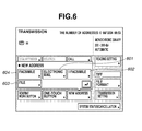
- Fig. 6 illustrates a screen displayed on the LCD display unit 2013 of the operation unit 2012. On the screen illustrated in Fig. 6 are displayed an electronic mail button 601, an I facsimile button 602, a file button 603, and a facsimile button 604.
- the operation unit component 3001 notifies the transmission management component 3003 of the communication system corresponding to the specified button.
- the transmission management component 3003 recognizes the communication system of which the operation unit component 3001 notifies the transmission management component 3003 and starts the component corresponding to the communication system.
- the LCD display unit 2013 displays a facsimile screen illustrated in Fig. 8 .
- step S701 the operation unit component 3001 determines whether a key input is performed by the user of the copying machine 1001. If the operation unit component 3001 determines that a key input is performed (YES in step S701), the processing proceeds to step S702.
- step S702 the operation unit component 3001 determines whether the input key is the menu key 2016. If the operation unit component 3001 determines that the input key is the menu key 2016 (YES in step S702), the processing in Fig. 7 is ended. If the operation unit component 3001 determines that the input key is not the menu key 2016 (NO in step S702), the processing proceeds to step S703.
- step S703 the operation unit component 3001 determines whether the input key is a numeric key. If the operation unit component 3001 determines that the input key is the numeric key (YES in step S703), the processing proceeds to step S704. If the operation unit component 3001 determines that the input key is not the numeric key (NO in step S703), the processing proceeds to step S705.
- step S704 the operation unit component 3001 notifies the facsimile transmission component 3006 of the numeric value corresponding to the numeric key input in step S703 via the transmission management component 3003.
- the facsimile transmission component 3006 adds the numeric value of which the operation unit component 3001 notifies the facsimile transmission component 3006 to the end of a transmission address number 901 illustrated in Fig. 9 .
- the transmission address number 901 is stored in the RAM 2002.
- the transmission address number stored in the transmission address number 901 is "123" and the numeric value corresponding to the numeric key input in step S703 is "4," for example, "1234" is newly stored as the transmission address number in the transmission address number 901.
- the transmission address number stored in the transmission address number 901 is displayed on 801 in Fig. 8 .
- step S705 the operation unit component 3001 determines whether the input (received) key is a start key 2014. If the operation unit component 3001 determines that the input key is the start key 2014 (YES in step S705), the processing proceeds to step S706. If the operation unit component 3001 determines that the input key is not the start key 2014 (NO in step S705), the process corresponding to the input key is executed in step S710.
- step S706 the facsimile transmission component 3006 determines whether a facsimile can be transmitted. If the facsimile transmission component 3006 determines that a facsimile can be transmitted (YES in step S706), the processing proceeds to step S707. More specifically, the facsimile transmission component 3006 determines whether the transmission address number 901 does not store any numeric value (empty). If no numeric value is stored, the facsimile transmission component 3006 determines that a facsimile cannot be transmitted.
- Other information may be used as a condition for determining whether a facsimile can be transmitted. It can be determined that a facsimile cannot be transmitted in a case where a document is not placed on the scanner 2070, for example. Alternatively, the state of the modem 2050 is determined and if the modem 2050 is not connected to the public line 1008, it can be determined that a facsimile cannot be transmitted.
- step S707 the facsimile transmission component 3006 instructs the scanner component 3004 to cause the scanner 2070 to read a document via the transmission management component 3003.
- the scanner 2070 reads the document to acquire image data and causes the image buffer 902 of the RAM 2002 to store the acquired image data.
- step S708 the facsimile transmission component 3006 controls the modem 2050 in such a manner that the image compression unit 2040 compresses the image data stored in the image buffer 902 to the image data in a facsimile format and transmits the compressed data to the transmission address number 901.
- step S709 the facsimile transmission component 3006 controls the RAM 2002 in such a manner that the transmission address number 901 stored in the RAM 2002 is deleted from the RAM 2002. This allows preventing image data from being transmitted again to the address to which the data have already transmitted when image data is transmitted to the address information (transmission address number) associated with the facsimile communication system by inputting again the start key 2014.
- the image data which have to be made secret can be prevented from being leaked outside a company due to the erroneously transmission of image data to the same address as that of the previous transmission.
- a mail address input screen 8004 illustrated in Fig. 10 is displayed on the LCD display unit 2013.
- the mail address input screen 8004 illustrated in Fig. 10 is displayed.
- the process executed by the operation unit component 3001, the transmission management component 3003, and the mail/I facsimile transmission component 3008 in a case where the I facsimile button 602 is specified by the user on the screen in Fig. 6 is similar to that in Fig. 11 , so that further description thereof is omitted herein.
- step S1101 the operation unit component 3001 determines whether a key input is performed by the user of the copying machine 1001. If the operation unit component 3001 determines that a key input is performed (YES in step S1101), the processing proceeds to step S1102.
- step S1102 the operation unit component 3001 determines whether the input key is a cancel key 8005. If the operation unit component 3001 determines that the input key is the cancel key 8005 (YES in step S1102), the processing in Fig. 11 is ended. If the operation unit component 3001 determines that the input key is not the cancel key 8005 (NO in step S1102), the processing proceeds to step S1103.
- step S1103 the operation unit component 3001 determines whether the input key is a soft key. If the operation unit component 3001 determines that the input key is the soft key (YES in step S1103), the processing proceeds to step S1104. If the operation unit component 3001 determines that the input key is not the soft key (NO in step S1103), the processing proceeds to step S1105.
- the soft key refers to buttons such as "a”, “b”, “@”, and others displayed on the mail address input screen 8004 illustrated in Fig. 10 .
- the user presses these buttons to cause the operation unit component 3001 to notify the mail/I facsimile transmission component 3008 of the code corresponding to the pressed button ("a" for example) via the transmission management component 3003.
- step S1104 the operation unit component 3001 notifies the mail/I facsimile transmission component 3008 of the code corresponding to the soft key input in step S1103 via the transmission management component 3003.
- the mail/I facsimile transmission component 3008 adds the code of which the operation unit component 3001 notifies the mail/I facsimile transmission component 3008 to the end of a transmission address 904 illustrated in Fig. 9 .
- the transmission address 904 is stored in the RAM 2002.
- the transmission address stored in the transmission address 904 is "abc@abc.co.jp" and the code corresponding to the soft key input in step S1103 is "p," for example, " abc@abc.co.jp" is stored as the transmission address in 904.
- the transmission address stored in the transmission address 904 is displayed on field 802 in Fig. 8 .
- the flow chart in Fig. 7 is executed to display the transmission address number 901 on field 801 in Fig. 8 if the transmission address number 901 is already stored.
- the user inputs the start key 2014 with the transmission address displayed on both fields 801 and 802 in Fig. 8 to simultaneously transmit the image data acquired by the scanner 2070 in both the facsimile and the electronic mail communication system.
- a multi-address transmission is performed to a plurality of addresses corresponding to a plurality of communication systems.
- step S1105 the operation unit component 3001 determines whether the input key is the start key 2014. If the operation unit component 3001 determines that the input key is the start key 2014 (if transmission instruction is received) (YES in step S1105), the processing proceeds to step S1106. If the operation unit component 3001 determines that the input key is not the start key 2014 (NO in step S1105), the process corresponding to the input key is executed in step S1109.
- step S1106 the mail/I facsimile transmission component 3008 determines whether an electronic mail can be transmitted. If the mail/I facsimile transmission component 3008 determines that an electronic mail can be transmitted (YES in step S1106), the processing proceeds to step S1107. More specifically, the mail/I facsimile transmission component 3008 determines whether the transmission address 904 stored in the RAM 2002 does not store any code (empty). If no code is stored, the mail/I facsimile transmission component 3008 determines that an electronic mail cannot be transmitted.
- Other information may be used as a condition for determining whether an electronic mail can be transmitted. It can be determined that an electronic mail cannot be transmitted in a case where a document is not placed on the scanner 2070, for example. Alternatively, the state of the network I/F 2010 is determined and if the network I/F 2010 is not connected to the LAN 1006, it can be determined that an electronic mail cannot be transmitted.
- step S1107 the mail/I facsimile transmission component 3008 instructs the scanner component 3004 to cause the scanner 2070 to read a document via the transmission management component 3003.
- the scanner 2070 reads the document to acquire image data and causes the image buffer 902 of the RAM 2002 to store the acquired image data.
- step S1108 the mail/I facsimile transmission component 3008 causes the image compression unit 2040 to compress the image data stored in the image buffer 902 to the image data in a predetermined format (PDF format, for example) and transmits the compressed data to the transmission address 904.
- a predetermined format PDF format, for example
- the image data is transmitted as a file attached to an electronic mail.
- the image compression unit 2040 may be controlled so that the user can optionally select the format of an attached file such as PDF, JPEG, and others and change data to those in the selected format.
- the reason the electronic mail communication system is configured not to delete the transmission address 904 is that communication using the electronic mail communication system can prevent an electronic mail from being transmitted to an address inappropriate for destination by an in-house mail server restricting transmission (only to a predetermined address, for example).
- a transmission protocol selection screen 806 illustrated in Fig. 13 is displayed on the LCD display unit 2013.
- step S1200 the operation unit component 3001 receives the selection of a transmission protocol by the user of the copying machine 1001.
- a transmission protocol can be selected from any of a Web-based Distributed Authoring and Versioning (WEBDAV) 8007, a Server Message Block (SMB) 8008, and a File Transfer Protocol (FTP) 8009.
- WEBDAV Web-based Distributed Authoring and Versioning
- SMB Server Message Block
- FTP File Transfer Protocol
- the transmission protocol selected by the user is stored as a transmission protocol 903 in the RAM 2002.
- step S1201 the operation unit component 3001 determines whether a key input is performed by the user of the copying machine 1001. If the operation unit component 3001 determines that a key input is performed (YES in step S1201), the processing proceeds to step S1202.
- step S1202 the operation unit component 3001 determines whether the input key is a cancel key 8010. If the operation unit component 3001 determines that the input key is the cancel key 8010 (YES in step S1202), the processing in Fig. 12 is ended. If the operation unit component 3001 determines that the input key is not the cancel key 8010 (NO in step S1202), the processing proceeds to step S1203.
- step S1203 the operation unit component 3001 determines whether the input key is a soft key. If the operation unit component 3001 determines that the input key is the soft key (YES in step S1203), the processing proceeds to step S1204. If the operation unit component 3001 determines that the input key is not the soft key (NO in step S1203), the processing proceeds to step S1205.
- the soft key refers to buttons such as “a”, “b”, and others (same as those illustrated in Fig. 10 ) displayed on a screen (not illustrated) displayed by inputting keys 8011 to 8014 in Fig. 14 .
- the user presses these buttons to cause the operation unit component 3001 to notify the database storage component 3007 of the code corresponding to the pressed button ("a" for example) via the transmission management component 3003.
- step S1204 the operation unit component 3001 notifies the database storage component 3007 of the code corresponding to the soft key input in step S1203 via the transmission management component 3003.
- the database storage component 3007 adds the code of which the operation unit component 3001 notifies the database storage component 3007 to the end of a transmission address 904 illustrated in Fig. 9 .
- the transmission address 904 is stored in the RAM 2002.
- the transmission address stored in the transmission address 904 is displayed on the field 802 in Fig. 8 . If an electronic mail or other addresses for transmitting files are already input in field 802, other fields (not illustrated) may be provided under field 802 to display an address for transmitting a file stored in the transmission address 904.
- step S1205 the operation unit component 3001 determines whether the input key is the start key 2014. If the operation unit component 3001 determines that the input key is the start key 2014 (YES in step S1205), the processing proceeds to step S1206. If the operation unit component 3001 determines that the input key is not the start key 2014 (NO in step S1205), the processing corresponding to the input key is executed in step S1209.
- step S1206 the database storage component 3007 determines whether a file can be transmitted. If the database storage component 3007 determines that a file can be transmitted (YES in step S1206), the processing proceeds to step S1207.
- the database storage component 3007 determines whether the transmission address 904 stored in the RAM 2002 stores no code (empty). If no code is stored, the database storage component 3007 determines that a file cannot be transmitted.
- Other information may be used as a condition for determining whether a file can be transmitted. It can be determined that a file cannot be transmitted in a case where a document is not placed on the scanner 2070, for example. Alternatively, the state of the network I/F 2010 is determined and if the network I/F 2010 is not connected to the LAN 1006, it can be determined that a file cannot be transmitted.
- step S1207 the database storage component 3007 instructs the scanner component 3004 to cause the scanner 2070 to read a document via the transmission management component 3003.
- the scanner 2070 reads the document to acquire image data and causes the image buffer 902 of the RAM 2002 to store the acquired image data.
- the database storage component 3007 causes the image compression unit 2040 to compress the image data stored in the image buffer 902 to the image data in a predetermined format (PDF format, for example), and transmits the compressed data to the transmission address 904.
- PDF format a predetermined format
- the image compression unit 2040 may be controlled so that the user can optionally select the format of image data such as PDF, JPEG, and others, and change data to those in the selected format.
- the reason why the file transfer communication system is configured not to delete the transmission address 904 is that communication using the file transfer communication system can prevent a file from being transmitted to an address inappropriate for destination by an in-house server restricting transmission.
- the facsimile transmission component 3006 controls the RAM 2002 so as to delete the transmission address number 901 stored in the RAM 2002 from the RAM 2002 after transmission.
- mail/I facsimile transmission component 3008 controls the RAM 2002 so as to keep the transmission address 904 stored in the RAM 2002 without deleting the transmission address 904 from the RAM 2002 after transmission.
- the database storage component 3007 operates in a similar manner as the mail/I facsimile transmission component 3008.
- the start key 2014 is input again into the address information (transmission address number) associated with the facsimile communication system to enable preventing image data from being transmitted to the address to which the image data are already transmitted when the image data are transmitted again. Accordingly, the image data which have to be made secret can be prevented from being leaked due to the erroneous transmission of image data to the same address as that of the previous transmission.
- the electronic mail communication system and the file transfer communication system are capable of performing transmission to the transmission address 904 kept stored even after the transmission process is ended.
- the transmission address number 901 for the facsimile communication system and the transmission address 904 for the electronic mail communication system or the file transfer communication system are stored in the RAM 2002, and the transmission process (multi-address transmission) is executed. Then, the transmission address number 901 is deleted from the RAM 2002, but the transmission address 904 is not deleted therefrom.
- the transmission address number 901 for the facsimile communication system and the transmission address 904 for the electronic mail communication system or the file transfer communication system are stored in the RAM 2002 and the transmission process (multi-address transmission) is executed. Then, both of the transmission address number 901 and the transmission address 904 are deleted from the RAM 2002.
- the second embodiment can prevent the number of addresses for the multi-address transmission from being decreased at the time of transmission to the same address as that of the previous transmission.
- the process executed by the operation unit component 3001, the transmission management component 3003, and the facsimile transmission component 3006 in a case where the facsimile button 604 is specified by the user on the screen in Fig. 6 is similar to that in the flow chart in Fig. 7 , so that further description thereof is omitted herein.
- the flow chart in Fig. 15 is an example of a modification of that in Fig. 11 . Since steps 1101 to 1109 are similar to those having the same reference signs in the flow chart in Fig. 11 , description thereof is omitted herein.
- the flow chart in Fig. 15 is different from that in Fig. 11 in that steps S1501 and S1502 are added to Fig. 11 . Those steps are described below.
- step S1501 the transmission management component 3003 determines whether the electronic mail transmission process in step S1108 is a multi-address transmission including a facsimile. More specifically, the transmission management component 3003 determines whether a facsimile number is stored in the transmission address number 901 when the start key 2014 is pressed in step S1105 and a facsimile is transmitted to the facsimile number in step S708 in Fig. 7 . If the determination is "YES,” the processing proceeds to step S1502. If the determination is "NO,” the processing returns to step S1101.
- step S1502 the mail/I facsimile transmission component 3008 deletes the code stored in the transmission address 904 from the RAM 2002.
- the flow chart in Fig. 16 is an example of a modification of that in Fig. 12 . Since steps 1200 to 1209 are similar to those having the same reference signs in the flow chart in Fig. 12 , description thereof is omitted herein.
- the flow chart in Fig. 16 is different from that in Fig. 12 in that steps S1601 and S1602 are added to Fig. 12 . Those steps are described below.
- step S1601 the transmission management component 3003 determines whether the file transmission process in step S1208 is a multi-address transmission including a facsimile. More specifically, the transmission management component 3003 determines whether the facsimile number is stored in the transmission address number 901 when the start key 2014 is pressed in step S1205 and a facsimile is transmitted to the facsimile number in step S708 in Fig. 7 . If the determination is "YES,” the processing proceeds to step S1602. If the determination is "NO,” the processing returns to step S1201.
- step S1602 the database storage component 3007 deletes the code stored in the transmission address 904 from the RAM 2002.
- the transmission address number 901 for the facsimile communication system and the transmission address 904 for the electronic mail communication system or the file transfer communication system are stored in the RAM 2002 and the transmission process (multi-address transmission) is executed. Then, both of the transmission address number 901 and the transmission address 904 are deleted from the RAM 2002.
- the second embodiment can prevent the number of addresses for the multi-address transmission from being decreased at the time of transmission to the same address as that of the previous transmission.
- the transmission address 904 for the electronic mail communication system is stored in the RAM 2002 and the transmission process is executed. The, the transmission address 904 is not deleted therefrom.
- the transmission address 904 is deleted from the RAM 2002 so that the address low in reliability even for the electronic mail communication system is not used as the same address as that of the previous transmission. According to third embodiment, it is possible not to use the address low in reliability even for the electronic mail communication system as re-transmission.
- the process executed by the operation unit component 3001, the transmission management component 3003, and the facsimile transmission component 3006 in a case where the facsimile button 604 is specified by the user on the screen in Fig. 6 is similar to that in the flow chart in Fig. 7 , so that description thereof is omitted herein.
- the process executed by the operation unit component 3001, the transmission management component 3003, and the database storage component 3007 in a case where the file button 603 is specified by the user on the screen in Fig. 6 is similar to that in the flow chart in Fig. 12 , so that description thereof is omitted herein.
- the flow chart in Fig. 17 is an example of a modification of that in Fig. 11 . Since steps 1101 to 1109 are similar to those having the same reference signs in the flow chart in Fig. 11 , description thereof is omitted herein.
- the flow chart in Fig. 17 is different from that in Fig. 11 in that steps S1701, S1702, and S1703 are added to Fig. 11 . Those steps are described below.
- step S1701 the mail/I facsimile transmission component 3008 determines whether the transmission address 904 used for the electronic mail transmission process in step S1108 is already registered as a reliable address.
- the reliable address is registered by the user via the screen illustrated in Fig. 18 and the registered transmission address is stored in the RAM 2002.
- step S1702 the mail/I facsimile transmission component 3008 determines whether the transmission address 904 used for the electronic mail transmission process in step S1108 has the same domain as that to which the copying machine 1001 belongs. If the transmission address 904 has the same domain (YES in step S1702), the processing proceeds to step S1101. If the transmission address 904 does not have the same domain (NO in step S1702), the processing proceeds to step S1703.
- step S1703 the mail/I facsimile transmission component 3008 deletes the code stored in the transmission address 904 from the RAM 2002.
- the transmission address 904 is deleted from the RAM 2002 so that the address low in reliability even for the electronic mail communication system is not used for re-transmission. According to third embodiment, it is possible not to use the address low in reliability even for the electronic mail communication system as re-transmission.
- aspects of the present invention can also be realized by a computer of a system or apparatus (or devices such as a CPU or MPU) that reads out and executes a program recorded on a memory device to perform the functions of the above-described embodiments, and by a method, the steps of which are performed by a computer of a system or apparatus by, for example, reading out and executing a program recorded on a memory device to perform the functions of the above-described embodiments.
- the program is provided to the computer for example via a network or from a recording medium of various types serving as the memory device (e.g., computer-readable medium) .
- the system or apparatus, and the recording medium where the program is stored are included as being within the scope of the present invention.
Abstract
Description
- The present invention relates to a communication apparatus and a control method of the communication apparatus.
- In a communication apparatus for transmitting image data to an external device, Japanese Patent Application Laid-Open No.
2003-51927 - According to Japanese Patent Application Laid-Open No.
2003-51927 - The present invention is directed to a communication apparatus and a control method of the communication apparatus capable of storing an address so that image data is transmitted to the same address as that of the previous transmission and preventing the image data from being erroneously transmitted to the address associated with a predetermined communication system.
- According to a first aspect of the present invention, there is provided a communication apparatus as specified in
claims 1 to 4. According to a second aspect of the present invention, there is provided a method for controlling a communication apparatus as specified inclams 5. - Further features and aspects of the present invention will become apparent from the following detailed description of embodiments with reference to the attached drawings.
- The accompanying drawings, which are incorporated in and constitute a part of the specification, illustrate embodiments, features, and aspects of the invention and, together with the description, serve to explain the principles of the invention.
-
Fig. 1 is a schematic diagram illustrating a configuration of a network. -
Fig. 2 is a block diagram illustrating a configuration of the principal part of acopying machine 1001. -
Fig. 3 illustrates functional blocks of a configuration of software. -
Fig. 4 is an address information management table managed by anaddress management component 3002. -
Figs. 5A and 5B illustrate a configuration of anoperation unit 2012. -
Fig. 6 illustrates a screen displayed on anLCD display unit 2013 of theoperation unit 2012. -
Fig. 7 is a flow chart executed in a case where afacsimile button 604 is specified by a user. -
Fig. 8 illustrates a screen for a facsimile. -
Fig. 9 illustrates data stored in aRAM 2002. -
Fig. 10 is an input screen for a mail address. -
Fig. 11 is a flow chart executed in a case where anelectronic mail button 601 is specified by the user. -
Fig. 12 is a flow chart executed in a case where afile button 603 is specified by the user. -
Fig. 13 illustrates a transmission protocol selection screen. -
Fig. 14 is an input screen for a file transmission destination. -
Fig. 15 is a flow chart executed in a case where theelectronic mail button 601 is specified by the user. -
Fig. 16 is a flow chart executed in a case where thefile button 603 is specified by the user. -
Fig. 17 is a flow chart executed in a case where theelectronic mail button 601 is specified by the user. -
Fig. 18 illustrates a screen for registering a reliable address. - Various embodiments, features, and aspects of the invention will be described in detail below with reference to the drawings.
- The same components are given the same reference numerals and further description thereof is omitted. Constitutional blocks required for the present embodiment are described below and then a detailed process is described.
-
Fig. 1 is a schematic diagram illustrating a configuration of a network containing a communication apparatus according to a first embodiment of the present invention. In the present embodiment, a copying machine having a facsimile function and a data transmission function as a communication apparatus is described. - As illustrated in
Fig. 1 , acopying machine 1001 is connected to aLAN 1006 of the Ethernet (registered trademark) along with aprinter 1002, afacsimile machine 1003, a database/mail server 1004, and aclient computer 1005. Furthermore, thecopying machine 1001 is connected to apublic line 1008 along with afacsimile machine 1007. - The
copying machine 1001 has not only a copy function and a facsimile function but also a data transmission function of reading an image on a document and transmitting the read image data to each apparatus on theLAN 1006. Theprinter 1002 is capable of receiving data read by thecopying machine 1001 and transmitting the received data via theLAN 1006. - The
facsimile machine 1003 is capable of receiving data read by thecopying machine 1001 and transmitting the received data via theLAN 1006. The database/mail server 1004 is a server apparatus with a function of receiving data read by thecopying machine 1001 via theLAN 1006, storing the received data, and transmitting data as an electronic mail. - The
client computer 1005 is connected to the database/mail server 1004 and capable of acquiring a desired data from the database/mail server 1004 and displaying the data thereon. Theclient computer 1005 is also capable of receiving the data read by thecopying machine 1001 via theLAN 1006, and processing and editing the received data. - The
facsimile machine 1007 is capable of receiving the data read by thecopying machine 1001 via thepublic line 1008 and printing the received data. - The configuration of the principal part of the
copying machine 1001 is described below with reference toFig. 2. Fig. 2 is a block diagram illustrating the configuration of the principal part of thecopying machine 1001 inFig. 1 . - As illustrated in
Fig. 2 , thecopying machine 1001 is equipped with acontroller unit 2000 connected to ascanner 2070 and aprinter 2095. Thecontroller unit 2000 performs control for realizing a copy function in which the image data read by thescanner 2070 is printed by theprinter 2095, and connect thecopying machine 1001 with aLAN 1006 and a public line (WAN) 2051. Thereby, thecopying machine 1001 performs control for inputting and outputting image information and device information. - The
controller unit 2000 includes aCPU 2001 which boots an operation system (OS) using a boot program stored in aROM 2003. An application program stored in a hard disk drive HDD) 2004 is executed on the OS to execute various processing operations. - A
RAM 2002 is used as a work area of theCPU 2001. TheRAM 2002 provides not only a work area, but also an image memory area for temporarily storing image data. The HDD 2004 stores image data with an application program. - The
CPU 2001 is connected to theROM 2003 and theRAM 2002 via asystem bus 2007. TheCPU 2001 is also connected to an operation unit interface (operation unit I/F) 2006, a network interface (network I/F) 2010, amodem 2050, and an image bus interface (image bus I/F) 2005. - The operation unit I/
F 2006 is an interface with anoperation unit 2012 having a touch panel, and outputs image data to be displayed on theoperation unit 2012 to theoperation unit 2012. The operation unit I/F 2006 sends information input by a user through theoperation unit 2012 to theCPU 2001. - The network I/
F 2010 is connected to theLAN 1006 and exchanges information with each apparatus on theLAN 1006 via theLAN 1006. Themodem 2050 is connected to thepublic line 2051 and exchanges information via thepublic line 2051. - The image bus I/F 2005 is a bus bridge for connecting the
system bus 2007 with animage bus 2008 for transferring image data at a high speed to convert data structure. Theimage bus 2008 is composed of a PCI bus or an IEEE1394. On theimage bus 2008 are provided a raster image processor (hereinafter referred to as RIP) 2060, a device I/F 2020, a scannerimage processing unit 2080, a printerimage processing unit 2090, animage rotation unit 2030, and animage compression unit 2040. - The
RIP 2060 is a processor for rasterizing a PDL code into a bit map image. The device I/F 2020 is connected to thescanner 2070 and theprinter 2095 to perform synchronous/asynchronous conversion of image data. The scannerimage processing unit 2080 subjects input image data to correction, processing, and editing. - The printer
image processing unit 2090 subjects print input image data to the correction of a printer and the conversion of resolution. Theimage rotation unit 2030 rotates image data. Theimage compression unit 2040 compresses multi-valued image data into JPEG data and binary image data to JBIG, MMR, or MH data and performs the decompression process thereof. - The configuration of the
operation unit 2012 illustrated inFig. 1 is described below with reference toFigs. 5A and 5B . -
Fig. 5A is a plan view illustrating the configuration of theoperation unit 2012 illustrated inFig. 1 . - An
LCD display unit 2013 is configured such that a touch panel sheet is stuck on an LCD. TheLCD display unit 2013 displays the operation screen of the copyingmachine 1001. When a key displayed on the operation screen is pressed by an operator (user) of the copyingmachine 1001, theLCD display unit 2013 informs theCPU 2001 of thecontroller unit 2000 of information about position thereof. - A
start key 2014 is used to start an operation of reading a document image. At the center portion of thestart key 2014 is provided with a green andred LED 2018, and the color thereof indicates a state as to whether the start key 2014 can be used. - A
stop key 2015 is operated to stop the operation. Amenu key 2016 is operated to display a menu. Anumeric keypad 2019 includes numeric keys from a zero key 4010 to a nine key 4019 as illustrated in detail inFig. 5B . - The
numeric keypad 2019 further includes a reset key 4001, aguide key 4002, auser mode key 4003, an asterisk (*)key 4004, a pound sign (#)key 4005, anID key 4006, and a clear (C)key 4007. Pressing each key causes the operation unit I/F 2006 to generate a predetermined key code, and to display a screen according to the key code on a screen in operation via thesystem bus 2007. - The data transmission function of the copying
machine 1001 is described below with reference toFigs. 3 and4 . -
Fig. 3 illustrates functional blocks of software for realizing the facsimile and the data transmission function of the copyingmachine 1001 illustrated inFig. 1 .Fig. 4 illustrates an address information management table managed by anaddress management component 3002 inFig. 3 . - The facsimile function and the data transmission function of the copying
machine 1001 are realized by theCPU 2001 executing the application program stored in theHDD 2004. The functional blocks of the data transmission function realized by the execution include anoperation unit component 3001, theaddress management component 3002, atransmission management component 3003, and atransfer management component 3011, as illustrated inFig. 3 . - The
address management component 3002 stores and manages a management table in which address information for identifying an address (apparatus on the LAN 1006) to which data is transmitted via the network I/F 2010 and an address (apparatus on the public line) to which data is transmitted via themodem 2050 is written. - Specifically, the management table is the one whose contents can be rewritten by the user inputting via the
operation unit 2012, and is stored in theHDD 2004. As illustrated inFig. 4 , a management number (Index ID), an address name (Name), communication type (Type), and transmission address (Address) are written in the management table. - The communication type (Type) in the table indicates the attribute of a transmission job. In the present embodiment, "fax," "print," "database," and "mail" or "ifax" represent a facsimile job, a print job, a database job, and an electronic mail/I facsimile job, respectively.
- The
operation unit component 3001 acquires address information from theaddress management component 3002 and displays the acquired information on theoperation unit 2012. - The
transmission management component 3003 is connected to ascanner component 3004, aprint component 3005, afacsimile transmission component 3006, adatabase storage component 3007, and a mail/Ifacsimile transmission component 3008. Thescanner component 3004 controls the operation of thescanner 2070 based on a process command issued from thetransmission management component 3003. - The
facsimile transmission component 3006 controls a data transmission operation via themodem 2050 based on a process command issued from thetransmission management component 3003. Theprint component 3005 controls the operation of transmitting data to theprinter 1002 via the network I/F 2010 based on a process command issued from thetransmission management component 3003. - The
database storage component 3007 controls the operation of transmitting data to the database/mail server 1004 via the network I/F 2010 based on a process command issued from thetransmission management component 3003. The mail/Ifacsimile transmission component 3008 controls the operation of transmitting data to the database/mail server 1004 via the network I/F 2010 based on a process command issued from thetransmission management component 3003. - The
transmission management component 3003 issues a process command to each of thecomponents 3005 to 3008 based on address information selected by theoperation unit component 3001. - When the address of a facsimile job is selected using the
operation unit component 3001, for example, thetransmission management component 3003 issues a process command for thescanner component 3004 to read a document image. - The
transmission management component 3003 issues a process command for thefacsimile transmission component 3006 to transmit the read image data to the selected address by facsimile. Thereby, the image data read by thescanner 2070 are transmitted to thefacsimile machines - When the address of a print job, a database job, or an electronic mail/I facsimile job are selected by using the
operation unit component 3001, a process command is issued to theprint component 3005, thedatabase storage component 3007, or the mail/Ifacsimile transmission component 3008. - The image data read by the
scanner 2070 is transmitted from theprint component 3005, thedatabase storage component 3007, or the mail/Ifacsimile transmission component 3008 to theprinter 1002 or the database/mail server 1004. - The facsimile image and the I facsimile image transmitted from the
facsimile machine 1003 and theclient computer 1005 are received by thefacsimile reception component 3009 and an Ifacsimile reception component 3010 via the network I/F 2010 respectively. - The received facsimile image and I facsimile image are transferred to the
transmission management component 3003 by thetransfer management component 3011 based on information of theaddress management component 3002. - The facsimile image transmitted from the
facsimile machine 1007 is received by thefacsimile reception component 3009 via themodem 2050. The received facsimile image is transferred to thetransmission management component 3003 by atransfer management component 3011 based on information of theaddress management component 3002. - The transmission process executed by the
facsimile transmission component 3006, thedatabase storage component 3007, and the mail/Ifacsimile transmission component 3008 is described below. -
Fig. 6 illustrates a screen displayed on theLCD display unit 2013 of theoperation unit 2012. On the screen illustrated inFig. 6 are displayed anelectronic mail button 601, anI facsimile button 602, afile button 603, and afacsimile button 604. - If any of the
buttons 601 to 604 is specified by the user, theoperation unit component 3001 notifies thetransmission management component 3003 of the communication system corresponding to the specified button. Thetransmission management component 3003 recognizes the communication system of which theoperation unit component 3001 notifies thetransmission management component 3003 and starts the component corresponding to the communication system. - The process executed by the
operation unit component 3001, thetransmission management component 3003, and thefacsimile transmission component 3006 in a case where thefacsimile button 604 is specified by the user on the screen inFig. 6 is described below with reference to a flow chart illustrated inFig. 7 . - In a case where the
facsimile button 604 is specified by the user, theLCD display unit 2013 displays a facsimile screen illustrated inFig. 8 . - In step S701, the
operation unit component 3001 determines whether a key input is performed by the user of the copyingmachine 1001. If theoperation unit component 3001 determines that a key input is performed (YES in step S701), the processing proceeds to step S702. - In step S702, the
operation unit component 3001 determines whether the input key is themenu key 2016. If theoperation unit component 3001 determines that the input key is the menu key 2016 (YES in step S702), the processing inFig. 7 is ended. If theoperation unit component 3001 determines that the input key is not the menu key 2016 (NO in step S702), the processing proceeds to step S703. - In step S703, the
operation unit component 3001 determines whether the input key is a numeric key. If theoperation unit component 3001 determines that the input key is the numeric key (YES in step S703), the processing proceeds to step S704. If theoperation unit component 3001 determines that the input key is not the numeric key (NO in step S703), the processing proceeds to step S705. - In step S704, the
operation unit component 3001 notifies thefacsimile transmission component 3006 of the numeric value corresponding to the numeric key input in step S703 via thetransmission management component 3003. Thefacsimile transmission component 3006 adds the numeric value of which theoperation unit component 3001 notifies thefacsimile transmission component 3006 to the end of atransmission address number 901 illustrated inFig. 9 . - The
transmission address number 901 is stored in theRAM 2002. In a case where the transmission address number stored in thetransmission address number 901 is "123" and the numeric value corresponding to the numeric key input in step S703 is "4," for example, "1234" is newly stored as the transmission address number in thetransmission address number 901. The transmission address number stored in thetransmission address number 901 is displayed on 801 inFig. 8 . - In step S705, the
operation unit component 3001 determines whether the input (received) key is astart key 2014. If theoperation unit component 3001 determines that the input key is the start key 2014 (YES in step S705), the processing proceeds to step S706. If theoperation unit component 3001 determines that the input key is not the start key 2014 (NO in step S705), the process corresponding to the input key is executed in step S710. - In step S706, the
facsimile transmission component 3006 determines whether a facsimile can be transmitted. If thefacsimile transmission component 3006 determines that a facsimile can be transmitted (YES in step S706), the processing proceeds to step S707. More specifically, thefacsimile transmission component 3006 determines whether thetransmission address number 901 does not store any numeric value (empty). If no numeric value is stored, thefacsimile transmission component 3006 determines that a facsimile cannot be transmitted. - Other information may be used as a condition for determining whether a facsimile can be transmitted. It can be determined that a facsimile cannot be transmitted in a case where a document is not placed on the
scanner 2070, for example. Alternatively, the state of themodem 2050 is determined and if themodem 2050 is not connected to thepublic line 1008, it can be determined that a facsimile cannot be transmitted. - In step S707, the
facsimile transmission component 3006 instructs thescanner component 3004 to cause thescanner 2070 to read a document via thetransmission management component 3003. Thescanner 2070 reads the document to acquire image data and causes theimage buffer 902 of theRAM 2002 to store the acquired image data. - In step S708, the
facsimile transmission component 3006 controls themodem 2050 in such a manner that theimage compression unit 2040 compresses the image data stored in theimage buffer 902 to the image data in a facsimile format and transmits the compressed data to thetransmission address number 901. - In step S709, the
facsimile transmission component 3006 controls theRAM 2002 in such a manner that thetransmission address number 901 stored in theRAM 2002 is deleted from theRAM 2002. This allows preventing image data from being transmitted again to the address to which the data have already transmitted when image data is transmitted to the address information (transmission address number) associated with the facsimile communication system by inputting again thestart key 2014. - Therefore, the image data which have to be made secret can be prevented from being leaked outside a company due to the erroneously transmission of image data to the same address as that of the previous transmission.
- The process executed by the
operation unit component 3001, thetransmission management component 3003, and the mail/Ifacsimile transmission component 3008 in a case where theelectronic mail button 601 is specified by the user on the screen illustrated inFig. 6 is described below with reference to a flow chart illustrated inFig. 11 . - In a case where the
electronic mail button 601 is specified by the user on the screen inFig. 6 , a mailaddress input screen 8004 illustrated inFig. 10 is displayed on theLCD display unit 2013. - Also in a case where the
I facsimile button 602 is specified by the user on the screen inFig. 6 , the mailaddress input screen 8004 illustrated inFig. 10 is displayed. The process executed by theoperation unit component 3001, thetransmission management component 3003, and the mail/Ifacsimile transmission component 3008 in a case where theI facsimile button 602 is specified by the user on the screen inFig. 6 is similar to that inFig. 11 , so that further description thereof is omitted herein. - In step S1101, the
operation unit component 3001 determines whether a key input is performed by the user of the copyingmachine 1001. If theoperation unit component 3001 determines that a key input is performed (YES in step S1101), the processing proceeds to step S1102. - In step S1102, the
operation unit component 3001 determines whether the input key is a cancel key 8005. If theoperation unit component 3001 determines that the input key is the cancel key 8005 (YES in step S1102), the processing inFig. 11 is ended. If theoperation unit component 3001 determines that the input key is not the cancel key 8005 (NO in step S1102), the processing proceeds to step S1103. - In step S1103, the
operation unit component 3001 determines whether the input key is a soft key. If theoperation unit component 3001 determines that the input key is the soft key (YES in step S1103), the processing proceeds to step S1104. If theoperation unit component 3001 determines that the input key is not the soft key (NO in step S1103), the processing proceeds to step S1105. - The soft key refers to buttons such as "a", "b", "@", and others displayed on the mail
address input screen 8004 illustrated inFig. 10 . The user presses these buttons to cause theoperation unit component 3001 to notify the mail/Ifacsimile transmission component 3008 of the code corresponding to the pressed button ("a" for example) via thetransmission management component 3003. - In step S1104, the
operation unit component 3001 notifies the mail/Ifacsimile transmission component 3008 of the code corresponding to the soft key input in step S1103 via thetransmission management component 3003. - The mail/I
facsimile transmission component 3008 adds the code of which theoperation unit component 3001 notifies the mail/Ifacsimile transmission component 3008 to the end of atransmission address 904 illustrated inFig. 9 . Thetransmission address 904 is stored in theRAM 2002. - In a case where the transmission address stored in the
transmission address 904 is "abc@abc.co.jp" and the code corresponding to the soft key input in step S1103 is "p," for example, " abc@abc.co.jp" is stored as the transmission address in 904. The transmission address stored in thetransmission address 904 is displayed onfield 802 inFig. 8 . - The flow chart in
Fig. 7 is executed to display thetransmission address number 901 onfield 801 inFig. 8 if thetransmission address number 901 is already stored. The user inputs the start key 2014 with the transmission address displayed on bothfields Fig. 8 to simultaneously transmit the image data acquired by thescanner 2070 in both the facsimile and the electronic mail communication system. In other words, a multi-address transmission is performed to a plurality of addresses corresponding to a plurality of communication systems. - In step S1105, the
operation unit component 3001 determines whether the input key is thestart key 2014. If theoperation unit component 3001 determines that the input key is the start key 2014 (if transmission instruction is received) (YES in step S1105), the processing proceeds to step S1106. If theoperation unit component 3001 determines that the input key is not the start key 2014 (NO in step S1105), the process corresponding to the input key is executed in step S1109. - In step S1106, the mail/I
facsimile transmission component 3008 determines whether an electronic mail can be transmitted. If the mail/Ifacsimile transmission component 3008 determines that an electronic mail can be transmitted (YES in step S1106), the processing proceeds to step S1107. More specifically, the mail/Ifacsimile transmission component 3008 determines whether thetransmission address 904 stored in theRAM 2002 does not store any code (empty). If no code is stored, the mail/Ifacsimile transmission component 3008 determines that an electronic mail cannot be transmitted. - Other information may be used as a condition for determining whether an electronic mail can be transmitted. It can be determined that an electronic mail cannot be transmitted in a case where a document is not placed on the
scanner 2070, for example. Alternatively, the state of the network I/F 2010 is determined and if the network I/F 2010 is not connected to theLAN 1006, it can be determined that an electronic mail cannot be transmitted. - In step S1107, the mail/I
facsimile transmission component 3008 instructs thescanner component 3004 to cause thescanner 2070 to read a document via thetransmission management component 3003. Thescanner 2070 reads the document to acquire image data and causes theimage buffer 902 of theRAM 2002 to store the acquired image data. - In step S1108, the mail/I
facsimile transmission component 3008 causes theimage compression unit 2040 to compress the image data stored in theimage buffer 902 to the image data in a predetermined format (PDF format, for example) and transmits the compressed data to thetransmission address 904. - The image data is transmitted as a file attached to an electronic mail. The
image compression unit 2040 may be controlled so that the user can optionally select the format of an attached file such as PDF, JPEG, and others and change data to those in the selected format. - In the transmission process in the facsimile communication system by the
facsimile transmission component 3006, although thetransmission address number 901 in theRAM 2002 is deleted after a facsimile is transmitted, such deletion is not performed in the process inFig. 11 . For this reason, if the processing is returned again to step S1101 from step S1108 and thestart key 2014 is input, an electronic mail can be transmitted to thetransmission address 904 which is kept stored even after the transmission process is ended. - The reason the electronic mail communication system is configured not to delete the
transmission address 904 is that communication using the electronic mail communication system can prevent an electronic mail from being transmitted to an address inappropriate for destination by an in-house mail server restricting transmission (only to a predetermined address, for example). - The process executed by the
operation unit component 3001, thetransmission management component 3003, and thedatabase storage component 3007 in a case where thefile button 603 is specified by the user on the screen inFig. 6 is described below with reference to a flow chart illustrated inFig. 12 . - In a case where the
file button 603 is specified by the user on the screen inFig. 6 , a transmission protocol selection screen 806 illustrated inFig. 13 is displayed on theLCD display unit 2013. - In step S1200, the
operation unit component 3001 receives the selection of a transmission protocol by the user of the copyingmachine 1001. A transmission protocol can be selected from any of a Web-based Distributed Authoring and Versioning (WEBDAV) 8007, a Server Message Block (SMB) 8008, and a File Transfer Protocol (FTP) 8009. The transmission protocol selected by the user is stored as atransmission protocol 903 in theRAM 2002. - If the transmission protocol is selected on the screen in
Fig. 13 , an input screen for a file destination illustrated inFig. 14 is displayed on theLCD display unit 2013. - In step S1201, the
operation unit component 3001 determines whether a key input is performed by the user of the copyingmachine 1001. If theoperation unit component 3001 determines that a key input is performed (YES in step S1201), the processing proceeds to step S1202. - In step S1202, the
operation unit component 3001 determines whether the input key is a cancel key 8010. If theoperation unit component 3001 determines that the input key is the cancel key 8010 (YES in step S1202), the processing inFig. 12 is ended. If theoperation unit component 3001 determines that the input key is not the cancel key 8010 (NO in step S1202), the processing proceeds to step S1203. - In step S1203, the
operation unit component 3001 determines whether the input key is a soft key. If theoperation unit component 3001 determines that the input key is the soft key (YES in step S1203), the processing proceeds to step S1204. If theoperation unit component 3001 determines that the input key is not the soft key (NO in step S1203), the processing proceeds to step S1205. - The soft key refers to buttons such as "a", "b", and others (same as those illustrated in
Fig. 10 ) displayed on a screen (not illustrated) displayed by inputtingkeys 8011 to 8014 inFig. 14 . The user presses these buttons to cause theoperation unit component 3001 to notify thedatabase storage component 3007 of the code corresponding to the pressed button ("a" for example) via thetransmission management component 3003. - In step S1204, the
operation unit component 3001 notifies thedatabase storage component 3007 of the code corresponding to the soft key input in step S1203 via thetransmission management component 3003. Thedatabase storage component 3007 adds the code of which theoperation unit component 3001 notifies thedatabase storage component 3007 to the end of atransmission address 904 illustrated inFig. 9 . - The
transmission address 904 is stored in theRAM 2002. The transmission address stored in thetransmission address 904 is displayed on thefield 802 inFig. 8 . If an electronic mail or other addresses for transmitting files are already input infield 802, other fields (not illustrated) may be provided underfield 802 to display an address for transmitting a file stored in thetransmission address 904. - In step S1205, the
operation unit component 3001 determines whether the input key is thestart key 2014. If theoperation unit component 3001 determines that the input key is the start key 2014 (YES in step S1205), the processing proceeds to step S1206. If theoperation unit component 3001 determines that the input key is not the start key 2014 (NO in step S1205), the processing corresponding to the input key is executed in step S1209. - In step S1206, the
database storage component 3007 determines whether a file can be transmitted. If thedatabase storage component 3007 determines that a file can be transmitted (YES in step S1206), the processing proceeds to step S1207. - More specifically, the
database storage component 3007 determines whether thetransmission address 904 stored in theRAM 2002 stores no code (empty). If no code is stored, thedatabase storage component 3007 determines that a file cannot be transmitted. - Other information may be used as a condition for determining whether a file can be transmitted. It can be determined that a file cannot be transmitted in a case where a document is not placed on the
scanner 2070, for example. Alternatively, the state of the network I/F 2010 is determined and if the network I/F 2010 is not connected to theLAN 1006, it can be determined that a file cannot be transmitted. - In step S1207, the
database storage component 3007 instructs thescanner component 3004 to cause thescanner 2070 to read a document via thetransmission management component 3003. Thescanner 2070 reads the document to acquire image data and causes theimage buffer 902 of theRAM 2002 to store the acquired image data. - In step S1208, the
database storage component 3007 causes theimage compression unit 2040 to compress the image data stored in theimage buffer 902 to the image data in a predetermined format (PDF format, for example), and transmits the compressed data to thetransmission address 904. Theimage compression unit 2040 may be controlled so that the user can optionally select the format of image data such as PDF, JPEG, and others, and change data to those in the selected format. - In the transmission process in the facsimile communication system by the
facsimile transmission component 3006, although thetransmission address number 901 in theRAM 2002 is deleted after the facsimile is transmitted, such deletion is not performed in the process inFig. 12 . For this reason, if the processing is returned to step S1201 from step S1208 and thestart key 2014 is input, a file can be transmitted to thetransmission address 904 which is kept stored even after the transmission process is ended. - The reason why the file transfer communication system is configured not to delete the
transmission address 904 is that communication using the file transfer communication system can prevent a file from being transmitted to an address inappropriate for destination by an in-house server restricting transmission. - As described above, the
facsimile transmission component 3006 controls theRAM 2002 so as to delete thetransmission address number 901 stored in theRAM 2002 from theRAM 2002 after transmission. On the other hand, mail/Ifacsimile transmission component 3008 controls theRAM 2002 so as to keep thetransmission address 904 stored in theRAM 2002 without deleting thetransmission address 904 from theRAM 2002 after transmission. Thedatabase storage component 3007 operates in a similar manner as the mail/Ifacsimile transmission component 3008. - Thus, the
start key 2014 is input again into the address information (transmission address number) associated with the facsimile communication system to enable preventing image data from being transmitted to the address to which the image data are already transmitted when the image data are transmitted again. Accordingly, the image data which have to be made secret can be prevented from being leaked due to the erroneous transmission of image data to the same address as that of the previous transmission. - On the other hand, the electronic mail communication system and the file transfer communication system are capable of performing transmission to the
transmission address 904 kept stored even after the transmission process is ended. - A second embodiment of the present invention is described below.
- In the first embodiment, the
transmission address number 901 for the facsimile communication system and thetransmission address 904 for the electronic mail communication system or the file transfer communication system are stored in theRAM 2002, and the transmission process (multi-address transmission) is executed. Then, thetransmission address number 901 is deleted from theRAM 2002, but thetransmission address 904 is not deleted therefrom. - In the second embodiment, the
transmission address number 901 for the facsimile communication system and thetransmission address 904 for the electronic mail communication system or the file transfer communication system are stored in theRAM 2002 and the transmission process (multi-address transmission) is executed. Then, both of thetransmission address number 901 and thetransmission address 904 are deleted from theRAM 2002. - The second embodiment can prevent the number of addresses for the multi-address transmission from being decreased at the time of transmission to the same address as that of the previous transmission.
- The process executed by the
operation unit component 3001, thetransmission management component 3003, and thefacsimile transmission component 3006 in a case where thefacsimile button 604 is specified by the user on the screen inFig. 6 is similar to that in the flow chart inFig. 7 , so that further description thereof is omitted herein. - The process executed by the
operation unit component 3001, thetransmission management component 3003, and the mail/Ifacsimile transmission component 3008 in a case where theelectronic mail button 601 is specified by the user on the screen inFig. 6 is described below referring to the flow chart inFig. 15 . - The flow chart in
Fig. 15 is an example of a modification of that inFig. 11 . Since steps 1101 to 1109 are similar to those having the same reference signs in the flow chart inFig. 11 , description thereof is omitted herein. The flow chart inFig. 15 is different from that inFig. 11 in that steps S1501 and S1502 are added toFig. 11 . Those steps are described below. - In step S1501, the
transmission management component 3003 determines whether the electronic mail transmission process in step S1108 is a multi-address transmission including a facsimile. More specifically, thetransmission management component 3003 determines whether a facsimile number is stored in thetransmission address number 901 when thestart key 2014 is pressed in step S1105 and a facsimile is transmitted to the facsimile number in step S708 inFig. 7 . If the determination is "YES," the processing proceeds to step S1502. If the determination is "NO," the processing returns to step S1101. - In step S1502, the mail/I
facsimile transmission component 3008 deletes the code stored in thetransmission address 904 from theRAM 2002. - The process executed by the
operation unit component 3001, thetransmission management component 3003, and thedatabase storage component 3007 in a case where thefile button 603 is specified by the user on the screen inFig. 6 is described below referring to the flow chart inFig. 16 . - The flow chart in
Fig. 16 is an example of a modification of that inFig. 12 . Since steps 1200 to 1209 are similar to those having the same reference signs in the flow chart inFig. 12 , description thereof is omitted herein. The flow chart inFig. 16 is different from that inFig. 12 in that steps S1601 and S1602 are added toFig. 12 . Those steps are described below. - In step S1601, the
transmission management component 3003 determines whether the file transmission process in step S1208 is a multi-address transmission including a facsimile. More specifically, thetransmission management component 3003 determines whether the facsimile number is stored in thetransmission address number 901 when thestart key 2014 is pressed in step S1205 and a facsimile is transmitted to the facsimile number in step S708 inFig. 7 . If the determination is "YES," the processing proceeds to step S1602. If the determination is "NO," the processing returns to step S1201. - In step S1602, the
database storage component 3007 deletes the code stored in thetransmission address 904 from theRAM 2002. - As described above, in the second embodiment, the
transmission address number 901 for the facsimile communication system and thetransmission address 904 for the electronic mail communication system or the file transfer communication system are stored in theRAM 2002 and the transmission process (multi-address transmission) is executed. Then, both of thetransmission address number 901 and thetransmission address 904 are deleted from theRAM 2002. - The second embodiment can prevent the number of addresses for the multi-address transmission from being decreased at the time of transmission to the same address as that of the previous transmission.
- In the first embodiment, the
transmission address 904 for the electronic mail communication system is stored in theRAM 2002 and the transmission process is executed. The, thetransmission address 904 is not deleted therefrom. - However, it is desirable to delete the address even for the electronic mail communication system from the
RAM 2002 if the address is low in reliability. - In a third embodiment, the
transmission address 904 is deleted from theRAM 2002 so that the address low in reliability even for the electronic mail communication system is not used as the same address as that of the previous transmission. According to third embodiment, it is possible not to use the address low in reliability even for the electronic mail communication system as re-transmission. - The process executed by the
operation unit component 3001, thetransmission management component 3003, and thefacsimile transmission component 3006 in a case where thefacsimile button 604 is specified by the user on the screen inFig. 6 is similar to that in the flow chart inFig. 7 , so that description thereof is omitted herein. - The process executed by the
operation unit component 3001, thetransmission management component 3003, and thedatabase storage component 3007 in a case where thefile button 603 is specified by the user on the screen inFig. 6 is similar to that in the flow chart inFig. 12 , so that description thereof is omitted herein. - The process executed by the
operation unit component 3001, thetransmission management component 3003, and the mail/Ifacsimile transmission component 3008 in a case where theelectronic mail button 601 is specified by the user on the screen inFig. 6 is described below referring to the flow chart inFig. 17 . - The flow chart in
Fig. 17 is an example of a modification of that inFig. 11 . Since steps 1101 to 1109 are similar to those having the same reference signs in the flow chart inFig. 11 , description thereof is omitted herein. The flow chart inFig. 17 is different from that inFig. 11 in that steps S1701, S1702, and S1703 are added toFig. 11 . Those steps are described below. - In step S1701, the mail/I
facsimile transmission component 3008 determines whether thetransmission address 904 used for the electronic mail transmission process in step S1108 is already registered as a reliable address. The reliable address is registered by the user via the screen illustrated inFig. 18 and the registered transmission address is stored in theRAM 2002. - In step S1702, the mail/I
facsimile transmission component 3008 determines whether thetransmission address 904 used for the electronic mail transmission process in step S1108 has the same domain as that to which the copyingmachine 1001 belongs. If thetransmission address 904 has the same domain (YES in step S1702), the processing proceeds to step S1101. If thetransmission address 904 does not have the same domain (NO in step S1702), the processing proceeds to step S1703. - In step S1703, the mail/I
facsimile transmission component 3008 deletes the code stored in thetransmission address 904 from theRAM 2002. - Thus, in the third embodiment, the
transmission address 904 is deleted from theRAM 2002 so that the address low in reliability even for the electronic mail communication system is not used for re-transmission. According to third embodiment, it is possible not to use the address low in reliability even for the electronic mail communication system as re-transmission. - Aspects of the present invention can also be realized by a computer of a system or apparatus (or devices such as a CPU or MPU) that reads out and executes a program recorded on a memory device to perform the functions of the above-described embodiments, and by a method, the steps of which are performed by a computer of a system or apparatus by, for example, reading out and executing a program recorded on a memory device to perform the functions of the above-described embodiments. For this purpose, the program is provided to the computer for example via a network or from a recording medium of various types serving as the memory device (e.g., computer-readable medium) . In such a case, the system or apparatus, and the recording medium where the program is stored, are included as being within the scope of the present invention.
- While the present invention has been described with reference to embodiments, it is to be understood that the invention is not limited to the disclosed embodiments. The scope of the following claims is to be accorded the broadest interpretation so as to encompass all modifications, equivalent structures, and functions.
Claims (7)
- A communication apparatus (1001) comprising:input means (2070) configured to input image data;transmission means (2010,2050) configured to transmit the image data input by the input means (2070) and be capable of executing a transmission process using any of a plurality of communication systems (3006, 3007, 3008);storage means (2004) configured to store address information which is used for identifying an address to which the transmission means (2010, 2050) transmits the image data and associated with any of the plurality of communication systems;reception means (3001) configured to receive a transmission instruction to cause the transmission means (2010, 2050) to transmit the image data input by the input means (2070) based on the address information stored in the storage means (2004); andcontrol means (3003) configured to control the transmission means (2010, 2050) to transmit the image data input by the input means in response to the reception of the transmission instruction, based on the address information stored in the storage means (2004), and using the communication system (3006, 3007, 3008) associated with the address information;wherein the communication apparatus is configured to delete from the storage means the stored address information, after the transmission instruction is received by the reception means and the transmission process according to the transmission instruction is ended, if the stored address information is associated with a predetermined communication system (3006, 3007, 3008); and the communication apparatus is configured so that the storage means (2004) keeps storing the stored address information, after the transmission instruction is received by the reception means and the transmission process according to the transmission instruction is ended, if the stored address information is associated with another communication system (3006, 3007, 3008) different from the predetermined communication system.
- A communication apparatus (1001) according to claim 1, wherein
the communication apparatus is configured to store in the storage means (2004) a plurality of address information associated with communication systems (3006, 3007, 3008) different from one another,
the control means (3003) is configured to control the transmission means (2010, 2050) to transmit the image data input by the input means in response to the reception of the transmission instruction by the reception means (3001), based on the plurality of address information stored in the storage means (2004), and using the communication system associated with the address information,
the communication apparatus is configured to delete from the storage means (2004) the stored plurality of address information, after the transmission instruction is received by the reception means and the transmission process according to the transmission instruction is ended, if at least any of the stored plurality of address information is associated with a predetermined communication system (3006, 3007, 3008); and
the communication apparatus is configured to keep storing in the storage means (2004) the stored plurality of address information, after the transmission instruction is received by the reception means and the transmission process according to the transmission instruction is ended, if the stored address information is associated with another communication system (3006, 3007, 3008) different from the predetermined communication system. - A communication apparatus (1001) according to claims 1 or 2, wherein the predetermined communication system (3006, 3007, 3008) is a facsimile communication system (3006).
- A communication apparatus (1001) according to any one of claims 1 to 3, wherein another communication system (3006, 3007, 3008) is an electronic mail communication system or a file transfer communication system (3007).
- A method for controlling a communication apparatus (1001) including transmission means (2010, 2050) configured to transmit input image data and be capable of executing a transmission process using any of a plurality of communication systems (3006, 3007, 3008), the method comprising:inputting image data;storing address information used for identifying an address to which the transmission means transmits the image data and associated with any of the plurality of communication systems in storage means (2004);receiving a transmission instruction by an operator to cause the transmission means to transmit the input image data based on the address information stored in the storage means; andcontrolling the transmission means (2010, 2050) to transmit (S708, S1108, S1208) the input image data in response to the reception of the transmission instruction, based on the address information stored in the storage means (2004), and using the communication system associated with the address information;wherein the stored address information is deleted (S709) from the storage means (2004), after the transmission instruction is received and the transmission process according to the transmission instruction is ended, if the stored address information is associated with a predetermined communication system; and the stored address information is kept stored in the storage means, after the transmission instruction is received and the transmission process according to the transmission instruction is ended, if the stored address information is associated with another communication system different from the predetermined communication system.
- A program that, when executed by a communication apparatus, causes the communication apparatus to perform a method according to claim 5.
- A storage medium storing a computer program according to claim 6.
Applications Claiming Priority (1)
| Application Number | Priority Date | Filing Date | Title |
|---|---|---|---|
| JP2010117460A JP5574823B2 (en) | 2010-05-21 | 2010-05-21 | COMMUNICATION DEVICE AND COMMUNICATION DEVICE CONTROL METHOD |
Publications (2)
| Publication Number | Publication Date |
|---|---|
| EP2388985A1 true EP2388985A1 (en) | 2011-11-23 |
| EP2388985B1 EP2388985B1 (en) | 2017-11-15 |
Family
ID=44117863
Family Applications (1)
| Application Number | Title | Priority Date | Filing Date |
|---|---|---|---|
| EP11166972.7A Active EP2388985B1 (en) | 2010-05-21 | 2011-05-20 | Communication apparatus and control method of communication apparatus |
Country Status (5)
| Country | Link |
|---|---|
| US (1) | US8867102B2 (en) |
| EP (1) | EP2388985B1 (en) |
| JP (1) | JP5574823B2 (en) |
| KR (1) | KR101331292B1 (en) |
| CN (1) | CN102256033B (en) |
Citations (5)
| Publication number | Priority date | Publication date | Assignee | Title |
|---|---|---|---|---|
| US6476935B1 (en) * | 1997-10-02 | 2002-11-05 | Canon Kabushiki Kaisha | Data communication apparatus and communication control method |
| JP2003051927A (en) | 2001-08-06 | 2003-02-21 | Murata Mach Ltd | Communication terminal |
| US20070223054A1 (en) * | 1997-10-27 | 2007-09-27 | Canon Kabushiki Kaisha | Data communication apparatus and method |
| US20090055644A1 (en) * | 2007-08-22 | 2009-02-26 | Konica Minolta Business Technologies, Inc. | Address list management apparatus, address list management method, and storage medium |
| US20090116056A1 (en) * | 2007-11-06 | 2009-05-07 | Murata Machinery, Ltd. | Image processing apparatus |
Family Cites Families (12)
| Publication number | Priority date | Publication date | Assignee | Title |
|---|---|---|---|---|
| JP2991026B2 (en) | 1994-03-11 | 1999-12-20 | 日本電気株式会社 | Communication method of communication history information with facsimile mail device |
| JPH0879426A (en) | 1994-09-06 | 1996-03-22 | Canon Inc | Radio facsimile communication system |
| JPH10126563A (en) | 1996-10-21 | 1998-05-15 | Nippon Telegr & Teleph Corp <Ntt> | Facsimile mail transmission system |
| JP3699889B2 (en) * | 2000-08-01 | 2005-09-28 | 株式会社東芝 | Information processing apparatus and communication function expansion method |
| JP4405793B2 (en) * | 2003-12-12 | 2010-01-27 | キヤノン株式会社 | Document management system, control method therefor, and recording medium |
| JP3826139B2 (en) * | 2004-02-25 | 2006-09-27 | キヤノン株式会社 | Image forming apparatus, control method therefor, image forming system, and program |
| JP4143649B2 (en) * | 2005-02-04 | 2008-09-03 | キヤノン株式会社 | Image processing system and audit data transfer method |
| US7796287B2 (en) * | 2005-02-04 | 2010-09-14 | Canon Kabushiki Kaisha | Image processing system, image processing device, and audit data transfer mode |
| KR100759001B1 (en) * | 2005-10-18 | 2007-09-17 | 삼성전자주식회사 | Image forming device having unification address book and method for transmitting scan-data thereof |
| JP2007235731A (en) * | 2006-03-02 | 2007-09-13 | Sharp Corp | Transmission apparatus and transmission method |
| JP4208896B2 (en) * | 2006-06-01 | 2009-01-14 | キヤノン株式会社 | COMMUNICATION DEVICE, COMMUNICATION DEVICE CONTROL METHOD, PROGRAM, AND STORAGE MEDIUM |
| JP4179356B2 (en) * | 2006-07-27 | 2008-11-12 | 村田機械株式会社 | Facsimile machine |
-
2010
- 2010-05-21 JP JP2010117460A patent/JP5574823B2/en active Active
-
2011
- 2011-05-13 US US13/107,228 patent/US8867102B2/en active Active
- 2011-05-13 KR KR1020110045071A patent/KR101331292B1/en active IP Right Grant
- 2011-05-17 CN CN201110127792.5A patent/CN102256033B/en active Active
- 2011-05-20 EP EP11166972.7A patent/EP2388985B1/en active Active
Patent Citations (5)
| Publication number | Priority date | Publication date | Assignee | Title |
|---|---|---|---|---|
| US6476935B1 (en) * | 1997-10-02 | 2002-11-05 | Canon Kabushiki Kaisha | Data communication apparatus and communication control method |
| US20070223054A1 (en) * | 1997-10-27 | 2007-09-27 | Canon Kabushiki Kaisha | Data communication apparatus and method |
| JP2003051927A (en) | 2001-08-06 | 2003-02-21 | Murata Mach Ltd | Communication terminal |
| US20090055644A1 (en) * | 2007-08-22 | 2009-02-26 | Konica Minolta Business Technologies, Inc. | Address list management apparatus, address list management method, and storage medium |
| US20090116056A1 (en) * | 2007-11-06 | 2009-05-07 | Murata Machinery, Ltd. | Image processing apparatus |
Also Published As
| Publication number | Publication date |
|---|---|
| US8867102B2 (en) | 2014-10-21 |
| CN102256033A (en) | 2011-11-23 |
| KR101331292B1 (en) | 2013-11-20 |
| US20110286448A1 (en) | 2011-11-24 |
| JP2011244409A (en) | 2011-12-01 |
| KR20110128235A (en) | 2011-11-29 |
| JP5574823B2 (en) | 2014-08-20 |
| CN102256033B (en) | 2014-10-08 |
| EP2388985B1 (en) | 2017-11-15 |
Similar Documents
| Publication | Publication Date | Title |
|---|---|---|
| JP2020014222A (en) | Image processing device, control method therefor, program, and image processing system | |
| JP5887860B2 (en) | Image forming apparatus, image forming system, control method, and program. | |
| JP5219418B2 (en) | File transmission apparatus, method, and program | |
| JP5534666B2 (en) | Document processing apparatus and control method thereof, document management system, data processing method in the system, and computer program | |
| JP7442486B2 (en) | Image processing device, its control method, and program | |
| US10069981B2 (en) | File transmission apparatus and image reading apparatus | |
| US8831351B2 (en) | Data processing apparatus, method for controlling data processing apparatus, and non-transitory computer readable storage medium | |
| CN101377786A (en) | Image forming apparatus, image forming system and file managing method thereof | |
| US20090059296A1 (en) | Image processing apparatus, facsimile machine, and copier | |
| US8531694B2 (en) | Appending restriction information to a job before transmission | |
| US10893165B2 (en) | Information processing apparatus, method of controlling the same, and storage medium | |
| JP4541998B2 (en) | Image processing apparatus and image processing method | |
| US7557943B2 (en) | Image data management method of multiple sets of image data | |
| JP2017081054A (en) | Image formation device, image formation system, control method therefor, and program | |
| EP2388985B1 (en) | Communication apparatus and control method of communication apparatus | |
| JP2008109479A (en) | Communication device | |
| JP2005222376A (en) | Data transmission system, method and program | |
| JP2008193588A (en) | Image processor, program, and recording medium | |
| JP3732161B2 (en) | Document management program | |
| JP2018137823A (en) | Data transmission device and image forming apparatus | |
| JP4337277B2 (en) | Data transmission apparatus, data transmission method, data transmission program, and computer-readable recording medium recording the data transmission program | |
| JP2002027192A (en) | Document capturing device and document filing system | |
| JP4118797B2 (en) | Internet facsimile machine | |
| JP6347693B2 (en) | Data transmission apparatus and image forming apparatus | |
| JP2005176008A (en) | Facsimile machine |
Legal Events
| Date | Code | Title | Description |
|---|---|---|---|
| AK | Designated contracting states |
Kind code of ref document: A1 Designated state(s): AL AT BE BG CH CY CZ DE DK EE ES FI FR GB GR HR HU IE IS IT LI LT LU LV MC MK MT NL NO PL PT RO RS SE SI SK SM TR |
|
| AX | Request for extension of the european patent |
Extension state: BA ME |
|
| PUAI | Public reference made under article 153(3) epc to a published international application that has entered the european phase |
Free format text: ORIGINAL CODE: 0009012 |
|
| 17P | Request for examination filed |
Effective date: 20120523 |
|
| 17Q | First examination report despatched |
Effective date: 20130527 |
|
| REG | Reference to a national code |
Ref country code: DE Ref legal event code: R079 Ref document number: 602011043301 Country of ref document: DE Free format text: PREVIOUS MAIN CLASS: H04N0001000000 Ipc: H04N0001333000 |
|
| GRAP | Despatch of communication of intention to grant a patent |
Free format text: ORIGINAL CODE: EPIDOSNIGR1 |
|
| INTG | Intention to grant announced |
Effective date: 20170529 |
|
| RIC1 | Information provided on ipc code assigned before grant |
Ipc: H04N 1/333 20060101AFI20170515BHEP Ipc: H04N 1/32 20060101ALI20170515BHEP |
|
| GRAS | Grant fee paid |
Free format text: ORIGINAL CODE: EPIDOSNIGR3 |
|
| GRAA | (expected) grant |
Free format text: ORIGINAL CODE: 0009210 |
|
| AK | Designated contracting states |
Kind code of ref document: B1 Designated state(s): AL AT BE BG CH CY CZ DE DK EE ES FI FR GB GR HR HU IE IS IT LI LT LU LV MC MK MT NL NO PL PT RO RS SE SI SK SM TR |
|
| REG | Reference to a national code |
Ref country code: CH Ref legal event code: EP Ref country code: GB Ref legal event code: FG4D Ref country code: AT Ref legal event code: REF Ref document number: 947343 Country of ref document: AT Kind code of ref document: T Effective date: 20171115 |
|
| REG | Reference to a national code |
Ref country code: IE Ref legal event code: FG4D |
|
| REG | Reference to a national code |
Ref country code: DE Ref legal event code: R096 Ref document number: 602011043301 Country of ref document: DE |
|
| REG | Reference to a national code |
Ref country code: NL Ref legal event code: MP Effective date: 20171115 |
|
| REG | Reference to a national code |
Ref country code: LT Ref legal event code: MG4D |
|
| REG | Reference to a national code |
Ref country code: AT Ref legal event code: MK05 Ref document number: 947343 Country of ref document: AT Kind code of ref document: T Effective date: 20171115 |
|
| PG25 | Lapsed in a contracting state [announced via postgrant information from national office to epo] |
Ref country code: NO Free format text: LAPSE BECAUSE OF FAILURE TO SUBMIT A TRANSLATION OF THE DESCRIPTION OR TO PAY THE FEE WITHIN THE PRESCRIBED TIME-LIMIT Effective date: 20180215 Ref country code: LT Free format text: LAPSE BECAUSE OF FAILURE TO SUBMIT A TRANSLATION OF THE DESCRIPTION OR TO PAY THE FEE WITHIN THE PRESCRIBED TIME-LIMIT Effective date: 20171115 Ref country code: NL Free format text: LAPSE BECAUSE OF FAILURE TO SUBMIT A TRANSLATION OF THE DESCRIPTION OR TO PAY THE FEE WITHIN THE PRESCRIBED TIME-LIMIT Effective date: 20171115 Ref country code: SE Free format text: LAPSE BECAUSE OF FAILURE TO SUBMIT A TRANSLATION OF THE DESCRIPTION OR TO PAY THE FEE WITHIN THE PRESCRIBED TIME-LIMIT Effective date: 20171115 Ref country code: ES Free format text: LAPSE BECAUSE OF FAILURE TO SUBMIT A TRANSLATION OF THE DESCRIPTION OR TO PAY THE FEE WITHIN THE PRESCRIBED TIME-LIMIT Effective date: 20171115 Ref country code: FI Free format text: LAPSE BECAUSE OF FAILURE TO SUBMIT A TRANSLATION OF THE DESCRIPTION OR TO PAY THE FEE WITHIN THE PRESCRIBED TIME-LIMIT Effective date: 20171115 |
|
| PG25 | Lapsed in a contracting state [announced via postgrant information from national office to epo] |
Ref country code: AT Free format text: LAPSE BECAUSE OF FAILURE TO SUBMIT A TRANSLATION OF THE DESCRIPTION OR TO PAY THE FEE WITHIN THE PRESCRIBED TIME-LIMIT Effective date: 20171115 Ref country code: GR Free format text: LAPSE BECAUSE OF FAILURE TO SUBMIT A TRANSLATION OF THE DESCRIPTION OR TO PAY THE FEE WITHIN THE PRESCRIBED TIME-LIMIT Effective date: 20180216 Ref country code: RS Free format text: LAPSE BECAUSE OF FAILURE TO SUBMIT A TRANSLATION OF THE DESCRIPTION OR TO PAY THE FEE WITHIN THE PRESCRIBED TIME-LIMIT Effective date: 20171115 Ref country code: LV Free format text: LAPSE BECAUSE OF FAILURE TO SUBMIT A TRANSLATION OF THE DESCRIPTION OR TO PAY THE FEE WITHIN THE PRESCRIBED TIME-LIMIT Effective date: 20171115 Ref country code: HR Free format text: LAPSE BECAUSE OF FAILURE TO SUBMIT A TRANSLATION OF THE DESCRIPTION OR TO PAY THE FEE WITHIN THE PRESCRIBED TIME-LIMIT Effective date: 20171115 Ref country code: BG Free format text: LAPSE BECAUSE OF FAILURE TO SUBMIT A TRANSLATION OF THE DESCRIPTION OR TO PAY THE FEE WITHIN THE PRESCRIBED TIME-LIMIT Effective date: 20180215 |
|
| PG25 | Lapsed in a contracting state [announced via postgrant information from national office to epo] |
Ref country code: CZ Free format text: LAPSE BECAUSE OF FAILURE TO SUBMIT A TRANSLATION OF THE DESCRIPTION OR TO PAY THE FEE WITHIN THE PRESCRIBED TIME-LIMIT Effective date: 20171115 Ref country code: DK Free format text: LAPSE BECAUSE OF FAILURE TO SUBMIT A TRANSLATION OF THE DESCRIPTION OR TO PAY THE FEE WITHIN THE PRESCRIBED TIME-LIMIT Effective date: 20171115 Ref country code: EE Free format text: LAPSE BECAUSE OF FAILURE TO SUBMIT A TRANSLATION OF THE DESCRIPTION OR TO PAY THE FEE WITHIN THE PRESCRIBED TIME-LIMIT Effective date: 20171115 Ref country code: CY Free format text: LAPSE BECAUSE OF FAILURE TO SUBMIT A TRANSLATION OF THE DESCRIPTION OR TO PAY THE FEE WITHIN THE PRESCRIBED TIME-LIMIT Effective date: 20171115 Ref country code: SK Free format text: LAPSE BECAUSE OF FAILURE TO SUBMIT A TRANSLATION OF THE DESCRIPTION OR TO PAY THE FEE WITHIN THE PRESCRIBED TIME-LIMIT Effective date: 20171115 |
|
| REG | Reference to a national code |
Ref country code: DE Ref legal event code: R097 Ref document number: 602011043301 Country of ref document: DE |
|
| PG25 | Lapsed in a contracting state [announced via postgrant information from national office to epo] |
Ref country code: RO Free format text: LAPSE BECAUSE OF FAILURE TO SUBMIT A TRANSLATION OF THE DESCRIPTION OR TO PAY THE FEE WITHIN THE PRESCRIBED TIME-LIMIT Effective date: 20171115 Ref country code: SM Free format text: LAPSE BECAUSE OF FAILURE TO SUBMIT A TRANSLATION OF THE DESCRIPTION OR TO PAY THE FEE WITHIN THE PRESCRIBED TIME-LIMIT Effective date: 20171115 Ref country code: IT Free format text: LAPSE BECAUSE OF FAILURE TO SUBMIT A TRANSLATION OF THE DESCRIPTION OR TO PAY THE FEE WITHIN THE PRESCRIBED TIME-LIMIT Effective date: 20171115 Ref country code: PL Free format text: LAPSE BECAUSE OF FAILURE TO SUBMIT A TRANSLATION OF THE DESCRIPTION OR TO PAY THE FEE WITHIN THE PRESCRIBED TIME-LIMIT Effective date: 20171115 |
|
| PLBE | No opposition filed within time limit |
Free format text: ORIGINAL CODE: 0009261 |
|
| STAA | Information on the status of an ep patent application or granted ep patent |
Free format text: STATUS: NO OPPOSITION FILED WITHIN TIME LIMIT |
|
| 26N | No opposition filed |
Effective date: 20180817 |
|
| PG25 | Lapsed in a contracting state [announced via postgrant information from national office to epo] |
Ref country code: SI Free format text: LAPSE BECAUSE OF FAILURE TO SUBMIT A TRANSLATION OF THE DESCRIPTION OR TO PAY THE FEE WITHIN THE PRESCRIBED TIME-LIMIT Effective date: 20171115 |
|
| REG | Reference to a national code |
Ref country code: CH Ref legal event code: PL |
|
| REG | Reference to a national code |
Ref country code: BE Ref legal event code: MM Effective date: 20180531 |
|
| PG25 | Lapsed in a contracting state [announced via postgrant information from national office to epo] |
Ref country code: MC Free format text: LAPSE BECAUSE OF FAILURE TO SUBMIT A TRANSLATION OF THE DESCRIPTION OR TO PAY THE FEE WITHIN THE PRESCRIBED TIME-LIMIT Effective date: 20171115 |
|
| REG | Reference to a national code |
Ref country code: IE Ref legal event code: MM4A |
|
| PG25 | Lapsed in a contracting state [announced via postgrant information from national office to epo] |
Ref country code: CH Free format text: LAPSE BECAUSE OF NON-PAYMENT OF DUE FEES Effective date: 20180531 Ref country code: LI Free format text: LAPSE BECAUSE OF NON-PAYMENT OF DUE FEES Effective date: 20180531 |
|
| PG25 | Lapsed in a contracting state [announced via postgrant information from national office to epo] |
Ref country code: LU Free format text: LAPSE BECAUSE OF NON-PAYMENT OF DUE FEES Effective date: 20180520 |
|
| PG25 | Lapsed in a contracting state [announced via postgrant information from national office to epo] |
Ref country code: FR Free format text: LAPSE BECAUSE OF NON-PAYMENT OF DUE FEES Effective date: 20180531 Ref country code: IE Free format text: LAPSE BECAUSE OF NON-PAYMENT OF DUE FEES Effective date: 20180520 |
|
| PG25 | Lapsed in a contracting state [announced via postgrant information from national office to epo] |
Ref country code: BE Free format text: LAPSE BECAUSE OF NON-PAYMENT OF DUE FEES Effective date: 20180531 |
|
| PG25 | Lapsed in a contracting state [announced via postgrant information from national office to epo] |
Ref country code: MT Free format text: LAPSE BECAUSE OF NON-PAYMENT OF DUE FEES Effective date: 20180520 |
|
| PG25 | Lapsed in a contracting state [announced via postgrant information from national office to epo] |
Ref country code: TR Free format text: LAPSE BECAUSE OF FAILURE TO SUBMIT A TRANSLATION OF THE DESCRIPTION OR TO PAY THE FEE WITHIN THE PRESCRIBED TIME-LIMIT Effective date: 20171115 |
|
| PG25 | Lapsed in a contracting state [announced via postgrant information from national office to epo] |
Ref country code: HU Free format text: LAPSE BECAUSE OF FAILURE TO SUBMIT A TRANSLATION OF THE DESCRIPTION OR TO PAY THE FEE WITHIN THE PRESCRIBED TIME-LIMIT; INVALID AB INITIO Effective date: 20110520 Ref country code: PT Free format text: LAPSE BECAUSE OF FAILURE TO SUBMIT A TRANSLATION OF THE DESCRIPTION OR TO PAY THE FEE WITHIN THE PRESCRIBED TIME-LIMIT Effective date: 20171115 |
|
| PG25 | Lapsed in a contracting state [announced via postgrant information from national office to epo] |
Ref country code: MK Free format text: LAPSE BECAUSE OF NON-PAYMENT OF DUE FEES Effective date: 20171115 |
|
| PG25 | Lapsed in a contracting state [announced via postgrant information from national office to epo] |
Ref country code: AL Free format text: LAPSE BECAUSE OF FAILURE TO SUBMIT A TRANSLATION OF THE DESCRIPTION OR TO PAY THE FEE WITHIN THE PRESCRIBED TIME-LIMIT Effective date: 20171115 Ref country code: IS Free format text: LAPSE BECAUSE OF FAILURE TO SUBMIT A TRANSLATION OF THE DESCRIPTION OR TO PAY THE FEE WITHIN THE PRESCRIBED TIME-LIMIT Effective date: 20180315 |
|
| PGFP | Annual fee paid to national office [announced via postgrant information from national office to epo] |
Ref country code: DE Payment date: 20230419 Year of fee payment: 13 |
|
| PGFP | Annual fee paid to national office [announced via postgrant information from national office to epo] |
Ref country code: GB Payment date: 20230420 Year of fee payment: 13 |