EP2388205A1 - Contenant comprenant un récipient et un couvercle - Google Patents
Contenant comprenant un récipient et un couvercle Download PDFInfo
- Publication number
- EP2388205A1 EP2388205A1 EP11305606A EP11305606A EP2388205A1 EP 2388205 A1 EP2388205 A1 EP 2388205A1 EP 11305606 A EP11305606 A EP 11305606A EP 11305606 A EP11305606 A EP 11305606A EP 2388205 A1 EP2388205 A1 EP 2388205A1
- Authority
- EP
- European Patent Office
- Prior art keywords
- container
- lid
- edge
- container according
- retaining members
- Prior art date
- Legal status (The legal status is an assumption and is not a legal conclusion. Google has not performed a legal analysis and makes no representation as to the accuracy of the status listed.)
- Granted
Links
Images

Classifications
-
- B—PERFORMING OPERATIONS; TRANSPORTING
- B65—CONVEYING; PACKING; STORING; HANDLING THIN OR FILAMENTARY MATERIAL
- B65D—CONTAINERS FOR STORAGE OR TRANSPORT OF ARTICLES OR MATERIALS, e.g. BAGS, BARRELS, BOTTLES, BOXES, CANS, CARTONS, CRATES, DRUMS, JARS, TANKS, HOPPERS, FORWARDING CONTAINERS; ACCESSORIES, CLOSURES, OR FITTINGS THEREFOR; PACKAGING ELEMENTS; PACKAGES
- B65D43/00—Lids or covers for rigid or semi-rigid containers
- B65D43/02—Removable lids or covers
- B65D43/0202—Removable lids or covers without integral tamper element
- B65D43/0214—Removable lids or covers without integral tamper element secured only by friction or gravity
- B65D43/0222—Removable lids or covers without integral tamper element secured only by friction or gravity only on the outside, or a part turned to the outside, of the mouth of the container
-
- B—PERFORMING OPERATIONS; TRANSPORTING
- B65—CONVEYING; PACKING; STORING; HANDLING THIN OR FILAMENTARY MATERIAL
- B65D—CONTAINERS FOR STORAGE OR TRANSPORT OF ARTICLES OR MATERIALS, e.g. BAGS, BARRELS, BOTTLES, BOXES, CANS, CARTONS, CRATES, DRUMS, JARS, TANKS, HOPPERS, FORWARDING CONTAINERS; ACCESSORIES, CLOSURES, OR FITTINGS THEREFOR; PACKAGING ELEMENTS; PACKAGES
- B65D2543/00—Lids or covers essentially for box-like containers
- B65D2543/00009—Details of lids or covers for rigid or semi-rigid containers
- B65D2543/00018—Overall construction of the lid
- B65D2543/00064—Shape of the outer periphery
- B65D2543/00074—Shape of the outer periphery curved
- B65D2543/00101—Shape of the outer periphery curved square-like or rectangular-like
-
- B—PERFORMING OPERATIONS; TRANSPORTING
- B65—CONVEYING; PACKING; STORING; HANDLING THIN OR FILAMENTARY MATERIAL
- B65D—CONTAINERS FOR STORAGE OR TRANSPORT OF ARTICLES OR MATERIALS, e.g. BAGS, BARRELS, BOTTLES, BOXES, CANS, CARTONS, CRATES, DRUMS, JARS, TANKS, HOPPERS, FORWARDING CONTAINERS; ACCESSORIES, CLOSURES, OR FITTINGS THEREFOR; PACKAGING ELEMENTS; PACKAGES
- B65D2543/00—Lids or covers essentially for box-like containers
- B65D2543/00009—Details of lids or covers for rigid or semi-rigid containers
- B65D2543/00018—Overall construction of the lid
- B65D2543/00259—Materials used
- B65D2543/00296—Plastic
-
- B—PERFORMING OPERATIONS; TRANSPORTING
- B65—CONVEYING; PACKING; STORING; HANDLING THIN OR FILAMENTARY MATERIAL
- B65D—CONTAINERS FOR STORAGE OR TRANSPORT OF ARTICLES OR MATERIALS, e.g. BAGS, BARRELS, BOTTLES, BOXES, CANS, CARTONS, CRATES, DRUMS, JARS, TANKS, HOPPERS, FORWARDING CONTAINERS; ACCESSORIES, CLOSURES, OR FITTINGS THEREFOR; PACKAGING ELEMENTS; PACKAGES
- B65D2543/00—Lids or covers essentially for box-like containers
- B65D2543/00009—Details of lids or covers for rigid or semi-rigid containers
- B65D2543/00444—Contact between the container and the lid
- B65D2543/00481—Contact between the container and the lid on the inside or the outside of the container
- B65D2543/00537—Contact between the container and the lid on the inside or the outside of the container on the outside, or a part turned to the outside of the mouth of the container
-
- B—PERFORMING OPERATIONS; TRANSPORTING
- B65—CONVEYING; PACKING; STORING; HANDLING THIN OR FILAMENTARY MATERIAL
- B65D—CONTAINERS FOR STORAGE OR TRANSPORT OF ARTICLES OR MATERIALS, e.g. BAGS, BARRELS, BOTTLES, BOXES, CANS, CARTONS, CRATES, DRUMS, JARS, TANKS, HOPPERS, FORWARDING CONTAINERS; ACCESSORIES, CLOSURES, OR FITTINGS THEREFOR; PACKAGING ELEMENTS; PACKAGES
- B65D2543/00—Lids or covers essentially for box-like containers
- B65D2543/00009—Details of lids or covers for rigid or semi-rigid containers
- B65D2543/00444—Contact between the container and the lid
- B65D2543/00574—Contact between the container and the lid secured locally, i.e. a lot less than half the periphery
-
- B—PERFORMING OPERATIONS; TRANSPORTING
- B65—CONVEYING; PACKING; STORING; HANDLING THIN OR FILAMENTARY MATERIAL
- B65D—CONTAINERS FOR STORAGE OR TRANSPORT OF ARTICLES OR MATERIALS, e.g. BAGS, BARRELS, BOTTLES, BOXES, CANS, CARTONS, CRATES, DRUMS, JARS, TANKS, HOPPERS, FORWARDING CONTAINERS; ACCESSORIES, CLOSURES, OR FITTINGS THEREFOR; PACKAGING ELEMENTS; PACKAGES
- B65D2543/00—Lids or covers essentially for box-like containers
- B65D2543/00009—Details of lids or covers for rigid or semi-rigid containers
- B65D2543/00444—Contact between the container and the lid
- B65D2543/00592—Snapping means
- B65D2543/00712—Snapping means on the lid
- B65D2543/00722—Profiles
- B65D2543/0074—Massive bead
-
- B—PERFORMING OPERATIONS; TRANSPORTING
- B65—CONVEYING; PACKING; STORING; HANDLING THIN OR FILAMENTARY MATERIAL
- B65D—CONTAINERS FOR STORAGE OR TRANSPORT OF ARTICLES OR MATERIALS, e.g. BAGS, BARRELS, BOTTLES, BOXES, CANS, CARTONS, CRATES, DRUMS, JARS, TANKS, HOPPERS, FORWARDING CONTAINERS; ACCESSORIES, CLOSURES, OR FITTINGS THEREFOR; PACKAGING ELEMENTS; PACKAGES
- B65D2543/00—Lids or covers essentially for box-like containers
- B65D2543/00009—Details of lids or covers for rigid or semi-rigid containers
- B65D2543/00444—Contact between the container and the lid
- B65D2543/00592—Snapping means
- B65D2543/00712—Snapping means on the lid
- B65D2543/00787—Periphery concerned
- B65D2543/00805—Segments
Definitions
- the present invention relates to the technical field of containers comprising a container and a lid.
- the present invention relates in particular, but not exclusively, reusable containers intended to receive food preparations, such as for example yogurts.
- WO 2008 024503 discloses a container of square section in which retaining members are arranged within a lower annular border of the lid, these retaining members being adapted to engage under an outer annular lateral edge of the container when the lid closes the container. These arrangements provide a relatively tight closure between the lid and the container. These provisions, however, have the disadvantage of an easy removal of the lid. To overcome this drawback, the lid has a gripping tab arranged in a corner. However, to allow removal of the lid for reuse, the lower annular edge of the cover must be relatively thin and / or must be made of a flexible material, to allow to separate the retaining members of the outer annular lateral edge of the container.
- An object of the present invention is to provide a container in which the removal of the lid is facilitated.
- An additional object of the present invention is to provide a container that is reusable.
- a container comprising a container and a lid, the container having an upper edge extended by an outer annular lateral edge, the lid having a lower bearing wall surrounded by a lower annular border, at least two retaining members being arranged within the lower annular edge, since the outer annular lateral edge extends beyond retaining thresholds that can be passed by the retaining members when the cover is in place on the container, and in that the retaining members bear against the outer annular lateral edge beyond said retaining thresholds when the lid rests on the container.
- the lower annular rim of the container is deformed by bending between two adjacent retaining members, and the retaining members exert lateral pressure on the outer annular lateral edge, below the retaining thresholds.
- a simple axial movement away from the lid of the container can thus allow to separate the retaining members by elastic deformation of the lower annular edge, to pass the retaining thresholds.
- a deformation of the bottom support wall of the lid is not necessary, which improves the sealing of a reusable container.
- the lower annular edge is inclined towards the inside of the lid relative to an outer edge of the lid. This arrangement makes it possible to grip the lid below the retaining members without hindering the deformation of the lower annular edge during removal of the lid. Alternatively, the user could grasp the cover between the retainers.
- the retaining thresholds are connected to the upper edge of the container by rounded surfaces. This arrangement makes it possible to arrange the retaining thresholds near the upper edge of the container and to move the retaining members away when the lid is placed on the container.
- the retaining members have a chamfered lower face. This arrangement makes it easier to place the lid on the container by facilitating the passage of the retaining thresholds. This arrangement also makes it possible to use retention thresholds close to the edge top of the container.
- the retaining thresholds are extended opposite the upper edge of the container by an inclined wall having a relief angle of less than 5 °.
- This arrangement makes it possible to limit the elastic deformation of the outer annular lateral edge of the lid during the passage of the retaining thresholds by the retaining members. This arrangement also facilitates the removal of the lid.
- the retaining members are evenly spaced inside the lower annular edge. This arrangement makes it possible to avoid precise indexing of the lid with respect to the container.
- the cover comprises between two and six retaining members. These provisions make it possible to reconcile a sufficient hold of the lid with easy removal of the lid.
- the outer annular lateral edge and the lower annular edge have non-circular geometries. These arrangements make it possible to obtain a variation in the rigidity of the lower annular edge of the lid.
- the retaining members are arranged outside the portions of the outer annular lateral edge having the smallest radii of curvature.
- the retaining members can be arranged in the most deformable areas of the lower annular edge of the lid.
- the outer annular lateral edge has several faces interconnected by curved zones. This arrangement makes it possible to accentuate the difference in stiffness between the curved zones and said faces, with respect to an elliptical geometry, said faces not being however necessarily straight.
- the lower annular border presents several sides connected to each other by rounded edges.
- a retaining member is arranged inside each of the sides.
- the cover has stiffening means surrounded by the lower support wall.
- the increase in the rigidity of the lid makes it possible to improve the seal between the lower bearing wall of the lid and the upper edge of the container.
- the stiffening means are formed by a central concavity of the lid. This arrangement has the advantage of facilitating the cleaning of the lid and reduce the size of the container.
- the lid is made of rigid plastic, more economical than a silicone or elastomeric material.
- the container is made of glass, which is particularly interesting for a reusable food container.
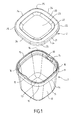
- the container illustrated on the figure 1 comprises a container 1 and a lid 2.
- the container 1 may in particular be used for the preparation of yogurts.
- the container 1 is advantageously made of glass.
- the lid 2 makes it possible to close the container 1.
- the lid 2 is advantageously made of a rigid plastic material, for example made of polypropylene.
- the container 1 has an upper edge 10 extended by an outer annular lateral edge 11.
- the container 1 has a side wall 12 and a bottom 13.
- the outer annular lateral edge 11 belongs to the side wall 12.
- An annular lower edge 14 is arranged outside the container 1 under the outer annular lateral edge 11.
- the cover 2 has a lower support wall 20 surrounded by a lower annular rim 21.
- the lower support wall 20 is provided to rest on the upper edge 10 of the container. More particularly, the cover 2 has stiffening means 22 surrounded by the lower support wall 20.
- the stiffening means 22 are formed by a central concavity 23 of the cover 2 surrounded by the lower support wall 20.
- the container 1 and the lid 2 illustrated in the figures have a square geometry.
- the outer annular lateral edge 11 has several faces 15 interconnected by curved zones 16, and the lower annular edge 21 has several sides 24 connected to each other by rounded edges 25.
- the outer annular lateral edge 11 and the lower annular border 21 have non-circular geometries.
- Other polygonal geometries, for example hexagonal, or non-polygonal, for example elliptical or circular, are however possible for the outer annular lateral edge 11 and / or the lower annular edge 21.
- Retaining members 30 are arranged inside the lower annular edge 21 of the cover 2. According to the invention, at least two retaining members 30 are arranged inside the lower annular edge 21.
- a retaining member 30 is arranged inside each of the sides 24.
- the retaining members 30 are thus arranged outside the portions of the outer annular lateral edge 11 having the smallest radii of curvature.
- the retaining members 30 are regularly spaced within the lower annular edge 21.
- the lid 2 advantageously comprises between two and six retaining members 30 for containers 1 such as individual yogurt pots, a larger number of retaining members 30 may be envisaged for larger containers 1, for example until to twelve retaining members 30 for a container 1 of one to two liters.
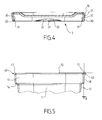
- the retaining members 30 have a chamfered lower face 31, intended to facilitate the placement of the lid 2 on the container 1.
- the retaining members 30 have a chamfered upper face 32, the height of the upper face 32 being greater than the height of the lower face 31, to reconcile a stiffening of the retaining members 30 with a limitation of the height of the retaining members 30 and the bulk of the lid 2.
- the lower annular border 21 is inclined towards the inside of the lid 2 with respect to an outer edge 26 of the lid 2.
- the outer edge 26 is arranged in the upper part of the lower annular edge 21, close to the wall of the lower support 20.
- the outer edge 26 is arranged between the lower bearing wall 20 and the retaining members 30, to allow deformation of the portions of the annular edge lower 21 carrying the retaining members 30.
- the container 1 has retaining thresholds 40 arranged on the side wall 12.
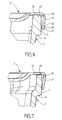
- the retaining thresholds 40 are likely to be crossed by the retaining members 30 when the lid 2 is placed on the container 1, as visible on the figure 6 .
- the outer annular lateral edge 11 extends beyond the retaining thresholds 40 towards the bottom of the container 1.
- the retaining thresholds 40 are connected to the upper edge 10 of the container 1 by rounded surfaces 17.
- the retaining thresholds 40 are extended opposite the upper edge 10 of the container 1 by an inclined wall 18 having a draft angle of less than 5 °, and preferably less than 3 °.
- the inclined wall 18 is formed by the lower part of the outer annular lateral edge 11.
- the outer annular lateral edge 11 extends beyond the retaining thresholds 40 that can be crossed by the retaining members 30 when the cover 2 is put in place on the container 1. Thus, the retaining members 30 bear against each other. the outer annular lateral edge 11 beyond said retaining thresholds 40 when the lid 2 rests on the container 1.
- the container according to the invention is used in the following manner.
- the user places the lid 2 on the container 1.
- the lower faces 31 of the retaining members 30 of the lid 2 bear against the rounded surfaces 17 adjacent to the upper edge 10 of the container 1.
- the pressure exerted by the user on the cover 2 spreads the retaining members 30.
- the lower annular edge 21 being flexibly deformed in bending on the sides 24 of either side of the retaining members 30, the rounded edges 25 forming stiffening elements.
- the retaining thresholds 40 are exceeded by the retaining members 30, the lower bearing wall 20 of the lid 2 bears on the upper edge 10 of the container 1, and the retaining members 30 are moved away from their rest position by the elastic deformation of the lower annular border 21 exert an effort on the outer annular lateral edge 11 of the container 1.
- the lid 2 exerts a slight pressure on the container 1 because of the slope of the inclined wall 18.
- the user can grasp the lid 2 by the outer edge 26 at two opposite sides 24, or at two rounded edges 25.
- the retaining members 30 slide on the outer annular lateral edge 11 until at the retaining thresholds 40 and then release the lid 2 of the container 1 after having exceeded said retaining thresholds 40.
- the proposed construction makes it possible to obtain a resealable container using a container 1 having undemanding dimensional tolerances, such as, for example, a glass container 1.
- a container 1 having undemanding dimensional tolerances such as, for example, a glass container 1.
- the introduction of the lid 2 only requires the gripping of the lid 2 followed by a movement 1 unidirectional to the container 1.
- the removal of the lid 2 requires only the gripping of the container 1 and the lid 2 followed by a unidirectional movement spreading the lid 2 of the container 1.
Landscapes
- Engineering & Computer Science (AREA)
- Mechanical Engineering (AREA)
- Closures For Containers (AREA)
Abstract
Description
- La présente invention concerne le domaine technique des contenants comportant un récipient et un couvercle.
- La présente invention concerne notamment, mais non exclusivement, des contenants réutilisables prévus pour recevoir des préparations alimentaires, telles que par exemple des yaourts.
- Le document
WO 2008 024503 divulgue un contenant de section carrée dans lequel des organes de retenue sont agencés à l'intérieur d'une bordure annulaire inférieure du couvercle, ces organes de retenue étant prévus pour venir en prise sous une bordure latérale annulaire extérieure du récipient lorsque le couvercle ferme le récipient. Ces dispositions permettent d'obtenir une fermeture relativement étanche entre le couvercle et le récipient. Ces dispositions présentent toutefois l'inconvénient d'un retrait peu aisé du couvercle. Pour pallier cet inconvénient, le couvercle comporte une languette de préhension agencée dans un coin. Toutefois, pour permettre le retrait du couvercle en vue de sa réutilisation, la bordure annulaire inférieure du couvercle doit être relativement fine et/ou doit être réalisée dans un matériau souple, pour permettre d'écarter les organes de retenue de la bordure latérale annulaire extérieure du récipient. - Un objet de la présente invention est de proposer un contenant dans lequel le retrait du couvercle est facilité.
- Un objet additionnel de la présente invention est de proposer un contenant qui soit réutilisable.
- Ces objets sont atteints avec un contenant comprenant un récipient et un couvercle, le récipient présentant un bord supérieur prolongé par une bordure latérale annulaire extérieure, le couvercle comportant une paroi d'appui inférieure entourée par une bordure annulaire inférieure, au moins deux organes de retenue étant agencés à l'intérieur de la bordure annulaire inférieure, du fait que la bordure latérale annulaire extérieure s'étend au-delà de seuils de retenue susceptibles d'être franchis par les organes de retenue lorsque le couvercle est mis en place sur le récipient, et en ce que les organes de retenue prennent appui contre la bordure latérale annulaire extérieure au-delà desdits seuils de retenue lorsque le couvercle repose sur le récipient. Ainsi la bordure annulaire inférieure du récipient est déformée par flexion entre deux organes de retenue adjacents, et les organes de retenue exercent une pression latérale sur la bordure latérale annulaire extérieure, au dessous des seuils de retenue. Un simple mouvement axial éloignant le couvercle du récipient peut ainsi permettre d'écarter les organes de retenue par déformation élastique de la bordure annulaire inférieure, pour passer les seuils de retenue. Une déformation de la paroi d'appui inférieure du couvercle n'est pas nécessaire, ce qui permet d'améliorer l'étanchéité d'un contenant réutilisable.
- Avantageusement alors, la bordure annulaire inférieure est inclinée vers l'intérieur du couvercle par rapport à un bord extérieur du couvercle. Cette disposition permet de saisir le couvercle au dessous des organes de retenue sans gêner la déformation de la bordure annulaire inférieure lors du retrait du couvercle. En alternative, l'utilisateur pourrait saisir le couvercle entre les organes de retenue.
- Avantageusement alors, les seuils de retenue sont raccordés au bord supérieur du récipient par des surfaces arrondies. Cette disposition permet d'agencer les seuils de retenue à proximité du bord supérieur du récipient et d'écarter les organes de retenue lors de la mise en place du couvercle sur le récipient.
- Avantageusement encore, les organes de retenue présentent une face inférieure chanfreinée. Cette disposition permet de faciliter la mise en place du couvercle sur le récipient en facilitant le passage des seuils de retenue. Cette disposition permet aussi d'utiliser des seuils de retenue proches du bord supérieur du récipient.
- Avantageusement encore, les seuils de retenue sont prolongés à l'opposé du bord supérieur du récipient par une paroi inclinée présentant un angle de dépouille inférieur à 5°. Cette disposition permet de limiter la déformation élastique de la bordure latérale annulaire extérieure du couvercle lors du passage des seuils de retenue par les organes de retenue. Cette disposition permet aussi de faciliter le retrait du couvercle.
- Avantageusement encore, les organes de retenue sont régulièrement espacés à l'intérieur de la bordure annulaire inférieure. Cette disposition permet d'éviter une indexation précise du couvercle par rapport au récipient.
- Avantageusement encore, le couvercle comporte entre deux et six organes de retenue. Ces dispositions permettent de concilier une retenue suffisante du couvercle avec un retrait aisé du couvercle.
- Avantageusement encore, la bordure latérale annulaire extérieure et la bordure annulaire inférieure présentent des géométries non circulaires. Ces dispositions permettent d'obtenir une variation de la rigidité de la bordure annulaire inférieure du couvercle.
- Avantageusement alors, les organes de retenue sont agencés en dehors des parties de la bordure latérale annulaire extérieure présentant les plus petits rayons de coubure. Ainsi les organes de retenue peuvent être agencés dans les zones les plus déformables de la bordure annulaire inférieure du couvercle.
- Avantageusement alors, la bordure latérale annulaire extérieure présente plusieurs faces raccordées entre elles par des zones incurvées. Cette disposition permet d'accentuer le différentiel de rigidité entre les zones incurvées et lesdites faces, par rapport à une géométrie elliptique, lesdites faces n'étant toutefois pas nécessairement droites.
- Selon une forme de réalisation, la bordure annulaire inférieure présente plusieurs côtés raccordés entre eux par des bords arrondis.
- Avantageusement alors, pour améliorer l'étanchéité entre la paroi d'appui inférieure du couvercle et le bord supérieur du récipient, un organe de retenue est agencé à l'intérieur de chacun des côtés.
- Avantageusement encore, le couvercle présente des moyens de rigidification entourés par la paroi d'appui inférieure. L'augmentation de la rigidité du couvercle permet d'améliorer l'étanchéité entre la paroi d'appui inférieure du couvercle et le bord supérieur du récipient.
- Avantageusement alors, les moyens de rigidification sont formés par une concavité centrale du couvercle. Cette disposition présente l'avantage de faciliter le nettoyage du couvercle et de réduire l'encombrement du contenant.
- Selon un mode de réalisation avantageux, le couvercle est réalisé en matière plastique rigide, plus économique qu'une matière silicone ou élastomère.
- Selon un mode de réalisation avantageux, le récipient est réalisé en verre, ce qui est particulièrement intéressant pour un récipient alimentaire réutilisable.
- L'invention sera mieux comprise à l'étude d'un exemple de réalisation, pris à titre nullement limitatif, illustré dans les figures annexées, dans lesquelles :
- la
figure 1 est une vue en perspective éclatée du couvercle et du récipient d'un contenant selon l'invention, - la
figure 2 est une vue en perspective de dessous du couvercle illustré sur lafigure 1 , - la
figure 3 est une vue de dessous du couvercle illustré sur lesfigures 1 et2 , - la
figure 4 est une vue de côté en coupe transversale du couvercle illustré sur lesfigures 1 à 3 , - la
figure 5 est une vue de côté de la partie supérieure du récipient illustré sur lafigure 1 , - la
figure 6 est une vue partielle en coupe du couvercle illustré sur lesfigures 1 à 4 posé sur le récipient illustré sur lesfigures 1 et5 , au niveau d'un organe de retenue, - la
figure 7 est une vue partielle en coupe du couvercle illustré sur lesfigures 1 à 4 posé sur le récipient illustré sur lesfigures 1 et5 , entre deux organes de retenue. - Le contenant illustré sur la
figure 1 comprend un récipient 1 et un couvercle 2. Le récipient 1 peut notamment être utilisé pour la préparation de yaourts. A cet effet, le récipient 1 est avantageusement réalisé en verre. Le couvercle 2 permet de fermer le récipient 1. Le couvercle 2 est avantageusement réalisé en matière plastique rigide, par exemple en polypropylène. - Le récipient 1 présente un bord supérieur 10 prolongé par une bordure latérale annulaire extérieure 11. Le récipient 1 comporte une paroi latérale 12 et un fond 13. La bordure latérale annulaire extérieure 11 appartient à la paroi latérale 12. Un rebord inférieur annulaire 14 est agencé à l'extérieur du récipient 1 sous la bordure latérale annulaire extérieure 11.
- Le couvercle 2 comporte une paroi d'appui inférieure 20 entourée par une bordure annulaire inférieure 21. La paroi d'appui inférieure 20 est prévue pour reposer sur le bord supérieur 10 du récipient. Plus particulièrement, le couvercle 2 présente des moyens de rigidification 22 entourés par la paroi d'appui inférieure 20. Dans l'exemple de réalisation illustré sur la
figure 1 , les moyens de rigidification 22 sont formés par une concavité centrale 23 du couvercle 2 entourée par la paroi d'appui inférieure 20. - Le récipient 1 et le couvercle 2 illustrés sur les figures présentent une géométrie carrée. La bordure latérale annulaire extérieure 11 présente plusieurs faces 15 raccordées entre elles par des zones incurvées 16, et la bordure annulaire inférieure 21 présente plusieurs côtés 24 raccordés entre eux par des bords arrondis 25. Ainsi la bordure latérale annulaire extérieure 11 et la bordure annulaire inférieure 21 présentent des géométries non circulaires. D'autres géométries polygonales, par exemple hexagonale, ou non polygonales, par exemple elliptique ou circulaire, sont toutefois envisageables pour la bordure latérale annulaire extérieure 11 et/ou la bordure annulaire inférieure 21.
- Des organes de retenue 30 sont agencés à l'intérieur de la bordure annulaire inférieure 21 du couvercle 2. Selon l'invention, au moins deux organes de retenue 30 sont agencés à l'intérieur de la bordure annulaire inférieure 21.
- Tel que visible sur les
figures 2 et 3 , un organe de retenue 30 est agencé à l'intérieur de chacune des côtés 24. Les organes de retenue 30 sont ainsi agencés en dehors des parties de la bordure latérale annulaire extérieure 11 présentant les plus petits rayons de coubure. Les organes de retenue 30 sont régulièrement espacés à l'intérieur de la bordure annulaire inférieure 21. - Le couvercle 2 comporte avantageusement entre deux et six organes de retenue 30 pour des récipients 1 tels que des pots de yaourts individuels, un nombre supérieur d'organes de retenue 30 peut être envisagé pour des récipients 1 de plus grande taille, par exemple jusqu'à douze d'organes de retenue 30 pour un récipient 1 de un à deux litres.
- Tel que visible sur la
figure 4 , les organes de retenue 30 présentent une face inférieure 31 chanfreinée, prévue pour faciliter la mise en place du couvercle 2 sur le récipient 1. Les organes de retenue 30 présentent une face supérieure 32 chanfreinée, la hauteur de la face supérieure 32 étant supérieure à la hauteur de la face inférieure 31, pour concilier une rigidification des organes de retenue 30 avec une limitation de la hauteur des organes de retenue 30 et de l'encombrement du couvercle 2. - Tel que visible sur la
figure 4 , la bordure annulaire inférieure 21 est inclinée vers l'intérieur du couvercle 2 par rapport à un bord extérieur 26 du couvercle 2. Le bord extérieur 26 est agencé dans la partie supérieure de la bordure annulaire inférieure 21, à proximité de la paroi d'appui inférieure 20. Le bord extérieur 26 est agencé entre la paroi d'appui inférieure 20 et les organes de retenue 30, pour permettre la déformation des parties de la bordure annulaire inférieure 21 portant les organes de retenue 30. - Tel que visible sur la
figure 5 , le récipient 1 présente des seuils de retenue 40 agencés sur la paroi latérale 12. Les seuils de retenue 40 sont susceptibles d'être franchis par les organes de retenue 30 lorsque le couvercle 2 est mis en place sur le récipient 1, tel que visible sur lafigure 6 . La bordure latérale annulaire extérieure 11 s'étend au-delà des seuils de retenue 40 en direction du fond du récipient 1. Les seuils de retenue 40 sont raccordés au bord supérieur 10 du récipient 1 par des surfaces arrondies 17. Les seuils de retenue 40 sont prolongés à l'opposé du bord supérieur 10 du récipient 1 par une paroi inclinée 18 présentant un angle de dépouille A inférieur à 5°, et de préférence inférieur à 3°. La paroi inclinée 18 est formée par la partie inférieure de la bordure latérale annulaire extérieure 11. - La bordure latérale annulaire extérieure 11 s'étend au-delà des seuils de retenue 40 susceptibles d'être franchis par les organes de retenue 30 lorsque le couvercle 2 est mis en place sur le récipient 1. Ainsi les organes de retenue 30 prennent appui contre la bordure latérale annulaire extérieure 11 au-delà desdits seuils de retenue 40 lorsque le couvercle 2 repose sur le récipient 1.
- Le contenant selon l'invention s'utilise de la manière suivante.
- Pour fermer le contenant, l'utilisateur pose le couvercle 2 sur le récipient 1. Les faces inférieures 31 des organes de retenue 30 du couvercle 2 viennent en appui sur les surfaces arrondies 17 adjacentes au bord supérieur 10 du récipient 1. La pression exercée par l'utilisateur sur le couvercle 2 écarte les organes de retenue 30. La bordure annulaire inférieure 21 étant déformée élastiquement en flexion sur les côtés 24 de de part et d'autre des organes de retenue 30, les bords arrondis 25 formant des éléments rigificateurs. Lorsque les seuils de retenue 40 sont dépassés par les organes de retenue 30, la paroi d'appui inférieure 20 du couvercle 2 vient en appui sur le bord supérieur 10 du récipient 1, et les organes de retenue 30 éloignés de leur position de repos par la déformation élastique de la bordure annulaire inférieure 21 exercent un effort de rappel sur la bordure latérale annulaire extérieure 11 du récipient 1. Le couvercle 2 exerce une légère pression sur le récipient 1 du fait de la pente de la paroi inclinée 18.
- Pour ouvrir le contenant, l'utilisateur peut saisir le couvercle 2 par le bord extérieur 26 au niveau de deux côtés 24 opposés, ou au niveau de deux bords arrondis 25. Les organes de retenue 30 glissent sur la bordure latérale annulaire extérieure 11 jusqu'aux seuils de retenue 40 puis libèrent le couvercle 2 du récipient 1 après avoir dépassé lesdits seuils de retenue 40.
- La construction proposée permet d'obtenir un contenant refermable utilisant un récipient 1 présentant des tolérances dimensionnelles peu exigeantes, tel que par exemple un récipient en verre 1. La mise en place du couvercle 2 nécessite seulement la préhension du couvercle 2 suivie d'un mouvement unidirectionnel vers le récipient 1. Le retrait du couvercle 2 nécessite seulement la préhension du récipient 1 et du couvercle 2 suivie d'un mouvement unidirectionnel écartant le couvercle 2 du récipient 1.
- La présente invention n'est nullement limitée à l'exemple de réalisation décrit et à ses variantes, mais englobe de nombreuses modifications dans le cadre des revendications.
Claims (16)
- Contenant comprenant un récipient (1) et un couvercle (2), le récipient (1) présentant un bord supérieur (10) prolongé par une bordure latérale annulaire extérieure (11), le couvercle (2) comportant une paroi d'appui inférieure (20) entourée par une bordure annulaire inférieure (21), au moins deux organes de retenue (30) étant agencés à l'intérieur de la bordure annulaire inférieure (21), caractérisé en ce que la bordure latérale annulaire extérieure (11) s'étend au-delà de seuils de retenue (40) susceptibles d'être franchis par les organes de retenue (30) lorsque le couvercle (2) est mis en place sur le récipient (1), et en ce que les organes de retenue (30) prennent appui contre la bordure latérale annulaire extérieure (11) au-delà desdits seuils de retenue (40) lorsque le couvercle (2) repose sur le récipient (1).
- Contenant selon la revendication 1, caractérisé en ce que la bordure annulaire inférieure (21) est inclinée vers l'intérieur du couvercle (2) par rapport à un bord extérieur (26) du couvercle (2).
- Contenant selon l'une des revendications 1 ou 2, caractérisé en ce que les seuils de retenue (40) sont raccordés au bord supérieur du récipient (1) par des surfaces arrondies (17).
- Contenant selon l'une des revendications 1 à 3, caractérisé en ce que les organes de retenue (30) présentent une face inférieure chanfreinée (31).
- Contenant selon l'une des revendications 1 à 4, caractérisé en ce que les seuils de retenue (40) sont prolongés à l'opposé du bord supérieur (10) du récipient (1) par une paroi inclinée (18) présentant un angle de dépouille inférieur à 5°.
- Contenant selon l'une des revendications 1 à 5, caractérisé en ce que les organes de retenue (30) sont régulièrement espacés à l'intérieur de la bordure annulaire inférieure (21).
- Contenant selon l'une des revendications 1 à 6, caractérisé en ce que le couvercle (2) comporte entre deux et six organes de retenue (30).
- Contenant selon l'une des revendications 1 à 7, caractérisé en ce que la bordure latérale annulaire extérieure (11) et la bordure annulaire inférieure (21) présentent des géométries non circulaires.
- Contenant selon la revendication 8, caractérisé en ce que les organes de retenue (30) sont agencés en dehors des parties de la bordure latérale annulaire extérieure (11) présentant les plus petits rayons de coubure.
- Contenant selon la revendication 9, caractérisé en ce que la bordure latérale annulaire extérieure (11) présente plusieurs faces (15) raccordées entre elles par des zones incurvées (16).
- Contenant selon l'une des revendications 8 à 10, caractérisé en ce que la bordure annulaire inférieure (21) présente plusieurs côtés (24) raccordés entre eux par des bords arrondis (25).
- Contenant selon la revendication 11, caractérisé en ce qu'un organe de retenue (30) est agencé à l'intérieur de chacun des côtés (24).
- Contenant selon l'une des revendications 1 à 12, caractérisé que le couvercle (2) présente des moyens de rigidification (22) entourés par la paroi d'appui inférieure (20).
- Contenant selon la revendication 13, caractérisé en ce que les moyens de rigidification (22) sont formés par une concavité centrale (23) du couvercle (2).
- Contenant selon l'une des revendications 1 à 14, caractérisé que le couvercle (2) est réalisé en matière plastique rigide.
- Contenant selon l'une des revendications 1 à 15, caractérisé que le récipient (1) est réalisé en verre.
Applications Claiming Priority (1)
| Application Number | Priority Date | Filing Date | Title |
|---|---|---|---|
| FR1053846A FR2960220B1 (fr) | 2010-05-18 | 2010-05-18 | Contenant comprenant un recipient et un couvercle |
Publications (2)
| Publication Number | Publication Date |
|---|---|
| EP2388205A1 true EP2388205A1 (fr) | 2011-11-23 |
| EP2388205B1 EP2388205B1 (fr) | 2020-04-08 |
Family
ID=43048904
Family Applications (1)
| Application Number | Title | Priority Date | Filing Date |
|---|---|---|---|
| EP11305606.3A Active EP2388205B1 (fr) | 2010-05-18 | 2011-05-18 | Contenant comprenant un récipient et un couvercle |
Country Status (5)
| Country | Link |
|---|---|
| EP (1) | EP2388205B1 (fr) |
| CN (2) | CN102295098B (fr) |
| ES (1) | ES2787510T3 (fr) |
| FR (1) | FR2960220B1 (fr) |
| WO (1) | WO2011144869A1 (fr) |
Families Citing this family (3)
| Publication number | Priority date | Publication date | Assignee | Title |
|---|---|---|---|---|
| FR2960220B1 (fr) * | 2010-05-18 | 2013-10-25 | Seb Sa | Contenant comprenant un recipient et un couvercle |
| TWI722918B (zh) * | 2020-06-09 | 2021-03-21 | 林春成 | 可防止液體外濺的杯蓋 |
| FR3116265B1 (fr) | 2020-11-18 | 2023-04-14 | Seb Sa | Couvercle etanche pour recipient, et contenant comprenant un recipient et un couvercle etanche |
Citations (7)
| Publication number | Priority date | Publication date | Assignee | Title |
|---|---|---|---|---|
| BE494244A (fr) * | ||||
| US1802739A (en) * | 1927-12-21 | 1931-04-28 | Anchor Cap & Closure Corp | Friction closure cap |
| US1858826A (en) * | 1927-03-18 | 1932-05-17 | Anchor Cap & Closure Corp | Friction closure cap |
| FR1274143A (fr) * | 1960-11-21 | 1961-10-20 | Plastomatic Corp | Récipients en matière plastique, procédé et appareil pour le remplissage et le cachetage de tels récipients |
| FR2457814A1 (fr) * | 1979-05-28 | 1980-12-26 | Barmont Francois | Couvercle en matiere plastique, notamment pour des recipients en verre |
| WO2001030662A1 (fr) * | 1999-10-27 | 2001-05-03 | Legue Gerardus | Accessoire permettant de boire adapte a un haut d'une canette de biere ou d'une autre boisson |
| WO2008024503A2 (fr) | 2006-08-25 | 2008-02-28 | Wells' Dairy Inc. | Récipient amélioré |
Family Cites Families (2)
| Publication number | Priority date | Publication date | Assignee | Title |
|---|---|---|---|---|
| CN1077537C (zh) * | 1999-11-04 | 2002-01-09 | 上海市青浦县华新包装厂 | 开口钢提桶紧耳盖 |
| FR2960220B1 (fr) * | 2010-05-18 | 2013-10-25 | Seb Sa | Contenant comprenant un recipient et un couvercle |
-
2010
- 2010-05-18 FR FR1053846A patent/FR2960220B1/fr not_active Expired - Fee Related
-
2011
- 2011-05-18 ES ES11305606T patent/ES2787510T3/es active Active
- 2011-05-18 CN CN201110128472.1A patent/CN102295098B/zh active Active
- 2011-05-18 CN CN2011201582726U patent/CN202175282U/zh not_active Expired - Fee Related
- 2011-05-18 EP EP11305606.3A patent/EP2388205B1/fr active Active
- 2011-05-18 WO PCT/FR2011/051126 patent/WO2011144869A1/fr not_active Ceased
Patent Citations (7)
| Publication number | Priority date | Publication date | Assignee | Title |
|---|---|---|---|---|
| BE494244A (fr) * | ||||
| US1858826A (en) * | 1927-03-18 | 1932-05-17 | Anchor Cap & Closure Corp | Friction closure cap |
| US1802739A (en) * | 1927-12-21 | 1931-04-28 | Anchor Cap & Closure Corp | Friction closure cap |
| FR1274143A (fr) * | 1960-11-21 | 1961-10-20 | Plastomatic Corp | Récipients en matière plastique, procédé et appareil pour le remplissage et le cachetage de tels récipients |
| FR2457814A1 (fr) * | 1979-05-28 | 1980-12-26 | Barmont Francois | Couvercle en matiere plastique, notamment pour des recipients en verre |
| WO2001030662A1 (fr) * | 1999-10-27 | 2001-05-03 | Legue Gerardus | Accessoire permettant de boire adapte a un haut d'une canette de biere ou d'une autre boisson |
| WO2008024503A2 (fr) | 2006-08-25 | 2008-02-28 | Wells' Dairy Inc. | Récipient amélioré |
Also Published As
| Publication number | Publication date |
|---|---|
| CN102295098B (zh) | 2016-01-13 |
| CN202175282U (zh) | 2012-03-28 |
| FR2960220A1 (fr) | 2011-11-25 |
| FR2960220B1 (fr) | 2013-10-25 |
| CN102295098A (zh) | 2011-12-28 |
| ES2787510T3 (es) | 2020-10-16 |
| EP2388205B1 (fr) | 2020-04-08 |
| WO2011144869A1 (fr) | 2011-11-24 |
Similar Documents
| Publication | Publication Date | Title |
|---|---|---|
| EP2464580B1 (fr) | Coiffe de verrouillage pour recipient a col avec une capsule a pattes de fixation | |
| EP2585576B1 (fr) | Boite de petri comportant des moyens de verrouillage en vue de la constitution d'une pile | |
| USD649448S1 (en) | Polygonal food container | |
| EP1512637B1 (fr) | Couvercle de fermeture de pots alimentaires | |
| FR2545713A1 (fr) | Dispositif reglable pour le transport de recipients | |
| USD610350S1 (en) | Memorabilia container | |
| FR2671059A1 (fr) | Receptacle a couvercle circulaire rotatif pour poubelle. | |
| EP2388205B1 (fr) | Contenant comprenant un récipient et un couvercle | |
| EP2735524A1 (fr) | Contenant comprenant un recipient et un couvercle | |
| CA2929748A1 (fr) | Conteneur a palette empilable muni d'une armature superieure de renfort | |
| FR2478986A3 (fr) | Gobelet en matiere plastique mince | |
| EP0926080B1 (fr) | Récipient muni d'un dispositif d'extraction automatique d'une paille | |
| EP1150022A2 (fr) | Système et procédé d'assemblage, et dispositifs pourvus de ce système | |
| US20080041858A1 (en) | Canister with a sealed lid | |
| EP2387877B1 (fr) | Dispositif d'égouttage d'une faisselle dans un récipient | |
| EP1022232B1 (fr) | Conditionnement pour produits présentés en emballages groupés | |
| FR2921906A1 (fr) | Recipient a element d'obturation amovible | |
| EP4247725B1 (fr) | Couvercle etanche pour recipient, et contenant comprenant un recipient et un couvercle etanche | |
| FR2962634A1 (fr) | Element de cuisson pour cuiseur vapeur | |
| EP0934888B1 (fr) | Dispositif de conditionnement de pots d'emballage de fromage blanc | |
| FR2983459A1 (fr) | Dispositif de maintien de pots contenant un produit alimentaire d'un appareil de refrigeration | |
| FR2669899A1 (fr) | Plateau intercalaire pour le conditionnement de bouteilles. | |
| FR3082834A1 (fr) | Couvercle deformable, procede de fabrication et ensemble comprenant un recipient et un couvercle deformable | |
| FR2810520A1 (fr) | Dispositif de rehausse pour presentation de produits commercialises | |
| FR3054959A1 (fr) | Couvercle pour recipient de stockage d'un produit, notamment d'un produit cosmetique |
Legal Events
| Date | Code | Title | Description |
|---|---|---|---|
| AK | Designated contracting states |
Kind code of ref document: A1 Designated state(s): AL AT BE BG CH CY CZ DE DK EE ES FI FR GB GR HR HU IE IS IT LI LT LU LV MC MK MT NL NO PL PT RO RS SE SI SK SM TR |
|
| AX | Request for extension of the european patent |
Extension state: BA ME |
|
| PUAI | Public reference made under article 153(3) epc to a published international application that has entered the european phase |
Free format text: ORIGINAL CODE: 0009012 |
|
| 17P | Request for examination filed |
Effective date: 20120523 |
|
| RAP1 | Party data changed (applicant data changed or rights of an application transferred) |
Owner name: SEB S.A. |
|
| STAA | Information on the status of an ep patent application or granted ep patent |
Free format text: STATUS: EXAMINATION IS IN PROGRESS |
|
| 17Q | First examination report despatched |
Effective date: 20171009 |
|
| GRAP | Despatch of communication of intention to grant a patent |
Free format text: ORIGINAL CODE: EPIDOSNIGR1 |
|
| STAA | Information on the status of an ep patent application or granted ep patent |
Free format text: STATUS: GRANT OF PATENT IS INTENDED |
|
| INTG | Intention to grant announced |
Effective date: 20191106 |
|
| GRAS | Grant fee paid |
Free format text: ORIGINAL CODE: EPIDOSNIGR3 |
|
| GRAA | (expected) grant |
Free format text: ORIGINAL CODE: 0009210 |
|
| STAA | Information on the status of an ep patent application or granted ep patent |
Free format text: STATUS: THE PATENT HAS BEEN GRANTED |
|
| AK | Designated contracting states |
Kind code of ref document: B1 Designated state(s): AL AT BE BG CH CY CZ DE DK EE ES FI FR GB GR HR HU IE IS IT LI LT LU LV MC MK MT NL NO PL PT RO RS SE SI SK SM TR |
|
| REG | Reference to a national code |
Ref country code: GB Ref legal event code: FG4D Free format text: NOT ENGLISH |
|
| REG | Reference to a national code |
Ref country code: CH Ref legal event code: EP Ref country code: AT Ref legal event code: REF Ref document number: 1254088 Country of ref document: AT Kind code of ref document: T Effective date: 20200415 |
|
| REG | Reference to a national code |
Ref country code: DE Ref legal event code: R096 Ref document number: 602011066101 Country of ref document: DE |
|
| REG | Reference to a national code |
Ref country code: IE Ref legal event code: FG4D Free format text: LANGUAGE OF EP DOCUMENT: FRENCH |
|
| REG | Reference to a national code |
Ref country code: NL Ref legal event code: MP Effective date: 20200408 |
|
| REG | Reference to a national code |
Ref country code: LT Ref legal event code: MG4D |
|
| REG | Reference to a national code |
Ref country code: ES Ref legal event code: FG2A Ref document number: 2787510 Country of ref document: ES Kind code of ref document: T3 Effective date: 20201016 |
|
| PG25 | Lapsed in a contracting state [announced via postgrant information from national office to epo] |
Ref country code: IS Free format text: LAPSE BECAUSE OF FAILURE TO SUBMIT A TRANSLATION OF THE DESCRIPTION OR TO PAY THE FEE WITHIN THE PRESCRIBED TIME-LIMIT Effective date: 20200808 Ref country code: SE Free format text: LAPSE BECAUSE OF FAILURE TO SUBMIT A TRANSLATION OF THE DESCRIPTION OR TO PAY THE FEE WITHIN THE PRESCRIBED TIME-LIMIT Effective date: 20200408 Ref country code: FI Free format text: LAPSE BECAUSE OF FAILURE TO SUBMIT A TRANSLATION OF THE DESCRIPTION OR TO PAY THE FEE WITHIN THE PRESCRIBED TIME-LIMIT Effective date: 20200408 Ref country code: GR Free format text: LAPSE BECAUSE OF FAILURE TO SUBMIT A TRANSLATION OF THE DESCRIPTION OR TO PAY THE FEE WITHIN THE PRESCRIBED TIME-LIMIT Effective date: 20200709 Ref country code: NO Free format text: LAPSE BECAUSE OF FAILURE TO SUBMIT A TRANSLATION OF THE DESCRIPTION OR TO PAY THE FEE WITHIN THE PRESCRIBED TIME-LIMIT Effective date: 20200708 Ref country code: PT Free format text: LAPSE BECAUSE OF FAILURE TO SUBMIT A TRANSLATION OF THE DESCRIPTION OR TO PAY THE FEE WITHIN THE PRESCRIBED TIME-LIMIT Effective date: 20200817 Ref country code: NL Free format text: LAPSE BECAUSE OF FAILURE TO SUBMIT A TRANSLATION OF THE DESCRIPTION OR TO PAY THE FEE WITHIN THE PRESCRIBED TIME-LIMIT Effective date: 20200408 Ref country code: LT Free format text: LAPSE BECAUSE OF FAILURE TO SUBMIT A TRANSLATION OF THE DESCRIPTION OR TO PAY THE FEE WITHIN THE PRESCRIBED TIME-LIMIT Effective date: 20200408 |
|
| REG | Reference to a national code |
Ref country code: AT Ref legal event code: MK05 Ref document number: 1254088 Country of ref document: AT Kind code of ref document: T Effective date: 20200408 |
|
| PG25 | Lapsed in a contracting state [announced via postgrant information from national office to epo] |
Ref country code: LV Free format text: LAPSE BECAUSE OF FAILURE TO SUBMIT A TRANSLATION OF THE DESCRIPTION OR TO PAY THE FEE WITHIN THE PRESCRIBED TIME-LIMIT Effective date: 20200408 Ref country code: BG Free format text: LAPSE BECAUSE OF FAILURE TO SUBMIT A TRANSLATION OF THE DESCRIPTION OR TO PAY THE FEE WITHIN THE PRESCRIBED TIME-LIMIT Effective date: 20200708 Ref country code: RS Free format text: LAPSE BECAUSE OF FAILURE TO SUBMIT A TRANSLATION OF THE DESCRIPTION OR TO PAY THE FEE WITHIN THE PRESCRIBED TIME-LIMIT Effective date: 20200408 Ref country code: HR Free format text: LAPSE BECAUSE OF FAILURE TO SUBMIT A TRANSLATION OF THE DESCRIPTION OR TO PAY THE FEE WITHIN THE PRESCRIBED TIME-LIMIT Effective date: 20200408 |
|
| REG | Reference to a national code |
Ref country code: DE Ref legal event code: R119 Ref document number: 602011066101 Country of ref document: DE |
|
| PG25 | Lapsed in a contracting state [announced via postgrant information from national office to epo] |
Ref country code: AL Free format text: LAPSE BECAUSE OF FAILURE TO SUBMIT A TRANSLATION OF THE DESCRIPTION OR TO PAY THE FEE WITHIN THE PRESCRIBED TIME-LIMIT Effective date: 20200408 |
|
| PG25 | Lapsed in a contracting state [announced via postgrant information from national office to epo] |
Ref country code: SM Free format text: LAPSE BECAUSE OF FAILURE TO SUBMIT A TRANSLATION OF THE DESCRIPTION OR TO PAY THE FEE WITHIN THE PRESCRIBED TIME-LIMIT Effective date: 20200408 Ref country code: LI Free format text: LAPSE BECAUSE OF NON-PAYMENT OF DUE FEES Effective date: 20200531 Ref country code: EE Free format text: LAPSE BECAUSE OF FAILURE TO SUBMIT A TRANSLATION OF THE DESCRIPTION OR TO PAY THE FEE WITHIN THE PRESCRIBED TIME-LIMIT Effective date: 20200408 Ref country code: DK Free format text: LAPSE BECAUSE OF FAILURE TO SUBMIT A TRANSLATION OF THE DESCRIPTION OR TO PAY THE FEE WITHIN THE PRESCRIBED TIME-LIMIT Effective date: 20200408 Ref country code: AT Free format text: LAPSE BECAUSE OF FAILURE TO SUBMIT A TRANSLATION OF THE DESCRIPTION OR TO PAY THE FEE WITHIN THE PRESCRIBED TIME-LIMIT Effective date: 20200408 Ref country code: IT Free format text: LAPSE BECAUSE OF FAILURE TO SUBMIT A TRANSLATION OF THE DESCRIPTION OR TO PAY THE FEE WITHIN THE PRESCRIBED TIME-LIMIT Effective date: 20200408 Ref country code: MC Free format text: LAPSE BECAUSE OF FAILURE TO SUBMIT A TRANSLATION OF THE DESCRIPTION OR TO PAY THE FEE WITHIN THE PRESCRIBED TIME-LIMIT Effective date: 20200408 Ref country code: CH Free format text: LAPSE BECAUSE OF NON-PAYMENT OF DUE FEES Effective date: 20200531 Ref country code: CZ Free format text: LAPSE BECAUSE OF FAILURE TO SUBMIT A TRANSLATION OF THE DESCRIPTION OR TO PAY THE FEE WITHIN THE PRESCRIBED TIME-LIMIT Effective date: 20200408 Ref country code: RO Free format text: LAPSE BECAUSE OF FAILURE TO SUBMIT A TRANSLATION OF THE DESCRIPTION OR TO PAY THE FEE WITHIN THE PRESCRIBED TIME-LIMIT Effective date: 20200408 |
|
| PLBE | No opposition filed within time limit |
Free format text: ORIGINAL CODE: 0009261 |
|
| STAA | Information on the status of an ep patent application or granted ep patent |
Free format text: STATUS: NO OPPOSITION FILED WITHIN TIME LIMIT |
|
| PG25 | Lapsed in a contracting state [announced via postgrant information from national office to epo] |
Ref country code: SK Free format text: LAPSE BECAUSE OF FAILURE TO SUBMIT A TRANSLATION OF THE DESCRIPTION OR TO PAY THE FEE WITHIN THE PRESCRIBED TIME-LIMIT Effective date: 20200408 Ref country code: PL Free format text: LAPSE BECAUSE OF FAILURE TO SUBMIT A TRANSLATION OF THE DESCRIPTION OR TO PAY THE FEE WITHIN THE PRESCRIBED TIME-LIMIT Effective date: 20200408 |
|
| 26N | No opposition filed |
Effective date: 20210112 |
|
| GBPC | Gb: european patent ceased through non-payment of renewal fee |
Effective date: 20200708 |
|
| PG25 | Lapsed in a contracting state [announced via postgrant information from national office to epo] |
Ref country code: LU Free format text: LAPSE BECAUSE OF NON-PAYMENT OF DUE FEES Effective date: 20200518 |
|
| PG25 | Lapsed in a contracting state [announced via postgrant information from national office to epo] |
Ref country code: IE Free format text: LAPSE BECAUSE OF NON-PAYMENT OF DUE FEES Effective date: 20200518 Ref country code: GB Free format text: LAPSE BECAUSE OF NON-PAYMENT OF DUE FEES Effective date: 20200708 |
|
| PG25 | Lapsed in a contracting state [announced via postgrant information from national office to epo] |
Ref country code: DE Free format text: LAPSE BECAUSE OF NON-PAYMENT OF DUE FEES Effective date: 20201201 Ref country code: SI Free format text: LAPSE BECAUSE OF FAILURE TO SUBMIT A TRANSLATION OF THE DESCRIPTION OR TO PAY THE FEE WITHIN THE PRESCRIBED TIME-LIMIT Effective date: 20200408 |
|
| PG25 | Lapsed in a contracting state [announced via postgrant information from national office to epo] |
Ref country code: TR Free format text: LAPSE BECAUSE OF FAILURE TO SUBMIT A TRANSLATION OF THE DESCRIPTION OR TO PAY THE FEE WITHIN THE PRESCRIBED TIME-LIMIT Effective date: 20200408 Ref country code: MT Free format text: LAPSE BECAUSE OF FAILURE TO SUBMIT A TRANSLATION OF THE DESCRIPTION OR TO PAY THE FEE WITHIN THE PRESCRIBED TIME-LIMIT Effective date: 20200408 Ref country code: CY Free format text: LAPSE BECAUSE OF FAILURE TO SUBMIT A TRANSLATION OF THE DESCRIPTION OR TO PAY THE FEE WITHIN THE PRESCRIBED TIME-LIMIT Effective date: 20200408 |
|
| PG25 | Lapsed in a contracting state [announced via postgrant information from national office to epo] |
Ref country code: MK Free format text: LAPSE BECAUSE OF FAILURE TO SUBMIT A TRANSLATION OF THE DESCRIPTION OR TO PAY THE FEE WITHIN THE PRESCRIBED TIME-LIMIT Effective date: 20200408 |
|
| PGFP | Annual fee paid to national office [announced via postgrant information from national office to epo] |
Ref country code: ES Payment date: 20250610 Year of fee payment: 15 |
|
| PGFP | Annual fee paid to national office [announced via postgrant information from national office to epo] |
Ref country code: BE Payment date: 20250527 Year of fee payment: 15 |
|
| PGFP | Annual fee paid to national office [announced via postgrant information from national office to epo] |
Ref country code: FR Payment date: 20250530 Year of fee payment: 15 |