EP2388106B1 - Abtragvorrichtung - Google Patents
Abtragvorrichtung Download PDFInfo
- Publication number
- EP2388106B1 EP2388106B1 EP10163543A EP10163543A EP2388106B1 EP 2388106 B1 EP2388106 B1 EP 2388106B1 EP 10163543 A EP10163543 A EP 10163543A EP 10163543 A EP10163543 A EP 10163543A EP 2388106 B1 EP2388106 B1 EP 2388106B1
- Authority
- EP
- European Patent Office
- Prior art keywords
- abutment
- reference plane
- tool
- edge
- lens
- Prior art date
- Legal status (The legal status is an assumption and is not a legal conclusion. Google has not performed a legal analysis and makes no representation as to the accuracy of the status listed.)
- Not-in-force
Links
- 238000003801 milling Methods 0.000 claims 1
- 238000005304 joining Methods 0.000 description 100
- 239000011521 glass Substances 0.000 description 59
- 230000002123 temporal effect Effects 0.000 description 22
- 239000000463 material Substances 0.000 description 13
- 239000011248 coating agent Substances 0.000 description 11
- 238000000576 coating method Methods 0.000 description 11
- 230000015572 biosynthetic process Effects 0.000 description 8
- 210000000887 face Anatomy 0.000 description 6
- 238000000227 grinding Methods 0.000 description 6
- 238000004519 manufacturing process Methods 0.000 description 5
- 238000000034 method Methods 0.000 description 4
- 239000008186 active pharmaceutical agent Substances 0.000 description 3
- 239000000853 adhesive Substances 0.000 description 3
- 230000001070 adhesive effect Effects 0.000 description 3
- 238000003754 machining Methods 0.000 description 3
- 230000013011 mating Effects 0.000 description 3
- 230000000295 complement effect Effects 0.000 description 2
- 238000005520 cutting process Methods 0.000 description 2
- 239000006228 supernatant Substances 0.000 description 2
- 239000006061 abrasive grain Substances 0.000 description 1
- 230000001419 dependent effect Effects 0.000 description 1
- 210000001061 forehead Anatomy 0.000 description 1
- 210000003128 head Anatomy 0.000 description 1
- 238000001746 injection moulding Methods 0.000 description 1
- 238000002360 preparation method Methods 0.000 description 1
- 239000005871 repellent Substances 0.000 description 1
- 239000007787 solid Substances 0.000 description 1
- 238000010408 sweeping Methods 0.000 description 1
Images

Classifications
-
- B—PERFORMING OPERATIONS; TRANSPORTING
- B24—GRINDING; POLISHING
- B24B—MACHINES, DEVICES, OR PROCESSES FOR GRINDING OR POLISHING; DRESSING OR CONDITIONING OF ABRADING SURFACES; FEEDING OF GRINDING, POLISHING, OR LAPPING AGENTS
- B24B41/00—Component parts such as frames, beds, carriages, headstocks
- B24B41/06—Work supports, e.g. adjustable steadies
-
- B—PERFORMING OPERATIONS; TRANSPORTING
- B24—GRINDING; POLISHING
- B24B—MACHINES, DEVICES, OR PROCESSES FOR GRINDING OR POLISHING; DRESSING OR CONDITIONING OF ABRADING SURFACES; FEEDING OF GRINDING, POLISHING, OR LAPPING AGENTS
- B24B9/00—Machines or devices designed for grinding edges or bevels on work or for removing burrs; Accessories therefor
- B24B9/02—Machines or devices designed for grinding edges or bevels on work or for removing burrs; Accessories therefor characterised by a special design with respect to properties of materials specific to articles to be ground
- B24B9/06—Machines or devices designed for grinding edges or bevels on work or for removing burrs; Accessories therefor characterised by a special design with respect to properties of materials specific to articles to be ground of non-metallic inorganic material, e.g. stone, ceramics, porcelain
- B24B9/08—Machines or devices designed for grinding edges or bevels on work or for removing burrs; Accessories therefor characterised by a special design with respect to properties of materials specific to articles to be ground of non-metallic inorganic material, e.g. stone, ceramics, porcelain of glass
- B24B9/14—Machines or devices designed for grinding edges or bevels on work or for removing burrs; Accessories therefor characterised by a special design with respect to properties of materials specific to articles to be ground of non-metallic inorganic material, e.g. stone, ceramics, porcelain of glass of optical work, e.g. lenses, prisms
- B24B9/146—Accessories, e.g. lens mounting devices
Definitions
- the invention relates to a device for processing a spectacle lens of rimless spectacles, wherein the machining involves the removal of material on the front side of the spectacle lens in the region of joining surfaces to be formed.
- a method for producing a rimless glasses is known, are glued in the connecting elements of the jaws and the bridge of the glasses with the front sides of the lenses.
- first two glasses raw glasses are made of a plastic, on the front and back of a coating is applied.
- the two coated glasses raw glasses are ground in such a way that two lenses are obtained with a desired disc shape.
- the coating is removed to form joining surfaces, which correspond in shape and dimensions substantially at the connecting elements formed joining surfaces.
- the fasteners are then bonded to the front of the lenses at the mounting locations. Since the base material is exposed to the spectacle lenses in the area of the joining surfaces, a permanently fixed adhesive bond can be produced between the connecting elements and the spectacle lenses.
- the known device comprises a mounting plate as well as a holding device for each spectacle lens of the spectacles to be produced, with the aid of which the spectacle lens is fixed to the mounting plate such that its front side faces away from the mounting plate and is exposed.
- a grinding device comprises a drive unit and a tool carried by the drive unit, which is designed as a face grinder.
- the grinding apparatus may be driven under control of a program control device over the location where a single joint surface is to be formed, is lowered there until the end face of the low contact forehead grinder is in contact with the spectacle lens, and then locally abrades the coating thereby forming a joining surface on the spectacle lens. It has proven to be difficult, by means of the known device, to form the joint surfaces exactly at the locations predefined for them on the front side of the spectacle lens.
- the invention has for its object to provide a device for processing a spectacle lens rimless glasses, which makes it possible to form joining surfaces on the lens with high accuracy at predetermined or predetermined locations of the lens.
- the device to be created should be structurally as simple as possible and allow easy handling and operation.
- the inventive device has the support surface, the contact surface and the hold-down and the at least one stop edge on. These elements are in the closer defined in claim 1 relationship to the tool and the reference plane swept by him and allow it in cooperation to arrange the lens in such a processing position and hold or clamp that the tool the trainees joining surface exactly to the for the spectacle lens, taking into account its disc shape, forms the predetermined location of the joining surface.
- FIGS. 1 to 4 and 6 to 8 an embodiment of a rimless glasses explained in the manufacture of which the device according to the invention can be used.
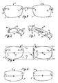
- FIG. 1 shows two lenses and other elements of rimless glasses when viewed from the front.
- the eyeglasses comprise a left eyeglass lens 2, a right eyeglass lens 4 and a bridge 6 disposed between the two eyeglass lenses.
- the terms "left” and “right” refer to the corresponding details of the human head.
- the left lens 2 is assigned to the left eye and in FIG. 1 shown on the right.
- Each of the two lenses 2 and 4 has an in FIG. 1 visible front 3, one in FIG. 1 invisible back, which faces the respective eye of the wearer with glasses attached, and a circumferential edge 5, which limits the lens radially outward.
- the bridge 6 is an elongated element which is arranged between the two lenses 2 and 4 and connects them together, and has at each of its two ends a connecting element 8, which with the in FIG. 1 visible front side 3 of the lens 2 and 4 is glued.
- the glasses also have a left jaw 10 and a right jaw 11.
- the jaws are each attached to an edge region of the spectacle lens 2 or 4 facing away from the bridge.
- each of the two jaws at its front end on a connecting element 12 which is glued to the front side 3 of the spectacle lens 2 and 4 respectively.
- the cheeks are each with a in FIG. 1 not shown bracket of the glasses hinged.
- FIG. 2 shows in perspective view when viewed obliquely from above and behind enlarged and partially the left jaw 10 with its connecting element 12.
- the connecting element 12 of the left jaw has substantially the shape of a cuboid and has on its back a in FIG. 2 visible joining surface 14, which is substantially planar and has the shape of a rectangle, one side of which is rounded, as in FIG. 2 is shown.
- the joining surface 14 is intended to be glued to a joining surface on the front side 3 of the left-hand lens 2.
- the connecting element 12 further comprises an adjacently disposed on the joining surface 14, rearwardly extending projection 16 which is intended to abut the edge 5 of the lens.
- the connecting element 12 passes over into a curved portion 18 of the jaw 10, which connects the connecting element 12 with the hinge, not shown, on which the jaw 10 is connected to the left bracket of the glasses, not shown.
- FIG. 3 shows the bridge 6 enlarged in perspective view when viewed obliquely from above and behind.
- the connecting elements 8 of the bridge 6 the above explanation of the connecting element 12 of the jaw 10 applies. Accordingly, each of the two connecting elements 8 of the bridge 6 has the joining surface 14 and the projection 16 arranged adjacently thereto.
- a strip 20 is formed on this, with the help of the bridge 6 in the FIGS. 1 and 3 not shown web component can be attached, which serves to support the glasses on the nose of the wearer.
- the bridge including its two connecting elements and the jaws including their connecting element are each integrally molded from a plastic injection-molded components.
- the respective connecting elements 8 and 12 on the one hand and the remaining portions of the bridge 6 and the two jaws 10 and 11 on the other hand consist of mutually different materials and have been connected to each other before bonding the connecting elements with the lenses or only after bonding Connecting elements are connected to the lenses together.
- the joining surface 14 is formed, which is intended to be firmly bonded to a complementary joining surface on the front of one of the two lenses.
- the two spectacle lenses 2 and 4 are usually each made of a coated spectacle raw glass having a circular edge.
- the spectacle raw glass is provided on its front and its back with a coating which usually consists of several layers and should provide scratch resistance and / or influencing the reflection properties and / or dirt-repellent properties of the surfaces of the spectacle lens.
- FIG. 4 shows the two lenses 2 and 4 of the glasses according to FIG. 1 in turn, when viewed from the front, wherein the formed on the front sides 3 of the two lenses 2 and 4, explained in more detail below joining surfaces are visible, since the bridge 6 and the jaws 10 and 11 of the glasses in FIG. 4 are not shown.
- the geometric shape of the edge 5 of the two lenses 2 and 4 when viewed from the front (or rear) is referred to as a disk shape.
- the FIGS. 1 and 4 show the lenses 2 and 4 with only one of many possible and known disc shapes.
- FIG. 5 shows in a similar representation as FIG. 4 two lenses 2 and 4, the disc shape can be seen from the disc shape of the lenses in FIG. 4 distinguishes, and thus shows an example of another of the many possible and known disc shapes.
- Each spectacle lens has a geometric center M, which coincides - when viewing the spectacle lens from the front or the rear - with the center of a rectangle designated as a box.
- This box is described below with reference to the in FIG. 4 shown left lens 2 explained in more detail.
- the box is defined by an upper tangent T1 to the edges of the two lenses 2 and 4, a lower tangent T2 to the edges of the two lenses 2 and 4 and an outer tangent T3 and an inner tangent T4 to the edge of the lens 2, wherein the tangents T3 and T4 are perpendicular to the tangents T1 and T2.
- a straight line connecting the centers M of the two spectacle lenses 2 and 4 forms the center line L of each of the two spectacle lenses 2 and 4.
- a glass holder also referred to as a block or adhesive block, is detachably adhered to the front of the spectacle lens, wherein an axis of rotation of the lens holder extends perpendicularly through the front of the spectacle lens and through the geometric center M of the predetermined lens shape of the spectacle lens to be produced , While the spectacle raw glass is rotated about the axis of rotation of the glass holder, so much material is removed from the edge of the spectacle raw glass by grinding in dependence on the rotational position of the spectacle lens, that the spectacle lens is obtained with the desired disc shape.
- the state achieved thereby is exemplary for the left lens 2 in the FIGS. 6 and 7 shown.
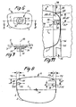
- FIG. 6 shows when viewed from the front, the left lens 2 together with the on the front of the 3 Spectacle lens 2 glued glass holder 22 after grinding the edge 5 with the desired disc shape.
- FIG. 7 shows the lens 2 and the glass holder 22 in section AB in FIG. 6 .
- the glass holder 22 comprises a substantially rectangular or oval plate 24 and a pin 26 arranged centrally thereon. With its free surface, the plate 24 is glued to the lens 2. In the pin 26, a hole is formed, which defines the axis of rotation 28 of the glass holder 22. On the glass holder 22 means are formed, which have a defined relationship to the center line L of the spectacle lens 2. In the in the FIGS. 6 and 7 illustrated example of the glass holder 22, these means are formed by a longitudinal groove 30 which extends in the direction parallel to the center line L of the lens 2.
- joining surfaces 2 and 4 are formed on the front sides 3 of the spectacle lenses, wherein a joining surface is provided on each of the spectacle lenses for each of the joining surfaces 14 of the connecting elements 8 and 12. Accordingly, located on the left lens 2, a joining surface 32 for the left connecting element 8 of the bridge 6 and a joining surface 34 for the connecting element 12 of the left jaw 10 and are located on the right lens 4, a joining surface 36 for the right connecting element 8 of the bridge 6 and a Mating surface 38 for the connecting element 12 of the right jaw 11.
- the two joining surfaces 32 and 36 are also referred to as nasal joining surfaces, since they are in attached glasses near the nose of the wearer, and the two joining surfaces 34 and 38 also referred to as temporal joining surfaces, since they are with attached glasses in the area of the temples.
- the four joining surfaces on the lenses 2 and 4 are similar in shape and dimensions substantially the joining surface 14 of the respective connecting element 8 and 12, which is glued to the lens. In other words, this means that the joining surfaces on the spectacle lenses on the one hand and the joining surfaces on the connecting elements on the other hand are designed to be complementary to one another.
- the joining surfaces on the spectacle lenses 2 and 4 have been formed thereon in that in the region of the joining surfaces to be formed, the coating on the front side of the respective spectacle lens is completely, i. has been removed at least up to the total thickness of the coating.
- the purpose of the removal of the coating is to expose the base material of the lenses, so that the respective joining surface on the lens has the material nature of the base material of the lens. This is a prerequisite for the production of a permanently solid adhesive bond between the connecting elements and the lenses.
- FIG. 8 shows enlarged again when viewed from the front, the left lens 2 of the considered
- the joining surfaces on the front side of the spectacle lens 2 or 4 respectively extend from the edge 5 of the spectacle lens or extend up to this edge.
- Each of the joining surfaces is delimited by two straight lines which are parallel to the center line L of the spectacle lens and whose distance from one another defines the width B of the joining surface, as for the temporal joining surface 34 in FIG FIG. 8 is shown.
- the geometric center M facing end of each of the joining surfaces is limited by a semicircle.
- a joining surface center line FM runs centrally between the two two straight edges of each joining surface, as also shown in FIG FIG. 8 is shown.
- each joining surface on the spectacle lenses is predetermined and determined by the design of the spectacles together with the lens shape of the spectacle lenses 2 and 4.
- the location of the temporal joining surface 34 is predetermined such that its joining surface centerline FM intersects the tangent T3 at its point of contact at the edge 5 of the spectacle lens 2 or near this contact point.
- the location of the nasal joining surface 32 on the left-hand lens 2 is predetermined so that its joining center line FM intersects the tangent T4 at its point of contact at the edge 5 or near this point of contact.
- FIG. 8 a parallel parallel to the tangent T3 parallel P3 is drawn, which has the distance D from the tangent T3 and the edge 5 of the lens 2 intersects in an intersection ST.
- the intersection point ST has the distance DT from the joining surface center line FM of the temporal joining surface 34.
- a running parallel to the tangent T4 parallel P4 which has the distance D from the tangent T4 and the edge 5 of the lens 2 intersects at an intersection SN.
- the intersection point SN has the distance DN from the joining surface center line FM of the nasal joining surface 32.
- the intersections ST and SN are preferably on the same side of the center line L as the joining surfaces.
- both the joining surfaces 32 and 34 and the intersection points ST and SN are above the center line L and that the intersections ST and SN lie on the upper portion of the edge 5 of the spectacle lens 2.
- the values of the distance D are preferably for the nasal Joining surface equal and are usually in the range of 2 to 5 mm.
- the above explanations to the left lens with reference to FIG. 8 apply mutatis mutandis to the right lens 4, since in the embodiment of the rimless glasses according to FIG. 1 whose left half and right half are symmetrical to each other.
- the distance DN is the same for the two nasal joining surfaces 32 and 36, and the distance DT is the same for the two temporal joining surfaces 34 and 38.
- the distances DT and DN are given or fixed to these, so are the distances DT and DN at the same time given or fixed at a given or selected value of the distance D.
- the predetermined distances DT and DN set the locations of Joint surface center lines FM.
- the distance DT can assume different values and usually assumes different values. The same applies to the distance DN.
- each joining surface should be formed as accurately as possible at the predetermined location. It has been found that this high required accuracy can be achieved by utilizing the above-explained geometric relationship between the intersection ST and the temporal mating surface and the geometric relationship between the intersection SN and the nasal mating surface. In the device according to the invention these geometric relationships are used.
- This device is used to edit the lenses of a rimless glasses of the type described above, wherein it is the processing to the formation of the lateral and nasal joining surfaces by removing the coating on the front of the lenses in the region of the joint surfaces to be formed.
- the coating is removed at least up to its entire thickness, it is harmless if at the same time some base material of the lenses is removed.
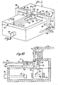
- FIG. 9 shows the embodiment schematically in perspective view when viewed obliquely from above and forward.
- FIG. 10 is a schematic sectional view according to CD in FIG. 9 , where in FIG. 10 the device is shown in conjunction with a lens to be processed.
- the device comprises a housing and a holding device for holding a spectacle lens on or in the device.
- the holding device comprises a support part 40, on which a flat, substantially rectangular support surface 42 is formed, a contact part 44, on which a flat, substantially rectangular contact surface 46 is formed, and a hold-down.
- the bearing surface 42 and the abutment surface 46 adjoin one another and enclose a right angle between them.
- the in FIG. 9 visible support surface 42 is considered as a horizontally oriented surface and accordingly denotes a "vertical" one Course perpendicular to the horizontal support surface 42.
- the abutment surface 46 is an area which extends vertically upward from the support surface 42 from.
- the support member 40 and the abutment member 44 are integrally formed on an upper housing part 48 which carries the hold-down.
- the hold-down comprises a hold-down bar 50, a guide 52 and an actuating lever 54, wherein the guide 52 and the operating lever 54 are shown only schematically in FIG FIG. 10 are shown, but not in FIG. 9 ,
- the hold-down bar 50 is guided vertically in the guide 52 and is held by the guide 52 such that a arranged at the lower end of the hold-down bar 50 elastic member is approximately centrally above the support surface 42.
- a spring acts on the hold-down bar 50 in the downward direction.
- the hold-down rod 50 can be raised against the force of the spring.
- a spectacle lens for example, the right lens 4 are placed with an edge region on the support surface 42 and thereby applied with its edge 5 against the contact surface 46 and in this position by means of the hold-down bar 50 against or on the Support surface 42 are pressed so that the lens between the support member 40 and the hold-down bar 50 is clamped or clamped and the holding device can exercise their holding function in this way.
- the holding device may also be referred to as a clamping device or as a clamping device.
- a drive unit 56 is arranged, to which an electric motor belongs, on the shaft of a chuck 58 is seated.
- a tool 60 is inserted, which is formed in the illustrated embodiment as an end mill, the cutting end face on in the FIGS. 9 and 10 upper end of the tool 60 is formed and has a diameter which is equal to the width B of the joining surfaces to be formed.
- the tool 60 may be formed as a front grinder whose end face carries abrasive grains.
- the drive unit 56 is at a merely schematically in FIG. 10 shown carriage 64, by means of which the drive unit 56 can be moved horizontally on rails not shown within the device or moved. During this movement, the tool 60 is displaced relative to the fixture, with the axis of rotation 62 of the tool 60 sweeping over a plane designated as reference plane RP for purposes of the present description.
- This reference plane RP coincides with the drawing plane of FIG. 10 together and is in FIG. 11 recognizable in plan view.
- the elements of the holding device and the rails for the carriage of the drive unit 56 are arranged in or on the device relative to each other such that the support surface 42 and the abutment surface 46 are perpendicular to the reference plane RP and that the axis of rotation 62 of the tool 60 vertically and thus perpendicular to the support surface 42 extends.
- the tool 60 is moved in the direction perpendicular to its axis of rotation 62 as the drive unit 56 moves or proceed.
- the direction of movement of the tool 60 is to the left in FIG. 10 the forward direction V of the tool and is the opposite direction of movement of the tool 60 whose return direction R.
- a control panel 66 which protrudes from the housing and is hinged to the carriage 64 such that by pivoting the control panel 66 of the carriage 64 and the drive unit 56 are moved and thereby the tool 60 in the forward direction V and return direction R advanced or retracted.
- an unillustrated electric servomotor may be provided, which is coupled to the carriage 64 and can drive it in the forward and reverse directions.
- a stop 68 is arranged, whose position in the direction of movement of the carriage 64 by means of a setting wheel 70 is adjustable.
- the carriage 64 hits during the forward movement of the stop 68, so that is limited by the stop 68, the range of movement of the carriage 64 and thereby in turn of the tool 60 in the forward direction in an adjustable manner.
- a slot 72 is formed, which interrupts the support surface 42 approximately centrally.
- the slot 72 has in the region of the support surface 42 has a width which is slightly larger than the diameter of the end face of the tool 60 and extends in the direction of movement of the tool 60, so that the tool can enter its entry into the slot 72.
- the end face of the tool 60 is slightly above the support surface 42.
- the amount of projection of the end face of the tool 60 with respect to the end surface 42 is adjustable. An easy way to set the extent of the supernatant is to push the tool 60 vertically within the chuck 58 in the desired position and to fix in this position in the chuck 58.
- the extent of the projection of the end face of the tool 60 determines to what depth in the direction perpendicular to the front of the lens material is removed in the region of a joining surface. Accordingly, the supernatant is adjusted according to the desired Abtragtiefe, wherein the desired Abtragtiefe is at least so large that the coating is removed to its entire thickness on the front of the lens.
- the slot 72 merges into a housing 74 formed in the housing recess 48, which makes it possible to move the drive unit 56 so far in the forward direction V that the chuck 58 and the tool 60 a position outside of the slot 72 and in FIG. 10 occupy the left of the support surface 42. In this position, the chuck 58 and tool 60 project upwardly over the top of the housing top 48 so that they are freely accessible. In this position, the tool 60 can be replaced and its vertical position in the chuck 58 can be adjusted.
- the hold-down bar 50 is disposed on the device such that its elastic element is above the slot 72.
- the in FIG. 9 in the foreground area in which the operating part 66 is arranged referred to as the right area
- a lying in the right area element or there position is optionally referred to as right element or right position.
- the area lying on the other side of the reference plane is referred to as the left area and elements and positions located there are referred to as left and left positions, respectively.
- the holding device of the in the FIGS. 9 and 10 shown embodiment a right stop member 76 and a left stop member 78 are assigned.
- the right stop member 76 includes a generally parallelepipedal, horizontally extending leg 80 and a generally parallelepipedal, vertically extending leg 82.
- the leg 80 rests on the support surface 42, is perpendicular to the reference plane RP, and faces at one of the reference planes RP facing front portion 84 on an end face, which is bounded by an edge hereinafter referred to as stop edge 86.
- the stop edge 86 is rectilinear and perpendicular to the bearing surface 42.
- the leg 80 passes into the vertically downwardly extending leg 82 on which an actuator engages, which has a thumbwheel 88 and an adjusting spindle 90.
- the adjusting spindle 90 is engaged with a device-fixed spindle nut, not shown.
- this can be performed with the aid of guide means, not shown, to ensure that the distance of the stop edge 86 from the contact surface 46 during the adjustment and change of the distance of the stop edge 86 from the reference plane RP does not change.
- the above explanation of the right stop member 76 applies mutatis mutandis at the same time for the left stop member 78.
- the left stop member 78 also has the stop edge 86, which is rectilinear and perpendicular to the support surface 42 and whose distance from the reference plane RP is adjustable and changeable.
- FIGS. 11 to 14 explains how by means of the device described above, the lenses of the rimless glasses can be edited, ie how the joining surfaces can be formed on these. It is first based on the FIG. 11 explains how on the right lens 4 whose temporal joining surface 38 is formed.
- each joining surface center line FM can be determined by specifying the distance DT or DN of the joining surface center line FM from the intersection ST or SN of a parallel at a distance D from the tangent T3 or T4 to the edge 5 of the spectacle lens 2 or 4.
- FIG. 11 shows a detail and in plan view of the device according to the FIGS. 9 and 10 in the region of the support surface 42 interrupting slot 72. Further, in FIG. 11 a part of the lens to be processed 4 shown in its processing position, wherein the visible within the edge 5 of the lens 4 elements and contours are seen through the lens through.
- the stop edge 86 of the left stop member 78 is adjusted by means of the left stop member 78 associated actuator so that the distance of the stop edge 86 from the reference plane RP, which will be referred to as distance DR, equal to the distance DT.
- the spectacle lens 4 is aligned such that its center line L is parallel to the reference plane RP.
- the hold-down rod 50 of the blank holder which has previously been held in the raised position, is lowered so that the spectacle lens 4 is clamped between the support surface 42 and the elastic element of the hold-down bar 50 and in this way the spectacle lens is clamped and held in its processing position on or in the holding device.
- FIG. 8 illustrated geometrical relationships between the edge 5 of the lens and the distances D and DT reproduced, so that the joining surface center line FM of the trainees joining surface in the reference plane RP, in which the axis of rotation 62 of the tool 60 is located.
- FIG. 11 and FIG. 10 show the lens 4 in its processing position.
- the housing upper part 48 may be provided with auxiliary lines 92 which run parallel to the reference plane RP (see FIG. 9 ).
- auxiliary lines 92 which run parallel to the reference plane RP (see FIG. 9 ).
- the lead of the tool 60 ends when the carriage 64 reaches the stop 68, which is set so that the joining surface 38 has been formed to a predetermined length. Thereafter, the tool 60 is moved back in the return direction R in the rest position and the lens 4 is released from the holding device and removed.
- the joining surface 38 With high accuracy at the predetermined location for them on the lens 4.
- the essential reason for this high accuracy is that on the device by means of the stop edge 86, the contact surface 46 and the reference plane RP, the geometric relationships can be reproduced that for the spectacle lens through the intersection ST and SN, the tangent T3 and T4. and the joining surface centerline FM are given (see FIG. 8 ).
- the stop edge 86 which touches the edge 5, while the spectacle lens rests against the stop edge 86, corresponds to the point of intersection ST or SN.
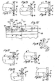
- FIGS. 12 to 14 show in the same plan view as FIG. 11 the processing positions of the lenses 2 and 4 during the formation of the remaining joining surfaces 32, 34 and 36th Den in the FIGS. 11 to 14 shown processing positions that the spectacle lens 2 and 4 rests with the front of the edge region of the spectacle lens in which the joining surface is to be formed on the support surface 42 and that the spectacle lens 2 and 4 rests with its edge 5 on the contact surface 46 , Furthermore, the machining positions have in common that the center line L of the respective Eyeglass lens parallel to the reference plane RP and perpendicular to the contact surface 46 extends.
- FIG. 12 takes the right lens 4, the processing position for the formation of its nasal joining surface 36 a.
- the stop edge 86 of the right stop member 76 is used, on which the spectacle lens 4 abuts with its edge 5.
- the distance DR of the stop edge 86 of the right stopper member 76 from the reference plane RP is set to the distance DN in this case.
- the left stop member 78 and its stop edge are spaced from the lens 4.
- FIG. 13 shows the left lens 2 in the processing position for its nasal joining surface 32.
- the left stop member 78 is used with its stop edge 86 at which abuts the edge of the lens 2.
- the distance DR is set to the distance DN.
- the right stop member 76 and its stop edge are spaced from the lens 2.
- FIG. 14 shows the left lens 2 in the processing position for its temporal joining surface 34.
- the right stop member 76 is used with its stop edge 86 at which the left lens 2 strikes with its edge, but - unlike the case according to FIG. 12 -
- the distance DR is set to the distance DT.
- the left stop member 78 and its stop edge are spaced from the lens 2. In each of the in the FIGS. 12 to 14 shown
- the values of the distance DN and of the distance DT differ.
- the distance DR of each stop edge 86 used from the reference plane RP is continuously adjustable, so that it can be set to different values of DN and DT. Accordingly, the device is suitable for processing spectacle lenses with numerous mutually different disc shapes and for these predetermined locations of the joining surfaces.
- the abutting edge used during the processing of a spectacle lens is formed on a stop member, which is movably guided and held on the other device, so that the distance of the stop edge from the reference plane changed by adjusting the position of the stop member and can be adjusted.
- a second embodiment of the apparatus described below differs from the first embodiment.
- the stop edge is formed on a stop member, which can be detachably mounted to the rest of the device, wherein the distance of the stop edge from the reference plane is variable in that the stop member is mounted on the other device with mutually different orientations.
- FIG. 15 shows the device according to the second embodiment in fragmentary front view, the view when viewed from the left in FIG. 10 corresponds, wherein the elements of the blank holder are not shown.
- a right pin 96 and a left pin 98 are used, which are aligned perpendicular to the support surface 42 and are arranged symmetrically to the reference plane RP, so that their distances DS from the reference plane RP are equal.
- stop member 100 has a cuboid base body 102 and one of them centrally vertically upwardly outgoing handle portion 104.
- the block-shaped base body 102 is provided with two mutually parallel, rectangular end faces 106 and has a bore, which makes it possible to insert the stop member 100 on one of the pins 96 and 98 and thereby mounted on the device.
- FIG. 15 shows the stop member 100 in its mounted on the left pin 98 state.
- the two end surfaces 106 extend parallel to the reference plane RP and two of the sides of the reference plane RP facing end surface 106 perpendicular to the support surface 42, so that the far from the contact surface 46 side of this end face 106 can be used as a stop edge and the Function of the above-explained in connection with the first embodiment stop edge 86 fulfilled.
- the dimensions of the stop member 100 and the location of the pins 96 and 98 are selected so that in the mounted state of the stop member 100 serving as a stop edge 86 side of the two rectangular end faces 106 of the contact surface 46 has the distance DA.
- That of the two end surfaces 106, which is used in the formation of a temporal joining surface and is therefore referred to as a temporal end face and in the FIGS. 15 and 16 is marked with "T” has the distance of the axis of the particular for receiving the pin 98 bore in the main body 102.
- That of the two end surfaces 106, which is used in the formation of a nasal joining surface and is accordingly referred to as a nasal end face and in the FIGS. 15 and 16 is denoted by "N" has the distance LN from the axis of the bore.
- the stop member 100 may be in the in FIG. 15 shown left position on the other device, wherein it is either aligned such that the temporal end face 106 of the reference plane RP faces, as shown in FIG. 15 is shown, or that the nasal face faces the reference plane RP. Further, the abutment member 100 can be mounted by means of the right pin 96 in the right position on the other device and be, wherein the stop member 100 is oriented such that either its temporal face or its nasal face faces the reference plane RP.
- FIGS. 17 to 20 show in a similar representation as the FIGS. 11 to 14 the lenses 2 and 4 in their respective processing positions for the nasal and temporal joining surfaces.
- these figures show the stop member 100 in its respective position and orientation.
- the right lens 4 is shown in its processing position for the temporal joining surface 38.
- the stop member 100 is in its left position, which is also in FIG. 15 is shown, and the stopper member 100 is aligned such that its temporal end face of the reference plane RP faces.
- the spectacle lens strikes against the side of this end face remote from the abutment surface 46, so that the last-mentioned side of the end face forms the abutment edge 86 in this case.
- the distance DA of the stop edge 86 of the contact surface 46 is equal to the above with reference to FIG. 8 explained distance D.
- the distance of the stop edge 86 from the reference plane RP is equal to the distance DT because of based on FIG. 15 explained distance relationships.
- FIG. 18 shows the right lens 4 in its processing position for the nasal joining surface 36.
- the stop member 100 is in its right position, the nasal face of the stop member 100 of the reference plane RP faces and one side of this end face forms the stop edge 86 at the the spectacle lens strikes.
- the distance of this stop edge 86 from the reference plane RP is equal to the distance DN.
- FIG. 19 takes the left lens 2 its processing position for the nasal joining surface 32 a.
- the stop member 100 is in its left position, wherein the nasal face of the stop member 100 faces the reference plane RP and the side facing away from the contact surface 46 of the nasal face forms the stop edge 86 whose distance from the reference plane RP is equal to the distance DN.
- the 20 shows the left lens 2 in its processing position for the temporal joining surface.
- the stop member 100 in its right position, wherein the temporal face of the reference plane RP faces and the side facing away from the contact surface 46 of this end face forms the abutment edge 86.
- the stop edge 86 can be arranged at all locations relative to the reference plane RP by implementing and appropriately aligning the stop member 100 to the rest of the device, for the formation of all four joining surfaces of the two lenses 2 and 4 are required.
- the joining surfaces can be formed only for a specific disc shape, namely that disc shape, are matched to the values of the distances DT, DN and D, the dimensions of the stop member 100.
- the respectively used stop member 100 is one of a plurality of similar stop members of a set of stop members differing in the values of their distances LT and / or LN and optionally the distance DA, each of these stop members of a particular is assigned by several different lens shapes and is then used when lenses are to be processed with this particular disc shape.
- FIGS. 21 and 22 show in a similar representation as the FIGS. 15 and 16 a third embodiment of the Device according to the invention.
- the third embodiment is provided with a stopper member 108 detachably mountable to the rest of the apparatus, which can be mounted on the other apparatus in the left position and the right position, each being differently orientable.
- the third embodiment differs from the second embodiment substantially in terms of the shape of the abutment member.
- the stop member 108 of the third embodiment comprises two legs arranged at right angles to each other, at the free ends of each of which one of the rectangular end faces 106 is formed, for which mutatis mutandis the explanation applies to the end faces 106 of the second embodiment.
- a vertically extending slot 110 is formed, in which each of the two legs of the stop member 108 can be inserted without play in the vertical direction.
- a similar slot 110 is formed on the right side of the device.
- FIG. 21 shows the stop member 108 in its left position and one of the two possible orientations in the left position.
- the provided with the nasal face leg of the stop member 108 is inserted into the left slot 110, and provided with the temporal face leg of the stop member 108 rests on the support surface 42, wherein the dimensions of the stop member 108 are such that the temporal end face and whose two sides perpendicular to the support surface 42 have sides of the reference plane RP the distance DT.
- the leg with the temporal end face is inserted into the slot 110 and the leg with the nasal end face of the reference plane RP faces, the nasal face and its two sides perpendicular to the support surface 42 sides of the reference plane RP the distance DN.
- stop member 108 If the stop member 108 is inserted with one of its two legs in the right slot 110 and the stop member 108 assumes its right position, resulting in conditions that are analogous to those explained above for the stop member 108 in its left position.
- FIGS. 17 to 20 explained geometric relationships between the lenses in their processing positions and the respective stop edge 86 apply equally to the third embodiment and are therefore not explained again.
- This alignment process is carried out manually by the operator, for example, while he the course of the rod 94 (see FIG. 10 ) in relation to the auxiliary lines 92.
- each of the embodiments described above may be provided with a receiving device which holds the lens to be processed such that its center line L is always parallel to the reference plane RP.
- An embodiment of such a receiving device is in FIG. 23 shown, which is a partial and schematic representation in section according to CD in FIG. 9 ie in the same section plane as in FIG. 10 , acts.
- receiving device comprises a cross table 112, which is inside the device as a whole in Substantially perpendicular to the contact surface 46 is movable or movable.
- An upper part 114 of the cross table 112 can be moved or moved at its lower part 116 horizontally substantially perpendicular to the reference plane RP.
- the top 114 carries a guide member 118 which is guided on the upper part 114 substantially vertically displaceable and acts on a vertically upward spring force.
- a receiving part 120 is arranged, which is pivotable relative to the guide part about a pivot axis which is substantially perpendicular to the reference plane RP.
- the receiving part 120 is formed such that it is a glass holder 22 from the basis of FIGS. 6 and 7 can record type described.
- the glass holder 22 accommodated by the receiving part 120 or inserted into the receiving part 120 is held in a rotationally fixed manner by the receiving part 120, i. held such that the glass holder 22 on the receiving part 120 can not rotate about the rotation axis 28 of the glass holder 22.
- the receiving part 120 holds the glass holder 22 in a position such that the center line L of the glass lens glued to the glass holder 22 runs parallel to the reference plane RP.
- the center line L of the Eyeglass lens In these movements the center line L of the Eyeglass lens, however, always aligned parallel to the reference plane RP.
- the lens disposed on the receiving device can perform all the movements that are required to bring it into its processing position in and on the holding device. In these movements, the center line L of the spectacle lens always remains aligned parallel to the reference plane RP, so that the operator need not worry about this alignment.
- the device described above with reference to the exemplary embodiments for forming joining surfaces on the spectacle lenses of rimless spectacles is structurally comparatively simple and enables simple and reliable handling and operation. It makes it possible, in particular, to form the joint surfaces exactly at the locations intended for the joining surfaces on the spectacle lenses.
- the device is suitable for the formation of the joining surfaces on the spectacle lenses for numerous different disc shapes and for the respective disc shape predetermined locations of the joining surfaces.
- the holding device for holding the spectacle lens to be machined is fixed to the apparatus and the drive unit 56 and the tool 60 carried by it are movable or movable. Notwithstanding this, the drive unit 56 and the tool 60 can be arranged fixed to the device and the holding device relative to the tool 60 in the forward direction V and return direction R can be moved.
- This mobility can be achieved in the described embodiments, for example, characterized in that the upper housing part 48 is slidably guided with the arranged thereon elements of the holding device and arranged thereon at least one stop member on the lower housing part.
- the invention is not limited to the described embodiments.
- the device for processing a spectacle lens by removing material in the region of a joining surface to be formed comprises a tool provided with a cutting end face, the axis of rotation of which is movable in a forward direction relative to a holding device and thereby passes over a reference plane.
- the holding device comprises a support surface, a vertically aligned contact surface and a stop edge.
- the support surface and the abutment surface are perpendicular to the reference plane, and the abutment edge is perpendicular to the support surface and parallel to the reference plane and has a distance from the reference plane, which is variable.
- the support surface is interrupted so that the projecting end face of the tool can be moved along the interruption.
- the spectacle lens In its processing position, the spectacle lens rests on the support surface, it rests against the contact surface and strikes it with its edge against the stop edge. If the distance of the abutment edge from the reference plane is set to a predetermined value for the spectacle lens to be processed, the joining surface is formed by means of the tool exactly at the location of the joining surface predetermined for the spectacle lens.
Landscapes
- Engineering & Computer Science (AREA)
- Mechanical Engineering (AREA)
- Chemical & Material Sciences (AREA)
- Ceramic Engineering (AREA)
- Inorganic Chemistry (AREA)
- Grinding And Polishing Of Tertiary Curved Surfaces And Surfaces With Complex Shapes (AREA)
- Eyeglasses (AREA)
Description
- Die Erfindung bezieht sich auf eine Vorrichtung zum Bearbeiten eines Brillenglases einer randlosen Brille, wobei es sich bei der Bearbeitung um das Abtragen von Material auf der Vorderseite des Brillenglases im Bereich von auszubildenden Fügeflächen handelt.
- Durch das Dokument
EP 2 019 331 A1 ist ein Verfahren zur Herstellung einer randlosen Brille bekannt, bei der Verbindungselemente der Backen und der Brücke der Brille mit den Vorderseiten der Brillengläser verklebt sind. Bei diesem bekannten Verfahren werden zunächst zwei Brillen-Rohgläser aus einem Kunststoff gefertigt, auf deren Vorder-und Rückseite eine Beschichtung aufgebracht wird. Die zwei beschichteten Brillen-Rohgläser werden in der Weise geschliffen, dass zwei Brillengläser mit einer gewünschten Scheibenform erhalten werden. An vorbestimmten Anbringungsorten für die Verbindungselemente der Backen und der Brücke auf der Vorderseite der Brillengläser wird die Beschichtung zur Bildung von Fügeflächen abgetragen, die in Gestalt und Abmessungen im Wesentlichen an den Verbindungselementen ausgebildeten Fügeflächen entsprechen. Die Verbindungselemente werden dann mit der Vorderseite der Brillengläser an den Anbringungsorten verklebt. Da im Bereich der Fügeflächen an den Brillengläsern deren Grundmaterial freiliegt, kann eine dauerhaft feste Klebeverbindung zwischen den Verbindungselementen und den Brillengläsern hergestellt werden. - Durch das Dokument
EP 2 091 331 A1 ist ferner eine bei dem vorstehend erläuterten Verfahren einsetzbare Vorrichtung zur Ausbildung der Fügeflächen auf den Vorderseiten der Brillengläser durch örtliches Abtragen der Beschichtung im Bereich der auszubildenden Fügeflächen bekannt, die die im Oberbegriff von Patentanspruch 1 aufgeführten Merkmale aufweist. Die bekannte Vorrichtung umfasst eine Montageplatte sowie für jedes Brillenglas der herzustellenden Brille eine Haltevorrichtung, mit deren Hilfe das Brillenglas an der Montageplatte derart fixiert wird, dass seine Vorderseite von der Montageplatte abgewandt ist und freiliegt. Eine Schleifvorrichtung umfasst eine Antriebseinheit und ein von der Antriebseinheit getragenes Werkzeug, das als Stirnschleifer ausgebildet ist. Die Schleifvorrichtung kann unter Steuerung durch eine Programmsteuervorrichtung über den Ort, an dem eine einzelne Fügefläche auszubilden ist, gefahren werden, wird dort abgesenkt, bis die Stirnfläche des Stirnschleifers mit geringer Anpresskraft in Kontakt mit dem Brillenglas steht und schleift dann örtlich die Beschichtung ab, um dadurch eine Fügefläche am Brillenglas auszubilden. Es hat sich als schwierig erwiesen, mittels der bekannten Vorrichtung die Fügeflächen genau an den für diese vorgegebenen Orten auf der Vorderseite des Brillenglases auszubilden. - Der Erfindung liegt die Aufgabe zugrunde, eine Vorrichtung zum Bearbeiten eines Brillenglases einer randlosen Brille zu schaffen, die es ermöglicht, Fügeflächen an dem Brillenglas mit hoher Genauigkeit an vorbestimmten bzw. vorgegebenen Orten des Brillenglases auszubilden. Die zu schaffende Vorrichtung soll konstruktiv möglichst einfach ausgebildet sein und eine einfache Handhabung und Bedienung ermöglichen.
- Diese Aufgabe wird erfindungsgemäß gelöst durch die Vorrichtung gemäß Patentanspruch 1. Die erfindungsgemäße Vorrichtung weist die Auflagefläche, die Anlagefläche und den Niederhalter sowie die zumindest eine Anschlagkante auf. Diese Elemente stehen in der im Patentanspruch 1 näher definierten Beziehung zu dem Werkzeug und der von ihm überstrichenen Bezugsebene und ermöglichen es im Zusammenwirken, das Brillenglas in einer solchen Bearbeitungsposition anzuordnen und zu halten bzw. einzuspannen, dass das Werkzeug die auszubildende Fügefläche genau an dem für das Brillenglas unter Berücksichtigung seiner Scheibenform vorgegebenen Ort der Fügefläche ausbildet.
- Vorteilhafte Ausgestaltungen der Erfindung sind in den abhängigen Ansprüchen definiert.
- Die Erfindung wird im Folgenden anhand von Ausführungsbeispielen unter Bezugnahme auf die Zeichnungen näher erläutert. Es zeigen:
-
Figur 1 eine Vorderansicht eines Ausführungsbeispiels einer randlosen Brille, bei deren Herstellung die erfindungsgemäße Vorrichtung zur Anwendung kommen kann; -
Figur 2 eine perspektivische Ansicht einer linken Backe der Brille gemäßFigur 1 ; -
Figur 3 eine perspektivische Ansicht einer Brücke der Brille gemäßFigur 1 ; -
Figur 4 die beiden Brillengläser der Brille gemäßFigur 1 in Vorderansicht; -
Figur 5 zwei Brillengläser in Vorderansicht, die sich durch ihre Scheibenform von den Brillengläsern gemäß denFiguren 1 und 4 unterscheiden; -
Figur 6 eine Vorderansicht eines Brillenglases der Brille gemäßFigur 1 in Verbindung mit einem Glashalter nach dem Anschleifen der Scheibenform an dem Brillenglas; -
Figur 7 eine Schnittdarstellung gemäß A-B inFigur 6 ; -
Figur 8 eine vergrößerte Vorderansicht eines linken Brillenglases der Brille gemäßFigur 1 zur Erläuterung von geometrischen Beziehungen zwischen Fügeflächen des Brillenglases und dessen Rand; -
Figur 9 eine schematische perspektivische Darstellung eines ersten Ausführungsbeispiels der erfindungsgemäßen Vorrichtung bei Betrachtung von schräg oben und vorn; -
Figur 10 eine schematische Schnittdarstellung des ersten Ausführungsbeispiels der Vorrichtung im Schnitt gemäß C-D inFigur 9 ; -
Figur 11 eine ausschnittsweise Draufsicht auf die Vorrichtung gemäß denFiguren 9 und 10 während der Bearbeitung eines rechten Brillenglases der Brille gemäßFigur 1 mittels der Vorrichtung; -
Figuren 12 bis 14 in ähnlicher Darstellung wie inFigur 11 zwei Brillengläser und Elemente der Vorrichtung während der Bearbeitung der Brillengläser, wobei die Brillengläser in verschiedenen Bearbeitungspositionen gezeigt sind; -
Figur 15 eine ausschnittsweise, schematische Vorderansicht eines zweiten Ausführungsbeispiels der erfindungsgemäßen Vorrichtung; -
Figur 16 eine perspektivische Darstellung eines Anschlagteils der Vorrichtung gemäßFigur 15 ; -
Figuren 17 bis 20 in ähnlicher Darstellung wie in den -
Figuren 11 bis 14 zwei Brillengläser in verschiedenen Bearbeitungspositionen und zugeordnete Elemente der Vorrichtung gemäß denFiguren 15 und 16 ; -
Figur 21 eine ausschnittsweise, schematische Vorderansicht eines dritten Ausführungsbeispiels der erfindungsgemäßen Vorrichtung; -
Figur 22 eine perspektivische Darstellung eines Anschlagteils der Vorrichtung gemäßFigur 21 ; und -
Figur 23 ausschnittsweise und schematisch eine Aufnahmevorrichtung, die bei der erfindungsgemäßen Vorrichtung vorgesehen sein kann. - Im Folgenden wird zunächst anhand der
Figuren 1 bis 4 und6 bis 8 ein Ausführungsbeispiel einer randlosen Brille erläutert, bei deren Herstellung die erfindungsgemäße Vorrichtung zur Anwendung kommen kann. -
Figur 1 zeigt zwei Brillengläser sowie weitere Elemente einer randlosen Brille bei Betrachtung von vorn. Die Brille umfasst ein linkes Brillenglas 2, ein rechtes Brillenglas 4 und eine zwischen den beiden Brillengläsern angeordnete Brücke 6. In der vorliegenden Erläuterung der Brille beziehen sich die Begriffe "links" und "rechts" auf die entsprechenden Angaben zum menschlichen Kopf. Dementsprechend ist beispielsweise das linke Brillenglas 2 dem linken Auge zugeordnet und inFigur 1 rechts dargestellt. Jedes der beiden Brillengläser 2 und 4 hat eine inFigur 1 sichtbare Vorderseite 3, eine inFigur 1 nicht sichtbare Rückseite, die bei aufgesetzter Brille dem jeweiligen Auge des Brillenträgers zugewandt ist, und einen umlaufenden Rand 5, der das Brillenglas radial außen begrenzt. Die Brücke 6 ist ein langgestrecktes Element, das zwischen den beiden Brillengläsern 2 und 4 angeordnet ist und diese miteinander verbindet, und weist an jedem ihrer beiden Enden ein Verbindungselement 8 auf, das mit der inFigur 1 sichtbaren Vorderseite 3 des Brillenglases 2 bzw. 4 verklebt ist. Die Brille weist ferner eine linke Backe 10 und eine rechte Backe 11 auf. Die Backen sind jeweils an einem von der Brücke abgewandten Randbereich des Brillenglases 2 bzw. 4 befestigt. Zu diesem Zweck weist jede der beiden Backen an ihrem vorderen Ende ein Verbindungselement 12 auf, das mit der Vorderseite 3 des Brillenglases 2 bzw. 4 verklebt ist. Die Backen sind jeweils mit einem inFigur 1 nicht dargestellten Bügel der Brille gelenkig verbunden. -
Figur 2 zeigt in perspektivischer Darstellung bei Betrachtung von schräg oben und hinten vergrößert und ausschnittsweise die linke Backe 10 mit ihrem Verbindungselement 12. Das Verbindungselement 12 der linken Backe hat im Wesentlichen die Gestalt eines Quaders und weist auf seiner Rückseite eine inFigur 2 sichtbare Fügefläche 14 auf, die im Wesentlichen eben ist und die Gestalt eines Rechtecks hat, dessen eine Seite abgerundet ist, wie dies inFigur 2 gezeigt ist. Die Fügefläche 14 ist dazu bestimmt, mit einer Fügefläche auf der Vorderseite 3 des linken Brillenglases 2 verklebt zu werden. Das Verbindungselement 12 umfasst ferner einen angrenzend an die Fügefläche 14 angeordneten, sich nach hinten erstreckenden Vorsprung 16, der dazu bestimmt ist, am Rand 5 des Brillenglases anzuliegen. Das Verbindungselement 12 geht über in einen gekrümmten Abschnitt 18 der Backe 10, der das Verbindungselement 12 mit dem nicht dargestellten Gelenk verbindet, an dem die Backe 10 mit dem nicht dargestellten linken Bügel der Brille verbunden ist. - Die vorstehende Erläuterung der linken Backe 10 gilt sinngemäß auch für die rechte Backe 11 der Brille.
-
Figur 3 zeigt die Brücke 6 vergrößert in perspektivischer Darstellung bei Betrachtung von schräg oben und hinten. Hinsichtlich der Ausbildung der Verbindungselemente 8 der Brücke 6 gilt die vorstehende Erläuterung des Verbindungselementes 12 der Backe 10. Dementsprechend weist jedes der beiden Verbindungselemente 8 der Brücke 6 die Fügefläche 14 und den angrenzend an diese angeordneten Vorsprung 16 auf. Im mittleren Abschnitt der Brücke 6 ist an dieser eine Leiste 20 angeformt, mit deren Hilfe an der Brücke 6 ein in denFiguren 1 und 3 nicht dargestelltes Stegbauteil befestigt werden kann, das zur Abstützung der Brille an der Nase des Brillenträgers dient. - Bei dem vorstehend beschriebenen Ausführungsbeispiel einer randlosen Brille sind die Brücke einschließlich ihrer beiden Verbindungselemente und die Backen einschließlich ihres Verbindungselementes jeweils einstückig aus einem Kunststoff spritzgegossene Bauteile. Abweichend hiervon können die jeweiligen Verbindungselemente 8 bzw. 12 einerseits und die übrigen Abschnitte der Brücke 6 und der beiden Backen 10 und 11 andererseits aus voneinander verschiedenen Werkstoffen bestehen und vor dem Verkleben der Verbindungselemente mit den Brillengläsern miteinander verbunden worden sein oder erst nach dem Verkleben der Verbindungselemente mit den Brillengläsern miteinander verbunden werden. Beispielsweise ist es möglich, das jeweilige Verbindungselement am übrigen Abschnitt der Brücke oder Backe in einem Spritzgießverfahren anzuspritzen und dabei den übrigen Abschnitt mit dem Werkstoff des Verbindungselementes teilweise oder vollständig zu ummanteln. Unabhängig von der übrigen Ausbildung und dem Herstellungsverfahren der Brücke und der Backen ist wesentlich, dass an dem jeweiligen Verbindungselement die Fügefläche 14 ausgebildet ist, die dazu bestimmt ist, mit einer komplementären Fügefläche auf der Vorderseite eines der beiden Brillengläser fest verklebt zu werden.
- Die beiden Brillengläser 2 und 4 sind üblicherweise jeweils aus einem beschichteten Brillen-Rohglas hergestellt worden, das einen kreisförmigen Rand aufweist. Das Brillen-Rohglas ist auf seiner Vorderseite und seiner Rückseite mit einer Beschichtung versehen, die üblicherweise aus mehreren Schichten besteht und für Kratzfestigkeit und/oder Beeinflussung der Reflexionseigenschaften und/oder Schmutz abweisende Eigenschaften der Oberflächen des Brillenglases sorgen soll.
-
Figur 4 zeigt die zwei Brillengläser 2 und 4 der Brille gemäßFigur 1 wiederum bei Betrachtung von vorn, wobei die auf den Vorderseiten 3 der beiden Brillengläser 2 und 4 ausgebildeten, weiter unten näher erläuterten Fügeflächen sichtbar sind, da die Brücke 6 und die Backen 10 und 11 der Brille inFigur 4 nicht dargestellt sind. Die geometrische Gestalt des Randes 5 der beiden Brillengläser 2 und 4 bei Betrachtung von vorn (oder hinten) wird als Scheibenform bezeichnet. Es sind zahlreiche verschiedene Scheibenformen bekannt und bei randlosen Brillen möglich. DieFiguren 1 und 4 zeigen die Brillengläser 2 und 4 mit lediglich einer von zahlreichen möglichen und bekannten Scheibenformen. -
Figur 5 zeigt in ähnlicher Darstellung wieFigur 4 zwei Brillengläser 2 und 4, deren Scheibenform sich erkennbar von der Scheibenform der Brillengläser inFigur 4 unterscheidet, und zeigt somit ein Beispiel für eine weitere der zahlreichen möglichen und bekannten Scheibenformen. - Jedes Brillenglas hat einen geometrischen Mittelpunkt M, der - bei Betrachtung des Brillenglases von vorn oder hinten - zusammenfällt mit dem Mittelpunkt eines als Kasten bezeichneten Rechtecks. Dieser Kasten wird im Folgenden anhand des in
Figur 4 gezeigten linken Brillenglases 2 näher erläutert. Der Kasten ist definiert durch eine obere Tangente T1 an die Ränder der beiden Brillengläser 2 und 4, eine untere Tangente T2 an die Ränder der beiden Brillengläser 2 und 4 sowie eine äußere Tangente T3 und eine innere Tangente T4 an den Rand des Brillenglases 2, wobei die Tangenten T3 und T4 senkrecht zu den Tangenten T1 und T2 verlaufen. Eine die Mittelpunkte M der beiden Brillengläser 2 und 4 verbindende Gerade bildet die Mittellinie L jedes der beiden Brillengläser 2 und 4. - Um die Brillengläser 2 und 4 mit der gewünschten, beispielsweise der in
Figuren 1 und 4 gezeigten Scheibenform herzustellen, wird üblicherweise ein auch als Block oder Klebeblock bezeichneter Glashalter auf der Vorderseite des Brillen-Rohglases lösbar angeklebt, wobei eine Drehachse des Glashalters senkrecht durch die Vorderseite des Brillen-Rohglases und durch den geometrischen Mittelpunkt M der vorbestimmten Scheibenform des herzustellenden Brillenglases verläuft. Während das Brillen-Rohglas um die Drehachse des Glashalters gedreht wird, wird vom Rand des Brillen-Rohglases ausgehend von diesem durch Schleifen in Abhängigkeit von der Drehstellung des Brillen-Rohglases so viel Material entfernt, dass das Brillenglas mit der gewünschten Scheibenform erhalten wird. Der dabei erreichte Zustand ist beispielhaft für das linke Brillenglas 2 in denFiguren 6 und 7 dargestellt. -
Figur 6 zeigt bei Betrachtung von vorn das linke Brillenglas 2 zusammen mit dem auf der Vorderseite 3 des Brillenglases 2 angeklebten Glashalter 22 nach dem Anschleifen des Randes 5 mit der gewünschten Scheibenform. -
Figur 7 zeigt das Brillenglas 2 und den Glashalter 22 im Schnitt gemäß A-B inFigur 6 . - Der Glashalter 22 umfasst eine im Wesentlichen rechteckige oder ovale Platte 24 und einen mittig daran angeordneten Zapfen 26. Mit ihrer freien Oberfläche ist die Platte 24 am Brillenglas 2 angeklebt. Im Zapfen 26 ist ein Loch ausgebildet, das die Drehachse 28 des Glashalters 22 definiert. Am Glashalter 22 sind Mittel ausgebildet, die eine definierte Beziehung zu der Mittellinie L des Brillenglases 2 haben. Bei dem in den
Figuren 6 und 7 dargestellten Beispiel des Glashalters 22 sind diese Mittel durch eine Längsnut 30 gebildet, die sich in Richtung parallel zur Mittellinie L des Brillenglases 2 erstreckt. - Wie bereits vorstehend beschrieben ist, sind die Brücke und die Backen der Brille mit den Brillengläsern 2 und 4 verklebt. Zu diesem Zweck sind auf den Vorderseiten 3 der Brillengläser 2 und 4 Fügeflächen ausgebildet, wobei an den Brillengläsern für jede der Fügeflächen 14 der Verbindungselemente 8 und 12 jeweils eine Fügefläche vorgesehen ist. Dementsprechend befinden sich am linken Brillenglas 2 eine Fügefläche 32 für das linke Verbindungselement 8 der Brücke 6 sowie eine Fügefläche 34 für das Verbindungselement 12 der linken Backe 10 und befinden sich am rechten Brillenglas 4 eine Fügefläche 36 für das rechte Verbindungselement 8 der Brücke 6 sowie eine Fügefläche 38 für das Verbindungselement 12 der rechten Backe 11. Im Folgenden werden die beiden Fügeflächen 32 und 36 auch als nasale Fügeflächen bezeichnet, da sie sich bei aufgesetzter Brille nahe der Nase des Brillenträgers befinden, und werden die beiden Fügeflächen 34 und 38 auch als temporale Fügeflächen bezeichnet, da sie sich bei aufgesetzter Brille im Bereich der Schläfen befinden. Die vier Fügeflächen an den Brillengläsern 2 und 4 gleichen in Form und Abmessungen im Wesentlichen der Fügefläche 14 des jeweiligen Verbindungselementes 8 bzw. 12, das an dem Brillenglas angeklebt ist. Dies heißt mit anderen Worten, dass die Fügeflächen an den Brillengläsern einerseits und die Fügeflächen an den Verbindungselementen andererseits zueinander komplementär gestaltet sind.
- Die Fügeflächen an den Brillengläsern 2 und 4 sind an diesen dadurch ausgebildet worden, dass im Bereich der auszubildenden Fügeflächen die Beschichtung auf der Vorderseite des jeweiligen Brillenglases vollständig, d.h. zumindest bis zur gesamten Dicke der Beschichtung abgetragen worden ist. Der Zweck des Abtragens der Beschichtung besteht darin, das Grundmaterial der Brillengläser freizulegen, damit die jeweilige Fügefläche am Brillenglas die stoffliche Beschaffenheit des Grundmaterials des Brillenglases hat. Dies ist Voraussetzung für die Herstellung einer dauerhaft festen Klebeverbindung zwischen den Verbindungselementen und den Brillengläsern.
-
Figur 8 zeigt vergrößert wiederum bei Betrachtung von vorn das linke Brillenglas 2 des betrachteten - Ausführungsbeispiels der randlosen Brille. Bei diesem Ausführungsbeispiel gehen die Fügeflächen auf der Vorderseite des Brillenglases 2 bzw. 4 jeweils vom Rand 5 des Brillenglases aus bzw. erstrecken sie sich bis zu diesem Rand. Jede der Fügeflächen ist durch zwei zu der Mittellinie L des Brillenglases parallele Geraden begrenzt, deren Abstand voneinander die Breite B der Fügefläche definiert, wie dies für die temporale Fügefläche 34 in
Figur 8 gezeigt ist. An ihrem dem geometrischen Mittelpunkt M zugewandten Ende ist jede der Fügeflächen durch einen Halbkreis begrenzt. Eine Fügeflächenmittellinie FM verläuft mittig zwischen den zwei beiden geraden Rändern einer jeden Fügefläche, wie dies ebenfalls inFigur 8 gezeigt ist. - Der Ort einer jeden Fügefläche an den Brillengläsern ist durch das Design der Brille zusammen mit der Scheibenform der Brillengläser 2 und 4 vorgegeben und festgelegt. Dabei ist der Ort der temporalen Fügefläche 34 derart vorgegeben, dass deren Fügeflächenmittellinie FM die Tangente T3 in deren Berührungspunkt am Rand 5 des Brillenglases 2 oder nahe diesem Berührungspunkt schneidet. Der Ort der nasalen Fügefläche 32 am linken Brillenglas 2 ist derart vorgegeben, dass deren Fügeflächenmittellinie FM die Tangente T4 an deren Berührungspunkt am Rand 5 oder nahe diesem Berührungspunkt schneidet.
- In
Figur 8 ist eine zu der Tangente T3 parallel verlaufende Parallele P3 eingezeichnet, die von der Tangente T3 den Abstand D hat und den Rand 5 des Brillenglases 2 in einem Schnittpunkt ST schneidet. Der Schnittpunkt ST hat von der Fügeflächenmittellinie FM der temporalen Fügefläche 34 den Abstand DT. Ferner ist inFigur 8 eine zu der Tangente T4 parallel verlaufende Parallele P4 eingezeichnet, die von der Tangente T4 den Abstand D hat und den Rand 5 des Brillenglases 2 in einem Schnittpunkt SN schneidet. Der Schnittpunkt SN hat von der Fügeflächenmittellinie FM der nasalen Fügefläche 32 den Abstand DN. Die Schnittpunkte ST und SN liegen vorzugsweise auf derselben Seite der Mittellinie L wie die Fügeflächen. FürFigur 8 bedeutet dies, dass sowohl die Fügeflächen 32 und 34 als auch die Schnittpunkte ST und SN oberhalb der Mittellinie L liegen und das die Schnittpunkte ST und SN auf dem oberen Abschnitt des Randes 5 des Brillenglases 2 liegen. Die Werte des Abstandes D sind vorzugsweise für die nasale Fügefläche gleich und liegen üblicherweise im Bereich von 2 bis 5 mm. - Die vorstehenden Erläuterungen zum linken Brillenglas anhand von
Figur 8 gelten sinngemäß für das rechte Brillenglas 4, da bei dem Ausführungsbeispiel der randlosen Brille gemäßFigur 1 deren linke Hälfte und rechte Hälfte symmetrisch zueinander ausgebildet sind. Der Abstand DN ist für die beiden nasalen Fügeflächen 32 und 36 der gleiche, und der Abstand DT ist für die beiden temporalen Fügeflächen 34 und 38 der gleiche. - Wenn die Scheibenform der Brillengläser und die Orte der Fügeflächen an diesen vorgegeben bzw. festgelegt sind, sind damit zugleich die Abstände DT und DN vorgegeben bzw. festgelegt bei gegebenem bzw. gewähltem Wert des Abstandes D. Die vorgegebenen Abstände DT und DN legen die Orte der Fügeflächenmittellinien FM fest. Je nach vorgegebener Scheibenform und vorgegebenen Orten der Fügeflächen kann der Abstand DT verschiedene Werte annehmen und nimmt er üblicherweise verschiedene Werte an. Gleiches gilt für den Abstand DN.
- Wenn im Zuge der Fertigung der randlosen Brille die nasalen Fügeflächen 32 und 36 und die temporalen Fügeflächen 34 und 38 ausgebildet werden, soll dies mit hoher Genauigkeit erfolgen, d.h. soll jede Fügefläche möglichst genau an dem vorgegeben Ort ausgebildet werden. Es ist gefunden worden, dass diese hohe geforderte Genauigkeit erreicht werden kann unter Ausnutzung der vorstehend erläuterten geometrischen Beziehung zwischen dem Schnittpunkt ST und der temporalen Fügefläche und der geometrischen Beziehung zwischen dem Schnittpunkt SN und der nasalen Fügefläche. Bei der erfindungsgemäßen Vorrichtung werden diese geometrischen Beziehungen genutzt.
- Im Folgenden wird insbesondere unter Bezugnahme auf die
Figuren 9 bis 14 ein erstes Ausführungsbeispiel der erfindungsgemäßen Vorrichtung erläutert. Diese Vorrichtung dient zum Bearbeiten der Brillengläser einer randlosen Brille der vorstehend erläuterten Art, wobei es sich bei der Bearbeitung um das Ausbilden der lateralen und nasalen Fügeflächen durch Abtragen der Beschichtung auf der Vorderseite der Brillengläser im Bereich der auszubildenden Fügeflächen handelt. Die Beschichtung wird dabei zumindest bis zu ihrer gesamten Dicke abgetragen, wobei es unschädlich ist, wenn zugleich etwas Grundmaterial der Brillengläser abgetragen wird. -
Figur 9 zeigt das Ausführungsbeispiel schematisch in perspektivischer Darstellung bei Betrachtung von schräg oben und vorn. -
Figur 10 ist eine schematische Schnittdarstellung gemäß C-D inFigur 9 , wobei inFigur 10 die Vorrichtung in Verbindung mit einem zu bearbeitenden Brillenglas dargestellt ist. - Die Vorrichtung gemäß dem dargestellten Ausführungsbeispiel umfasst ein Gehäuse und eine Haltevorrichtung zum Halten eines Brillenglases an bzw. in der Vorrichtung. Die Haltevorrichtung umfasst ein Auflageteil 40, an dem eine ebene, im Wesentlichen rechteckige Auflagefläche 42 ausgebildet ist, ein Anlageteil 44, an dem eine ebene, im Wesentlichen rechteckige Anlagefläche 46 ausgebildet ist, sowie einen Niederhalter. Die Auflagefläche 42 und die Anlagefläche 46 grenzen aneinander und schließen zwischen sich einen rechten Winkel ein. Für die Zwecke der vorliegenden Beschreibung wird die in
Figur 9 sichtbare Auflagefläche 42 als horizontal ausgerichtete Fläche angesehen und bezeichnet dementsprechend "vertikal" einen Verlauf senkrecht zu der horizontalen Auflagefläche 42. Dementsprechend ist die Anlagefläche 46 eine Fläche, die sich vertikal nach oben von der Auflagefläche 42 aus erstreckt. - Bei dem dargestellten Ausführungsbeispiel sind das Auflageteil 40 und das Anlageteil 44 einstückig an einem Gehäuseoberteil 48 ausgebildet, das den Niederhalter trägt. Der Niederhalter umfasst eine Niederhaltestange 50, eine Führung 52 und einen Betätigungshebel 54, wobei die Führung 52 und der Betätigungshebel 54 lediglich schematisch in
Figur 10 gezeigt sind, nicht jedoch inFigur 9 . Die Niederhaltestange 50 ist vertikal in der Führung 52 geführt und wird von der Führung 52 derart gehalten, dass sich ein am unteren Ende der Niederhaltestange 50 angeordnetes elastisches Element etwa mittig oberhalb der Auflagefläche 42 befindet. Eine nicht dargestellte Feder beaufschlagt die Niederhaltestange 50 in Richtung nach unten. Mittels des Betätigungshebels 54 kann die Niederhaltestange 50 entgegen der Kraft der Feder angehoben werden. - Auf weiter unten näher beschriebene Weise kann ein Brillenglas, beispielsweise das rechte Brillenglas 4, mit einem Randbereich auf die Auflagefläche 42 aufgelegt werden und dabei mit seinem Rand 5 gegen die Anlagefläche 46 angelegt werden und in dieser Stellung mittels der Niederhaltestange 50 gegen bzw. auf die Auflagefläche 42 gedrückt werden, so dass das Brillenglas zwischen dem Auflageteil 40 und der Niederhaltestange 50 eingeklemmt bzw. eingespannt ist und die Haltevorrichtung auf diese Weise ihre Haltefunktion ausüben kann. Dementsprechend kann die Haltevorrichtung auch als Einspannvorrichtung oder als Klemmvorrichtung bezeichnet werden.
- Innerhalb des Gehäuses der Vorrichtung ist eine Antriebseinheit 56 angeordnet, zu der ein Elektromotor gehört, auf dessen Welle ein Spannfutter 58 sitzt. In das Spannfutter 58 ist ein Werkzeug 60 eingesetzt, das bei dem dargestellten Ausführungsbeispiel als Stirnfräser ausgebildet ist, dessen spanende Stirnfläche am in den
Figuren 9 und 10 oberen Ende des Werkzeugs 60 ausgebildet ist und einen Durchmesser hat, der gleich der Breite B der auszubildenden Fügeflächen ist. Alternativ kann das Werkzeug 60 als Stirnschleifer ausgebildet sein, dessen Stirnfläche Schleifkörner trägt. Mittels der Antriebseinheit 56 kann das Werkzeug 60 um dessen Drehachse 62 gedreht werden. - Die Antriebseinheit 56 ist an einem lediglich schematisch in
Figur 10 gezeigten Schlitten 64 befestigt, mittels dessen die Antriebseinheit 56 auf nicht dargestellten Schienen innerhalb der Vorrichtung horizontal bewegt bzw. verfahren werden kann. Während dieser Bewegung wird das Werkzeug 60 relativ zu der Haltevorrichtung verlagert bzw. bewegt, wobei die Drehachse 62 des Werkzeugs 60 eine Ebene überstreicht bzw. definiert, die für die Zwecke der vorliegenden Beschreibung als Bezugsebene RP bezeichnet wird. Diese Bezugsebene RP fällt mit der Zeichenebene vonFigur 10 zusammen und ist inFigur 11 in Draufsicht erkennbar. Die Elemente der Haltevorrichtung und die Schienen für den Schlitten der Antriebseinheit 56 sind in bzw. an der Vorrichtung relativ zueinander derart angeordnet, dass die Auflagefläche 42 und die Anlagefläche 46 senkrecht zu der Bezugsebene RP verlaufen und dass die Drehachse 62 des Werkzeugs 60 vertikal und somit senkrecht zu der Auflagefläche 42 verläuft. - Das Werkzeug 60 wird in Richtung senkrecht zu seiner Drehachse 62 bewegt, wenn die Antriebseinheit 56 bewegt bzw. verfahren wird. Dabei ist die Bewegungsrichtung des Werkzeugs 60 nach links in
Figur 10 die Vorlaufrichtung V des Werkzeugs und ist die dazu entgegengesetzte Bewegungsrichtung des Werkzeugs 60 dessen Rücklaufrichtung R. Im Gehäuse der Vorrichtung ist schwenkbar ein Bedienteil 66 gelagert, das aus dem Gehäuse vorsteht und am Schlitten 64 derart angelenkt ist, dass durch Schwenken des Bedienteils 66 der Schlitten 64 und die Antriebseinheit 56 bewegt werden und dadurch das Werkzeug 60 in Vorlaufrichtung V und Rücklaufrichtung R vorgeschoben bzw. zurückgefahren wird. Alternativ zu dem manuell betätigbaren Bedienteil 66 kann ein nicht dargestellter elektrischer Stellmotor vorgesehen sein, der mit dem Schlitten 64 gekoppelt ist und diesen in Vor- und Rücklaufrichtung antreiben kann. Innerhalb des Gehäuses der Vorrichtung ist ein Anschlag 68 angeordnet, dessen Position in Bewegungsrichtung des Schlittens 64 mittels eines Stellrades 70 einstellbar ist. Der Schlitten 64 trifft bei der Vorlaufbewegung auf den Anschlag 68, so dass durch den Anschlag 68 der Bewegungsbereich des Schlittens 64 und dadurch wiederum des Werkzeugs 60 in Vorlaufrichtung in einstellbarer Weise begrenzt ist. - In dem Auflageteil 40 ist ein Schlitz 72 ausgebildet, der die Auflagefläche 42 etwa mittig unterbricht. Der Schlitz 72 hat im Bereich der Auflagefläche 42 eine Breite, die etwas größer als der Durchmesser der Stirnfläche des Werkzeugs 60 ist und erstreckt sich in Bewegungsrichtung des Werkzeugs 60, so dass das Werkzeug bei seinem Vorlauf in den Schlitz 72 eintreten kann. Wenn das Werkzeug 60 in dem Schlitz 72 angeordnet ist, befindet sich die Stirnfläche des Werkzeugs 60 etwas oberhalb der Auflagefläche 42. Das Ausmaß des Überstandes der Stirnfläche des Werkzeugs 60 bezüglich der Stirnfläche 42 ist einstellbar. Eine einfache Möglichkeit zur Einstellung des Ausmaßes des Überstandes besteht darin, das Werkzeug 60 innerhalb des Spannfutters 58 vertikal in die gewünschte Position zu schieben und in dieser Position im Spannfutter 58 zu fixieren. Das Ausmaß des Überstandes der Stirnfläche des Werkzeugs 60 bestimmt, bis zu welcher Tiefe in Richtung senkrecht zur Vorderseite des Brillenglases Material im Bereich einer Fügefläche abgetragen wird. Dementsprechend wird der Überstand entsprechend der gewünschten Abtragtiefe eingestellt, wobei die gewünschte Abtragtiefe zumindest so groß ist, dass die Beschichtung bis zu ihrer gesamten Dicke auf der Vorderseite des Brillenglases abgetragen wird.
- Der Schlitz 72 geht über in eine im Gehäuseoberteil 48 ausgebildete Ausnehmung 74, die es ermöglicht, die Antriebseinheit 56 so weit in Vorlaufrichtung V zu bewegen, dass das Spannfutter 58 und das Werkzeug 60 eine Position außerhalb des Schlitzes 72 und in
Figur 10 links von der Auflagefläche 42 einnehmen. In dieser Position stehen das Spannfutter 58 und das Werkzeug 60 nach oben über die Oberseite des Gehäuseoberteils 48 vor, so dass sie frei zugänglich sind. In dieser Position kann das Werkzeug 60 ausgetauscht werden und kann seine vertikale Position im Spannfutter 58 eingestellt werden. Die Niederhaltestange 50 ist an der Vorrichtung derart angeordnet, dass sich ihr elastisches Element oberhalb des Schlitzes 72 befindet. - Um die Bereiche auf der einen und der anderen Seite der Bezugsebene RP voneinander zu unterscheiden, wird der in
Figur 9 im Vordergrund befindliche Bereich, in dem das Bedienteil 66 angeordnet ist, als rechter Bereich bezeichnet und wird ein im rechten Bereich liegendes Element oder eine dort befindliche Position gegebenenfalls als rechtes Element bzw. rechte Position bezeichnet. Dementsprechend wird der auf der anderen Seite der Bezugsebene liegende Bereich als linker Bereich bezeichnet und werden dort befindliche Elemente und Positionen als linke Elemente bzw. linke Positionen bezeichnet. - Der Haltevorrichtung des in den
Figuren 9 und 10 gezeigten Ausführungsbeispiels sind ein rechtes Anschlagteil 76 und ein linkes Anschlagteil 78 zugeordnet. Das rechte Anschlagteil 76 umfasst einen im Wesentlichen quaderförmigen, sich horizontal erstreckenden Schenkel 80 und einen im Wesentlichen quaderförmigen, sich vertikal erstreckenden Schenkel 82. Der Schenkel 80 liegt auf der Auflagefläche 42 auf, verläuft senkrecht zu der Bezugsebene RP und weist an einem der Bezugsebene RP zugewandten Frontabschnitt 84 eine Stirnfläche auf, die durch eine im Folgenden als Anschlagkante 86 bezeichnete Kante begrenzt ist. Die Anschlagkante 86 verläuft geradlinig und senkrecht zu der Auflagefläche 42. An seinem von der Bezugsebene RP abgewandten Ende geht der Schenkel 80 in den vertikal nach unten verlaufenden Schenkel 82 über, an dem ein Stellantrieb angreift, der ein Stellrad 88 sowie eine Stellspindel 90 aufweist. Die Stellspindel 90 steht in Eingriff mit einer nicht dargestellten, vorrichtungsfesten Spindelmutter. Mittels des Stellrades 88 kann das Anschlagteil 76 in Richtung senkrecht zu der Bezugsebene RP bewegt werden, wodurch der Abstand der Anschlagkante 86 von der Bezugsebene RP verändert und eingestellt werden kann. Bei der Bewegung des Anschlagteils 76 kann dieses mit Hilfe nicht dargestellter Führungsmittel geführt werden, damit sichergestellt ist, dass sich der Abstand der Anschlagkante 86 von der Anlagefläche 46 während der Einstellung und Änderung des Abstandes der Anschlagkante 86 von der Bezugsebene RP nicht ändert. - Die vorstehende Erläuterung des rechten Anschlagteils 76 gilt sinngemäß zugleich für das linke Anschlagteil 78. Das linke Anschlagteil 78 weist ebenfalls die Anschlagkante 86, die geradlinig und senkrecht zu der Auflagefläche 42 verläuft und deren Abstand von der Bezugsebene RP einstellbar und veränderbar ist.
- Im Folgenden wird unter Bezugnahme auf die
Figuren 11 bis 14 erläutert, wie mittels der vorstehend erläuterten Vorrichtung die Brillengläser der randlosen Brille bearbeitet werden können, d.h. wie an diesen die Fügeflächen ausgebildet werden können. Es wird zunächst anhand derFigur 11 erläutert, wie an dem rechten Brillenglas 4 dessen temporale Fügefläche 38 ausgebildet wird. - Es ist bereits zuvor anhand der
Figur 8 erläutert worden, dass der Ort jeder Fügeflächenmittellinie FM festgelegt werden kann durch Vorgabe des Abstandes DT bzw. DN der Fügeflächenmittellinie FM von dem Schnittpunkt ST bzw. SN einer Parallelen im Abstand D von der Tangente T3 bzw. T4 an den Rand 5 des Brillenglases 2 bzw. 4. Die beiden Anschlagteile 76 und 78 sind derart dimensioniert, dass der Abstand ihrer Anschlagkante 86 von der Anlagefläche 46, oder im Folgenden als Abstand DA bezeichnet wird, gleich dem Abstand D ist. Dabei ist es unerheblich, ob zunächst der Abstand D gewählt wird und dann die Anschlagteile 76 und 78 so gefertigt werden, dass DA = D gilt, oder ob zunächst der Abstand DA festgelegt wird und dann mit D = DA die Abstände DN und DT ermittelt werden. -
Figur 11 zeigt ausschnittsweise und in Draufsicht die Vorrichtung gemäß denFiguren 9 und 10 im Bereich des die Auflagefläche 42 unterbrechenden Schlitzes 72. Ferner ist inFigur 11 ein Teil des zu bearbeitenden Brillenglases 4 in seiner Bearbeitungsposition gezeigt, wobei die innerhalb des Randes 5 des Brillenglases 4 sichtbaren Elemente und Konturen durch das Brillenglas hindurch gesehen werden. - Bevor das Brillenglas 4 in die in
Figur 11 gezeigte Beareitungsposition gebracht wird, wird die Anschlagkante 86 des linken Anschlagteils 78 mittels des dem linken Anschlagteil 78 zugeordneten Stellantriebs so eingestellt, dass der Abstand der Anschlagkante 86 von der Bezugsebene RP, der im Folgenden als Abstand DR bezeichnet wird, gleich dem Abstand DT ist. Danach wird das Brillenglas 4 mit der Vorderseite desjenigen Randbereichs, in dem die Fügefläche 38 ausgebildet werden soll, auf die Auflagefläche 42 aufgelegt, wobei zugleich der Rand 5 des Brillenglases 4 in Anlage an der Anlagefläche 46 und an der Anschlagkante 86 gebracht wird. Ferner wird das Brillenglas 4 derart ausgerichtet, dass seine Mittellinie L parallel zu der Bezugsebene RP verläuft. Wenn der Zustand erreicht ist, in dem die Mittellinie L parallel zu der Bezugsebene RP verläuft und der Rand 5 an der Anlagefläche 46 anliegt und an der Anschlagkante 86 anschlägt, wird die Niederhaltestange 50 des Niederhalters, die zuvor in angehobener Stellung gehalten worden ist, abgesenkt, so dass das Brillenglas 4 zwischen der Auflagefläche 42 und dem elastischen Element der Niederhaltestange 50 eingeklemmt ist und auf diese Weise das Brillenglas in seiner Bearbeitungsposition an bzw. in der Haltevorrichtung eingespannt und gehalten ist. Das rechte Anschlagteil 76 ist derart eingestellt, dass dessen Anschlagkante das Brillenglas 4 in seiner Bearbeitungsposition nicht berührt. In der Bearbeitungsposition des Brillenglases 4 sind wegen DA = D und DR = DT die anhand vonFigur 8 erläuterten geometrischen Beziehungen zwischen dem Rand 5 des Brillenglases und den Abständen D und DT reproduziert, so dass die Fügeflächenmittellinie FM der auszubildenden Fügefläche in der Bezugsebene RP liegt, in der auch die Drehachse 62 des Werkzeugs 60 liegt.Figur 11 undFigur 10 zeigen das Brillenglas 4 in seiner Bearbeitungsposition. - Um das Ausrichten des Brillenglases relativ zu der Haltevorrichtung in der Weise, dass die Mittellinie L des Brillenglases 4 parallel zu der Bezugsebene RP verläuft, zu erleichtern, kann das Gehäuseoberteil 48 mit Hilfslinien 92 versehen sein, die parallel zu der Bezugsebene RP verlaufen (siehe
Figur 9 ). Während des Positionierens des Brillenglases 4 an und in der Haltevorrichtung befindet sich auf der Vorderseite des Brillenglases 4 vorzugsweise ein Glashalter 22 der anhand derFiguren 6 und 7 beschriebenen Art. Hierbei kann es sich um denjenigen Glashalter 22 handeln, der das Brillenglas während des Anschleifens seines Randes hält, oder um einen gleichartigen Glashalter, der erneut zum Zweck des Positionierens des Brillenglases an der Vorrichtung mit der Vorderseite 3 des Brillenglases 4 verklebt worden ist. In die Längsnut 30 des Glashalters 22 ist dabei ein gerader Stab 94 eingeklemmt (sieheFigur 10 ), der sowohl zur Handhabung des Brillenglases als auch zur Ausrichtung von dessen Mittellinie L parallel zur Bezugsebene RP dienen kann. - Während das Brillenglas 4 in seiner in
Figur 11 gezeigten Bearbeitungsposition gehalten wird, wird das von der Antriebseinheit 56 getragene Werkzeug 60 mittels des Bedienteils 66 aus der inFigur 10 gezeigten Ruhestellung des Werkzeugs 60 und der Antriebseinheit 56 in Vorlaufrichtung V bewegt. Wenn die Antriebseinheit 56 nicht bereits zuvor eingeschaltet worden ist, wird sie während dieser Bewegung eingeschaltet, so dass das Werkzeug 60 gedreht wird. Sobald das Werkzeug während des Vorlaufs auf den Rand 5 des Brillenglases 4 trifft, beginnt die Abtragung von Material auf der Vorderseite des Brillenglases 4 bis zu einer Tiefe, die dem Überstand der Stirnfläche des Werkzeugs 60 über die Auflagefläche 42 entspricht. DieFiguren 9 und11 zeigen das Werkzeug 60 in einer Zwischenstellung während der Bearbeitung des Brillenglases. Der Vorlauf des Werkzeugs 60 endet, wenn der Schlitten 64 den Anschlag 68 erreicht, der so eingestellt ist, dass die Fügefläche 38 bis zu einer vorgegebenen Länge ausgebildet worden ist. Danach wird das Werkzeug 60 in Rücklaufrichtung R in die Ruhestellung zurückbewegt und wird das Brillenglas 4 aus der Haltevorrichtung gelöst und entnommen. - Auf vorstehend beschriebene Weise ist es möglich, die Fügefläche 38 mit hoher Genauigkeit an dem für sie vorgegebenen Ort am Brillenglas 4 auszubilden. Wesentlicher Grund für diese hohe Genauigkeit ist, dass an der Vorrichtung mittels der Anschlagkante 86, der Anlagefläche 46 und der Bezugsebene RP die geometrischen Verhältnisse reproduziert werden können, die für das Brillenglas durch den Schnittpunkt ST bzw. SN, die Tangente T3 bzw. T4. und die Fügeflächenmittellinie FM vorgegeben sind (siehe
Figur 8 ). Dabei entspricht die Anschlagkante 86, die den Rand 5 berührt, während das Brillenglas an der Anschlagkante 86 anliegt, dem Schnittpunkt ST bzw. SN. - Vorstehend ist anhand von
Figur 11 erläutert worden, wie an dem rechten Brillenglas 4 die temporale Fügefläche 38 ausgebildet wird. DieFiguren 12 bis 14 zeigen in gleicher Draufsicht wieFigur 11 die Bearbeitungspositionen der Brillengläser 2 und 4 während der Ausbildung der übrigen Fügeflächen 32, 34 und 36. Den in denFiguren 11 bis 14 gezeigten Bearbeitungspositionen ist gemeinsam, dass das Brillenglas 2 bzw. 4 mit der Vorderseite des Randbereichs des Brillenglases, in dem die Fügefläche ausgebildet werden soll, auf der Auflagefläche 42 aufliegt und dass das Brillenglas 2 bzw. 4 mit seinem Rand 5 an der Anlagefläche 46 anliegt. Ferner haben die Bearbeitungspositionen gemeinsam, dass die Mittellinie L des jeweiligen Brillenglases parallel zu der Bezugsebene RP und senkrecht zu der Anlagefläche 46 verläuft. - In
Figur 12 nimmt das rechte Brillenglas 4 die Bearbeitungsposition für die Ausbildung seiner nasalen Fügefläche 36 ein. Dabei kommt die Anschlagkante 86 des rechten Anschlagteils 76 zur Anwendung, an der das Brillenglas 4 mit seinem Rand 5 anschlägt. Der Abstand DR der Anschlagkante 86 des rechten Anschlagteils 76 von der Bezugsebene RP ist in diesem Fall auf den Abstand DN eingestellt. Das linke Anschlagteil 78 und seine Anschlagkante sind vom Brillenglas 4 beabstandet.Figur 13 zeigt das linke Brillenglas 2 in der Bearbeitungsposition für seine nasale Fügefläche 32. In diesem Fall kommt das linke Anschlagteil 78 mit seiner Anschlagkante 86 zum Einsatz, an der der Rand des Brillenglases 2 anschlägt. Im Unterschied zu der inFigur 11 gezeigten Einstellung des linken Anschlagteils 78 ist in dem inFigur 13 gezeigten Fall der Abstand DR auf den Abstand DN eingestellt. Das rechte Anschlagteil 76 und seine Anschlagkante sind von dem Brillenglas 2 beabstandet. -
Figur 14 zeigt das linke Brillenglas 2 in der Bearbeitungsposition für seine temporale Fügefläche 34. In diesem Fall kommt das rechte Anschlagteil 76 mit seiner Anschlagkante 86 zum Einsatz, an der das linke Brillenglas 2 mit seinem Rand anschlägt, wobei jedoch - anders als im Fall gemäßFigur 12 - der Abstand DR auf den Abstand DT eingestellt ist. Das linke Anschlagteil 78 und seine Anschlagkante sind beabstandet vom Brillenglas 2. In jeder der in denFiguren 12 bis 14 gezeigten - Bearbeitungspositionen erfolgt das Abtragen des Materials zur Ausbildung der jeweiligen Fügefläche in gleicher Weise wie dies vorstehend anhand der
Figur 11 erläutert worden ist. Es werden somit alle vier Fügeflächen der zwei Brillengläser 2 und 4 mit hoher Genauigkeit an den Brillengläsern ausgebildet. - Je nach Scheibenform und vorgegebenen Orten der Fügeflächen an den Brillengläsern unterscheiden sich die Werte des Abstandes DN und des Abstandes DT. Bei der vorstehend beschriebenen Vorrichtung ist der Abstand DR der jeweils zum Einsatz kommenden Anschlagkante 86 von der Bezugsebene RP stufenlos einstellbar, so dass er auf verschiedene Werte von DN und DT eingestellt werden kann. Dementsprechend eignet sich die Vorrichtung zur Bearbeitung von Brillengläsern mit zahlreichen voneinander verschiedenen Scheibenformen und für diese vorgegebenen Orten der Fügeflächen.
- Bei dem vorstehend beschriebenen ersten Ausführungsbeispiel ist die während der Bearbeitung eines Brillenglases zum Einsatz kommende Anschlagkante an einem Anschlagteil ausgebildet, das bewegbar an der übrigen Vorrichtung geführt und gehalten ist, so dass der Abstand der Anschlagkante von der Bezugsebene durch Einstellen der Position des Anschlagteils geändert und eingestellt werden kann. Diesbezüglich unterscheidet sich ein im Folgenden beschriebenes zweites Ausführungsbeispiel der Vorrichtung von dem ersten Ausführungsbeispiel. Bei dem zweiten Ausführungsbeispiel ist die Anschlagkante an einem Anschlagteil ausgebildet, das lösbar an der übrigen Vorrichtung montiert werden kann, wobei der Abstand der Anschlagkante von der Bezugsebene dadurch veränderbar ist, dass das Anschlagteil an der übrigen Vorrichtung mit voneinander verschiedenen Ausrichtungen montierbar ist. Im Übrigen gelten für das zweite Ausführungsbeispiel die vorstehenden Erläuterungen zum ersten Ausführungsbeispiel. Im Folgenden wird das zweite Ausführungsbeispiel unter Bezugnahme auf die
Figuren 15 bis 20 näher erläutert.Figur 15 zeigt die Vorrichtung gemäß dem zweiten Ausführungsbeispiel ausschnittsweise in Vorderansicht, die der Ansicht bei Betrachtung von links inFigur 10 entspricht, wobei die Elemente des Niederhalters nicht dargestellt sind. In das Auflageteil 40 sind ein rechter Stift 96 und ein linker Stift 98 eingesetzt, die senkrecht zu der Auflagefläche 42 ausgerichtet sind und symmetrisch zu der Bezugsebene RP angeordnet sind, so dass ihre Abstände DS von der Bezugsebene RP gleich sind. Das in denFiguren 15 und 16 gezeigte Anschlagteil 100 weist einen quaderförmigen Grundkörper 102 und einen davon mittig vertikal nach oben ausgehenden Griffabschnitt 104 auf. Der quaderförmige Grundkörper 102 ist mit zwei zueinander parallelen, rechteckigen Stirnflächen 106 versehen und weist eine Bohrung auf, die es ermöglicht, das Anschlagteil 100 auf einen der Stifte 96 und 98 zu stecken und dadurch an der Vorrichtung zu montieren.Figur 15 zeigt das Anschlagteil 100 in seinem am linken Stift 98 montierten Zustand. Im montierten Zustand verlaufen die beiden Stirnflächen 106 parallel zu der Bezugsebene RP und verlaufen zwei der Seiten der der Bezugsebene RP zugewandten Stirnfläche 106 senkrecht zu der Auflagefläche 42, so dass die von der Anlagefläche 46 fernere Seite dieser Stirnfläche 106 als Anschlagkante genutzt werden kann und die Funktion der vorstehend in Verbindung mit dem ersten Ausführungsbeispiel erläuterten Anschlagkante 86 erfüllt. Die Abmessungen des Anschlagteils 100 und der Ort der Stifte 96 und 98 sind so gewählt, dass im montierten Zustand des Anschlagteils 100 die als Anschlagkante 86 dienende Seite einer der beiden rechteckigen Stirnflächen 106 von der Anlagefläche 46 den Abstand DA hat. - Diejenige der beiden Stirnflächen 106, die bei der Ausbildung einer temporalen Fügefläche genutzt wird und aus diesem Grund als temporale Stirnfläche bezeichnet wird und in den
Figuren 15 und 16 mit "T" gekennzeichnet ist hat von der Achse der zur Aufnahme des Stiftes 98 bestimmten Bohrung im Grundkörper 102 den Abstand LT. Diejenige der beiden Stirnflächen 106, die bei der Ausbildung einer nasalen Fügefläche genutzt wird und dementsprechend als nasale Stirnfläche bezeichnet wird und in denFiguren 15 und 16 mit "N" bezeichnet ist, hat von der Achse der Bohrung den Abstand LN. Das Anschlagteil 100 ist derart dimensioniert, dass gilt
- Dabei sind DN und DT, die vorstehend anhand von
Figur 8 erläuterten Abstände bei einer bestimmten Scheibenform, beispielsweise der mit dem Kürzel LB1/52 identifizierten Scheibenform, weswegen dieses Kürzel auch an dem Anschlagteil 100 angebracht ist. - Das Anschlagteil 100 kann in der in
Figur 15 gezeigten linken Position an der übrigen Vorrichtung montiert sein, wobei es entweder derart ausgerichtet ist, dass die temporale Stirnfläche 106 der Bezugsebene RP zugewandt ist, wie dies inFigur 15 gezeigt ist, oder dass die nasale Stirnfläche der Bezugsebene RP zugewandt ist. Ferner kann das Anschlagteil 100 mittels des rechten Stiftes 96 in der rechten Position an der übrigen Vorrichtung montiert werden und sein, wobei das Anschlagteil 100 derart ausgerichtet ist, dass entweder seine temporale Stirnfläche oder seine nasale Stirnfläche der Bezugsebene RP zugewandt ist. - Die
Figuren 17 bis 20 zeigen in ähnlicher Darstellung wie dieFiguren 11 bis 14 die Brillengläser 2 und 4 in ihren jeweiligen Bearbeitungspositionen für die nasalen und temporalen Fügeflächen. Zugleich zeigen diese Figuren das Anschlagteil 100 in seiner jeweiligen Position und Ausrichtung. InFigur 17 ist das rechte Brillenglas 4 in seiner Bearbeitungsposition für die temporale Fügefläche 38 gezeigt. Dabei befindet sich das Anschlagteil 100 in seiner linken Position, die auch inFigur 15 gezeigt ist, und ist das Anschlagteil 100 derart ausgerichtet, dass seine temporale Stirnfläche der Bezugsebene RP zugewandt ist. Das Brillenglas schlägt an der von der Anlagefläche 46 abgewandten Seite dieser Stirnfläche an, so dass die letztgenannte Seite der Stirnfläche in diesem Fall die Anlagekante 86 bildet. Der Abstand DA der Anschlagkante 86 von der Anlagefläche 46 ist gleich dem vorstehend anhand vonFigur 8 erläuterten Abstand D. Der Abstand der Anschlagkante 86 von der Bezugsebene RP ist gleich dem Abstand DT wegen der anhand vonFigur 15 erläuterten Abstandsbeziehungen. -
Figur 18 zeigt das rechte Brillenglas 4 in seiner Bearbeitungsposition für die nasale Fügefläche 36. Dabei befindet sich das Anschlagteil 100 in seiner rechten Position, wobei die nasale Stirnfläche des Anschlagteils 100 der Bezugsebene RP zugewandt ist und die eine Seite dieser Stirnfläche die Anschlagkante 86 bildet, an der das Brillenglas anschlägt. Der Abstand dieser Anschlagkante 86 von der Bezugsebene RP ist gleich dem Abstand DN. InFigur 19 nimmt das linke Brillenglas 2 seine Bearbeitungsposition für die nasale Fügefläche 32 ein. Das Anschlagteil 100 befindet sich in seiner linken Position, wobei die nasale Stirnfläche des Anschlagteils 100 der Bezugsebene RP zugewandt ist und die von der Anlagefläche 46 abgewandte Seite der nasalen Stirnfläche die Anschlagkante 86 bildet, deren Abstand von der Bezugsebene RP gleich dem Abstand DN ist.Figur 20 zeigt das linke Brillenglas 2 in seiner Bearbeitungsposition für die temporale Fügefläche. Dabei nimmt das Anschlagteil 100 seine rechte Position ein, wobei die temporale Stirnfläche der Bezugsebene RP zugewandt ist und die von der Anlagefläche 46 abgewandte Seite dieser Stirnfläche die Anlagekante 86 bildet. - Bei allen vier in den
Figuren 17 bis 20 gezeigten Bearbeitungspositionen der Brillengläser ist deren Mittellinie L parallel zu der Bezugsebene RP ausgerichtet. Im Übrigen gelten die vorstehenden Erläuterungen zu denFiguren 11 bis 13 sinngemäß. - Wie sich aus der vorstehenden Beschreibung des zweiten Ausführungsbeispiels ergibt, kann durch Umsetzen und zweckmäßiges Ausrichten des Anschlagteils 100 an der übrigen Vorrichtung die Anschlagkante 86 an sämtlichen Orten relativ zu der Bezugsebene RP angeordnet werden, die für die Ausbildung aller vier Fügeflächen der zwei Brillengläser 2 und 4 erforderlich sind. Allerdings können unter Benutzung nur eines einzigen Anschlagteils 100 die Fügeflächen nur für eine bestimmte Scheibenform ausgebildet werden, nämlich diejenige Scheibenform, auf deren Werte der Abstände DT, DN und D die Abmessungen des Anschlagteils 100 abgestimmt sind. Daher ist vorzugsweise vorgesehen, dass das jeweils zum Einsatz kommende Anschlagteil 100 eines von mehreren gleichartigen Anschlagteilen eines Satzes von Anschlagteilen ist, die sich hinsichtlich der Werte ihrer Abstände LT und/oder LN und gegebenenfalls des Abstandes DA voneinander unterscheiden, wobei jedes dieser Anschlagteile einer bestimmten von mehreren verschiedenen Scheibenformen zugeordnet ist und dann zum Einsatz kommt, wenn Brillengläser mit dieser bestimmten Scheibenform bearbeitet werden sollen.
- Die
Figuren 21 und 22 zeigen in ähnlicher Darstellung wie dieFiguren 15 und 16 ein drittes Ausführungsbeispiel der erfindungsgemäßen Vorrichtung. Wie das zweite Ausführungsbeispiel ist das dritte Ausführungsbeispiel mit einem lösbar an der übrigen Vorrichtung montierbaren Anschlagteil 108 versehen, das an der übrigen Vorrichtung in der linken Position und der rechten Position montiert werden kann und dabei jeweils unterschiedlich ausgerichtet werden kann. Das dritte Ausführungsbeispiel unterscheidet sich vom zweiten Ausführungsbeispiel im Wesentlichen im Hinblick auf die Gestalt des Anschlagteils. Das Anschlagteil 108 des dritten Ausführungsbeispiels umfasst zwei rechtwinklig zueinander angeordnete Schenkel, an deren freien Enden jeweils eine der rechteckigen Stirnflächen 106 ausgebildet ist, für die sinngemäß die Erläuterung zu den Stirnflächen 106 des zweiten Ausführungsbeispiels gilt. - Auf der linken Seite der Vorrichtung ist ein vertikal verlaufender Schlitz 110 ausgebildet, in den jeder der beiden Schenkel des Anschlagteils 108 spielfrei in vertikaler Richtung eingesteckt werden kann. Ein gleichartiger Schlitz 110 ist auf der rechten Seite der Vorrichtung ausgebildet.
-
Figur 21 zeigt das Anschlagteil 108 in seiner linken Position und einer der zwei in der linken Position möglichen Ausrichtungen. Der mit der nasalen Stirnfläche versehene Schenkel des Anschlagteils 108 ist in den linken Schlitz 110 gesteckt, und der mit der temporalen Stirnfläche versehene Schenkel des Anschlagteils 108 liegt auf der Auflagefläche 42 auf, wobei die Abmessungen des Anschlagteils 108 derart sind, dass die temporale Stirnfläche und deren zwei zur Auflagefläche 42 senkrechte Seiten von der Bezugsebene RP den Abstand DT haben. Wenn der Schenkel mit der temporalen Stirnfläche in den Schlitz 110 gesteckt ist und der Schenkel mit der nasalen Stirnfläche der Bezugsebene RP zugewandt ist, haben die nasale Stirnfläche und deren zwei zur Auflagefläche 42 senkrechte Seiten von der Bezugsebene RP den Abstand DN. Wenn das Anschlagteil 108 mit einem seiner beiden Schenkel in den rechten Schlitz 110 gesteckt ist und das Anschlagteil 108 seine rechte Position einnimmt, ergeben sich Verhältnisse, die analog zu den vorstehend für das Anschlagteil 108 in seiner linken Position erläuterten sind. Die anhand derFiguren 17 bis 20 erläuterten geometrischen Beziehungen zwischen den Brillengläsern in ihren Bearbeitungspositionen und der jeweiligen Anschlagkante 86 gelten gleichermaßen für das dritte Ausführungsbeispiel und werden daher nicht erneut erläutert. - Im Gebrauch der vorstehend beschriebenen
- Ausführungsbeispiele der Vorrichtung wird das Brillenglas, während es in und an der Haltevorrichtung positioniert wird, derart ausgerichtet, dass seine Mittellinie L parallel zu der Bezugsebene RP der Vorrichtung verläuft. Diesen Ausrichtvorgang führt der Bediener manuell aus, während er beispielsweise den Verlauf des Stabes 94 (siehe
Figur 10 ) in Relation zu den Hilfslinien 92 beobachtet. Um den Bediener von diesem Ausrichtvorgang zu entlasten, kann jedes der vorstehend beschriebenen Ausführungsbeispiele mit einer Aufnahmevorrichtung versehen sein, die das zu bearbeitende Brillenglas derart hält, dass seine Mittellinie L stets parallel zu der Bezugsebene RP verläuft. Ein Ausführungsbeispiel einer solchen Aufnahmevorrichtung ist inFigur 23 gezeigt, bei der es sich um eine ausschnittsweise und schematische Darstellung im Schnitt gemäß C-D inFigur 9 , d.h. in derselben Schnittebene wie inFigur 10 , handelt. - Die in
Figur 23 gezeigte Aufnahmevorrichtung umfasst einen Kreuztisch 112, der innerhalb der Vorrichtung als Ganzes im Wesentlichen senkrecht zu der Anlagefläche 46 bewegbar bzw. verfahrbar ist. Ein Oberteil 114 des Kreuztisches 112 ist an dessen Unterteil 116 horizontal im Wesentlichen senkrecht zu der Bezugsebene RP bewegbar bzw. verfahrbar. Das Oberteil 114 trägt ein Führungsteil 118, das an dem Oberteil 114 im Wesentlichen vertikal verschiebbar geführt ist und auf das eine vertikal nach oben gerichtete Federkraft wirkt. Am oberen Ende des Führungsteils 118 ist ein Aufnahmeteil 120 angeordnet, das relativ zu dem Führungsteil um eine Schwenkachse schwenkbar ist, die im Wesentlichen senkrecht zu der Bezugsebene RP verläuft. Das Aufnahmeteil 120 ist derart ausgebildet, dass es einen Glashalter 22 von der anhand derFiguren 6 und 7 beschriebenen Art aufnehmen kann. - Der vom Aufnahmeteile 120 aufgenommene bzw. in das Aufnahmeteil 120 eingesetzte Glashalter 22 wird vom dem Aufnahmeteil 120 drehfest gehalten, d.h. derart gehalten, dass sich der Glashalter 22 am Aufnahmeteil 120 um die Drehachse 28 des Glashalters 22 nicht drehen kann. Dabei hält das Aufnahmeteil 120 den Glashalter 22 in einer solchen Stellung, dass die Mittellinie L des mit dem Glashalter 22 verklebten Brillenglases parallel zu der Bezugsebene RP verläuft.
- Aufgrund der vorstehend beschriebenen Ausbildung der Aufnahmevorrichtung hält diese den Glashalter 22 und das daran befestigte Brillenglas 4 derart, dass das Brillenglas in einer zu der Bezugsebene RP und der Drehachse 62 des Werkzeugs senkrechten Ebene zweidimensional bewegt bzw. verfahren werden kann, dass das Brillenglas in Richtung senkrecht zu der Auflagefläche 42 bewegt bzw. verfahren werden kann und dass das Brillenglas um eine zu der Bezugsebene RP senkrechte Schwenkachse geschwenkt werden kann. Bei diesen Bewegungen bleibt die Mittellinie L des Brillenglases jedoch stets parallel zu der Bezugsebene RP ausgerichtet. Somit kann das an der Aufnahmevorrichtung angeordnete Brillenglas alle Bewegungen ausführen, die erforderlich sind, um es in seine Bearbeitungsposition in und an der Haltevorrichtung zu bringen. Bei diesen Bewegungen bleibt die Mittellinie L des Brillenglases stets parallel zu der Bezugsebene RP ausgerichtet, so dass der Bediener nicht für diese Ausrichtung zu sorgen braucht.
- Die vorstehend anhand der Ausführungsbeispiele beschriebene Vorrichtung zum Ausbilden von Fügeflächen an den Brillengläsern einer randlosen Brille ist konstruktiv vergleichweise einfach und ermöglicht einfache und zuverlässige Handhabung und Bedienung. Sie ermöglicht es insbesondere, die Fügeflächen genau an den für die Fügeflächen vorgesehenen Orten an den Brillengläsern auszubilden. Die Vorrichtung eignet sich zur Ausbildung der Fügeflächen an den Brillengläsern für zahlreiche verschiedene Scheibenformen und für die jeweilige Scheibenform vorgegebenen Orten der Fügeflächen.
- Bei den vorstehend beschriebenen Ausführungsbeispielen der Vorrichtung ist die Haltevorrichtung zum Halten des zu bearbeitenden Brillenglases vorrichtungsfest ausgebildet und sind die Antriebseinheit 56 und das von ihr getragene Werkzeug 60 bewegbar bzw. verfahrbar. Abweichend hiervon können die Antriebseinheit 56 und das Werkzeug 60 vorrichtungsfest angeordnet sein und kann die Haltevorrichtung relativ zum Werkzeug 60 in Vorlaufrichtung V und Rücklaufrichtung R bewegbar sein. Diese Bewegbarkeit kann bei den beschriebenen Ausführungsbeispielen beispielsweise dadurch erreicht werden, dass deren Gehäuseoberteil 48 mit den daran angeordneten Elementen der Haltevorrichtung und dem daran angeordneten zumindest einen Anschlagteil am Gehäuseunterteil verschiebbar geführt ist. Die Erfindung ist nicht auf die beschriebenen Ausführungsbeispiele beschränkt.
- Die Vorrichtung zum Bearbeiten eines Brillenglases durch Abtragen von Material im Bereich einer auszubildenden Fügefläche umfasst ein mit einer zerspanenden Stirnfläche versehenes Werkzeug, dessen Drehachse relativ zu einer Haltevorrichtung in einer Vorlaufrichtung bewegbar ist und dabei eine Bezugsebene überstreicht. Die Haltevorrichtung umfasst eine Auflagefläche, eine dazu senkrecht ausgerichtete Anlagefläche und eine Anschlagkante. Die Auflagefläche und die Anlagefläche verlaufen senkrecht zu der Bezugsebene, und die Anschlagkante verläuft senkrecht zu der Auflagefläche und parallel zu der Bezugsebene und hat einen Abstand von der Bezugsebene, der veränderbar ist. Die Auflagefläche ist so unterbrochen, dass die vorstehende Stirnfläche des Werkzeugs entlang der Unterbrechung bewegt werden kann. In seiner Bearbeitungsposition liegt das Brillenglas auf der Auflagefläche auf, liegt es an der Anlagefläche an und schlägt es mit seinem Rand an der Anschlagkante an. Wenn der Abstand der Anschlagkante von der Bezugsebene auf einen für das zu bearbeitende Brillenglas vorbestimmten Wert eingestellt ist, wird die Fügefläche mittels des Werkzeugs genau an dem für das Brillenglas vorgegebenen Ort der Fügefläche ausgebildet.
Claims (12)
- Vorrichtung zum Bearbeiten eines Brillenglases einer randlosen Brille, wobei die Vorrichtung aufweist eine Haltevorrichtung zum Halten des Brillenglases, ein als Stirnfräser oder Stirnschleifer ausgebildetes Werkzeug (60) und eine das Werkzeug (60) tragende Antriebseinheit (56), die zum Drehen des Werkzeugs (60) um seine Drehachse (62) bestimmt ist,
dadurch gekennzeichnet,
dass die Haltevorrichtung aufweist zwei ebene, unter einem rechten Winkel zueinander ausgerichtete Flächen, von denen die eine an einem Auflageteil (40) ausgebildet ist und eine Auflagefläche (42) bildet und die andere an einem Anlageteil (44) ausgebildet ist und eine Anlagefläche (46) bildet, und einen Niederhalter (50,52,54), der dazu bestimmt ist, das auf der Auflagefläche (42) liegende Brillenglas gegen diese zu drücken,
dass die Antriebseinheit (56) das Werkzeug (60) derart trägt, dass dessen Drehachse (62) senkrecht zu der Auflagefläche (42) verläuft,
dass die Haltevorrichtung und das Werkzeug (60) relativ zueinander derart bewegbar sind, dass bei der Relativbewegung die Drehachse (62) des Werkzeugs (60) relativ zu der Haltevorrichtung eine Bezugsebene (RP) überstreicht,
dass die Auflagefläche (42) und die Anlagefläche (46) senkrecht zu der Bezugsebene (RP) verlaufen,
dass in dem Auflageteil (40) ein Schlitz (72) ausgebildet ist, der die Auflagefläche (42) unterbricht und in den das Werkzeug (60) eintreten kann bei der Relativbewegung zwischen der Haltevorrichtung und dem Werkzeug (60), und
dass der Haltevorrichtung zumindest ein Anschlagteil (76, 78; 100; 108) zugeordnet ist, das eine Anschlagkante (86) aufweist, wobei die Anschlagkante (86) senkrecht zu der Auflagefläche (42) verläuft und einen vorgebbaren Abstand (DA) von der Anlagefläche (46) sowie einen Abstand (DR; DN, DT) von der Bezugsebene (RP) hat, wobei der Abstand (DR; DN, DT) der Anschlagkante (86) von der Bezugsebene (RP) veränderbar ist. - Vorrichtung nach Anspruch 1, dadurch gekennzeichnet, dass die Haltevorrichtung vorrichtungsfest angeordnet ist und dass die Antriebseinheit (56) und das Werkzeug (60) an einem bewegbaren Schlitten (64) angeordnet sind, so dass die Relativbewegung zwischen der Haltevorrichtung und dem Werkzeug (60) durch Bewegen des Schlittens (64) erfolgt.
- Vorrichtung nach Anspruch 2, gekennzeichnet durch ein mit dem Schlitten (64) gekoppeltes, manuell betätigbares Bedienteil (66) zum Bewegen des Schlittens (64).
- Vorrichtung nach Anspruch 2, gekennzeichnet durch einen mit dem Schlitten (64) gekoppelten Stellmotor zum Bewegen des Schlittens (64).
- Vorrichtung nach einem der Ansprüche 2 bis 4, gekennzeichnet durch einen einstellbaren Anschlag (64) zur Begrenzung des Bewegungsbereichs des Schlittens (64).
- Vorrichtung nach einem der Ansprüche 1 bis 5, dadurch gekennzeichnet, dass der Haltevorrichtung zwei Anschlagteile (76, 78) zugeordnet sind, die jeweils die Anschlagkante (86) aufweisen, wobei eines der zwei Anschlagteile (76, 78) auf der einen Seite der Bezugsebene (RP) und das andere der zwei Anschlagteile (76, 78) auf der anderen Seite der Bezugsebene (RP) angeordnet ist, und dass jedes der zwei Anschlagteile (76, 78) an der übrigen Vorrichtung derart bewegbar angebracht ist, dass durch Bewegen des Anschlagteils (76, 78) in eine geänderte Stellung der Abstand (DR) der Anschlagkante (86) des Anschlagteils (76, 78) von der Bezugsebene (RP) verändert wird.
- Vorrichtung nach Anspruch 6, dadurch gekennzeichnet, dass jedes der zwei Anschlagteile (76, 78) einen Frontabschnitt (84) mit einer der Bezugsebene (RP) zugewandten Stirnfläche aufweist, wobei eine Kante der Stirnfläche die Anschlagkante (86) bildet, und dass der Frontabschnitt (84) mittels eines Stellantriebs in Richtung senkrecht zu der Bezugsebene (RP) bewegbar ist.
- Vorrichtung nach Anspruch 7, dadurch gekennzeichnet, dass der Stellantrieb eine Stellspindel (90) und ein manuell betätigbares Stellrad (88) aufweist.
- Vorrichtung nach einem der Ansprüche 1 bis 5, dadurch gekennzeichnet, dass das zumindest eine Anschlagteil (100; 108) ein beliebiges aus einem Satz von mehreren Anschlagteilen ist, von denen jedes lösbar an der übrigen Vorrichtung montierbar ist, wobei die Anschlagteile (100; 108) des Satzes sich voneinander dadurch unterscheiden, dass die Abstände (DN, DT) ihre Anschlagkante (86) von der Bezugsebene (RP) im montierten Zustand der Anschlagteile (100; 108) voneinander verschieden sind, so dass der Abstand (DN, DT) der Anschlagkante (86) von der Bezugsebene (RP) veränderbar ist durch Austauschen eines montierten Anschlagteils (100; 108) gegen ein anderes der Anschlagteile.
- Vorrichtung nach Anspruch 9, dadurch gekennzeichnet, dass die Anschlagteile (100; 108) des Satzes jeweils zwei rechteckige Stirnflächen (106) aufweisen, von denen im montierten Zustand des Anschlagteils (100; 108) eine der Bezugsebene (RP) zugewandt ist und parallel zu dieser verläuft, wobei das einzelne Anschlagteil (100; 108) an der übrigen Vorrichtung sowohl auf der einen Seite als auch auf der anderen Seite der Bezugsebene (RP) montierbar ist und ferner zur Veränderung des Abstandes (DN, DT) der Anschlagkante (86) von der Bezugsebene (RP) auf jeder Seite der Bezugsebene (RP) derart montierbar ist, dass entweder die eine oder die andere der Stirnflächen (106) des Anschlagteils (100; 108) der Bezugsebene (RP) zugewandt ist.
- Vorrichtung nach einem der Ansprüche 1 bis 5, dadurch gekennzeichnet, dass das zumindest eine Anschlagteil (100; 108) lösbar an der übrigen Vorrichtung montierbar ist und zwei rechteckige Stirnflächen (106) aufweist, von denen im montierten Zustand des Anschlagteils (100; 108) eine der Bezugsebene (RP) zugewandt ist und parallel zu dieser verläuft, wobei das Anschlagteil (100; 108) an der übrigen Vorrichtung sowohl auf der einen Seite als auch auf der anderen Seite der Bezugsebene (RP) montierbar ist und ferner zur Veränderung des Abstandes (DN, DT) der Anschlagkante (86) von der Bezugsebene (RP) auf jeder Seite der Bezugsebene (RP) derart montierbar ist, dass entweder die eine oder die andere Stirnfläche (106) des Anschlagteils (100; 108) der Bezugsebene (RP) zugewandt ist.
- Vorrichtung nach einem der Ansprüche 1 bis 11, gekennzeichnet durch ein Aufnahmeteil (120), an dem das Brillenglas lösbar fixiert werden kann, und einen Kreuztisch (112), der das Aufnahmeteil (120) trägt, wobei der Kreuztisch (112) in einer zu der Bezugsebene (RP) und der Drehachse (62) des Werkzeugs (60) senkrechten Bewegungsebene bewegbar ist und wobei der Kreuztisch (112) das Aufnahmeteil (120) derart trägt, dass es am Kreuztisch (112) in Richtung parallel zu der Drehachse (62) des Werkzeugs (60) bewegbar ist und ferner um eine zu der Bezugsebene (RP) senkrechte Schwenkachse schwenkbar ist.
Priority Applications (2)
| Application Number | Priority Date | Filing Date | Title |
|---|---|---|---|
| EP10163543A EP2388106B1 (de) | 2010-05-21 | 2010-05-21 | Abtragvorrichtung |
| US13/009,401 US8550883B2 (en) | 2010-05-21 | 2011-01-19 | Abrasion apparatus |
Applications Claiming Priority (1)
| Application Number | Priority Date | Filing Date | Title |
|---|---|---|---|
| EP10163543A EP2388106B1 (de) | 2010-05-21 | 2010-05-21 | Abtragvorrichtung |
Publications (2)
| Publication Number | Publication Date |
|---|---|
| EP2388106A1 EP2388106A1 (de) | 2011-11-23 |
| EP2388106B1 true EP2388106B1 (de) | 2012-10-31 |
Family
ID=42937555
Family Applications (1)
| Application Number | Title | Priority Date | Filing Date |
|---|---|---|---|
| EP10163543A Not-in-force EP2388106B1 (de) | 2010-05-21 | 2010-05-21 | Abtragvorrichtung |
Country Status (2)
| Country | Link |
|---|---|
| US (1) | US8550883B2 (de) |
| EP (1) | EP2388106B1 (de) |
Families Citing this family (1)
| Publication number | Priority date | Publication date | Assignee | Title |
|---|---|---|---|---|
| US10875201B2 (en) | 2018-04-04 | 2020-12-29 | Swanstrom Tools Usa Inc. | Relief guard for hand tools |
Family Cites Families (6)
| Publication number | Priority date | Publication date | Assignee | Title |
|---|---|---|---|---|
| JP3358656B2 (ja) * | 1999-10-20 | 2002-12-24 | ホーヤ株式会社 | 眼鏡レンズ穴あけ治具位置決め装置 |
| KR20030078861A (ko) * | 2000-10-17 | 2003-10-08 | 호야 가부시키가이샤 | 안경렌즈 가공방법 및 장치 |
| FR2865046B1 (fr) * | 2004-01-08 | 2006-03-10 | Frederic Dupuy | Dispositif pour le percage de verres et la finition des vis d'assemblage et son procede associe |
| EP2090921B1 (de) * | 2008-02-18 | 2012-06-20 | Wilhelm Anger | Verfahren zur Herstellung einer randlosen Brille |
| EP2315069B1 (de) | 2007-07-24 | 2012-10-31 | Wilhelm Anger | Verfahren zur Herstellung einer randlosen Brille |
| EP2105782A1 (de) * | 2008-03-25 | 2009-09-30 | Wilhelm Anger | Verfahren und Vorrichtung zum Bearbeiten von beschichteten Brillengläsern |
-
2010
- 2010-05-21 EP EP10163543A patent/EP2388106B1/de not_active Not-in-force
-
2011
- 2011-01-19 US US13/009,401 patent/US8550883B2/en not_active Expired - Fee Related
Also Published As
| Publication number | Publication date |
|---|---|
| EP2388106A1 (de) | 2011-11-23 |
| US8550883B2 (en) | 2013-10-08 |
| US20110287696A1 (en) | 2011-11-24 |
Similar Documents
| Publication | Publication Date | Title |
|---|---|---|
| DE69117546T2 (de) | Vorrichtung und Verfahren zur Herstellung von kreisabschnittförmigen Nuten | |
| DE69511198T2 (de) | Kombinierte Vorrichtung zum Randbearbeiten und Polieren und Sicherheitsfasen von Linsen, Werkzeug dafür und seine Verwendung | |
| DE4242127A1 (de) | ||
| DE602004010334T2 (de) | Schlittengeführte Gehrungssäge | |
| EP2105782A1 (de) | Verfahren und Vorrichtung zum Bearbeiten von beschichteten Brillengläsern | |
| EP2090921B1 (de) | Verfahren zur Herstellung einer randlosen Brille | |
| EP3093088B1 (de) | Werkstückspannvorrichtung mit stirnseitenmitnehmer | |
| EP2315069B1 (de) | Verfahren zur Herstellung einer randlosen Brille | |
| DE69619546T2 (de) | Verbesserungen an oder im zusammenhang mit dem bohrschleifen | |
| DE69008351T2 (de) | Vorrichtung zum schleifen ebener flächen an werkzeugen. | |
| DE102007029918B4 (de) | Bearbeitungsaggregat | |
| EP1307314B1 (de) | Bearbeitungsaggregat für ein bearbeitungszentrum | |
| DE2714468C2 (de) | Metallstreifen mit voneinander beabstandeten Klingen zur Herstellung chirurgischer Klingen und Verfahren zur Aufbereitung | |
| DE102010008998B4 (de) | Vorrichtung zur Bearbeitung eines Kunststoffwerkstückes | |
| DE102008017482A1 (de) | Vorrichtung zum Bearbeiten eines Werkstückes | |
| DE102004031584B4 (de) | Schärfmaschine zum Scharfschleifen von Klingen | |
| EP1356326A1 (de) | Zangenartiges werkzeug und verfahren zum durchtrennen von lichtwellenleiterkabeln | |
| EP2388106A1 (de) | Abtragvorrichtung | |
| DE102005020485B3 (de) | Bündigfräs- und Abziehaggregat | |
| WO2012069168A2 (de) | Vorrichtung und verfahren zum bearbeiten einer optischen linse | |
| DE3127446A1 (de) | Verfahren zum anbringen und halten eines duennen, flexiblen streifens innerhalb einer brillengestellfassung | |
| DE19920099B4 (de) | Positioniervorrichtung für Sägeblätter | |
| DE19750617B4 (de) | Spezialzange | |
| DE102004003600B4 (de) | Vorrichtung zum Bearbeiten von insbesondere scheibenförmigen Werkstücken | |
| DE202014103349U1 (de) | Maschine zum Formen von Schraubenschäften |
Legal Events
| Date | Code | Title | Description |
|---|---|---|---|
| 17P | Request for examination filed |
Effective date: 20101110 |
|
| AK | Designated contracting states |
Kind code of ref document: A1 Designated state(s): AL AT BE BG CH CY CZ DE DK EE ES FI FR GB GR HR HU IE IS IT LI LT LU LV MC MK MT NL NO PL PT RO SE SI SK SM TR |
|
| AX | Request for extension of the european patent |
Extension state: BA ME RS |
|
| PUAI | Public reference made under article 153(3) epc to a published international application that has entered the european phase |
Free format text: ORIGINAL CODE: 0009012 |
|
| GRAP | Despatch of communication of intention to grant a patent |
Free format text: ORIGINAL CODE: EPIDOSNIGR1 |
|
| RIC1 | Information provided on ipc code assigned before grant |
Ipc: B23C 3/28 20060101ALI20120413BHEP Ipc: G02C 1/02 20060101ALI20120413BHEP Ipc: B24B 9/14 20060101AFI20120413BHEP Ipc: B24B 41/06 20120101ALI20120413BHEP |
|
| GRAS | Grant fee paid |
Free format text: ORIGINAL CODE: EPIDOSNIGR3 |
|
| GRAA | (expected) grant |
Free format text: ORIGINAL CODE: 0009210 |
|
| AK | Designated contracting states |
Kind code of ref document: B1 Designated state(s): AL AT BE BG CH CY CZ DE DK EE ES FI FR GB GR HR HU IE IS IT LI LT LU LV MC MK MT NL NO PL PT RO SE SI SK SM TR |
|
| REG | Reference to a national code |
Ref country code: GB Ref legal event code: FG4D Free format text: NOT ENGLISH Ref country code: CH Ref legal event code: EP |
|
| REG | Reference to a national code |
Ref country code: AT Ref legal event code: REF Ref document number: 581723 Country of ref document: AT Kind code of ref document: T Effective date: 20121115 |
|
| REG | Reference to a national code |
Ref country code: IE Ref legal event code: FG4D Free format text: LANGUAGE OF EP DOCUMENT: GERMAN |
|
| REG | Reference to a national code |
Ref country code: DE Ref legal event code: R096 Ref document number: 502010001541 Country of ref document: DE Effective date: 20121227 |
|
| REG | Reference to a national code |
Ref country code: LT Ref legal event code: MG4D |
|
| REG | Reference to a national code |
Ref country code: NL Ref legal event code: VDEP Effective date: 20121031 |
|
| PG25 | Lapsed in a contracting state [announced via postgrant information from national office to epo] |
Ref country code: IS Free format text: LAPSE BECAUSE OF FAILURE TO SUBMIT A TRANSLATION OF THE DESCRIPTION OR TO PAY THE FEE WITHIN THE PRESCRIBED TIME-LIMIT Effective date: 20130228 Ref country code: SE Free format text: LAPSE BECAUSE OF FAILURE TO SUBMIT A TRANSLATION OF THE DESCRIPTION OR TO PAY THE FEE WITHIN THE PRESCRIBED TIME-LIMIT Effective date: 20121031 Ref country code: FI Free format text: LAPSE BECAUSE OF FAILURE TO SUBMIT A TRANSLATION OF THE DESCRIPTION OR TO PAY THE FEE WITHIN THE PRESCRIBED TIME-LIMIT Effective date: 20121031 Ref country code: LT Free format text: LAPSE BECAUSE OF FAILURE TO SUBMIT A TRANSLATION OF THE DESCRIPTION OR TO PAY THE FEE WITHIN THE PRESCRIBED TIME-LIMIT Effective date: 20121031 Ref country code: NO Free format text: LAPSE BECAUSE OF FAILURE TO SUBMIT A TRANSLATION OF THE DESCRIPTION OR TO PAY THE FEE WITHIN THE PRESCRIBED TIME-LIMIT Effective date: 20130131 Ref country code: HR Free format text: LAPSE BECAUSE OF FAILURE TO SUBMIT A TRANSLATION OF THE DESCRIPTION OR TO PAY THE FEE WITHIN THE PRESCRIBED TIME-LIMIT Effective date: 20121031 Ref country code: NL Free format text: LAPSE BECAUSE OF FAILURE TO SUBMIT A TRANSLATION OF THE DESCRIPTION OR TO PAY THE FEE WITHIN THE PRESCRIBED TIME-LIMIT Effective date: 20121031 |
|
| PG25 | Lapsed in a contracting state [announced via postgrant information from national office to epo] |
Ref country code: GR Free format text: LAPSE BECAUSE OF FAILURE TO SUBMIT A TRANSLATION OF THE DESCRIPTION OR TO PAY THE FEE WITHIN THE PRESCRIBED TIME-LIMIT Effective date: 20130201 Ref country code: SI Free format text: LAPSE BECAUSE OF FAILURE TO SUBMIT A TRANSLATION OF THE DESCRIPTION OR TO PAY THE FEE WITHIN THE PRESCRIBED TIME-LIMIT Effective date: 20121031 Ref country code: PT Free format text: LAPSE BECAUSE OF FAILURE TO SUBMIT A TRANSLATION OF THE DESCRIPTION OR TO PAY THE FEE WITHIN THE PRESCRIBED TIME-LIMIT Effective date: 20130228 Ref country code: LV Free format text: LAPSE BECAUSE OF FAILURE TO SUBMIT A TRANSLATION OF THE DESCRIPTION OR TO PAY THE FEE WITHIN THE PRESCRIBED TIME-LIMIT Effective date: 20121031 Ref country code: PL Free format text: LAPSE BECAUSE OF FAILURE TO SUBMIT A TRANSLATION OF THE DESCRIPTION OR TO PAY THE FEE WITHIN THE PRESCRIBED TIME-LIMIT Effective date: 20121031 |
|
| PG25 | Lapsed in a contracting state [announced via postgrant information from national office to epo] |
Ref country code: EE Free format text: LAPSE BECAUSE OF FAILURE TO SUBMIT A TRANSLATION OF THE DESCRIPTION OR TO PAY THE FEE WITHIN THE PRESCRIBED TIME-LIMIT Effective date: 20121031 Ref country code: DK Free format text: LAPSE BECAUSE OF FAILURE TO SUBMIT A TRANSLATION OF THE DESCRIPTION OR TO PAY THE FEE WITHIN THE PRESCRIBED TIME-LIMIT Effective date: 20121031 Ref country code: CZ Free format text: LAPSE BECAUSE OF FAILURE TO SUBMIT A TRANSLATION OF THE DESCRIPTION OR TO PAY THE FEE WITHIN THE PRESCRIBED TIME-LIMIT Effective date: 20121031 Ref country code: SK Free format text: LAPSE BECAUSE OF FAILURE TO SUBMIT A TRANSLATION OF THE DESCRIPTION OR TO PAY THE FEE WITHIN THE PRESCRIBED TIME-LIMIT Effective date: 20121031 Ref country code: BG Free format text: LAPSE BECAUSE OF FAILURE TO SUBMIT A TRANSLATION OF THE DESCRIPTION OR TO PAY THE FEE WITHIN THE PRESCRIBED TIME-LIMIT Effective date: 20130131 |
|
| PG25 | Lapsed in a contracting state [announced via postgrant information from national office to epo] |
Ref country code: IT Free format text: LAPSE BECAUSE OF FAILURE TO SUBMIT A TRANSLATION OF THE DESCRIPTION OR TO PAY THE FEE WITHIN THE PRESCRIBED TIME-LIMIT Effective date: 20121031 Ref country code: RO Free format text: LAPSE BECAUSE OF FAILURE TO SUBMIT A TRANSLATION OF THE DESCRIPTION OR TO PAY THE FEE WITHIN THE PRESCRIBED TIME-LIMIT Effective date: 20121031 |
|
| PLBE | No opposition filed within time limit |
Free format text: ORIGINAL CODE: 0009261 |
|
| STAA | Information on the status of an ep patent application or granted ep patent |
Free format text: STATUS: NO OPPOSITION FILED WITHIN TIME LIMIT |
|
| 26N | No opposition filed |
Effective date: 20130801 |
|
| PG25 | Lapsed in a contracting state [announced via postgrant information from national office to epo] |
Ref country code: ES Free format text: LAPSE BECAUSE OF FAILURE TO SUBMIT A TRANSLATION OF THE DESCRIPTION OR TO PAY THE FEE WITHIN THE PRESCRIBED TIME-LIMIT Effective date: 20130211 |
|
| REG | Reference to a national code |
Ref country code: DE Ref legal event code: R097 Ref document number: 502010001541 Country of ref document: DE Effective date: 20130801 |
|
| PG25 | Lapsed in a contracting state [announced via postgrant information from national office to epo] |
Ref country code: CY Free format text: LAPSE BECAUSE OF FAILURE TO SUBMIT A TRANSLATION OF THE DESCRIPTION OR TO PAY THE FEE WITHIN THE PRESCRIBED TIME-LIMIT Effective date: 20121031 |
|
| BERE | Be: lapsed |
Owner name: ANGER, WILHELM Effective date: 20130531 |
|
| PG25 | Lapsed in a contracting state [announced via postgrant information from national office to epo] |
Ref country code: MC Free format text: LAPSE BECAUSE OF FAILURE TO SUBMIT A TRANSLATION OF THE DESCRIPTION OR TO PAY THE FEE WITHIN THE PRESCRIBED TIME-LIMIT Effective date: 20121031 |
|
| REG | Reference to a national code |
Ref country code: IE Ref legal event code: MM4A |
|
| PG25 | Lapsed in a contracting state [announced via postgrant information from national office to epo] |
Ref country code: BE Free format text: LAPSE BECAUSE OF NON-PAYMENT OF DUE FEES Effective date: 20130531 |
|
| PG25 | Lapsed in a contracting state [announced via postgrant information from national office to epo] |
Ref country code: IE Free format text: LAPSE BECAUSE OF NON-PAYMENT OF DUE FEES Effective date: 20130521 |
|
| REG | Reference to a national code |
Ref country code: CH Ref legal event code: PL |
|
| GBPC | Gb: european patent ceased through non-payment of renewal fee |
Effective date: 20140521 |
|
| PG25 | Lapsed in a contracting state [announced via postgrant information from national office to epo] |
Ref country code: LI Free format text: LAPSE BECAUSE OF NON-PAYMENT OF DUE FEES Effective date: 20140531 Ref country code: CH Free format text: LAPSE BECAUSE OF NON-PAYMENT OF DUE FEES Effective date: 20140531 |
|
| PG25 | Lapsed in a contracting state [announced via postgrant information from national office to epo] |
Ref country code: MT Free format text: LAPSE BECAUSE OF FAILURE TO SUBMIT A TRANSLATION OF THE DESCRIPTION OR TO PAY THE FEE WITHIN THE PRESCRIBED TIME-LIMIT Effective date: 20121031 |
|
| PG25 | Lapsed in a contracting state [announced via postgrant information from national office to epo] |
Ref country code: GB Free format text: LAPSE BECAUSE OF NON-PAYMENT OF DUE FEES Effective date: 20140521 Ref country code: SM Free format text: LAPSE BECAUSE OF FAILURE TO SUBMIT A TRANSLATION OF THE DESCRIPTION OR TO PAY THE FEE WITHIN THE PRESCRIBED TIME-LIMIT Effective date: 20121031 |
|
| PG25 | Lapsed in a contracting state [announced via postgrant information from national office to epo] |
Ref country code: TR Free format text: LAPSE BECAUSE OF FAILURE TO SUBMIT A TRANSLATION OF THE DESCRIPTION OR TO PAY THE FEE WITHIN THE PRESCRIBED TIME-LIMIT Effective date: 20121031 |
|
| PG25 | Lapsed in a contracting state [announced via postgrant information from national office to epo] |
Ref country code: MK Free format text: LAPSE BECAUSE OF FAILURE TO SUBMIT A TRANSLATION OF THE DESCRIPTION OR TO PAY THE FEE WITHIN THE PRESCRIBED TIME-LIMIT Effective date: 20121031 Ref country code: HU Free format text: LAPSE BECAUSE OF FAILURE TO SUBMIT A TRANSLATION OF THE DESCRIPTION OR TO PAY THE FEE WITHIN THE PRESCRIBED TIME-LIMIT; INVALID AB INITIO Effective date: 20100521 Ref country code: LU Free format text: LAPSE BECAUSE OF NON-PAYMENT OF DUE FEES Effective date: 20130521 |
|
| REG | Reference to a national code |
Ref country code: FR Ref legal event code: PLFP Year of fee payment: 7 |
|
| PGFP | Annual fee paid to national office [announced via postgrant information from national office to epo] |
Ref country code: DE Payment date: 20160530 Year of fee payment: 7 |
|
| PGFP | Annual fee paid to national office [announced via postgrant information from national office to epo] |
Ref country code: FR Payment date: 20160523 Year of fee payment: 7 Ref country code: AT Payment date: 20160519 Year of fee payment: 7 |
|
| REG | Reference to a national code |
Ref country code: AT Ref legal event code: PC Ref document number: 581723 Country of ref document: AT Kind code of ref document: T Owner name: TOBIAS DR. MITTERAUER, AT Effective date: 20160831 Ref country code: AT Ref legal event code: PC Ref document number: 581723 Country of ref document: AT Kind code of ref document: T Owner name: MARKUS CAVIEZEL, CH Effective date: 20160831 |
|
| REG | Reference to a national code |
Ref country code: DE Ref legal event code: R082 Ref document number: 502010001541 Country of ref document: DE Representative=s name: TBK, DE Ref country code: DE Ref legal event code: R081 Ref document number: 502010001541 Country of ref document: DE Owner name: CAVIEZEL, MARKUS, CH Free format text: FORMER OWNER: ANGER, WILHELM, SALZBURG, AT Ref country code: DE Ref legal event code: R081 Ref document number: 502010001541 Country of ref document: DE Owner name: MITTERAUER, TOBIAS, DR., AT Free format text: FORMER OWNER: ANGER, WILHELM, SALZBURG, AT |
|
| REG | Reference to a national code |
Ref country code: FR Ref legal event code: TQ Owner name: MARKUS CAVIEZEL, CH Effective date: 20170510 Ref country code: FR Ref legal event code: TQ Owner name: TOBIAS MITTERAUER, AT Effective date: 20170510 |
|
| REG | Reference to a national code |
Ref country code: DE Ref legal event code: R119 Ref document number: 502010001541 Country of ref document: DE |
|
| REG | Reference to a national code |
Ref country code: AT Ref legal event code: MM01 Ref document number: 581723 Country of ref document: AT Kind code of ref document: T Effective date: 20170521 |
|
| PG25 | Lapsed in a contracting state [announced via postgrant information from national office to epo] |
Ref country code: AT Free format text: LAPSE BECAUSE OF NON-PAYMENT OF DUE FEES Effective date: 20170521 |
|
| REG | Reference to a national code |
Ref country code: FR Ref legal event code: ST Effective date: 20180131 |
|
| PG25 | Lapsed in a contracting state [announced via postgrant information from national office to epo] |
Ref country code: DE Free format text: LAPSE BECAUSE OF NON-PAYMENT OF DUE FEES Effective date: 20171201 |
|
| PG25 | Lapsed in a contracting state [announced via postgrant information from national office to epo] |
Ref country code: FR Free format text: LAPSE BECAUSE OF NON-PAYMENT OF DUE FEES Effective date: 20170531 |
|
| PG25 | Lapsed in a contracting state [announced via postgrant information from national office to epo] |
Ref country code: AL Free format text: LAPSE BECAUSE OF FAILURE TO SUBMIT A TRANSLATION OF THE DESCRIPTION OR TO PAY THE FEE WITHIN THE PRESCRIBED TIME-LIMIT Effective date: 20121031 |