EP2388075B1 - Pumpe, insbesondere Rachenspray-Pumpe - Google Patents
Pumpe, insbesondere Rachenspray-Pumpe Download PDFInfo
- Publication number
- EP2388075B1 EP2388075B1 EP11003396.6A EP11003396A EP2388075B1 EP 2388075 B1 EP2388075 B1 EP 2388075B1 EP 11003396 A EP11003396 A EP 11003396A EP 2388075 B1 EP2388075 B1 EP 2388075B1
- Authority
- EP
- European Patent Office
- Prior art keywords
- housing
- side wall
- pump according
- pump
- wall
- Prior art date
- Legal status (The legal status is an assumption and is not a legal conclusion. Google has not performed a legal analysis and makes no representation as to the accuracy of the status listed.)
- Revoked
Links
- 239000007921 spray Substances 0.000 title claims description 4
- 230000001681 protective effect Effects 0.000 claims description 31
- 230000002093 peripheral effect Effects 0.000 claims description 10
- 239000003814 drug Substances 0.000 description 5
- 230000005540 biological transmission Effects 0.000 description 4
- 229940079593 drug Drugs 0.000 description 3
- 239000011521 glass Substances 0.000 description 2
- 239000007788 liquid Substances 0.000 description 2
- 230000015572 biosynthetic process Effects 0.000 description 1
- 238000011109 contamination Methods 0.000 description 1
- 230000006735 deficit Effects 0.000 description 1
- 230000006870 function Effects 0.000 description 1
- 230000036316 preload Effects 0.000 description 1
- 230000009993 protective function Effects 0.000 description 1
- 230000007704 transition Effects 0.000 description 1
Images


Classifications
-
- B—PERFORMING OPERATIONS; TRANSPORTING
- B05—SPRAYING OR ATOMISING IN GENERAL; APPLYING FLUENT MATERIALS TO SURFACES, IN GENERAL
- B05B—SPRAYING APPARATUS; ATOMISING APPARATUS; NOZZLES
- B05B11/00—Single-unit hand-held apparatus in which flow of contents is produced by the muscular force of the operator at the moment of use
- B05B11/0005—Components or details
- B05B11/0062—Outlet valves actuated by the pressure of the fluid to be sprayed
- B05B11/0075—Two outlet valves being placed in a delivery conduit, one downstream the other
-
- B—PERFORMING OPERATIONS; TRANSPORTING
- B05—SPRAYING OR ATOMISING IN GENERAL; APPLYING FLUENT MATERIALS TO SURFACES, IN GENERAL
- B05B—SPRAYING APPARATUS; ATOMISING APPARATUS; NOZZLES
- B05B11/00—Single-unit hand-held apparatus in which flow of contents is produced by the muscular force of the operator at the moment of use
- B05B11/0005—Components or details
- B05B11/0008—Sealing or attachment arrangements between sprayer and container
-
- B—PERFORMING OPERATIONS; TRANSPORTING
- B05—SPRAYING OR ATOMISING IN GENERAL; APPLYING FLUENT MATERIALS TO SURFACES, IN GENERAL
- B05B—SPRAYING APPARATUS; ATOMISING APPARATUS; NOZZLES
- B05B11/00—Single-unit hand-held apparatus in which flow of contents is produced by the muscular force of the operator at the moment of use
- B05B11/0005—Components or details
- B05B11/0062—Outlet valves actuated by the pressure of the fluid to be sprayed
- B05B11/007—Outlet valves actuated by the pressure of the fluid to be sprayed being opened by deformation of a sealing element made of resiliently deformable material, e.g. flaps, skirts, duck-bill valves
-
- B—PERFORMING OPERATIONS; TRANSPORTING
- B05—SPRAYING OR ATOMISING IN GENERAL; APPLYING FLUENT MATERIALS TO SURFACES, IN GENERAL
- B05B—SPRAYING APPARATUS; ATOMISING APPARATUS; NOZZLES
- B05B11/00—Single-unit hand-held apparatus in which flow of contents is produced by the muscular force of the operator at the moment of use
- B05B11/01—Single-unit hand-held apparatus in which flow of contents is produced by the muscular force of the operator at the moment of use characterised by the means producing the flow
- B05B11/10—Pump arrangements for transferring the contents from the container to a pump chamber by a sucking effect and forcing the contents out through the dispensing nozzle
- B05B11/1001—Piston pumps
-
- B—PERFORMING OPERATIONS; TRANSPORTING
- B05—SPRAYING OR ATOMISING IN GENERAL; APPLYING FLUENT MATERIALS TO SURFACES, IN GENERAL
- B05B—SPRAYING APPARATUS; ATOMISING APPARATUS; NOZZLES
- B05B11/00—Single-unit hand-held apparatus in which flow of contents is produced by the muscular force of the operator at the moment of use
- B05B11/01—Single-unit hand-held apparatus in which flow of contents is produced by the muscular force of the operator at the moment of use characterised by the means producing the flow
- B05B11/10—Pump arrangements for transferring the contents from the container to a pump chamber by a sucking effect and forcing the contents out through the dispensing nozzle
- B05B11/1042—Components or details
- B05B11/1043—Sealing or attachment arrangements between pump and container
- B05B11/1046—Sealing or attachment arrangements between pump and container the pump chamber being arranged substantially coaxially to the neck of the container
- B05B11/1047—Sealing or attachment arrangements between pump and container the pump chamber being arranged substantially coaxially to the neck of the container the pump being preassembled as an independent unit before being mounted on the container
Definitions
- the invention relates to a pump, in particular a throat spray pump, having a housing which has a receiving opening with a Aufprellgeometrie, an actuating element which is arranged on the side facing away from the receiving opening of the housing and is displaceable upon actuation in an actuating direction in the housing , and a dispensing nozzle, which is arranged on a transversely to the actuating direction projecting projection.
- Such a pump is for example off DE 102 00 595 A1 known.
- a product should be able to be sprayed specifically to a specific location.
- the product is a drug that is sprayed into the throat of a human, for example is to be, then the projection serves to bring the dispensing nozzle as close to the point to be treated.
- the actuator When the operator then actuates the actuator, a metered quantity of product is dispensed.
- US 2009/0152303 A1 shows a further pump with a housing having a receiving opening with a latching geometry, an actuating element which is arranged on the side facing away from the receiving opening of the housing and is displaceable when actuated in an actuating direction in the housing, and a dispensing nozzle transversely to the actuating direction is aligned. Furthermore, a protective cap is placed on a mounting ring surrounding the housing. The protective cap has a cover wall facing away from the receiving opening, which is connected to a side wall which at least partially rests on a surface arrangement on the fastening ring, which extends perpendicular to the actuating direction.
- the invention has for its object to be able to perform the assembly of the pump to a container without affecting the pump.
- a protective cap is placed on the housing, which has a facing away from the receiving opening cover wall, which is connected to a side wall which at least partially rests on a surface arrangement on the housing, the vertically extends to the actuating direction, wherein the side wall in the region of the projection has a break in the circumferential direction, which extends to a housing-facing end of the side wall, and the protective cap is dimensioned for the transmission of Aufprell typicallyn.
- the side wall abuts against the peripheral wall of the housing with a bias voltage. You can then leave the cap after mounting the pump to the housing on the housing of the pump.
- the protective cap thus not only serves to mount the pump on the container, but also takes over other protective functions, for example, during transport of the container.
- the peripheral wall preferably has the shape of a cylinder jacket surface, at least in a section in which the side wall bears against it. This makes it relatively easy to produce the desired preload.
- the side wall encloses the housing over at least 185 °, preferably over at least 210 ° and more preferably over at least 240 ° in the circumferential direction. In all cases, it is ensured that it is possible to apply the force necessary for bouncing over the protective cap on the housing, without resulting in misalignment or the like. Nevertheless, there is enough space to allow the projection to protrude through the side wall.
- the top wall has an interruption overlapping extension that covers the projection.
- the projection is protected by the cap and that both during the bouncing of the housing on the container and during transport of the container.
- the extension is provided with an angled end face, which covers the dispensing nozzle. This minimizes the risk of dirt entering the area of the nozzle from the outside. Of course you can not completely exclude this. By the cover but, for example, the direct application of dirt to the nozzle is prevented when the protective cap is attached.
- the front side is connected via connecting walls with the side wall. This results in an increased stability of the protective cap, which is positively noticeable both when the pump bounces on the container and during later transport.
- the side wall has at least two contact areas, which rest at different distances from the discharge opening on the housing.
- the contact areas may also have different positions in the radial direction. This will be increases the area available for power transmission to the housing surface. The larger the area, the smaller is the pressure to be introduced via the protective cap under otherwise unchanged conditions. This keeps the load on the cap small.
- a first contact area abuts against an annular wall which surrounds the actuating element, and a second contact area is applied to an increase in diameter of the annular wall.
- This increase in diameter may for example form a transition from a first housing section in which the actuating element is arranged to a second housing section in which the receiving opening is formed.
- the first contact area has a plurality of circumferentially distributed radially inwardly facing webs.
- five webs can be provided distributed in the circumferential direction. The webs not only transmit the force required to bounce the housing on the housing, but they also stiffen the side wall, so that the side wall itself can transmit greater forces.
- the webs in the circumferential direction and / or in the radial direction have a thickness which is greater than the thickness of the side wall in the radial direction.
- the cap can form a total of a relatively small mass, because the side wall can be kept relatively thin. This saves costs and makes handling easier.
- At least one web for interruption at a distance which is smaller than the thickness of the web in the circumferential direction.
- a web of the interruption is immediately adjacent, so that the side wall directly next to the interruption has an improved rigidity and can transmit appropriate forces here.
- corresponding webs are even arranged on both sides of the interruption.
- the webs are connected to the top wall. This results in an immediate introduction of force via the top wall to the webs, so that sufficiently large forces can be transmitted here.
- the webs rest radially on the outside of the actuating element.
- the cap is performed even better on the housing.
- An impairment of the pump is not connected because no forces acting in the direction of actuation forces act on the actuator.
- the protective cap keeps better on the housing.
- FIG. 1 illustrated pump 1, which is designed as a throat spray pump is owned by a container 2.
- the container 2 is formed, for example, as a bottle made of glass or plastic and has a reservoir 3, in which (not shown) a drug for the treatment of complaints in a human throat is arranged.
- the pump 1 has a housing 4 with a receiving opening 5 into which a neck 6 of the container 2 is inserted.
- the receiving opening 5 is provided with a Aufprellgeometrie 7, for example, a circumferential radially inwardly projecting projection.
- the neck 6 is provided with a corresponding counter-projection 8.
- the housing 4 with the receiving opening 5 must first be placed on the neck 6. Thereafter, one must exert a force on the housing in the direction of the container 2, which is so large that the housing 4 at least in the area where the Aufprellgeometrie 7 is arranged, so far widens that the Aufprellgeometrie 7 over the counter-projection 8 of time can slide.
- the pump 1 has an actuating element 9 which is displaceable against the force of a spring 10 when actuated in an actuating direction (arrow 18) into the housing 4.
- the actuator 9 is in this case held by a fall-out 11 in the housing 4.
- the actuating element 9 reduces with a plunger 12 a pump chamber 13, which is formed between the plunger 12 and an auxiliary housing 14.
- the pump chamber 13 is closed by a check valve with a valve element 15 to the reservoir 3 out.
- a liquid therein is ejected through a nozzle 16 which is formed on a projection 17 which extends transversely to an actuating direction 18.
- the nozzle 16 is connected to the pump chamber 13 via channels 19.
- the actuating element 9 is released, it is pressed outwards again by the force of the spring 10, so that the pump chamber 13 is enlarged and sucks liquid from the reservoir 3 via the check valve with the valve element 15.
- a protective cap 20 is now provided, which is placed on the housing 4.
- the housing 4 has a cylindrical first portion 21, in which the actuating element 9 is arranged, and a likewise cylindrical-shaped second portion 22, in which the receiving opening 5 is formed. Between the two sections 21, 22 an enlarged diameter 23 is formed.
- the diameter enlargement 23 forms here on the protective cap 20 side facing a surface arrangement 24, on which the protective cap 20 rests with a side wall 25.
- the side wall 25 of the protective cap 20, in turn, is connected to a cover wall 26. If a force is applied to the cover wall 26 in the actuating direction 18, this force is introduced into the housing 24 via the side wall 25.
- the side wall 25 is dimensioned so that it can transmit the required Aufprell element. It must therefore have a certain rigidity to prevent bulging.
- the size of the Aufprell structure depends on various criteria, such as the formation of Aufprellgeometrie or the size of the pump. The Aufzzi forces can be easily determined and accordingly you can then dimension the cap 20.
- the side wall 25 abuts against the peripheral wall of the first portion 21 with a certain bias, i. It also requires a small force to pull the cap 20 from the housing 4 can.
- the protective cap 20 can then also serve as protection during transport or between two manipulations of the pump 1.
- the cover wall 26 has an extension 27 which covers the projection 17.
- the extension 27 has a downwardly angled end face 28 which covers the nozzle 16.
- the end face 28 is connected to the side wall 25 via connecting walls 29 (only one shown) connected to the side wall 25.
- the side wall 25 extends in any case at least over 185 ° of the housing 4 in the circumferential direction. Preferably, the side wall 25 extends over at least 210 ° or even at least 240 ° in the circumferential direction. This ensures that the side wall is able to transmit the forces necessary to bounce the housing 4 onto the container 2 sufficiently even in the circumferential direction.
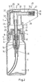
- Fig. 2 shows a modified embodiment in which the same elements with the same reference numerals as in Fig. 1 are provided. Has changed the protective cap 20.
- the protective cap 20 has distributed in the circumferential direction a plurality of radially inwardly projecting webs 31 which are connected to the side wall 25 and the top wall 26 and preferably designed in one piece therewith.
- the webs 31 are on a side facing away from the receiving opening 5 side of the first portion 21 of the housing 4 with a contact area 32.
- a contact area 32 is, as I said, on the front side of the first portion 21 of the housing 4.
- the other contact area is on the increase in diameter 23 of the housing 4, as in the embodiment according to Fig. 1 also.
- a total of five webs 31 are provided.
- the webs 31 are, as I said, from the side wall 25 radially inwardly.
- the webs 31 have in the radial and circumferential direction a thickness which is greater than the thickness of the side wall 25 in the radial direction. In many cases, however, it will be sufficient if the webs 31 have a greater thickness than the radial thickness of the side wall 25 only in the circumferential direction or only in the radial direction.
- the webs 31 have two tasks. They serve for a power transmission from the top wall 26 to the housing 4. On the other hand, they also stiff the side wall 25, so that the side wall 25 can transmit greater forces.
- the side wall 25 has an interruption 33 which extends from the top wall 26 to the end of the protective cap 20 facing the housing 4. This makes it possible to put the cap 20 despite the presence of the projection 17 on the pump 1.
- Two webs 31a, 31b are arranged adjacent to the interruption 33. Your distance from the break 33 is smaller than its thickness in the circumferential direction. Accordingly, the side wall 25 is here stiffened immediately adjacent to the interruption 33, so that here too a sufficient power transmission is possible.
Landscapes
- Containers And Packaging Bodies Having A Special Means To Remove Contents (AREA)
- Closures For Containers (AREA)
Description
- Die Erfindung betrifft eine Pumpe, insbesondere eine Rachenspray-Pumpe, mit einem Gehäuse, das eine Aufnahmeöffnung mit einer Aufprellgeometrie aufweist, einem Betätigungselement, das auf der der Aufnahmeöffnung abgewandten Seite des Gehäuses angeordnet ist und bei einer Betätigung in einer Betätigungsrichtung in das Gehäuse verlagerbar ist, und einer Ausgabedüse, die an einem quer zur Betätigungsrichtung vorstehenden Vorsprung angeordnet ist.
- Eine derartige Pumpe ist beispielsweise aus
DE 102 00 595 A1 bekannt. - Mit einer derartigen Pumpe soll ein Produkt gezielt an eine bestimmte Stelle gesprüht werden können. Wenn es sich bei dem Produkt um ein Medikament handelt, das beispielsweise in den Rachen eines Menschen gesprüht werden soll, dann dient der Vorsprung dazu, die Ausgabedüse möglichst nahe an die zu behandelnde Stelle zu bringen. Wenn der Bediener dann das Betätigungselement betätigt, wird eine dosierte Menge des Produkts ausgegeben.
- Insbesondere bei Medikamenten ist es von einer gewissen Bedeutung, dass diese vor einer Kontaminierung geschützt werden. Man muss daher das Behältnis, in dem das Medikament aufgenommen ist und aus dem das Medikament mit Hilfe der Pumpe entnommen werden soll, geschlossen halten. Aus diesem Grund wird das Gehäuse der Pumpe auf das Behältnis, beispielsweise eine Glas- oder Kunststoffflasche, aufgeprellt. Dadurch wird das Gehäuse so mit dem Behältnis verbunden, dass das Behältnis jedenfalls für den normalen Bediener nicht mehr geöffnet werden kann.
- Zum Aufprellen wird die Pumpe mit der Aufnahmeöffnung des Gehäuses auf das Behältnis aufgesetzt. Man muss dann eine teilweise erhebliche Kraft auf die Pumpe aufbringen, um die Aufprellgeometrie über eine entsprechende Gegengeometrie am Behältnis hinweg zu bewegen. Die hierzu notwendigen Kräfte liegen durchaus bei mehreren Hundert Newton.
- Man hat die zum Aufprellen notwendige Kraft bislang über das Betätigungselement eingeleitet. Dies hat mehrere Nachteile. Zum einen kann das Betätigungselement und damit die Pumpe beim Aufprellen beschädigt werden. Zum anderen ist es schwierig, die zum Aufprellen notwendige Kraft genau zu dosieren, da das Betätigungselement in der Regel gegen eine Feder arbeitet.
-
US 2009/0152303 A1 zeigt eine weitere Pumpe mit einem Gehäuse, das eine Aufnahmeöffnung mit einer Rastgeometrie aufweist, einem Betätigungselement, das auf der der Aufnahmeöffnung abgewandten Seite des Gehäuses angeordnet ist und bei Betätigung in einer Betätigungsrichtung in das Gehäuse verlagerbar ist, und einer Ausgabedüse, die quer zur Betätigungsrichtung ausgerichtet ist. Ferner ist eine Schutzkappe auf einen Befestigungsring aufgesetzt, der das Gehäuse umgibt. Die Schutzkappe weist eine von der Aufnahmeöffnung abgewandte Deckelwand auf, die mit einer Seitenwand verbunden ist, die zumindest teilweise auf einer Flächenanordnung am Befestigungsring aufsteht, die senkrecht zur Betätigungsrichtung verläuft. Zum Aufsetzen der Pumpe auf einen Behälter wird die mit der Schutzkappe versehene Pumpe auf den Behälter aufgesetzt, so dass die Vorsprünge der Rastgeometrie hinter einen umlaufenden Vorsprung am Behälter einrasten können. Danach wird mit Hilfe der Schutzkappe der Verriegelungsring auf den Behälter hin verschoben, so dass die Schürze, die die Rastgeometrie trägt, nicht mehr nach außen ausfedern kann und somit die Pumpe fest auf dem Behälter gehalten ist. - Der Erfindung liegt die Aufgabe zugrunde, die Montage der Pumpe an einem Behälter ohne Beeinträchtigung der Pumpe durchführen zu können.
- Diese Aufgabe wird bei einer Pumpe der eingangs genannten Art dadurch gelöst, dass eine Schutzkappe auf das Gehäuse aufgesetzt ist, die eine von der Aufnahmeöffnung abgewandte Deckelwand aufweist, die mit einer Seitenwand verbunden ist, die zumindest teilweise auf einer Flächenanordnung am Gehäuse aufsteht, die senkrecht zur Betätigungsrichtung verläuft, wobei die Seitenwand im Bereich des Vorsprungs eine Unterbrechung in Umfangsrichtung aufweist, die bis zu einem dem Gehäuse zugewandten Ende der Seitenwand reicht, und die Schutzkappe zur Übertragung von Aufprellkräften dimensioniert ist.
- Mit einer derartigen Schutzkappe ist es möglich, das Gehäuse auf den Behälter aufzuprellen, ohne die Pumpe im Übrigen zu belasten. Die zum Aufprellen notwendigen Kräfte werden über die Schutzkappe und deren Seitenwand unmittelbar an das Gehäuse übertragen. Bestandteile der Pumpe werden beim Aufprellen nicht mit Kräften beaufschlagt, so dass das Risiko einer Beschädigung nahezu ausgeschlossen ist. Die Kräfte, die man zum Aufprellen benötigt, können relativ genau dimensioniert werden, so dass die Pumpe auch zuverlässig auf dem Behälter sitzt und der Behälter nicht beschädigt wird. Darüber hinaus kann man nun bei der Pumpe eine Originalitätssicherung in Verbindung mit dem Betätigungselement einbauen, so dass ein Benutzer erkennen kann, ob der mit der Pumpe versehene Behälter schon einmal verwendet worden ist oder nicht. Aufgrund der Unterbrechung kann die Schutzkappe trotz des Vorsprungs auf das Gehäuse der Pumpe aufgesetzt werden, um die zum Aufprellen notwendigen Kräfte einzuleiten.
- Vorzugsweise liegt die Seitenwand an der Umfangswand des Gehäuses mit einer Vorspannung an. Man kann dann die Schutzkappe auch nach der Montage der Pumpe am Gehäuse am Gehäuse der Pumpe belassen. Die Schutzkappe dient also nicht nur zur Montage der Pumpe am Behälter, sondern übernimmt auch weitere schützende Funktionen, beispielsweise beim Transport des Behälters.
- Vorzugsweise weist die Umfangswand zumindest in einem Abschnitt, in dem die Seitenwand an ihr anliegt, die Form einer Zylindermantelfläche auf. Dies macht es relativ leicht, die gewünschte Vorspannung zu erzeugen.
- Es ist bevorzugt, dass die Seitenwand das Gehäuse über mindestens 185°, vorzugsweise über mindestens 210° und besonders bevorzugt über mindestens 240° in Umfangsrichtung umschließt. In allen Fällen ist sichergestellt, dass man die zum Aufprellen notwendige Kraft über die Schutzkappe auf das Gehäuse aufbringen kann, ohne dass sich Schiefstellungen oder dergleichen ergeben. Gleichwohl ist genügend Platz vorhanden, um den Vorsprung durch die Seitenwand hindurch ragen zu lassen.
- Bevorzugterweise weist die Deckelwand eine die Unterbrechung überdeckende Verlängerung auf, die den Vorsprung überdeckt. Damit wird auch der Vorsprung durch die Schutzkappe geschützt und zwar sowohl während des Aufprellens des Gehäuses auf den Behälter als auch während eines Transports des Behälters.
- Hierbei ist bevorzugt, dass die Verlängerung mit einer abgewinkelten Stirnseite versehen ist, die die Ausgabedüse abdeckt. Dadurch wird das Risiko klein gehalten, dass Schmutz von außen in den Bereich der Düse gelangt. Natürlich kann man dies nicht völlig ausschließen. Durch die Abdeckung wird aber beispielsweise die direkte Beaufschlagung der Düse mit Schmutz verhindert, wenn die Schutzkappe aufgesteckt ist.
- Vorzugsweise ist die Stirnseite über Verbindungswände mit der Seitenwand verbunden. Dies ergibt eine erhöhte Stabilität der Schutzkappe, was sich sowohl beim Aufprellen der Pumpe auf den Behälter als auch beim späteren Transport positiv bemerkbar macht.
- Bevorzugterweise weist die Seitenwand mindestens zwei Aufstandsbereiche auf, die in unterschiedlichen Entfernungen von der Ausgabeöffnung am Gehäuse anliegen. Die Aufstandsbereiche haben gegebenenfalls auch unterschiedliche Positionen in radialer Richtung. Damit wird die für die Kraftübertragung auf das Gehäuse zur Verfügung stehende Fläche vergrößert. Je größer die Fläche ist, desto kleiner ist bei ansonsten unveränderten Bedingungen die über die Schutzkappe einzuleitende Druckspannung. Dies hält die Belastung der Kappe klein.
- Vorzugsweise liegt ein erster Aufstandsbereich an einer Ringwand an, die das Betätigungselement umgibt, und ein zweiter Aufstandsbereich liegt an einer Durchmesservergrößerung der Ringwand an. Diese Durchmesservergrößerung kann beispielsweise einen Übergang von einem ersten Gehäuseabschnitt, in dem das Betätigungselement angeordnet ist, zu einem zweiten Gehäuseabschnitt bilden, in dem die Aufnahmeöffnung ausgebildet ist. Damit wird die zum Aufprellen notwendige Kraft in solche Gehäuseteile eingeleitet, die diese Kraft auch ohne Weiteres aufnehmen können. Das Aufprellen kann daher mit einer hohen Zuverlässigkeit erfolgen.
- Vorzugsweise weist der erste Aufstandsbereich mehrere in Umfangsrichtung verteilte radial nach innen weisende Stege auf. Beispielsweise können in Umfangsrichtung verteilt fünf Stege vorgesehen sein. Die Stege übertragen nicht nur die zum Aufprellen des Gehäuses notwendige Kraft auf das Gehäuse, sondern sie steifen auch die Seitenwand aus, so dass die Seitenwand selbst auch größere Kräfte übertragen kann.
- Hierbei ist bevorzugt, dass die Stege in Umfangsrichtung und/oder in Radialrichtung eine Dicke aufweisen, die größer ist als die Dicke der Seitenwand in Radialrichtung. Damit lässt sich die Schutzkappe insgesamt mit einer relativ kleinen Masse ausbilden, weil die Seitenwand relativ dünn gehalten werden kann. Dies spart zum einen Kosten und erleichtert zum anderen die Handhabung.
- Vorzugsweise weist mindestens ein Steg zur Unterbrechung einen Abstand auf, der kleiner ist als die Dicke des Stegs in Umfangsrichtung. Damit ist also ein Steg der Unterbrechung unmittelbar benachbart, so dass die Seitenwand direkt neben der Unterbrechung eine verbesserte Steifigkeit aufweist und auch hier entsprechende Kräfte übertragen kann. Vorzugsweise sind sogar an beiden Seiten der Unterbrechung entsprechende Stege angeordnet.
- Vorzugsweise sind die Stege mit der Deckelwand verbunden. Es ergibt sich damit eine unmittelbare Krafteinleitung über die Deckelwand an die Stege, so dass hier ausreichend große Kräfte übertragen werden können.
- Auch ist von Vorteil, wenn die Stege radial außen am Betätigungselement anliegen. Dadurch wird die Schutzkappe noch besser am Gehäuse geführt. Eine Beeinträchtigung der Pumpe ist damit nicht verbunden, weil keine in Betätigungsrichtung wirkenden Kräfte auf das Betätigungselement wirken. Die Schutzkappe hält aber nach der Montage der Pumpe am Behälter besser auf dem Gehäuse fest.
- Die Erfindung wird im Folgenden anhand von bevorzugten Ausführungsbeispielen in Verbindung mit einer Zeichnung beschrieben. Hierin zeigen:
- Fig. 1
- eine auf einen Behälter aufgesetzte Pumpe mit einer Schutzkappe einer ersten Ausführungsform,
- Fig. 2
- die Ansicht nach
Fig. 1 mit einer Schutzkappe nach einer zweiten Ausführungsform, - Fig. 3
- die Schutzkappe nach
Fig. 2 von unten, - Fig. 4
- die Schutzkappe nach
Fig. 3 von vorne, - Fig. 5
- einen Schritt V-V nach
Fig. 3 und - Fig. 6
- die Schutzkappe in perspektivischer Darstellung.
- Eine in
Fig. 1 dargestellte Pumpe 1, die als Rachenspray-Pumpe ausgebildet ist, ist auf einen Behälter 2 aufgeprellt. Der Behälter 2 ist beispielsweise als Flasche aus Glas oder Kunststoff ausgebildet und weist einen Vorratsraum 3 auf, in dem (nicht dargestellt) ein Medikament zur Behandlung von Beschwerden in einem Rachen eines Menschen angeordnet ist. - Die Pumpe 1 weist ein Gehäuse 4 mit einer Aufnahmeöffnung 5 auf, in die ein Hals 6 des Behälters 2 eingesetzt ist. Um das Gehäuse 4 an dem Hals festzuhalten, ist die Aufnahmeöffnung 5 mit einer Aufprellgeometrie 7 versehen, beispielsweise einem umlaufenden radial nach innen vorstehenden Vorsprung. Der Hals 6 ist mit einem entsprechenden Gegenvorsprung 8 versehen. Um das Gehäuse 4 auf dem Behälter 2 zu befestigen, muss das Gehäuse 4 mit der Aufnahmeöffnung 5 zunächst auf den Hals 6 aufgesetzt werden. Danach muss man eine Kraft auf das Gehäuse in Richtung des Behälters 2 ausüben, die so groß ist, dass sich das Gehäuse 4 zumindest in dem Bereich, wo die Aufprellgeometrie 7 angeordnet ist, so weit aufweitet, dass die Aufprellgeometrie 7 über den Gegenvorsprung 8 hinweg gleiten kann. Aufgrund der Elastizität des Gehäuses 4 rastet dann die Aufprellgeometrie 7 hinter dem Gegenvorsprung 8 ein. Die für diese Art der Befestigung notwendigen Kräfte, die auch als "Aufprellkräfte" bezeichnet werden, liegen durchaus im Bereich von mehreren Hundert N. Im vorliegenden Fall liegen die Aufprellkräfte in der Größenordnung von 400 N.
- Die Pumpe 1 weist ein Betätigungselement 9 auf, das gegen die Kraft einer Feder 10 bei einer Betätigung in eine Betätigungsrichtung (Pfeil 18) in das Gehäuse 4 hinein verlagerbar ist. Das Betätigungselement 9 ist hierbei durch eine Herausfallsicherung 11 im Gehäuse 4 gehalten. Bei der Betätigung verkleinert das Betätigungselement 9 mit einem Stößel 12 einen Pumpenraum 13, der zwischen dem Stößel 12 und einem Hilfsgehäuse 14 ausgebildet ist. Der Pumpenraum 13 ist durch ein Rückschlagventil mit einem Ventilelement 15 zum Vorratsraum 3 hin abgeschlossen. Wenn der Pumpenraum 13 verkleinert wird, dann wird eine darin befindliche Flüssigkeit durch eine Düse 16 ausgestoßen, die an einem Vorsprung 17 ausgebildet ist, der sich quer zu einer Betätigungsrichtung 18 erstreckt. Die Düse 16 ist mit dem Pumpenraum 13 über Kanäle 19 verbunden. Wenn das Betätigungselement 9 losgelassen wird, dann wird es durch die Kraft der Feder 10 wieder nach außen gedrückt, so dass sich der Pumpenraum 13 vergrößert und dabei über das Rückschlagventil mit dem Ventilelement 15 Flüssigkeit aus dem Vorratsraum 3 ansaugt.
- Die Funktion einer derartigen Pumpe ist an sich bekannt und in der eingangs erwähnten
DE 102 00 595 A1 beschrieben. - Die zum Aufprellen des Gehäuses 4 auf dem Behälter 2 notwendigen Kräfte wurden bislang über das Betätigungselement 9 eingebracht. Dies hat sich als ungünstig erwiesen.
- Um diese Kräfte, die in Betätigungsrichtung 18 wirken müssen, in das Gehäuse 4 einleiten zu können, ist nunmehr eine Schutzkappe 20 vorgesehen, die auf das Gehäuse 4 aufgesetzt ist. Das Gehäuse 4 weist einen zylinderförmigen ersten Abschnitt 21 auf, in dem das Betätigungselement 9 angeordnet ist, und einen ebenfalls zylinderförmig ausgebildeten zweiten Abschnitt 22, in dem die Aufnahmeöffnung 5 ausgebildet ist. Zwischen den beiden Abschnitten 21, 22 ist eine Durchmesservergrößerung 23 ausgebildet. Die Durchmesservergrößerung 23 bildet hier auf der der Schutzkappe 20 zugewandten Seite eine Flächenanordnung 24, auf der die Schutzkappe 20 mit einer Seitenwand 25 aufsteht. Die Seitenwand 25 der Schutzkappe 20 wiederum ist verbunden mit einer Deckelwand 26. Wenn man in Betätigungsrichtung 18 eine Kraft auf die Deckelwand 26 aufbringt, dann wird diese Kraft über die Seitenwand 25 in das Gehäuse 24 eingeleitet. Die Seitenwand 25 ist dabei so dimensioniert, dass sie die erforderlichen Aufprellkräfte übertragen kann. Sie muss also eine gewisse Steifigkeit aufweisen, um ein Ausbeulen zu verhindern. Die Größe der Aufprellkräfte richtet sich nach verschiedenen Kriterien, beispielsweise die Ausbildung der Aufprellgeometrie oder die Größe der Pumpe. Die Aufprellkräfte lassen sich aber leicht ermitteln und entsprechend kann man dann die Schutzkappe 20 dimensionieren.
- Die Seitenwand 25 liegt an der Umfangswand des ersten Abschnitts 21 mit einer gewissen Vorspannung an, d.h. man benötigt auch eine kleine Kraft, um die Schutzkappe 20 vom Gehäuse 4 abziehen zu können. Die Schutzkappe 20 kann dann auch als Schutz während eines Transports oder zwischen zwei Handhabungen der Pumpe 1 dienen.
- Die Deckelwand 26 weist eine Verlängerung 27 auf, die den Vorsprung 17 überdeckt. Die Verlängerung 27 weist eine nach unten abgewinkelte Stirnseite 28 auf, die die Düse 16 abdeckt. Die Stirnseite 28 ist mit der Seitenwand 25 über Verbindungswände 29 (nur eine dargestellt) mit der Seitenwand 25 verbunden.
- Von der Seitenwand 25 ist ein Abschnitt 30 erkennbar, der um den ersten Abschnitt 21 des Gehäuses 4 herum geführt ist. Die Seitenwand ist dabei nicht über den vollen Umfang des ersten Abschnitts 21 des Gehäuses 4 geführt, sondern weist eine Unterbrechung auf, durch die der Vorsprung 17 geführt ist. Diese Unterbrechung wird im Zusammenhang mit einem zweiten Ausführungsbeispiel der Schutzkappe in Verbindung mit den
Fig. 3 bis 6 beschrieben. - Die Seitenwand 25 erstreckt sich auf jeden Fall mindestens über 185° des Gehäuses 4 in Umfangsrichtung. Bevorzugterweise erstreckt sich die Seitenwand 25 über mindestens 210° oder sogar über mindestens 240° in Umfangsrichtung. Dies stellt sicher, dass die Seitenwand in der Lage ist, die zum Aufprellen des Gehäuses 4 auf den Behälter 2 notwendigen Kräfte auch in Umfangsrichtung in ausreichendem Maße verteilt zu übertragen.
-
Fig. 2 zeigt ein abgewandeltes Ausführungsbeispiel, bei dem gleiche Elemente mit den gleichen Bezugszeichen wie inFig. 1 versehen sind. Geändert hat sich die Schutzkappe 20. - Die Schutzkappe 20 weist in Umfangsrichtung verteilt mehrere radial nach innen ragende Stege 31 auf, die mit der Seitenwand 25 und der Deckelwand 26 verbunden und vorzugsweise einstückig damit ausgeführt sind. Die Stege 31 stehen mit einem Aufstandsbereich 32 auf einer der Aufnahmeöffnung 5 abgewandten Seite des ersten Abschnitts 21 des Gehäuses 4 auf. Damit weist die Schutzkappe 20 nun zwei Aufstandsbereiche auf, die in unterschiedlichen Entfernungen von der Ausgabeöffnung 5 am Gehäuse 4 anliegen. Ein Aufstandsbereich 32 steht, wie gesagt, auf der Stirnseite des ersten Abschnitts 21 des Gehäuses 4 auf. Der andere Aufstandsbereich steht auf der Durchmesservergrößerung 23 des Gehäuses 4 auf, wie bei der Ausführungsform nach
Fig. 1 auch. - Wie aus
Fig. 3 ersichtlich, sind insgesamt fünf Stege 31 vorgesehen. Die Stege 31 stehen, wie gesagt, von der Seitenwand 25 radial nach innen. Die Stege 31 haben in radialer und in Umfangsrichtung eine Dicke, die größer ist als die Dicke der Seitenwand 25 in radialer Richtung. In vielen Fällen wird es aber ausreichen, wenn die Stege 31 nur in Umfangsrichtung oder nur in radialer Richtung eine größere Dicke als die radiale Dicke der Seitenwand 25 aufweisen. Die Stege 31 haben zwei Aufgaben. Sie dienen zum einen zur Kraftübertragung von der Deckelwand 26 auf das Gehäuse 4. Zum anderen steifen sie auch die Seitenwand 25 aus, so dass die Seitenwand 25 größere Kräfte übertragen kann. - Wie oben erwähnt, weist die Seitenwand 25 eine Unterbrechung 33 auf, die sich von der Deckelwand 26 bis zu dem dem Gehäuse 4 zugewandten Ende der Schutzkappe 20 erstreckt. Damit ist es möglich, die Schutzkappe 20 trotz Vorhandensein des Vorsprungs 17 auf die Pumpe 1 aufzusetzen.
- Zwei Stege 31a, 31b sind der Unterbrechung 33 benachbart angeordnet. Ihr Abstand von der Unterbrechung 33 ist kleiner als ihre Dicke in Umfangsrichtung. Dementsprechend wird die Seitenwand 25 hier unmittelbar neben der Unterbrechung 33 ausgesteift, so dass auch hier eine ausreichende Kraftübertragung möglich ist.
- Wie insbesondere noch in
Fig. 2 zu erkennen ist, liegen die Stege 31 radial von außen am Betätigungselement an oder sie haben nur ein kleines Spiel zum Betätigungselement 9. Dadurch wird das Betätigungselement 9 bei einem Transport der Pumpe 1 stabilisiert.
Claims (14)
- Pumpe, insbesondere Rachenspray-Pumpe mit einem Gehäuse (4), das eine Aufnahmeöffnung (5) mit einer Aufprellgeometrie (6) aufweist, einem Betätigungselement (9), das auf der der Aufnahmeöffnung (5) abgewandten Seite des Gehäuses (4) angeordnet ist und bei Betätigung in einer Betätigungsrichtung (18) in das Gehäuse (4) verlagerbar ist, und einer Ausgabedüse (16), die an einem quer zur Betätigungsrichtung (18) vorstehenden Vorsprung (17) angeordnet ist, dadurch gekennzeichnet, dass eine Schutzkappe (20) auf das Gehäuse (4) aufgesetzt ist, die eine von der Aufnahmeöffnung (5) abgewandte Deckelwand (26) aufweist, die mit einer Seitenwand (25) verbunden ist, die zumindest teilweise auf einer Flächenanordnung (24, 32) am Gehäuse (4) aufsteht, die senkrecht zur Betätigungsrichtung (18) verläuft, wobei die Seitenwand (25) im Bereich des Vorsprungs (17) eine Unterbrechung (33) aufweist, die bis zu einem dem Gehäuse (4) zugewandten Ende der Seitenwand (25) reicht, und die Schutzkappe (20) zur Übertragung von Aufprellkräften dimensioniert ist.
- Pumpe nach Anspruch 1, dadurch gekennzeichnet, dass die Seitenwand (25) an einer Umfangswand des Gehäuses (4) mit einer Vorspannung anliegt.
- Pumpe nach Anspruch 2, dadurch gekennzeichnet, dass die Umfangswand zumindest in einem Abschnitt (21), in dem die Seitenwand (25) an ihr anliegt, die Form einer Zylindermantelfläche aufweist.
- Pumpe nach einem der Ansprüche 1 bis 3, dadurch gekennzeichnet, dass die Seitenwand (25) das Gehäuse (4) über mindestens 185°, vorzugsweise über mindestens 210° und besonders bevorzugt über mindestens 240° in Umfangsrichtung umschließt.
- Pumpe nach einem der Ansprüche 1 bis 4, dadurch gekennzeichnet, dass die Deckelwand (26) eine die Unterbrechung (33) überdeckende Verlängerung (27) aufweist, die den Vorsprung (17) überdeckt.
- Pumpe nach Anspruch 5, dadurch gekennzeichnet, dass die Verlängerung (27) mit einer abgewinkelten Stirnseite (28) versehen ist, die die Ausgabedüse (16) abdeckt.
- Pumpe nach Anspruch 6, dadurch gekennzeichnet, dass die Stirnseite (28) über Verbindungswände (29) mit der Seitenwand (25) verbunden ist.
- Pumpe nach einem der Ansprüche 1 bis 7, dadurch gekennzeichnet, dass die Seitenwand (25) mindestens zwei Aufstandsbereiche aufweist, die in unterschiedlichen Entfernungen von der Aufnahmeöffnung (5) am Gehäuse (4) anliegen.
- Pumpe nach Anspruch 8, dadurch gekennzeichnet, dass ein erster Aufstandsbereich an einer Ringwand anliegt, die das Betätigungselement (9) umgibt, und ein zweiter Aufstandsbereich an einer Durchmesservergrößerung der Ringwand anliegt.
- Pumpe nach Anspruch 9, dadurch gekennzeichnet, dass der erste Aufstandsbereich mehrere in Umfangsrichtung verteilte radial nach innen weisende Stege (31) aufweist.
- Pumpe nach Anspruch 10, dadurch gekennzeichnet, dass die Stege in Umfangsrichtung und/oder in Radialrichtung eine Dicke aufweisen, die größer ist als die Dicke der Seitenwand (25) in Radialrichtung.
- Pumpe nach Anspruch 10 oder 11, dadurch gekennzeichnet, dass mindestens ein Steg (31a, 31b) zur Unterbrechung (33) einen Abstand aufweist, der kleiner ist als die Dicke des Stegs (31a, 31b) in Umfangsrichtung.
- Pumpe nach einem der Ansprüche 10 bis 12, dadurch gekennzeichnet, dass die Stege (31) mit der Deckelwand (26) verbunden sind.
- Pumpe nach einem der Ansprüche 10 bis 13, dadurch gekennzeichnet, dass die Stege (31) radial außen am Betätigungselement (9) anliegen.
Applications Claiming Priority (1)
| Application Number | Priority Date | Filing Date | Title |
|---|---|---|---|
| DE102010022161A DE102010022161B4 (de) | 2010-05-20 | 2010-05-20 | Pumpe, insbesondere Rachenspray-Pumpe |
Publications (2)
| Publication Number | Publication Date |
|---|---|
| EP2388075A1 EP2388075A1 (de) | 2011-11-23 |
| EP2388075B1 true EP2388075B1 (de) | 2015-12-02 |
Family
ID=44523055
Family Applications (1)
| Application Number | Title | Priority Date | Filing Date |
|---|---|---|---|
| EP11003396.6A Revoked EP2388075B1 (de) | 2010-05-20 | 2011-04-21 | Pumpe, insbesondere Rachenspray-Pumpe |
Country Status (3)
| Country | Link |
|---|---|
| EP (1) | EP2388075B1 (de) |
| DE (1) | DE102010022161B4 (de) |
| ES (1) | ES2557320T3 (de) |
Cited By (1)
| Publication number | Priority date | Publication date | Assignee | Title |
|---|---|---|---|---|
| CN106110453A (zh) * | 2016-08-31 | 2016-11-16 | 广州润虹医药科技有限公司 | 盐水鼻腔喷雾器 |
Families Citing this family (3)
| Publication number | Priority date | Publication date | Assignee | Title |
|---|---|---|---|---|
| FR2974792B1 (fr) * | 2011-05-05 | 2013-06-21 | Airlessystems | Distributeur de produit fluide. |
| EP2796206B1 (de) | 2013-04-26 | 2016-12-21 | Aptar Radolfzell GmbH | Austragkopf für einen Behälter und Verfahren zur Befestigung eines Austragkopfs an einem Behälter |
| BE1023939B1 (fr) * | 2016-07-13 | 2017-09-15 | Laboratoire Puressentiel S.A. | Pulvérisateur à étanchéité élevée |
Citations (6)
| Publication number | Priority date | Publication date | Assignee | Title |
|---|---|---|---|---|
| JPS59123568U (ja) | 1983-02-09 | 1984-08-20 | 株式会社吉野工業所 | 液体吐出容器 |
| US20020195167A1 (en) | 2001-06-14 | 2002-12-26 | Valois S.A.S. | Fluid dispenser |
| DE10200595A1 (de) | 2002-01-10 | 2003-07-31 | Aero Pump Gmbh | Betätigungskopf einer Saug-Druck-Pumpe zum Ausspritzen eines Produkts aus einem Behältnis |
| US20080179272A1 (en) | 2007-01-30 | 2008-07-31 | Pierre Gardet | Bottle Comprising a Neck Connected to a Body |
| DE102007056380A1 (de) | 2007-11-22 | 2009-06-04 | Meadwestvaco Calmar Gmbh | Verschlusskappe für einen Austragkopf |
| US20090152303A1 (en) | 2007-12-12 | 2009-06-18 | Valois Sas | Fluid dispenser |
Family Cites Families (1)
| Publication number | Priority date | Publication date | Assignee | Title |
|---|---|---|---|---|
| FR2891529B1 (fr) * | 2005-10-04 | 2007-12-07 | Valois Sas | Organe de recouvrement, procede de fabrication d'un tel organe et distributeur comprenant un tel organe. |
-
2010
- 2010-05-20 DE DE102010022161A patent/DE102010022161B4/de not_active Revoked
-
2011
- 2011-04-21 ES ES11003396.6T patent/ES2557320T3/es active Active
- 2011-04-21 EP EP11003396.6A patent/EP2388075B1/de not_active Revoked
Patent Citations (6)
| Publication number | Priority date | Publication date | Assignee | Title |
|---|---|---|---|---|
| JPS59123568U (ja) | 1983-02-09 | 1984-08-20 | 株式会社吉野工業所 | 液体吐出容器 |
| US20020195167A1 (en) | 2001-06-14 | 2002-12-26 | Valois S.A.S. | Fluid dispenser |
| DE10200595A1 (de) | 2002-01-10 | 2003-07-31 | Aero Pump Gmbh | Betätigungskopf einer Saug-Druck-Pumpe zum Ausspritzen eines Produkts aus einem Behältnis |
| US20080179272A1 (en) | 2007-01-30 | 2008-07-31 | Pierre Gardet | Bottle Comprising a Neck Connected to a Body |
| DE102007056380A1 (de) | 2007-11-22 | 2009-06-04 | Meadwestvaco Calmar Gmbh | Verschlusskappe für einen Austragkopf |
| US20090152303A1 (en) | 2007-12-12 | 2009-06-18 | Valois Sas | Fluid dispenser |
Cited By (2)
| Publication number | Priority date | Publication date | Assignee | Title |
|---|---|---|---|---|
| CN106110453A (zh) * | 2016-08-31 | 2016-11-16 | 广州润虹医药科技有限公司 | 盐水鼻腔喷雾器 |
| CN106110453B (zh) * | 2016-08-31 | 2018-03-06 | 广州润虹医药科技股份有限公司 | 盐水鼻腔喷雾器 |
Also Published As
| Publication number | Publication date |
|---|---|
| DE102010022161B4 (de) | 2013-02-21 |
| DE102010022161A1 (de) | 2011-11-24 |
| ES2557320T3 (es) | 2016-01-25 |
| EP2388075A1 (de) | 2011-11-23 |
Similar Documents
| Publication | Publication Date | Title |
|---|---|---|
| DE102007056380B4 (de) | Verschlusskappe für einen Austragkopf | |
| DE69607260T2 (de) | Befestigungsring mit Doppelindexiervorrichtung | |
| EP3978389B1 (de) | Flüssigkeitsspender, insbesondere tropfenspender | |
| DE2216343C3 (de) | ||
| EP1852390B1 (de) | Absperrorgan für einen Behälter, insbesondere Palettenbehälter | |
| WO2014139832A1 (de) | Aufsatz für eine spritze, karpule oder dergleichen | |
| WO2010040366A1 (de) | Verschluss zum aufschrauben auf einen behälter | |
| WO2014072440A1 (de) | Spritzenverschluss | |
| WO1995027568A1 (de) | Austragvorrichtung für fliessfähige medien, insbesondere für den austrag in nur einem hub | |
| DE102007054673B4 (de) | Bandschmiereinrichtung und/oder Reinigungs-Desinfektionsanlage | |
| EP4166239B1 (de) | Quetschflaschenspender mit betätigungssicherung | |
| EP3048081B1 (de) | Ventilblockanordnung für ein flaschenaufsatzgerät | |
| EP2388075A1 (de) | Pumpe, insbesondere Rachenspray-Pumpe | |
| EP1919539A1 (de) | Griffleiste für eine spritze mit verbessertem berstschutz | |
| EP0151225B1 (de) | Schutz- und Originalitätssicherungskappe für eine handbetätigte Austragsvorrichtung | |
| CH705378B1 (de) | Kabelverschraubung. | |
| EP0269068B1 (de) | Aerosol-Verpackung | |
| WO2007118613A1 (de) | Flüssigkeitsbehälter | |
| DE3337060A1 (de) | Verschlusskappe fuer einen sicherheitsbehaelter | |
| DE102015210309B4 (de) | Betätigungselement mit einem Knopf | |
| EP1963193A1 (de) | Universelle verschlussvorrichtung | |
| DE4204977C2 (de) | Kindersicherheitsverschluß | |
| EP0484714A1 (de) | Austragvorrichtung für Medien | |
| DE102017119644B4 (de) | Geberzylinder für ein Kupplungs- oder Bremssystem mit Dichtelement | |
| AT401085B (de) | Verschlussanordnung |
Legal Events
| Date | Code | Title | Description |
|---|---|---|---|
| AK | Designated contracting states |
Kind code of ref document: A1 Designated state(s): AL AT BE BG CH CY CZ DE DK EE ES FI FR GB GR HR HU IE IS IT LI LT LU LV MC MK MT NL NO PL PT RO RS SE SI SK SM TR |
|
| AX | Request for extension of the european patent |
Extension state: BA ME |
|
| PUAI | Public reference made under article 153(3) epc to a published international application that has entered the european phase |
Free format text: ORIGINAL CODE: 0009012 |
|
| 17P | Request for examination filed |
Effective date: 20111229 |
|
| RIC1 | Information provided on ipc code assigned before grant |
Ipc: B05B 11/00 20060101AFI20150527BHEP Ipc: B65D 83/14 20060101ALI20150527BHEP |
|
| GRAP | Despatch of communication of intention to grant a patent |
Free format text: ORIGINAL CODE: EPIDOSNIGR1 |
|
| INTG | Intention to grant announced |
Effective date: 20150731 |
|
| GRAS | Grant fee paid |
Free format text: ORIGINAL CODE: EPIDOSNIGR3 |
|
| GRAA | (expected) grant |
Free format text: ORIGINAL CODE: 0009210 |
|
| AK | Designated contracting states |
Kind code of ref document: B1 Designated state(s): AL AT BE BG CH CY CZ DE DK EE ES FI FR GB GR HR HU IE IS IT LI LT LU LV MC MK MT NL NO PL PT RO RS SE SI SK SM TR |
|
| REG | Reference to a national code |
Ref country code: GB Ref legal event code: FG4D Free format text: NOT ENGLISH |
|
| REG | Reference to a national code |
Ref country code: AT Ref legal event code: REF Ref document number: 763382 Country of ref document: AT Kind code of ref document: T Effective date: 20151215 Ref country code: CH Ref legal event code: EP |
|
| REG | Reference to a national code |
Ref country code: IE Ref legal event code: FG4D Free format text: LANGUAGE OF EP DOCUMENT: GERMAN |
|
| REG | Reference to a national code |
Ref country code: DE Ref legal event code: R096 Ref document number: 502011008443 Country of ref document: DE |
|
| REG | Reference to a national code |
Ref country code: ES Ref legal event code: FG2A Ref document number: 2557320 Country of ref document: ES Kind code of ref document: T3 Effective date: 20160125 |
|
| REG | Reference to a national code |
Ref country code: SE Ref legal event code: TRGR |
|
| REG | Reference to a national code |
Ref country code: NL Ref legal event code: MP Effective date: 20160302 |
|
| REG | Reference to a national code |
Ref country code: LT Ref legal event code: MG4D |
|
| REG | Reference to a national code |
Ref country code: FR Ref legal event code: PLFP Year of fee payment: 6 |
|
| PG25 | Lapsed in a contracting state [announced via postgrant information from national office to epo] |
Ref country code: NO Free format text: LAPSE BECAUSE OF FAILURE TO SUBMIT A TRANSLATION OF THE DESCRIPTION OR TO PAY THE FEE WITHIN THE PRESCRIBED TIME-LIMIT Effective date: 20160302 Ref country code: LT Free format text: LAPSE BECAUSE OF FAILURE TO SUBMIT A TRANSLATION OF THE DESCRIPTION OR TO PAY THE FEE WITHIN THE PRESCRIBED TIME-LIMIT Effective date: 20151202 |
|
| PG25 | Lapsed in a contracting state [announced via postgrant information from national office to epo] |
Ref country code: NL Free format text: LAPSE BECAUSE OF FAILURE TO SUBMIT A TRANSLATION OF THE DESCRIPTION OR TO PAY THE FEE WITHIN THE PRESCRIBED TIME-LIMIT Effective date: 20151202 Ref country code: RS Free format text: LAPSE BECAUSE OF FAILURE TO SUBMIT A TRANSLATION OF THE DESCRIPTION OR TO PAY THE FEE WITHIN THE PRESCRIBED TIME-LIMIT Effective date: 20151202 Ref country code: GR Free format text: LAPSE BECAUSE OF FAILURE TO SUBMIT A TRANSLATION OF THE DESCRIPTION OR TO PAY THE FEE WITHIN THE PRESCRIBED TIME-LIMIT Effective date: 20160303 Ref country code: LV Free format text: LAPSE BECAUSE OF FAILURE TO SUBMIT A TRANSLATION OF THE DESCRIPTION OR TO PAY THE FEE WITHIN THE PRESCRIBED TIME-LIMIT Effective date: 20151202 Ref country code: PL Free format text: LAPSE BECAUSE OF FAILURE TO SUBMIT A TRANSLATION OF THE DESCRIPTION OR TO PAY THE FEE WITHIN THE PRESCRIBED TIME-LIMIT Effective date: 20151202 Ref country code: FI Free format text: LAPSE BECAUSE OF FAILURE TO SUBMIT A TRANSLATION OF THE DESCRIPTION OR TO PAY THE FEE WITHIN THE PRESCRIBED TIME-LIMIT Effective date: 20151202 |
|
| PG25 | Lapsed in a contracting state [announced via postgrant information from national office to epo] |
Ref country code: CZ Free format text: LAPSE BECAUSE OF FAILURE TO SUBMIT A TRANSLATION OF THE DESCRIPTION OR TO PAY THE FEE WITHIN THE PRESCRIBED TIME-LIMIT Effective date: 20151202 |
|
| PGFP | Annual fee paid to national office [announced via postgrant information from national office to epo] |
Ref country code: DE Payment date: 20160414 Year of fee payment: 6 Ref country code: ES Payment date: 20160422 Year of fee payment: 6 Ref country code: GB Payment date: 20160422 Year of fee payment: 6 |
|
| REG | Reference to a national code |
Ref country code: DE Ref legal event code: R026 Ref document number: 502011008443 Country of ref document: DE |
|
| PG25 | Lapsed in a contracting state [announced via postgrant information from national office to epo] |
Ref country code: RO Free format text: LAPSE BECAUSE OF FAILURE TO SUBMIT A TRANSLATION OF THE DESCRIPTION OR TO PAY THE FEE WITHIN THE PRESCRIBED TIME-LIMIT Effective date: 20151202 Ref country code: SM Free format text: LAPSE BECAUSE OF FAILURE TO SUBMIT A TRANSLATION OF THE DESCRIPTION OR TO PAY THE FEE WITHIN THE PRESCRIBED TIME-LIMIT Effective date: 20151202 Ref country code: SK Free format text: LAPSE BECAUSE OF FAILURE TO SUBMIT A TRANSLATION OF THE DESCRIPTION OR TO PAY THE FEE WITHIN THE PRESCRIBED TIME-LIMIT Effective date: 20151202 Ref country code: IS Free format text: LAPSE BECAUSE OF FAILURE TO SUBMIT A TRANSLATION OF THE DESCRIPTION OR TO PAY THE FEE WITHIN THE PRESCRIBED TIME-LIMIT Effective date: 20160402 Ref country code: PT Free format text: LAPSE BECAUSE OF FAILURE TO SUBMIT A TRANSLATION OF THE DESCRIPTION OR TO PAY THE FEE WITHIN THE PRESCRIBED TIME-LIMIT Effective date: 20160404 Ref country code: EE Free format text: LAPSE BECAUSE OF FAILURE TO SUBMIT A TRANSLATION OF THE DESCRIPTION OR TO PAY THE FEE WITHIN THE PRESCRIBED TIME-LIMIT Effective date: 20151202 Ref country code: BE Free format text: LAPSE BECAUSE OF NON-PAYMENT OF DUE FEES Effective date: 20160430 |
|
| PGFP | Annual fee paid to national office [announced via postgrant information from national office to epo] |
Ref country code: FR Payment date: 20160422 Year of fee payment: 6 Ref country code: SE Payment date: 20160422 Year of fee payment: 6 Ref country code: IT Payment date: 20160422 Year of fee payment: 6 |
|
| PLBI | Opposition filed |
Free format text: ORIGINAL CODE: 0009260 |
|
| 26 | Opposition filed |
Opponent name: APTAR RADOLFZELL GMBH Effective date: 20160826 |
|
| PLAX | Notice of opposition and request to file observation + time limit sent |
Free format text: ORIGINAL CODE: EPIDOSNOBS2 |
|
| PG25 | Lapsed in a contracting state [announced via postgrant information from national office to epo] |
Ref country code: DK Free format text: LAPSE BECAUSE OF FAILURE TO SUBMIT A TRANSLATION OF THE DESCRIPTION OR TO PAY THE FEE WITHIN THE PRESCRIBED TIME-LIMIT Effective date: 20151202 |
|
| PG25 | Lapsed in a contracting state [announced via postgrant information from national office to epo] |
Ref country code: SI Free format text: LAPSE BECAUSE OF FAILURE TO SUBMIT A TRANSLATION OF THE DESCRIPTION OR TO PAY THE FEE WITHIN THE PRESCRIBED TIME-LIMIT Effective date: 20151202 |
|
| REG | Reference to a national code |
Ref country code: CH Ref legal event code: PL |
|
| PG25 | Lapsed in a contracting state [announced via postgrant information from national office to epo] |
Ref country code: LU Free format text: LAPSE BECAUSE OF FAILURE TO SUBMIT A TRANSLATION OF THE DESCRIPTION OR TO PAY THE FEE WITHIN THE PRESCRIBED TIME-LIMIT Effective date: 20160421 |
|
| REG | Reference to a national code |
Ref country code: IE Ref legal event code: MM4A |
|
| PG25 | Lapsed in a contracting state [announced via postgrant information from national office to epo] |
Ref country code: CH Free format text: LAPSE BECAUSE OF NON-PAYMENT OF DUE FEES Effective date: 20160430 Ref country code: LI Free format text: LAPSE BECAUSE OF NON-PAYMENT OF DUE FEES Effective date: 20160430 |
|
| PLBB | Reply of patent proprietor to notice(s) of opposition received |
Free format text: ORIGINAL CODE: EPIDOSNOBS3 |
|
| PG25 | Lapsed in a contracting state [announced via postgrant information from national office to epo] |
Ref country code: IE Free format text: LAPSE BECAUSE OF NON-PAYMENT OF DUE FEES Effective date: 20160421 |
|
| REG | Reference to a national code |
Ref country code: AT Ref legal event code: MM01 Ref document number: 763382 Country of ref document: AT Kind code of ref document: T Effective date: 20160421 |
|
| PG25 | Lapsed in a contracting state [announced via postgrant information from national office to epo] |
Ref country code: AT Free format text: LAPSE BECAUSE OF NON-PAYMENT OF DUE FEES Effective date: 20160421 |
|
| REG | Reference to a national code |
Ref country code: DE Ref legal event code: R119 Ref document number: 502011008443 Country of ref document: DE |
|
| GBPC | Gb: european patent ceased through non-payment of renewal fee |
Effective date: 20170421 |
|
| REG | Reference to a national code |
Ref country code: FR Ref legal event code: ST Effective date: 20171229 |
|
| PG25 | Lapsed in a contracting state [announced via postgrant information from national office to epo] |
Ref country code: FR Free format text: LAPSE BECAUSE OF NON-PAYMENT OF DUE FEES Effective date: 20170502 Ref country code: DE Free format text: LAPSE BECAUSE OF NON-PAYMENT OF DUE FEES Effective date: 20171103 |
|
| PG25 | Lapsed in a contracting state [announced via postgrant information from national office to epo] |
Ref country code: SE Free format text: LAPSE BECAUSE OF NON-PAYMENT OF DUE FEES Effective date: 20170422 Ref country code: GB Free format text: LAPSE BECAUSE OF NON-PAYMENT OF DUE FEES Effective date: 20170421 |
|
| RDAF | Communication despatched that patent is revoked |
Free format text: ORIGINAL CODE: EPIDOSNREV1 |
|
| STAA | Information on the status of an ep patent application or granted ep patent |
Free format text: STATUS: THE PATENT HAS BEEN GRANTED |
|
| REG | Reference to a national code |
Ref country code: DE Ref legal event code: R064 Ref document number: 502011008443 Country of ref document: DE Ref country code: DE Ref legal event code: R103 Ref document number: 502011008443 Country of ref document: DE |
|
| PG25 | Lapsed in a contracting state [announced via postgrant information from national office to epo] |
Ref country code: HU Free format text: LAPSE BECAUSE OF FAILURE TO SUBMIT A TRANSLATION OF THE DESCRIPTION OR TO PAY THE FEE WITHIN THE PRESCRIBED TIME-LIMIT; INVALID AB INITIO Effective date: 20110421 Ref country code: CY Free format text: LAPSE BECAUSE OF FAILURE TO SUBMIT A TRANSLATION OF THE DESCRIPTION OR TO PAY THE FEE WITHIN THE PRESCRIBED TIME-LIMIT Effective date: 20151202 Ref country code: IT Free format text: LAPSE BECAUSE OF NON-PAYMENT OF DUE FEES Effective date: 20170421 |
|
| PG25 | Lapsed in a contracting state [announced via postgrant information from national office to epo] |
Ref country code: MK Free format text: LAPSE BECAUSE OF FAILURE TO SUBMIT A TRANSLATION OF THE DESCRIPTION OR TO PAY THE FEE WITHIN THE PRESCRIBED TIME-LIMIT Effective date: 20151202 Ref country code: TR Free format text: LAPSE BECAUSE OF FAILURE TO SUBMIT A TRANSLATION OF THE DESCRIPTION OR TO PAY THE FEE WITHIN THE PRESCRIBED TIME-LIMIT Effective date: 20151202 Ref country code: MT Free format text: LAPSE BECAUSE OF FAILURE TO SUBMIT A TRANSLATION OF THE DESCRIPTION OR TO PAY THE FEE WITHIN THE PRESCRIBED TIME-LIMIT Effective date: 20151202 Ref country code: HR Free format text: LAPSE BECAUSE OF FAILURE TO SUBMIT A TRANSLATION OF THE DESCRIPTION OR TO PAY THE FEE WITHIN THE PRESCRIBED TIME-LIMIT Effective date: 20151202 Ref country code: MC Free format text: LAPSE BECAUSE OF FAILURE TO SUBMIT A TRANSLATION OF THE DESCRIPTION OR TO PAY THE FEE WITHIN THE PRESCRIBED TIME-LIMIT Effective date: 20151202 |
|
| REG | Reference to a national code |
Ref country code: ES Ref legal event code: FD2A Effective date: 20180629 |
|
| PG25 | Lapsed in a contracting state [announced via postgrant information from national office to epo] |
Ref country code: ES Free format text: LAPSE BECAUSE OF NON-PAYMENT OF DUE FEES Effective date: 20170422 Ref country code: BG Free format text: LAPSE BECAUSE OF FAILURE TO SUBMIT A TRANSLATION OF THE DESCRIPTION OR TO PAY THE FEE WITHIN THE PRESCRIBED TIME-LIMIT Effective date: 20151202 |
|
| RDAG | Patent revoked |
Free format text: ORIGINAL CODE: 0009271 |
|
| STAA | Information on the status of an ep patent application or granted ep patent |
Free format text: STATUS: PATENT REVOKED |
|
| 27W | Patent revoked |
Effective date: 20180506 |
|
| PG25 | Lapsed in a contracting state [announced via postgrant information from national office to epo] |
Ref country code: AL Free format text: LAPSE BECAUSE OF FAILURE TO SUBMIT A TRANSLATION OF THE DESCRIPTION OR TO PAY THE FEE WITHIN THE PRESCRIBED TIME-LIMIT Effective date: 20151202 |
|
| REG | Reference to a national code |
Ref country code: BE Ref legal event code: MM Effective date: 20160430 |
|
| REG | Reference to a national code |
Ref country code: AT Ref legal event code: MA03 Ref document number: 763382 Country of ref document: AT Kind code of ref document: T Effective date: 20180506 |
|
| REG | Reference to a national code |
Ref country code: SE Ref legal event code: ECNC |