EP2387929A1 - Electric vacuum cleaner - Google Patents
Electric vacuum cleaner Download PDFInfo
- Publication number
- EP2387929A1 EP2387929A1 EP09835075A EP09835075A EP2387929A1 EP 2387929 A1 EP2387929 A1 EP 2387929A1 EP 09835075 A EP09835075 A EP 09835075A EP 09835075 A EP09835075 A EP 09835075A EP 2387929 A1 EP2387929 A1 EP 2387929A1
- Authority
- EP
- European Patent Office
- Prior art keywords
- spark
- value
- electric blower
- vacuum cleaner
- electric
- Prior art date
- Legal status (The legal status is an assumption and is not a legal conclusion. Google has not performed a legal analysis and makes no representation as to the accuracy of the status listed.)
- Granted
Links
- 238000001514 detection method Methods 0.000 claims abstract description 87
- OKTJSMMVPCPJKN-UHFFFAOYSA-N Carbon Chemical compound [C] OKTJSMMVPCPJKN-UHFFFAOYSA-N 0.000 claims abstract description 27
- 229910052799 carbon Inorganic materials 0.000 claims abstract description 27
- 239000000428 dust Substances 0.000 claims abstract description 17
- 230000004913 activation Effects 0.000 claims description 13
- 238000005070 sampling Methods 0.000 claims description 12
- 230000007420 reactivation Effects 0.000 claims 1
- 230000000391 smoking effect Effects 0.000 abstract description 20
- 238000000034 method Methods 0.000 description 11
- 230000008569 process Effects 0.000 description 8
- 238000007796 conventional method Methods 0.000 description 5
- 238000010586 diagram Methods 0.000 description 5
- 230000007246 mechanism Effects 0.000 description 5
- 238000002474 experimental method Methods 0.000 description 3
- 230000007257 malfunction Effects 0.000 description 2
- 230000008859 change Effects 0.000 description 1
- 230000005484 gravity Effects 0.000 description 1
- 238000005259 measurement Methods 0.000 description 1
- 230000002093 peripheral effect Effects 0.000 description 1
- 230000004044 response Effects 0.000 description 1
- 238000000926 separation method Methods 0.000 description 1
Images






Classifications
-
- A—HUMAN NECESSITIES
- A47—FURNITURE; DOMESTIC ARTICLES OR APPLIANCES; COFFEE MILLS; SPICE MILLS; SUCTION CLEANERS IN GENERAL
- A47L—DOMESTIC WASHING OR CLEANING; SUCTION CLEANERS IN GENERAL
- A47L9/00—Details or accessories of suction cleaners, e.g. mechanical means for controlling the suction or for effecting pulsating action; Storing devices specially adapted to suction cleaners or parts thereof; Carrying-vehicles specially adapted for suction cleaners
- A47L9/28—Installation of the electric equipment, e.g. adaptation or attachment to the suction cleaner; Controlling suction cleaners by electric means
- A47L9/2889—Safety or protection devices or systems, e.g. for prevention of motor over-heating or for protection of the user
-
- A—HUMAN NECESSITIES
- A47—FURNITURE; DOMESTIC ARTICLES OR APPLIANCES; COFFEE MILLS; SPICE MILLS; SUCTION CLEANERS IN GENERAL
- A47L—DOMESTIC WASHING OR CLEANING; SUCTION CLEANERS IN GENERAL
- A47L9/00—Details or accessories of suction cleaners, e.g. mechanical means for controlling the suction or for effecting pulsating action; Storing devices specially adapted to suction cleaners or parts thereof; Carrying-vehicles specially adapted for suction cleaners
- A47L9/28—Installation of the electric equipment, e.g. adaptation or attachment to the suction cleaner; Controlling suction cleaners by electric means
- A47L9/2805—Parameters or conditions being sensed
-
- A—HUMAN NECESSITIES
- A47—FURNITURE; DOMESTIC ARTICLES OR APPLIANCES; COFFEE MILLS; SPICE MILLS; SUCTION CLEANERS IN GENERAL
- A47L—DOMESTIC WASHING OR CLEANING; SUCTION CLEANERS IN GENERAL
- A47L9/00—Details or accessories of suction cleaners, e.g. mechanical means for controlling the suction or for effecting pulsating action; Storing devices specially adapted to suction cleaners or parts thereof; Carrying-vehicles specially adapted for suction cleaners
- A47L9/28—Installation of the electric equipment, e.g. adaptation or attachment to the suction cleaner; Controlling suction cleaners by electric means
- A47L9/2805—Parameters or conditions being sensed
- A47L9/281—Parameters or conditions being sensed the amount or condition of incoming dirt or dust
-
- A—HUMAN NECESSITIES
- A47—FURNITURE; DOMESTIC ARTICLES OR APPLIANCES; COFFEE MILLS; SPICE MILLS; SUCTION CLEANERS IN GENERAL
- A47L—DOMESTIC WASHING OR CLEANING; SUCTION CLEANERS IN GENERAL
- A47L9/00—Details or accessories of suction cleaners, e.g. mechanical means for controlling the suction or for effecting pulsating action; Storing devices specially adapted to suction cleaners or parts thereof; Carrying-vehicles specially adapted for suction cleaners
- A47L9/28—Installation of the electric equipment, e.g. adaptation or attachment to the suction cleaner; Controlling suction cleaners by electric means
- A47L9/2805—Parameters or conditions being sensed
- A47L9/2831—Motor parameters, e.g. motor load or speed
-
- A—HUMAN NECESSITIES
- A47—FURNITURE; DOMESTIC ARTICLES OR APPLIANCES; COFFEE MILLS; SPICE MILLS; SUCTION CLEANERS IN GENERAL
- A47L—DOMESTIC WASHING OR CLEANING; SUCTION CLEANERS IN GENERAL
- A47L9/00—Details or accessories of suction cleaners, e.g. mechanical means for controlling the suction or for effecting pulsating action; Storing devices specially adapted to suction cleaners or parts thereof; Carrying-vehicles specially adapted for suction cleaners
- A47L9/28—Installation of the electric equipment, e.g. adaptation or attachment to the suction cleaner; Controlling suction cleaners by electric means
- A47L9/2836—Installation of the electric equipment, e.g. adaptation or attachment to the suction cleaner; Controlling suction cleaners by electric means characterised by the parts which are controlled
- A47L9/2842—Suction motors or blowers
-
- A—HUMAN NECESSITIES
- A47—FURNITURE; DOMESTIC ARTICLES OR APPLIANCES; COFFEE MILLS; SPICE MILLS; SUCTION CLEANERS IN GENERAL
- A47L—DOMESTIC WASHING OR CLEANING; SUCTION CLEANERS IN GENERAL
- A47L9/00—Details or accessories of suction cleaners, e.g. mechanical means for controlling the suction or for effecting pulsating action; Storing devices specially adapted to suction cleaners or parts thereof; Carrying-vehicles specially adapted for suction cleaners
- A47L9/28—Installation of the electric equipment, e.g. adaptation or attachment to the suction cleaner; Controlling suction cleaners by electric means
- A47L9/2868—Arrangements for power supply of vacuum cleaners or the accessories thereof
- A47L9/2878—Dual-powered vacuum cleaners, i.e. devices which can be operated with mains power supply or by batteries
Definitions
- the present invention relates to an electric vacuum cleaner having a spark detector which detects a spark caused by the friction between a commutator and a carbon brush of an electric blower.
- the electric vacuum cleaner according to Patent Document 1 uses a spark detector which obtains most recent data and previous data of the digital values sampled by an A/D converter, and determines a spark failure when the calculated difference value is greater than a preset predetermined spark determination level. Further, the spark detector calculates a difference between a maximum value and a minimum value within a predetermined period of time, and determines a spark failure when the calculated difference value is greater than a preset predetermined spark determination level.
- the electric vacuum cleaner according to Patent Document 2 has a light detector which detects a spark caused by the friction between a commutator and a carbon brush of an electric blower. In response to detection of a spark by the light detector, an electric blower error is detected to stop the electric blower.
- the electric vacuum cleaner according to Patent Document 1 obtains most recent data and previous data of the digital values sampled by an A/D converter, and determines a spark failure when the calculated difference value is greater than a preset predetermined spark determination level. In this case, if the preset predetermined spark determination level is incorrect or does not contain a tolerance, a misdetection may occur. Further, the electric vacuum cleaner calculates a difference between a maximum value and a minimum value within a predetermined period of time, and determines a spark failure when the calculated difference value is greater than a preset predetermined spark determination level. In this case, noise may be detected leading to misdetection, which may deteriorate reliability.
- the electric vacuum cleaner according to Patent Document 1 does not consider subsequent control after an error is detected and the electric blower is stopped, and is not easy to use.
- the electric vacuum cleaner according to Patent Document 1 obtains most recent data and previous data of the digital values sampled by an A/D converter, and determines a spark failure when the calculated difference value is greater than a preset predetermined spark determination level.
- a preset predetermined spark determination level In general, when the electric blower is activated, the rate of spark occurrence is high and then the rate tends to be lowered.
- the spark detector and the electric blower lack control considering this trend. Further, if the predetermined value is just one, and is set based on sparks occurring when some period of time has elapsed and the electric blower is operating stably, a high rate of spark occurrence at the time of activation may exceed the predetermined value and the normally operating electric blower may be inconveniently stopped.
- the light detector of the electric vacuum cleaner according to Patent Document 2 in a case where sparks producing a large amount of light are reduced over time lacks stability and reliability in light detection.
- An object of the present invention is to provide an electric vacuum cleaner which detects a spark caused by the friction between a commutator and a carbon brush of an electric blower and stops the operation of the electric blower to prevent smoking and ignition from occurring in the electric blower.
- Another object of the present invention is to provide an electric vacuum cleaner which is free from misdetection to ensure reliable and stable error detection; not only detects a spark caused by the friction between a commutator and a carbon brush of an electric blower and stops the operation of the electric blower but also after the operation is stopped, activates a control apparatus to control the electric blower to prevent smoking and ignition from occurring in the electric blower; and is ease of use.
- Still another object of the present invention is to provide an electric vacuum cleaner which without stopping the normally operating electric blower, detects a spark caused by the friction between a commutator and a carbon brush of the electric blower and stops the operation of the electric blower to prevent smoking and ignition from occurring in the electric blower; and is excellent in reliability.
- an electric vacuum cleaner comprises: a dust collecting chamber disposed in a vacuum cleaner body; an electric blower which causes a suction negative pressure to act on the dust collecting chamber; a spark detector which detects a spark caused by friction between a commutator and a carbon brush of the electric blower; and a control unit which controls the electric blower based on spark detection information from the spark detector, wherein the spark detector calculates a difference between a previous value and a most recent value of sampled values; estimates a next value from the difference; and when an absolute value of the difference between an estimated value and a measured value is greater than a predetermined value, the control unit stops operation of the electric blower.
- the spark detector calculates a difference between a previous value and a most recent value of the sampled values; estimates a next value from the difference; and determines that a spark occurs when the difference between an estimated value and a measured value is greater than a predetermined value.
- the control unit stops the operation of the electric blower and after the stop, does not reactivate the electric blower.
- the control unit stops the operation of the electric blower and enables the operation of the electric blower until the number of stops reaches a predetermined number of times.
- a plurality of the predetermined values is set. During a period from the activation of the electric blower up to within a predetermined time, a first predetermined value is set and after the predetermined time has elapsed, a predetermined value lower than the first predetermined value is set.
- the electric vacuum cleaner 1 comprises: a vacuum cleaner body 2; a dust collection hose 3 one end of which is connected in an attachable and detachable manner to a horse connection port 2a formed in a front portion of the vacuum cleaner body 2; an extension tube 5 which is connected in an attachable and detachable manner to a hand operating pipe 4 disposed in the other end of the dust collection hose 3; and a floor suction fitting 6 which is connected in an attachable and detachable manner to a front end of the extension tube 5.
- the inside of the vacuum cleaner body 2 includes a first dust separator and a second dust separator, both of which are communicatively connected to the dust collection hose 3 and are not illustrated.
- the vacuum cleaner body 2 includes a dust collecting chamber 7 having a dust collector adopting a high-speed separation system which separates dust contained in air flowing at high speeds by gravity difference as the first dust separator; and having a pleat filter as the second dust separator; and an electric blower 10 which causes a suction negative pressure to act on the dust collecting chamber 7.
- the electric blower 10 includes a centrifugal blower section 12 having a suction port 11; and a motor section 14 having an exhaust port 13.
- the motor section 14 includes a motor housing 15 having an exhaust port 13; a stator 16 disposed on an inner peripheral surface 15a of the motor housing 15; a rotor 17 rotatably supported inside the motor housing 15; and a pair of brush mechanisms 18 disposed in the motor housing 15 and electrically connected to the rotor 17.
- the stator 16, the rotor 17, and a pair of brush mechanisms 18 constitute a motor 20.
- the rotor 17 is disposed inside the stator 16.
- the rotor 17 includes a rotor shaft 21 disposed at the shaft center; a field coil 22 (rotor coil) wound around the rotor shaft 21; and a commutator 23 electrically connected to the field coil 22 and disposed on the rotor shaft 21.
- the brush mechanism 18 includes a brush holder 25 penetrated through a brush holder fixing section 24; a carbon brush 26 slidably housed in the brush holder 25; and a coil spring 27 which presses and urges the carbon brush 26 to the commutator 23 of the rotor 17.
- a control circuit 30 for an electric blower includes the electric blower 20, a spark detector 31, a control unit 32, a power regulation section 33, and power supply voltage detector 34.
- a current transformer which detects a current of the electric blower 20 is used.
- the current detected by the current transformer is converted to a voltage value.
- the power supply for example, a commercial power supply of rated 100 V is used.
- the control unit 32 includes a microcomputer and a memory.
- a microcomputer for example, a triac is used.
- the spark detector 31 detects a current flowing through the electric blower 20. Based on the spark detection information, the control circuit 30 controls the electric blower 20 through the control unit 32 and the power regulation section 33.
- the power supply voltage detector 34 detects a power supply voltage, and inputs the power supply voltage information to the control unit 32.
- the electric vacuum cleaner 1 is used and the electric blower 10 is turned on (S1).
- a plurality of samplings is performed at equal time intervals. Samplings are performed, for example, at a half-frequency of 50 Hz at a sampling interval of 10 ms at 100 points. When phase control is performed, the samplings are performed only when current flows.
- the spark detector 31 detects a current flowing through the electric blower 10 and converts the current to a voltage (S2).
- the voltage value is stored in the control unit 32 as a previously measured value Ia of the sampling (n-2) (S3).
- the spark detector 31 detects a current flowing through the electric blower 10, converts the current to a voltage, and stores the voltage value in the control unit 32 as the most recently measured value Ib of the sampling (n-1) (S4).
- the control unit 32 calculates an estimated value Ine (S5).
- the estimated value Ine is estimated from a previously measured value Ia and a most recently measured value Ib, and more specifically, a difference between the previously measured value Ia and the most recently measured value Ib is added to the most recently measured value Ib.
- the control unit 32 determines whether or not the absolute value of a difference between the estimated value Ine and the measured value In is greater than the predetermined value Is (S6).
- control unit 32 determines whether
- the current value in the sampling n is used as the measured value In.
- the predetermined value Is is calculated by experiment in advance in a state in which the carbon brush 26 is normal.
- the control circuit 30 stops the electric blower 10 through the control unit 32 and the power regulation section 33 (S7).
- the state in which the absolute value of the difference between the estimated value Ine and the measured value In is greater than the predetermined value Is indicates that a spark occurs by the friction between the commutator 23 and the carbon brush 26 in the electric blower 10.
- the control circuit 30 stops the electric blower 10 to prevent smoking and ignition from occurring in the electric blower 10.
- the state in which the absolute value of the difference between the estimated value Ine and the measured value In is not greater than the predetermined value Is indicates that a spark does not occurs by the friction between the commutator 23 and the carbon brush 26 in the electric blower 10.
- the control circuit 30 allows the electric blower 10 to continue operating.
- the first example of the present spark detection and control determines whether or not a spark occurs in such a manner that the difference between a previous value and a most recent value of the sampled measured values is obtained to estimate a next value; and when the absolute value of the difference between the estimated value and the next measured value is greater than the predetermined value, the operation of the electric blower is stopped.
- the first example of the present spark detection and control detects a spark caused by the friction between the commutator and the carbon brush, safely stops the operation of the electric blower, and prevents smoking and ignition from occurring in the electric blower.
- the detection steps are repeated a plurality of n-2 times and the control unit 32 determines whether or not the integrated absolute value of the difference between the measured value In 1 and the estimated value Ine 1 is greater than the predetermined value Is (S16).
- control unit 32 determines whether
- the control circuit 30 stops the electric blower 10 through the control unit 32 and the power regulation section 33 (S17).
- the second example of the present spark detection and control determines whether or not a spark occurs in such a manner that the detection steps are repeated a plurality of n-2 times; and the absolute value of the difference between the measured value and the estimated value is integrated, allowing the measured value and the estimated value to be unvarying and stable.
- the second example of the present spark detection and control detects a spark caused by the friction between the commutator and the carbon brush, safely stops the operation of the electric blower, and prevents smoking and ignition from occurring in the electric blower.
- the detection steps are repeated a plurality of n-2 times to integrate the absolute value of the difference between the measured value In 2 and the estimated value Ine 2 , and the integrated value is stored.
- the detection steps are repeated a plurality of n-2 times in the same phase, and further in a cycle (S+Nn), the detection steps are repeated a plurality of (S+Nn) times.
- the integrated values of the obtained absolute value of the difference between the measured value In 2 and the estimated value Ine 2 are averaged for each frequency of the power supply (n times) to determine whether or not the averaged value is greater than the predetermined value Is (S26).
- the third example of the present spark detection and control determines whether or not a spark occurs in such a manner that in a plurality of cycles, the detection steps are repeated a plurality of times; and the integrated values of the absolute value of the difference between the measured value In2 and the estimated value Ine 2 are averaged for each frequency of the power supply (n times), allowing exceptional values to be removed and the unvarying and stable integrated values to be used.
- the third example of the present spark detection and control detects a spark caused by the friction between the commutator and the carbon brush, safely stops the operation of the electric blower, and prevents smoking and ignition from occurring in the electric blower.
- the fourth example of the present spark detection and control changes the predetermined value according to the power supply voltage value in the first to third examples.
- the integrated values vary depending on the strong mode and the middle mode in 50 Hz.
- the predetermined value needs to be changed according to the change in power supply voltage and the frequency.
- the power supply voltage detector 34 illustrated in Fig. 3 detects a power supply voltage and the power supply voltage information is inputted to the control unit 32 which rewrites a predetermined value preliminarily stored in the memory.
- the relation between the power supply voltage (detection voltage) and the predetermined value is as illustrated in Fig. 14 .
- the predetermined value is determined for each classification of power supply voltage.
- the predetermined value is A for the voltage ⁇ 80V; the predetermined value is B for 80 V ⁇ the voltage ⁇ 90 V; the predetermined value is C for 90 V ⁇ the voltage ⁇ 100 V; and the predetermined value is D for 100 V ⁇ the voltage.
- the predetermined value is rewritten for each 10 V.
- the fourth example of the present spark detection and control determines whether or not a spark occurs in such a manner that in addition to the detection steps in the first to third examples of the spark detection and control, the predetermined value is changed according to the power supply voltage value.
- the fourth example of the present spark detection and control accurately detects a spark caused by the friction between the commutator and the carbon brush, safely stops the operation of the electric blower, and prevents smoking and ignition from occurring in the electric blower.
- the electric vacuum cleaner according to the first embodiment of the present invention detects a spark caused by the friction between the commutator and the carbon brush of the electric blower, stops the operation of the electric blower, and prevents smoking and ignition from occurring in the electric blower.
- the electric vacuum cleaner according to the second embodiment not only has the same configuration as that of the electric vacuum cleaner according to the first embodiment but also has a notification unit 35 connected to the control unit 32 as illustrated in Fig. 15 .
- the steps S31 to S36 in the flowchart of the second example of the present spark detection and control illustrated in Fig. 16 are the same as the steps S1 to S6 in the first example of the electric vacuum cleaner according to the first embodiment illustrated in Fig. 4 , and thus the description will be omitted.
- the control unit 32 stops the electric blower 10 to prevent smoking and ignition from occurring in the electric blower 10.
- the notification unit 35 notifies that a spark occurs and the electric blower 10 stops (S37).
- the stop information of the electric blower 10 is stored in a memory of the control unit 32 (S38).
- the memory when the memory is unplugged to stop supplying power to the electric vacuum cleaner 1, the memory holds the stop information therein; and when the power plug is inserted again to supply power to the electric vacuum cleaner 1, an operation request from a control switch 4a will be ignored to prevent the electric blower 10 from operating.
- the first example of the spark detection and control determines whether or not a spark occurs in such a manner that the difference between a previous value and a most recent value of sampled measured values is obtained to estimate a next value; and when the difference between the estimated value and the next measured value is greater than the predetermined value, the operation of the electric blower is stopped. Additionally, after the operation is stopped, a control apparatus is activated to store the stop information in the memory, and a subsequent operation request from outside such as a control switch is ignored to prevent the electric blower from operating and to prevent smoking and ignition from occurring in the electric blower.
- the second example of the present spark detection and control stops the subsequent operation of the electric blower when and after the number of operation stops reaches a predetermined times.
- the steps S41 to S46 are the same as the steps S1 to S6 in the first example of the electric vacuum cleaner according to the first embodiment illustrated in Fig. 4 , and thus the description will be omitted.
- the control unit 32 determines whether or not the number of stops reaches a predetermined number of times (S49).
- the memory of the control unit 32 stores the number of stops (S50).
- This state is the same state in which the stop button is pressed.
- the second example of the present spark detection and control when the number of stops does not reach a predetermined number of times, the operation of the electric blower is resumed. When a spark occurs, the operation momentarily stops, but the operation is resumed.
- the second example improves convenience and prevents smoking and ignition from occurring in the electric blower.
- the third example of the present spark detection and control erases the number of operation stops stored in the memory when normal operation is determined.
- the third example of the present spark detection and control detects a spark in the same manner as in the steps S1 to S6 of the first example of the first embodiment illustrated in Fig. 4 .
- the third example of the present spark detection and control when the electric blower returns to normal, the count is cleared; and when a spark occurs, the operation momentarily stops, but the operation is resumed.
- the third example improves convenience and prevents smoking and ignition from occurring in the electric blower.
- the electric vacuum cleaner according to the second embodiment of the present invention is free from misdetection to ensure reliable and stable error detection; not only detects a spark caused by the friction between the commutator and the carbon brush of the electric blower and stops the operation of the electric blower but also after the operation is stopped, activates a control apparatus to control the electric blower to prevent smoking and ignition from occurring in the electric blower; and is ease of use.
- the electric vacuum cleaner according to the third embodiment has the same configuration as that of the electric vacuum cleaner according to the first embodiment.
- the electric vacuum cleaner 1 is used and the electric blower 10 is activated (S71).
- the spark detection is performed in the same manner as in the steps S1 to S6 of the first example of the first embodiment illustrated in Fig. 4 .
- the control unit 32 stores the absolute value of the difference between the estimated value Ine and the measured value In in a storage unit of the control unit 32 as a detection value (spark amount) based on the spark detection information.
- control unit 32 After the electric blower 10 is activated, the control unit 32 detects whether the predetermined time has elapsed or not (S73).
- Fig. 20 is a correlation graph between an operating time and a spark amount after the electric blower is activated. As illustrated in Fig. 20 , the predetermined time is set to, for example, two minutes when the spark amount becomes stable two minutes after the activation.
- predetermined value is determined by experiment as follows.
- the time from when the electric blower is activated to when the spark amount becomes stable and the spark amount are measured.
- the measurements are confirmed on a plurality of electric blowers. From these experiments, the highest spark amount at activation, the time taken until the spark amount becomes stable, and the spark amount are obtained and multiplied by a safety factor to set the predetermined value.
- the first predetermined value is obtained by multiplying a maximum detection value illustrated in Fig. 20 by a safety factor (for example, 1.1) for preventing malfunction.
- a safety factor for example, 1.1
- the control unit 32 stops the operation of the electric blower 10 (S75).
- the control unit 32 stops the operation of the electric blower 10 to prevent smoking and ignition from occurring in the electric blower 10.
- the second predetermined value is obtained by multiplying a stable value illustrated in Fig. 20 by a safety factor (for example, 1.4) for preventing malfunction.
- a safety factor for example, 1.4
- the control unit 32 stops the operation of the electric blower 10 (S75).
- the control unit 32 stops the operation of the electric blower 10 to prevent smoking and ignition from occurring in the electric blower 10.
- the state in which a determination is made in S74 and S76 that the detection value is not equal to or greater than the first and second predetermined values respectively indicates that a spark does not occurs by the friction between the commutator 23 and the carbon brush 26 in the electric blower 10.
- the control circuit 30 allows the electric blower 10 to continue operating.
- Fig. 20 is a correlation graph between an operating time and a spark amount after activation of an electric blower, where the first setting value and the second setting value are determined for each classification of power supply voltage as illustrated in Fig. 21 .
- the first setting value is C1
- the second setting value is C2.
- These setting values may be changed for each classification of the power supply voltage as described above, for each operating mode of the electric blower as described in the first embodiment, for each frequency of the power supply, or a combination thereof.
- the third embodiment specifies two setting values: a first setting value and a second setting value lower than the first setting value, but the setting values may further include a third setting value lower than the second setting value, and further may include a plurality of setting values.
- the power supply is not limited to an AC power supply, but may be a cordless charging system.
- the electric blower is subject to control such as stop; and after the predetermined time has elapsed, when the detection value is greater than the second predetermined value lower than the first predetermined value, the electric blower is subject to control such as stop.
- the present electric vacuum cleaner of the third embodiment does not stop the normally operating electric blower, detects a spark caused by the friction between a commutator and a carbon brush in the electric blower, and stops the operation of the electric blower to prevent smoking and ignition from occurring in the electric blower.
- the present electric vacuum cleaner of the third embodiment does not stop the normally operating electric blower, detects a spark caused by the friction between a commutator and a carbon brush in the electric blower, and stops the operation of the electric blower to prevent smoking and ignition from occurring in the electric blower, thereby achieving a reliable electric vacuum cleaner.
Landscapes
- Engineering & Computer Science (AREA)
- Mechanical Engineering (AREA)
- Electric Vacuum Cleaner (AREA)
Abstract
Description
- The present invention relates to an electric vacuum cleaner having a spark detector which detects a spark caused by the friction between a commutator and a carbon brush of an electric blower.
- There has been conventionally proposed an electric vacuum cleaner in which in order to prevent smoking and ignition from occurring in an electric blower, a spark caused by the friction between a commutator and a carbon brush of the electric blower is detected by a spark detector to control the electric blower (for example, see
Patent Documents 1 and 2). - The electric vacuum cleaner according to
Patent Document 1 uses a spark detector which obtains most recent data and previous data of the digital values sampled by an A/D converter, and determines a spark failure when the calculated difference value is greater than a preset predetermined spark determination level. Further, the spark detector calculates a difference between a maximum value and a minimum value within a predetermined period of time, and determines a spark failure when the calculated difference value is greater than a preset predetermined spark determination level. - Further, the electric vacuum cleaner according to
Patent Document 2 has a light detector which detects a spark caused by the friction between a commutator and a carbon brush of an electric blower. In response to detection of a spark by the light detector, an electric blower error is detected to stop the electric blower. - However, the electric vacuum cleaner according to
Patent Document 1 obtains most recent data and previous data of the digital values sampled by an A/D converter, and determines a spark failure when the calculated difference value is greater than a preset predetermined spark determination level. In this case, if the preset predetermined spark determination level is incorrect or does not contain a tolerance, a misdetection may occur. Further, the electric vacuum cleaner calculates a difference between a maximum value and a minimum value within a predetermined period of time, and determines a spark failure when the calculated difference value is greater than a preset predetermined spark determination level. In this case, noise may be detected leading to misdetection, which may deteriorate reliability. - Further, the electric vacuum cleaner according to
Patent Document 1 does not consider subsequent control after an error is detected and the electric blower is stopped, and is not easy to use. - The electric vacuum cleaner according to
Patent Document 1 obtains most recent data and previous data of the digital values sampled by an A/D converter, and determines a spark failure when the calculated difference value is greater than a preset predetermined spark determination level. In general, when the electric blower is activated, the rate of spark occurrence is high and then the rate tends to be lowered. The spark detector and the electric blower lack control considering this trend. Further, if the predetermined value is just one, and is set based on sparks occurring when some period of time has elapsed and the electric blower is operating stably, a high rate of spark occurrence at the time of activation may exceed the predetermined value and the normally operating electric blower may be inconveniently stopped. - Further, the light detector of the electric vacuum cleaner according to
Patent Document 2 in a case where sparks producing a large amount of light are reduced over time lacks stability and reliability in light detection. -
- Patent Document 1: Japanese Patent Laid-Open No.
2008-86124 - Patent Document 2: Japanese Patent Laid-Open No.
2006-204470 - An object of the present invention is to provide an electric vacuum cleaner which detects a spark caused by the friction between a commutator and a carbon brush of an electric blower and stops the operation of the electric blower to prevent smoking and ignition from occurring in the electric blower.
- Another object of the present invention is to provide an electric vacuum cleaner which is free from misdetection to ensure reliable and stable error detection; not only detects a spark caused by the friction between a commutator and a carbon brush of an electric blower and stops the operation of the electric blower but also after the operation is stopped, activates a control apparatus to control the electric blower to prevent smoking and ignition from occurring in the electric blower; and is ease of use.
- Still another object of the present invention is to provide an electric vacuum cleaner which without stopping the normally operating electric blower, detects a spark caused by the friction between a commutator and a carbon brush of the electric blower and stops the operation of the electric blower to prevent smoking and ignition from occurring in the electric blower; and is excellent in reliability.
- In order to achieve the above objects, an electric vacuum cleaner according to the present invention comprises: a dust collecting chamber disposed in a vacuum cleaner body; an electric blower which causes a suction negative pressure to act on the dust collecting chamber; a spark detector which detects a spark caused by friction between a commutator and a carbon brush of the electric blower; and a control unit which controls the electric blower based on spark detection information from the spark detector, wherein the spark detector calculates a difference between a previous value and a most recent value of sampled values; estimates a next value from the difference; and when an absolute value of the difference between an estimated value and a measured value is greater than a predetermined value, the control unit stops operation of the electric blower.
- The spark detector calculates a difference between a previous value and a most recent value of the sampled values; estimates a next value from the difference; and determines that a spark occurs when the difference between an estimated value and a measured value is greater than a predetermined value. When the spark detector determines that a spark occurs, the control unit stops the operation of the electric blower and after the stop, does not reactivate the electric blower.
- Further, when the spark detector determines that a spark occurs, the control unit stops the operation of the electric blower and enables the operation of the electric blower until the number of stops reaches a predetermined number of times.
- Further, a plurality of the predetermined values is set. During a period from the activation of the electric blower up to within a predetermined time, a first predetermined value is set and after the predetermined time has elapsed, a predetermined value lower than the first predetermined value is set.
-
-
Fig. 1 is a schematic view of an electric vacuum cleaner of a first embodiment of the present invention. -
Fig. 2 is a partially cut-out side view of an electric blower for use in the electric vacuum cleaner of the first embodiment of the present invention. -
Fig. 3 is a block diagram of a control circuit for the electric blower for use in the electric vacuum cleaner of the first embodiment of the present invention. -
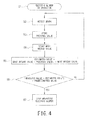
Fig. 4 is a control flowchart of a first example for spark detection and control of the electric vacuum cleaner of the first embodiment of the present invention. -
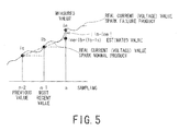
Fig. 5 is a schematic view of a sampling method for use in spark detection in the first example for spark detection and control of the electric vacuum cleaner of the first embodiment of the present invention. -
Fig. 6 is a control flowchart of a second example for spark detection and control of the electric vacuum cleaner of the first embodiment of the present invention. -
Fig. 7 is a schematic view of a sampling method for use in spark detection in the second example for spark detection and control of the electric vacuum cleaner of the first embodiment of the present invention. -
Fig. 8 is a control flowchart of a third example for spark detection and control of the electric vacuum cleaner of the first embodiment of the present invention. -
Fig. 9 is a schematic view of a sampling method for use in spark detection in the third example for spark detection and control of the electric vacuum cleaner of the first embodiment of the present invention. -
Fig. 10 is a table showing the difference in integrated value depending on the power supply voltage, the frequency, and the operating mode in spark detection of the electric vacuum cleaner of the first embodiment of the present invention. -
Fig. 11 is a correlation diagram between a power supply voltage and an integrated value in a strong mode at 50 Hz in spark detection of the electric vacuum cleaner of the first embodiment of the present invention. -
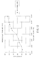
Fig. 12 is a correlation diagram between a power supply voltage and an integrated value in a middle mode at 50 Hz in spark detection of the electric vacuum cleaner of the first embodiment of the present invention. -
Fig. 13 is a correlation diagram between a power supply voltage and an integrated value in a strong mode at 60 Hz in spark detection of the electric vacuum cleaner of the first embodiment of the present invention. -
Fig. 14 is a correlation table between a power supply voltage (detection voltage) and a predetermined value at a rated power supply voltage of 100 V in spark detection of the electric vacuum cleaner of the first embodiment of the present invention. -
Fig. 15 is a block diagram of a control circuit for an electric blower for use in an electric vacuum cleaner of a second embodiment of the present invention. -
Fig. 16 is a control flowchart of a first example for spark detection and control of the electric vacuum cleaner of the second embodiment of the present invention. -
Fig. 17 is a control flowchart of a second example for spark detection and control of the electric vacuum cleaner of the second embodiment of the present invention. -
Fig. 18 is a control flowchart of a third example for spark detection and control of the electric vacuum cleaner of the second embodiment of the present invention. -
Fig. 19 is a control flowchart of spark detection and control of the electric vacuum cleaner of a third embodiment of the present invention. -
Fig. 20 is a correlation graph between an operating time and a spark amount after activation of an electric blower for use in the electric vacuum cleaner of the third embodiment of the present invention. -
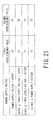
Fig. 21 is a correlation table between a power supply voltage classification and a setting value for use in the electric vacuum cleaner of the third embodiment of the present invention. -
- 1
- electric vacuum cleaner
- 2
- vacuum cleaner body
- 6
- floor suction fitting
- 7
- dust collecting chamber
- 10
- electric blower
- 14
- motor section
- 15
- motor housing
- 16
- stator
- 17
- rotor
- 18
- brush mechanism
- 20
- motor
- 23
- commutator
- 24
- brush holder fixing section
- 25
- brush holder
- 26
- carbon brush
- 30
- control circuit for an electric blower
- 31
- spark detector
- 32
- control unit
- 33
- power regulation section
- 34
- power supply voltage detector
- An electric vacuum cleaner according to a first embodiment of the present invention will be described by referring to the accompanying drawings.
- As illustrated in
Fig. 1 , theelectric vacuum cleaner 1 according to the first embodiment of the present invention comprises: avacuum cleaner body 2; adust collection hose 3 one end of which is connected in an attachable and detachable manner to ahorse connection port 2a formed in a front portion of thevacuum cleaner body 2; anextension tube 5 which is connected in an attachable and detachable manner to ahand operating pipe 4 disposed in the other end of thedust collection hose 3; and a floor suction fitting 6 which is connected in an attachable and detachable manner to a front end of theextension tube 5. - The inside of the
vacuum cleaner body 2 includes a first dust separator and a second dust separator, both of which are communicatively connected to thedust collection hose 3 and are not illustrated. Thevacuum cleaner body 2 includes adust collecting chamber 7 having a dust collector adopting a high-speed separation system which separates dust contained in air flowing at high speeds by gravity difference as the first dust separator; and having a pleat filter as the second dust separator; and anelectric blower 10 which causes a suction negative pressure to act on thedust collecting chamber 7. - As illustrated in
Fig. 2 , theelectric blower 10 includes acentrifugal blower section 12 having asuction port 11; and amotor section 14 having anexhaust port 13. - The
motor section 14 includes amotor housing 15 having anexhaust port 13; astator 16 disposed on an innerperipheral surface 15a of themotor housing 15; arotor 17 rotatably supported inside themotor housing 15; and a pair ofbrush mechanisms 18 disposed in themotor housing 15 and electrically connected to therotor 17. Thestator 16, therotor 17, and a pair ofbrush mechanisms 18 constitute amotor 20. - The
rotor 17 is disposed inside thestator 16. Therotor 17 includes arotor shaft 21 disposed at the shaft center; a field coil 22 (rotor coil) wound around therotor shaft 21; and acommutator 23 electrically connected to thefield coil 22 and disposed on therotor shaft 21. - The
brush mechanism 18 includes abrush holder 25 penetrated through a brushholder fixing section 24; acarbon brush 26 slidably housed in thebrush holder 25; and acoil spring 27 which presses and urges thecarbon brush 26 to thecommutator 23 of therotor 17. - As illustrated in
Fig. 3 , acontrol circuit 30 for an electric blower includes theelectric blower 20, aspark detector 31, acontrol unit 32, apower regulation section 33, and powersupply voltage detector 34. - As the
spark detector 31, a current transformer which detects a current of theelectric blower 20 is used. The current detected by the current transformer is converted to a voltage value. As the power supply, for example, a commercial power supply of rated 100 V is used. - When a spark occurs in the brush mechanism 57, the current value tends to be lowered.
- The
control unit 32 includes a microcomputer and a memory. As thepower regulation section 33, for example, a triac is used. - The
spark detector 31 detects a current flowing through theelectric blower 20. Based on the spark detection information, thecontrol circuit 30 controls theelectric blower 20 through thecontrol unit 32 and thepower regulation section 33. - The power
supply voltage detector 34 detects a power supply voltage, and inputs the power supply voltage information to thecontrol unit 32. - Next, the spark detection and control of the electric blower for use in the electric vacuum cleaner according to the first embodiment.
- Based on
Figs. 4 and5 , the first example of the spark detection and control will be described. - The
electric vacuum cleaner 1 is used and theelectric blower 10 is turned on (S1). - A plurality of samplings is performed at equal time intervals. Samplings are performed, for example, at a half-frequency of 50 Hz at a sampling interval of 10 ms at 100 points. When phase control is performed, the samplings are performed only when current flows.
- For example, the
spark detector 31 detects a current flowing through theelectric blower 10 and converts the current to a voltage (S2). - The voltage value is stored in the
control unit 32 as a previously measured value Ia of the sampling (n-2) (S3). - Further, the
spark detector 31 detects a current flowing through theelectric blower 10, converts the current to a voltage, and stores the voltage value in thecontrol unit 32 as the most recently measured value Ib of the sampling (n-1) (S4). - The
control unit 32 calculates an estimated value Ine (S5). - The estimated value Ine is estimated from a previously measured value Ia and a most recently measured value Ib, and more specifically, a difference between the previously measured value Ia and the most recently measured value Ib is added to the most recently measured value Ib.
- That is, Ine = Ib + (Ib-Ia).
- The
control unit 32 determines whether or not the absolute value of a difference between the estimated value Ine and the measured value In is greater than the predetermined value Is (S6). - That is, the
control unit 32 determines whether |In-Ine| > Is or not. - The current value in the sampling n is used as the measured value In. The predetermined value Is is calculated by experiment in advance in a state in which the
carbon brush 26 is normal. - When the absolute value of the difference between the estimated value Ine and the measured value In is greater than the predetermined value Is (YES in S6), the
control circuit 30 stops theelectric blower 10 through thecontrol unit 32 and the power regulation section 33 (S7). - The state in which the absolute value of the difference between the estimated value Ine and the measured value In is greater than the predetermined value Is indicates that a spark occurs by the friction between the
commutator 23 and thecarbon brush 26 in theelectric blower 10. Thus, thecontrol circuit 30 stops theelectric blower 10 to prevent smoking and ignition from occurring in theelectric blower 10. - When a determination is made in S6 that the absolute value of the difference between the estimated value Ine and the measured value In is not greater than the predetermined value Is (NO in S6), the process returns to S2, in which the subsequent processes are repeated in the same manner.
- The state in which the absolute value of the difference between the estimated value Ine and the measured value In is not greater than the predetermined value Is indicates that a spark does not occurs by the friction between the
commutator 23 and thecarbon brush 26 in theelectric blower 10. Thus, thecontrol circuit 30 allows theelectric blower 10 to continue operating. - The first example of the present spark detection and control determines whether or not a spark occurs in such a manner that the difference between a previous value and a most recent value of the sampled measured values is obtained to estimate a next value; and when the absolute value of the difference between the estimated value and the next measured value is greater than the predetermined value, the operation of the electric blower is stopped. Thus, unlike the conventional method, without misdetection and with accuracy, the first example of the present spark detection and control detects a spark caused by the friction between the commutator and the carbon brush, safely stops the operation of the electric blower, and prevents smoking and ignition from occurring in the electric blower.
- Based on
Figs. 6 and7 , the second example of the spark detection and control will be described. - The same steps as the S1 to S5 of the first example illustrated in
Fig. 4 are executed by repeating a plurality of n-2 times at the same half-frequency (S1 to S15). - The detection steps are repeated a plurality of n-2 times and the
control unit 32 determines whether or not the integrated absolute value of the difference between the measured value In1 and the estimated value Ine1 is greater than the predetermined value Is (S16). - That is, the
control unit 32 determines whether |In1-Ine1| - When the summated absolute value of the difference between the measured value In1 and the estimated value Ine1 is greater than the predetermined value Is (YES in S16), the
control circuit 30 stops theelectric blower 10 through thecontrol unit 32 and the power regulation section 33 (S17). - The second example of the present spark detection and control determines whether or not a spark occurs in such a manner that the detection steps are repeated a plurality of n-2 times; and the absolute value of the difference between the measured value and the estimated value is integrated, allowing the measured value and the estimated value to be unvarying and stable. Thus, unlike the conventional method, without misdetection and with more accuracy, the second example of the present spark detection and control detects a spark caused by the friction between the commutator and the carbon brush, safely stops the operation of the electric blower, and prevents smoking and ignition from occurring in the electric blower.
- Based on
Figs. 8 and9 , the third example of the spark detection and control will be described. - The same steps as the S11 to S15 of the second example illustrated in
Fig. 6 are executed by repeating a plurality of N times at the same frequency (S) (S21 to S25). - The detection steps are repeated a plurality of n-2 times to integrate the absolute value of the difference between the measured value In2 and the estimated value Ine2, and the integrated value is stored.
- Further, as illustrated in
Fig. 9 , in the next cycle (S+1), for example, the detection steps are repeated a plurality of n-2 times in the same phase, and further in a cycle (S+Nn), the detection steps are repeated a plurality of (S+Nn) times. - The integrated values of the obtained absolute value of the difference between the measured value In2 and the estimated value Ine2 are averaged for each frequency of the power supply (n times) to determine whether or not the averaged value is greater than the predetermined value Is (S26).
- Subsequently, in the same manner as in S6 of the first example illustrated in
Fig. 4 , when YES, the process moves to S27; when NO, the process returns to S22. - The third example of the present spark detection and control determines whether or not a spark occurs in such a manner that in a plurality of cycles, the detection steps are repeated a plurality of times; and the integrated values of the absolute value of the difference between the measured value In2 and the estimated value Ine2 are averaged for each frequency of the power supply (n times), allowing exceptional values to be removed and the unvarying and stable integrated values to be used. Thus, unlike the conventional method, without misdetection and with more accuracy, the third example of the present spark detection and control detects a spark caused by the friction between the commutator and the carbon brush, safely stops the operation of the electric blower, and prevents smoking and ignition from occurring in the electric blower.
- The fourth example of the present spark detection and control changes the predetermined value according to the power supply voltage value in the first to third examples.
- As illustrated in
Figs 10 "(a) Operating mode (strong) and (b) Operating mode (middle)" to 13, as each power supply voltage in both 50 Hz and 60 Hz increases, the integrated value also increases. It is understood that in any power supply voltage in both 50 Hz and 60 Hz, the integrated values in 60 Hz are greater than the integrated values in 50 Hz. - As understood from
Figs 10(a) and (b) ,11 , and12 , the integrated values vary depending on the strong mode and the middle mode in 50 Hz. - Therefore, the predetermined value needs to be changed according to the change in power supply voltage and the frequency.
- For example, the power
supply voltage detector 34 illustrated inFig. 3 detects a power supply voltage and the power supply voltage information is inputted to thecontrol unit 32 which rewrites a predetermined value preliminarily stored in the memory. - When the power supply voltage is rated 100 V, the relation between the power supply voltage (detection voltage) and the predetermined value is as illustrated in
Fig. 14 . - As illustrated in
Fig. 14 , the predetermined value is determined for each classification of power supply voltage. For example, the predetermined value is A for the voltage < 80V; the predetermined value is B for 80 V ≤ the voltage < 90 V; the predetermined value is C for 90 V ≤ the voltage < 100 V; and the predetermined value is D for 100 V ≤ the voltage. Thus, the predetermined value is rewritten for each 10 V. - The fourth example of the present spark detection and control determines whether or not a spark occurs in such a manner that in addition to the detection steps in the first to third examples of the spark detection and control, the predetermined value is changed according to the power supply voltage value. Thus, unlike the conventional method, without misdetection, according to the power supply voltage, the fourth example of the present spark detection and control accurately detects a spark caused by the friction between the commutator and the carbon brush, safely stops the operation of the electric blower, and prevents smoking and ignition from occurring in the electric blower.
- Thus, the electric vacuum cleaner according to the first embodiment of the present invention detects a spark caused by the friction between the commutator and the carbon brush of the electric blower, stops the operation of the electric blower, and prevents smoking and ignition from occurring in the electric blower.
- Now, the electric vacuum cleaner according to the second embodiment of the present invention will be described.
- The electric vacuum cleaner according to the second embodiment not only has the same configuration as that of the electric vacuum cleaner according to the first embodiment but also has a
notification unit 35 connected to thecontrol unit 32 as illustrated inFig. 15 . - The spark detection and control by the control circuit of the electric vacuum cleaner according to the second embodiment will be described.
- The steps S31 to S36 in the flowchart of the second example of the present spark detection and control illustrated in
Fig. 16 are the same as the steps S1 to S6 in the first example of the electric vacuum cleaner according to the first embodiment illustrated inFig. 4 , and thus the description will be omitted. - When the absolute value of the difference between the estimated value Ine and the measured value In is greater than the predetermined value Is, it indicates that a spark occurs by the friction between the
commutator 23 and thecarbon brush 26 of theelectric blower 10. Thus, thecontrol unit 32 stops theelectric blower 10 to prevent smoking and ignition from occurring in theelectric blower 10. At this time, thenotification unit 35 notifies that a spark occurs and theelectric blower 10 stops (S37). - The stop information of the
electric blower 10 is stored in a memory of the control unit 32 (S38). - When and after the memory of the
control unit 32 stores the stop information, a subsequent operation request from a control switch 4a will be ignored to prevent theelectric blower 10 from operating (S39). - Further, when the memory is unplugged to stop supplying power to the
electric vacuum cleaner 1, the memory holds the stop information therein; and when the power plug is inserted again to supply power to theelectric vacuum cleaner 1, an operation request from a control switch 4a will be ignored to prevent theelectric blower 10 from operating. - The first example of the spark detection and control determines whether or not a spark occurs in such a manner that the difference between a previous value and a most recent value of sampled measured values is obtained to estimate a next value; and when the difference between the estimated value and the next measured value is greater than the predetermined value, the operation of the electric blower is stopped. Additionally, after the operation is stopped, a control apparatus is activated to store the stop information in the memory, and a subsequent operation request from outside such as a control switch is ignored to prevent the electric blower from operating and to prevent smoking and ignition from occurring in the electric blower.
- Unlike the first example which, when a spark occurrence is determined, stops the operation of the electric blower, and when and after the operation is stopped, prevents the electric blower from operating, the second example of the present spark detection and control stops the subsequent operation of the electric blower when and after the number of operation stops reaches a predetermined times.
- By referring to
Fig. 17 , the second example of the present spark detection and control will be described. - The steps S41 to S46 are the same as the steps S1 to S6 in the first example of the electric vacuum cleaner according to the first embodiment illustrated in
Fig. 4 , and thus the description will be omitted. - In S47, a spark occurrence is detected and the operation of the
electric blower 10 is stopped through thecontrol unit 32 and thepower regulation section 33. Then, when the operation of theelectric blower 10 is stopped, a first stop is stored in the memory of thecontrol unit 32. When the spark occurrence is removed, the operation of theelectric blower 10 is resumed. When a spark occurrence is detected again, the number of stops is incremented by 1 (S48). - The
control unit 32 determines whether or not the number of stops reaches a predetermined number of times (S49). - When the number of stops reaches a predetermined number of times (YES), the memory of the
control unit 32 stores the number of stops (S50). - Subsequently, an operation request from a control switch 4a will be ignored to prevent the
electric blower 10 from operating (S51). - When a determination is made in S49 that the number of stops does not reach the predetermined number of times (NO in S49), the
electric blower 10 is placed in a normal wait state (S52). - This state is the same state in which the stop button is pressed.
- In the second example of the present spark detection and control, when the number of stops does not reach a predetermined number of times, the operation of the electric blower is resumed. When a spark occurs, the operation momentarily stops, but the operation is resumed. Thus, the second example improves convenience and prevents smoking and ignition from occurring in the electric blower.
- Unlike the second example which stores the number of operation stops, the third example of the present spark detection and control erases the number of operation stops stored in the memory when normal operation is determined.
- By referring to
Fig. 18 , the third example of the spark detection and control will be described. - The third example of the present spark detection and control detects a spark in the same manner as in the steps S1 to S6 of the first example of the first embodiment illustrated in
Fig. 4 . - A determination is made as to whether a spark is detected and the operation of the electric blower is stopped or not (S61).
- When no spark is detected and the operation is not stopped (NO in S61), a determination is made as to whether the operation is normal operation or not (S62).
- When the electric blower is in operation for 30 to 60 seconds without an error, the operation is determined to be normal.
- When the operation is determined to be normal (YES in S62), the stop count is cleared to zero (S63).
- After the count is cleared, the process returns to S61.
- Meanwhile, when a determination is made in S61 that a spark is detected and the operation of the electric blower is stopped (YES in S61), the steps S64 to S68, which are the same as the steps S48 to S52 in the second example, are executed.
- When a determination is made in S62 that the electric blower is not in normal operation (NO in S62), the process returns to S61.
- In the third example of the present spark detection and control, when the electric blower returns to normal, the count is cleared; and when a spark occurs, the operation momentarily stops, but the operation is resumed. Thus, the third example improves convenience and prevents smoking and ignition from occurring in the electric blower.
- The electric vacuum cleaner according to the second embodiment of the present invention is free from misdetection to ensure reliable and stable error detection; not only detects a spark caused by the friction between the commutator and the carbon brush of the electric blower and stops the operation of the electric blower but also after the operation is stopped, activates a control apparatus to control the electric blower to prevent smoking and ignition from occurring in the electric blower; and is ease of use.
- Now, the electric vacuum cleaner according to the third embodiment of the present invention will be described.
- The electric vacuum cleaner according to the third embodiment has the same configuration as that of the electric vacuum cleaner according to the first embodiment.
- The spark detection and control by the control circuit of the electric vacuum cleaner according to the third embodiment will be described.
- Based on
Fig. 19 , the spark detection and control of the electric vacuum cleaner according to the third embodiment will be described. - Note that like an ordinary electric blower, when the
electric blower 10 is activated, the rate of spark occurrence is high and then the rate tends to be lowered. - The
electric vacuum cleaner 1 is used and theelectric blower 10 is activated (S71). - Spark detection is performed (S72).
- The spark detection is performed in the same manner as in the steps S1 to S6 of the first example of the first embodiment illustrated in
Fig. 4 . - The
control unit 32 stores the absolute value of the difference between the estimated value Ine and the measured value In in a storage unit of thecontrol unit 32 as a detection value (spark amount) based on the spark detection information. - After the
electric blower 10 is activated, thecontrol unit 32 detects whether the predetermined time has elapsed or not (S73). -
Fig. 20 is a correlation graph between an operating time and a spark amount after the electric blower is activated. As illustrated inFig. 20 , the predetermined time is set to, for example, two minutes when the spark amount becomes stable two minutes after the activation. - When the predetermined time has not elapsed since the activation (NO in S73), a determination is made as to whether or not the detection value is equal to or greater than the first predetermined value (S74).
- Note that the predetermined value is determined by experiment as follows.
- The time from when the electric blower is activated to when the spark amount becomes stable and the spark amount are measured. The measurements are confirmed on a plurality of electric blowers. From these experiments, the highest spark amount at activation, the time taken until the spark amount becomes stable, and the spark amount are obtained and multiplied by a safety factor to set the predetermined value.
- Here, the first predetermined value is obtained by multiplying a maximum detection value illustrated in
Fig. 20 by a safety factor (for example, 1.1) for preventing malfunction. - When the detection value is equal to or greater than the first predetermined value (YES in S74), the
control unit 32 stops the operation of the electric blower 10 (S75). - When the detection value is equal to or greater than the first predetermined value, it indicates that within the predetermined time after the activation, a spark has occurred by the friction between the
commutator 23 and thecarbon brush 26 in theelectric blower 10. Thus, thecontrol unit 32 stops the operation of theelectric blower 10 to prevent smoking and ignition from occurring in theelectric blower 10. - When a determination is made in S73 that the predetermined time has elapsed since the activation (YES in S73), a determination is made as to whether or not the detection value is equal to or greater than the second predetermined value (S76).
- Here, the second predetermined value is obtained by multiplying a stable value illustrated in
Fig. 20 by a safety factor (for example, 1.4) for preventing malfunction. - When the detection value is equal to or greater than the second predetermined value (YES in S76), the
control unit 32 stops the operation of the electric blower 10 (S75). - When the detection value is equal to or greater than the second predetermined value, it indicates that during stable operation after the predetermined time has elapsed since the activation, a spark has occurred by the friction between the
commutator 23 and thecarbon brush 26 in theelectric blower 10. Thus, thecontrol unit 32 stops the operation of theelectric blower 10 to prevent smoking and ignition from occurring in theelectric blower 10. - When a determination is made in S74 that the detection value is not equal to or greater than the first predetermined value (NO in S74), the process returns to S72, in which the spark detection is repeatedly performed.
- When a determination is made in S76 that the detection value is not equal to or greater than the second predetermined value (NO in S76), the process returns to S72, in which the spark detection is repeatedly performed.
- Thus, the state in which a determination is made in S74 and S76 that the detection value is not equal to or greater than the first and second predetermined values respectively indicates that a spark does not occurs by the friction between the
commutator 23 and thecarbon brush 26 in theelectric blower 10. Thus, thecontrol circuit 30 allows theelectric blower 10 to continue operating. - Note that
Fig. 20 is a correlation graph between an operating time and a spark amount after activation of an electric blower, where the first setting value and the second setting value are determined for each classification of power supply voltage as illustrated inFig. 21 . For example, for AC90V ≤ the power supply voltage < AC100V, the first setting value is C1, while the second setting value is C2. - These setting values may be changed for each classification of the power supply voltage as described above, for each operating mode of the electric blower as described in the first embodiment, for each frequency of the power supply, or a combination thereof.
- Note that the third embodiment specifies two setting values: a first setting value and a second setting value lower than the first setting value, but the setting values may further include a third setting value lower than the second setting value, and further may include a plurality of setting values. Note also that the power supply is not limited to an AC power supply, but may be a cordless charging system.
- As described above, according to the present electric vacuum cleaner, within a predetermined time since the activation of the electric blower, when the detection value based on the spark detection information from the spark detector is greater than the first predetermined value, the electric blower is subject to control such as stop; and after the predetermined time has elapsed, when the detection value is greater than the second predetermined value lower than the first predetermined value, the electric blower is subject to control such as stop.
- Therefore, unlike the conventional method in which one large predetermined value is set within a predetermined time and thus the electric blower cannot be stopped by detecting a spark failure at stable operation or one small predetermined value is set at stable operation and thus the electric blower is stopped although the electric blower is operating normally at activation, the present electric vacuum cleaner of the third embodiment does not stop the normally operating electric blower, detects a spark caused by the friction between a commutator and a carbon brush in the electric blower, and stops the operation of the electric blower to prevent smoking and ignition from occurring in the electric blower.
- Thus, the present electric vacuum cleaner of the third embodiment does not stop the normally operating electric blower, detects a spark caused by the friction between a commutator and a carbon brush in the electric blower, and stops the operation of the electric blower to prevent smoking and ignition from occurring in the electric blower, thereby achieving a reliable electric vacuum cleaner.
Claims (15)
- An electric vacuum cleaner comprising:a dust collecting chamber disposed in a vacuum cleaner body; an electric blower that causes a suction negative pressure to act on the dust collecting chamber; a spark detector that detects a spark caused by friction between a commutator and a carbon brush of the electric blower; and a control unit that controls the electric blower based on spark detection information from the spark detector, whereinthe spark detector calculates a difference between a previous value and a most recent value of sampled values, and estimates a next value from the difference; and when an absolute value of a difference between an estimated value and a measured value is greater than a predetermined value, the control unit stops operation of the electric blower.
- The electric vacuum cleaner according to claim 1, wherein the absolute value of the difference between the estimated value and the measured value is integrated a predetermined number of times, and when an integrated value is greater than the predetermined value, the operation of the electric blower is stopped.
- The electric vacuum cleaner according to claim 2, wherein the spark detector performs sampling for each of a plurality of frequency of the power supplies and averages integrated values for each frequency of the power supply.
- The electric vacuum cleaner according to any one of claims 1 to 3, wherein the spark detector performs sampling when power is supplied to the electric blower.
- The electric vacuum cleaner according to any one of claims 1 to 4, further comprising a power supply voltage detector that detects a power supply voltage, wherein according to a voltage detected by the power supply voltage detector, the predetermined value is changed.
- The electric vacuum cleaner according to any one of claims 1 to 4, further comprising a plurality of operating modes, wherein according to an operating mode, the predetermined value is changed.
- The electric vacuum cleaner according to any one of claims 1 to 4, further comprising a power supply frequency detector that detects the frequency of the power supply, wherein according to a frequency detected by the power supply frequency detector, the predetermined value is changed.
- The electric vacuum cleaner according to claim 1, wherein
when the difference between the estimated value and the measured value is greater than the predetermined value, the spark detector determines that a spark occurs; and
the control unit stops the operation of the electric blower, and after the operation of the electric blower is stopped, prevents reactivation of the electric blower. - The electric vacuum cleaner according to claim 8, wherein when the spark detector determines spark occurrence, the control unit stops the operation of the electric blower and enables the electric blower to continue operating until the number of stops reaches a predetermined number of times.
- The electric vacuum cleaner according to claim 9, wherein even if the electric blower momentarily stops due to spark occurrence, when the electric blower returns to normal, the stored stop count is cleared.
- The electric vacuum cleaner according to any one of claims 8 to 10, further comprising a notification apparatus that detects spark occurrence and notifies that the electric blower stops.
- The electric vacuum cleaner according to claim 1, wherein
the predetermined value comprises a plurality of predetermined values;
within a predetermined time from the activation of the electric blower, a first predetermined value is set; and
after the predetermined time has elapsed, a predetermined value lower than the first predetermined value is set. - The electric vacuum cleaner according to claim 12, wherein the plurality of predetermined values is set for each operating mode of the electric blower; and the predetermined value is changed by switching the operating mode.
- The electric vacuum cleaner according to claim 12, wherein the plurality of predetermined values is set for each frequency of the power supply; the frequency of the power supply is detected; and based on the detected results, the predetermined value is changed.
- The electric vacuum cleaner according to claim 12, further comprising a power supply voltage detector which detects a power supply voltage value, wherein the plurality of predetermined values is set for each classification of power supply voltage; and the predetermined value is changed for each classification of the voltage detected by the power supply voltage detector.
Applications Claiming Priority (4)
| Application Number | Priority Date | Filing Date | Title |
|---|---|---|---|
| JP2008331850A JP5135203B2 (en) | 2008-12-26 | 2008-12-26 | Electric vacuum cleaner |
| JP2009019971A JP5380090B2 (en) | 2009-01-30 | 2009-01-30 | Electric vacuum cleaner |
| JP2009033783A JP2010187824A (en) | 2009-02-17 | 2009-02-17 | Electric vacuum cleaner |
| PCT/JP2009/071753 WO2010074282A1 (en) | 2008-12-26 | 2009-12-28 | Electric vacuum cleaner |
Publications (3)
| Publication Number | Publication Date |
|---|---|
| EP2387929A1 true EP2387929A1 (en) | 2011-11-23 |
| EP2387929A4 EP2387929A4 (en) | 2016-03-09 |
| EP2387929B1 EP2387929B1 (en) | 2020-03-18 |
Family
ID=42287883
Family Applications (1)
| Application Number | Title | Priority Date | Filing Date |
|---|---|---|---|
| EP09835075.4A Active EP2387929B1 (en) | 2008-12-26 | 2009-12-28 | Electric vacuum cleaner |
Country Status (5)
| Country | Link |
|---|---|
| EP (1) | EP2387929B1 (en) |
| KR (1) | KR101252433B1 (en) |
| CN (1) | CN102292012B (en) |
| RU (1) | RU2494667C2 (en) |
| WO (1) | WO2010074282A1 (en) |
Cited By (2)
| Publication number | Priority date | Publication date | Assignee | Title |
|---|---|---|---|---|
| JP2017055799A (en) * | 2015-09-14 | 2017-03-23 | 東芝ライフスタイル株式会社 | Vacuum cleaner |
| WO2020163336A1 (en) * | 2019-02-06 | 2020-08-13 | Techtronic Cordless Gp | A cleaning system comprising a system for preventing the motor from overheating and a method therefore |
Families Citing this family (2)
| Publication number | Priority date | Publication date | Assignee | Title |
|---|---|---|---|---|
| CN103051141A (en) * | 2013-01-14 | 2013-04-17 | 胡刚 | Brushless electric machine for dust collector |
| JP6246511B2 (en) * | 2013-07-03 | 2017-12-13 | 東芝ライフスタイル株式会社 | Electric vacuum cleaner |
Family Cites Families (10)
| Publication number | Priority date | Publication date | Assignee | Title |
|---|---|---|---|---|
| JPS60226739A (en) * | 1984-04-24 | 1985-11-12 | Hitachi Ltd | Rectifier spark monitoring device |
| JPH0473036A (en) * | 1990-07-16 | 1992-03-09 | Matsushita Electric Ind Co Ltd | vacuum cleaner |
| JP3352300B2 (en) * | 1995-11-14 | 2002-12-03 | 株式会社東芝 | Rectification spark trend management device |
| JP2000116582A (en) * | 1998-10-14 | 2000-04-25 | Sharp Corp | Electric vacuum cleaner |
| JP4496573B2 (en) * | 1999-11-10 | 2010-07-07 | パナソニック株式会社 | Control circuit for electric blower and vacuum cleaner |
| JP2006204470A (en) * | 2005-01-27 | 2006-08-10 | Toshiba Tec Corp | Electric vacuum cleaner |
| JP4700986B2 (en) * | 2005-03-16 | 2011-06-15 | 株式会社ユニバーサルエンターテインメント | Game machine |
| JP4231015B2 (en) * | 2005-03-16 | 2009-02-25 | シャープ株式会社 | Electric vacuum cleaner |
| JP4726758B2 (en) | 2006-09-27 | 2011-07-20 | 三菱電機株式会社 | Electric motor control device, vacuum cleaner and hand dryer |
| JP5061638B2 (en) * | 2007-02-20 | 2012-10-31 | 株式会社明電舎 | Signal estimation device |
-
2009
- 2009-12-28 KR KR1020117017084A patent/KR101252433B1/en not_active Expired - Fee Related
- 2009-12-28 EP EP09835075.4A patent/EP2387929B1/en active Active
- 2009-12-28 WO PCT/JP2009/071753 patent/WO2010074282A1/en not_active Ceased
- 2009-12-28 RU RU2011131052/12A patent/RU2494667C2/en not_active IP Right Cessation
- 2009-12-28 CN CN200980155500.XA patent/CN102292012B/en active Active
Non-Patent Citations (1)
| Title |
|---|
| See references of WO2010074282A1 * |
Cited By (3)
| Publication number | Priority date | Publication date | Assignee | Title |
|---|---|---|---|---|
| JP2017055799A (en) * | 2015-09-14 | 2017-03-23 | 東芝ライフスタイル株式会社 | Vacuum cleaner |
| WO2020163336A1 (en) * | 2019-02-06 | 2020-08-13 | Techtronic Cordless Gp | A cleaning system comprising a system for preventing the motor from overheating and a method therefore |
| CN113613537A (en) * | 2019-02-06 | 2021-11-05 | 创科无线普通合伙 | Cleaning system including system for preventing overheating of motor and method thereof |
Also Published As
| Publication number | Publication date |
|---|---|
| RU2494667C2 (en) | 2013-10-10 |
| EP2387929A4 (en) | 2016-03-09 |
| CN102292012A (en) | 2011-12-21 |
| EP2387929B1 (en) | 2020-03-18 |
| RU2011131052A (en) | 2013-02-10 |
| KR101252433B1 (en) | 2013-04-08 |
| WO2010074282A1 (en) | 2010-07-01 |
| KR20110110210A (en) | 2011-10-06 |
| CN102292012B (en) | 2014-05-28 |
Similar Documents
| Publication | Publication Date | Title |
|---|---|---|
| EP3654810B1 (en) | Vacuum cleaner and control method thereof | |
| KR102266750B1 (en) | Electric cleaner | |
| EP2387929B1 (en) | Electric vacuum cleaner | |
| JP2004135835A (en) | Electric vacuum cleaner | |
| CN112292795A (en) | Charging type dust collector | |
| EP3494853A1 (en) | Electric vacuum cleaner | |
| KR101284492B1 (en) | Electric vacuum cleaner | |
| JP5395518B2 (en) | Electric vacuum cleaner | |
| JP3705163B2 (en) | Vacuum cleaner | |
| JP2010213797A (en) | Electric vacuum cleaner | |
| JP2005168977A (en) | Electric vacuum cleaner | |
| JP5364449B2 (en) | Electric vacuum cleaner | |
| JP2014033725A (en) | Vacuum cleaner | |
| JP6382523B2 (en) | Electric vacuum cleaner | |
| JP3763396B2 (en) | Electric vacuum cleaner | |
| JP5135203B2 (en) | Electric vacuum cleaner | |
| JP2010187824A (en) | Electric vacuum cleaner | |
| JP5380090B2 (en) | Electric vacuum cleaner | |
| JP2016158784A (en) | Vacuum cleaner | |
| KR100562545B1 (en) | Semi-Automatic Vacuum Cleaner | |
| JP6089211B2 (en) | Rechargeable vacuum cleaner | |
| JP7186112B2 (en) | vacuum cleaner | |
| JP2017055799A (en) | Vacuum cleaner | |
| JP6628528B2 (en) | Electric vacuum cleaner | |
| JP2017169704A (en) | Vacuum cleaner |
Legal Events
| Date | Code | Title | Description |
|---|---|---|---|
| PUAI | Public reference made under article 153(3) epc to a published international application that has entered the european phase |
Free format text: ORIGINAL CODE: 0009012 |
|
| 17P | Request for examination filed |
Effective date: 20110720 |
|
| AK | Designated contracting states |
Kind code of ref document: A1 Designated state(s): AT BE BG CH CY CZ DE DK EE ES FI FR GB GR HR HU IE IS IT LI LT LU LV MC MK MT NL NO PL PT RO SE SI SK SM TR |
|
| DAX | Request for extension of the european patent (deleted) | ||
| RA4 | Supplementary search report drawn up and despatched (corrected) |
Effective date: 20160208 |
|
| RIC1 | Information provided on ipc code assigned before grant |
Ipc: A47L 9/28 20060101AFI20160202BHEP |
|
| RAP1 | Party data changed (applicant data changed or rights of an application transferred) |
Owner name: TOSHIBA LIFESTYLE PRODUCTS & SERVICES CORPORATION |
|
| GRAP | Despatch of communication of intention to grant a patent |
Free format text: ORIGINAL CODE: EPIDOSNIGR1 |
|
| STAA | Information on the status of an ep patent application or granted ep patent |
Free format text: STATUS: GRANT OF PATENT IS INTENDED |
|
| GRAS | Grant fee paid |
Free format text: ORIGINAL CODE: EPIDOSNIGR3 |
|
| GRAA | (expected) grant |
Free format text: ORIGINAL CODE: 0009210 |
|
| STAA | Information on the status of an ep patent application or granted ep patent |
Free format text: STATUS: THE PATENT HAS BEEN GRANTED |
|
| INTG | Intention to grant announced |
Effective date: 20200121 |
|
| AK | Designated contracting states |
Kind code of ref document: B1 Designated state(s): AT BE BG CH CY CZ DE DK EE ES FI FR GB GR HR HU IE IS IT LI LT LU LV MC MK MT NL NO PL PT RO SE SI SK SM TR |
|
| REG | Reference to a national code |
Ref country code: GB Ref legal event code: FG4D |
|
| REG | Reference to a national code |
Ref country code: DE Ref legal event code: R096 Ref document number: 602009061496 Country of ref document: DE |
|
| REG | Reference to a national code |
Ref country code: AT Ref legal event code: REF Ref document number: 1244937 Country of ref document: AT Kind code of ref document: T Effective date: 20200415 Ref country code: IE Ref legal event code: FG4D |
|
| PG25 | Lapsed in a contracting state [announced via postgrant information from national office to epo] |
Ref country code: FI Free format text: LAPSE BECAUSE OF FAILURE TO SUBMIT A TRANSLATION OF THE DESCRIPTION OR TO PAY THE FEE WITHIN THE PRESCRIBED TIME-LIMIT Effective date: 20200318 Ref country code: NO Free format text: LAPSE BECAUSE OF FAILURE TO SUBMIT A TRANSLATION OF THE DESCRIPTION OR TO PAY THE FEE WITHIN THE PRESCRIBED TIME-LIMIT Effective date: 20200618 |
|
| REG | Reference to a national code |
Ref country code: NL Ref legal event code: MP Effective date: 20200318 |
|
| PG25 | Lapsed in a contracting state [announced via postgrant information from national office to epo] |
Ref country code: LV Free format text: LAPSE BECAUSE OF FAILURE TO SUBMIT A TRANSLATION OF THE DESCRIPTION OR TO PAY THE FEE WITHIN THE PRESCRIBED TIME-LIMIT Effective date: 20200318 Ref country code: SE Free format text: LAPSE BECAUSE OF FAILURE TO SUBMIT A TRANSLATION OF THE DESCRIPTION OR TO PAY THE FEE WITHIN THE PRESCRIBED TIME-LIMIT Effective date: 20200318 Ref country code: HR Free format text: LAPSE BECAUSE OF FAILURE TO SUBMIT A TRANSLATION OF THE DESCRIPTION OR TO PAY THE FEE WITHIN THE PRESCRIBED TIME-LIMIT Effective date: 20200318 Ref country code: GR Free format text: LAPSE BECAUSE OF FAILURE TO SUBMIT A TRANSLATION OF THE DESCRIPTION OR TO PAY THE FEE WITHIN THE PRESCRIBED TIME-LIMIT Effective date: 20200619 Ref country code: BG Free format text: LAPSE BECAUSE OF FAILURE TO SUBMIT A TRANSLATION OF THE DESCRIPTION OR TO PAY THE FEE WITHIN THE PRESCRIBED TIME-LIMIT Effective date: 20200618 |
|
| REG | Reference to a national code |
Ref country code: LT Ref legal event code: MG4D |
|
| PG25 | Lapsed in a contracting state [announced via postgrant information from national office to epo] |
Ref country code: NL Free format text: LAPSE BECAUSE OF FAILURE TO SUBMIT A TRANSLATION OF THE DESCRIPTION OR TO PAY THE FEE WITHIN THE PRESCRIBED TIME-LIMIT Effective date: 20200318 |
|
| PG25 | Lapsed in a contracting state [announced via postgrant information from national office to epo] |
Ref country code: SM Free format text: LAPSE BECAUSE OF FAILURE TO SUBMIT A TRANSLATION OF THE DESCRIPTION OR TO PAY THE FEE WITHIN THE PRESCRIBED TIME-LIMIT Effective date: 20200318 Ref country code: EE Free format text: LAPSE BECAUSE OF FAILURE TO SUBMIT A TRANSLATION OF THE DESCRIPTION OR TO PAY THE FEE WITHIN THE PRESCRIBED TIME-LIMIT Effective date: 20200318 Ref country code: IS Free format text: LAPSE BECAUSE OF FAILURE TO SUBMIT A TRANSLATION OF THE DESCRIPTION OR TO PAY THE FEE WITHIN THE PRESCRIBED TIME-LIMIT Effective date: 20200718 Ref country code: RO Free format text: LAPSE BECAUSE OF FAILURE TO SUBMIT A TRANSLATION OF THE DESCRIPTION OR TO PAY THE FEE WITHIN THE PRESCRIBED TIME-LIMIT Effective date: 20200318 Ref country code: SK Free format text: LAPSE BECAUSE OF FAILURE TO SUBMIT A TRANSLATION OF THE DESCRIPTION OR TO PAY THE FEE WITHIN THE PRESCRIBED TIME-LIMIT Effective date: 20200318 Ref country code: LT Free format text: LAPSE BECAUSE OF FAILURE TO SUBMIT A TRANSLATION OF THE DESCRIPTION OR TO PAY THE FEE WITHIN THE PRESCRIBED TIME-LIMIT Effective date: 20200318 Ref country code: CZ Free format text: LAPSE BECAUSE OF FAILURE TO SUBMIT A TRANSLATION OF THE DESCRIPTION OR TO PAY THE FEE WITHIN THE PRESCRIBED TIME-LIMIT Effective date: 20200318 Ref country code: PT Free format text: LAPSE BECAUSE OF FAILURE TO SUBMIT A TRANSLATION OF THE DESCRIPTION OR TO PAY THE FEE WITHIN THE PRESCRIBED TIME-LIMIT Effective date: 20200812 |
|
| REG | Reference to a national code |
Ref country code: AT Ref legal event code: MK05 Ref document number: 1244937 Country of ref document: AT Kind code of ref document: T Effective date: 20200318 |
|
| REG | Reference to a national code |
Ref country code: DE Ref legal event code: R097 Ref document number: 602009061496 Country of ref document: DE |
|
| REG | Reference to a national code |
Ref country code: DE Ref legal event code: R082 Ref document number: 602009061496 Country of ref document: DE Representative=s name: HL KEMPNER PATENTANWALT, RECHTSANWALT, SOLICIT, DE |
|
| PLBE | No opposition filed within time limit |
Free format text: ORIGINAL CODE: 0009261 |
|
| STAA | Information on the status of an ep patent application or granted ep patent |
Free format text: STATUS: NO OPPOSITION FILED WITHIN TIME LIMIT |
|
| PG25 | Lapsed in a contracting state [announced via postgrant information from national office to epo] |
Ref country code: DK Free format text: LAPSE BECAUSE OF FAILURE TO SUBMIT A TRANSLATION OF THE DESCRIPTION OR TO PAY THE FEE WITHIN THE PRESCRIBED TIME-LIMIT Effective date: 20200318 Ref country code: AT Free format text: LAPSE BECAUSE OF FAILURE TO SUBMIT A TRANSLATION OF THE DESCRIPTION OR TO PAY THE FEE WITHIN THE PRESCRIBED TIME-LIMIT Effective date: 20200318 Ref country code: ES Free format text: LAPSE BECAUSE OF FAILURE TO SUBMIT A TRANSLATION OF THE DESCRIPTION OR TO PAY THE FEE WITHIN THE PRESCRIBED TIME-LIMIT Effective date: 20200318 Ref country code: IT Free format text: LAPSE BECAUSE OF FAILURE TO SUBMIT A TRANSLATION OF THE DESCRIPTION OR TO PAY THE FEE WITHIN THE PRESCRIBED TIME-LIMIT Effective date: 20200318 |
|
| PGFP | Annual fee paid to national office [announced via postgrant information from national office to epo] |
Ref country code: DE Payment date: 20201216 Year of fee payment: 12 Ref country code: GB Payment date: 20201217 Year of fee payment: 12 |
|
| 26N | No opposition filed |
Effective date: 20201221 |
|
| PG25 | Lapsed in a contracting state [announced via postgrant information from national office to epo] |
Ref country code: PL Free format text: LAPSE BECAUSE OF FAILURE TO SUBMIT A TRANSLATION OF THE DESCRIPTION OR TO PAY THE FEE WITHIN THE PRESCRIBED TIME-LIMIT Effective date: 20200318 |
|
| PG25 | Lapsed in a contracting state [announced via postgrant information from national office to epo] |
Ref country code: SI Free format text: LAPSE BECAUSE OF FAILURE TO SUBMIT A TRANSLATION OF THE DESCRIPTION OR TO PAY THE FEE WITHIN THE PRESCRIBED TIME-LIMIT Effective date: 20200318 |
|
| REG | Reference to a national code |
Ref country code: CH Ref legal event code: PL |
|
| PG25 | Lapsed in a contracting state [announced via postgrant information from national office to epo] |
Ref country code: MC Free format text: LAPSE BECAUSE OF FAILURE TO SUBMIT A TRANSLATION OF THE DESCRIPTION OR TO PAY THE FEE WITHIN THE PRESCRIBED TIME-LIMIT Effective date: 20200318 |
|
| REG | Reference to a national code |
Ref country code: BE Ref legal event code: MM Effective date: 20201231 |
|
| PG25 | Lapsed in a contracting state [announced via postgrant information from national office to epo] |
Ref country code: LU Free format text: LAPSE BECAUSE OF NON-PAYMENT OF DUE FEES Effective date: 20201228 Ref country code: FR Free format text: LAPSE BECAUSE OF NON-PAYMENT OF DUE FEES Effective date: 20201231 Ref country code: IE Free format text: LAPSE BECAUSE OF NON-PAYMENT OF DUE FEES Effective date: 20201228 |
|
| PG25 | Lapsed in a contracting state [announced via postgrant information from national office to epo] |
Ref country code: CH Free format text: LAPSE BECAUSE OF NON-PAYMENT OF DUE FEES Effective date: 20201231 Ref country code: LI Free format text: LAPSE BECAUSE OF NON-PAYMENT OF DUE FEES Effective date: 20201231 |
|
| PG25 | Lapsed in a contracting state [announced via postgrant information from national office to epo] |
Ref country code: TR Free format text: LAPSE BECAUSE OF FAILURE TO SUBMIT A TRANSLATION OF THE DESCRIPTION OR TO PAY THE FEE WITHIN THE PRESCRIBED TIME-LIMIT Effective date: 20200318 Ref country code: MT Free format text: LAPSE BECAUSE OF FAILURE TO SUBMIT A TRANSLATION OF THE DESCRIPTION OR TO PAY THE FEE WITHIN THE PRESCRIBED TIME-LIMIT Effective date: 20200318 Ref country code: CY Free format text: LAPSE BECAUSE OF FAILURE TO SUBMIT A TRANSLATION OF THE DESCRIPTION OR TO PAY THE FEE WITHIN THE PRESCRIBED TIME-LIMIT Effective date: 20200318 |
|
| PG25 | Lapsed in a contracting state [announced via postgrant information from national office to epo] |
Ref country code: MK Free format text: LAPSE BECAUSE OF FAILURE TO SUBMIT A TRANSLATION OF THE DESCRIPTION OR TO PAY THE FEE WITHIN THE PRESCRIBED TIME-LIMIT Effective date: 20200318 |
|
| REG | Reference to a national code |
Ref country code: DE Ref legal event code: R119 Ref document number: 602009061496 Country of ref document: DE |
|
| PG25 | Lapsed in a contracting state [announced via postgrant information from national office to epo] |
Ref country code: BE Free format text: LAPSE BECAUSE OF NON-PAYMENT OF DUE FEES Effective date: 20201231 |
|
| GBPC | Gb: european patent ceased through non-payment of renewal fee |
Effective date: 20211228 |
|
| PG25 | Lapsed in a contracting state [announced via postgrant information from national office to epo] |
Ref country code: GB Free format text: LAPSE BECAUSE OF NON-PAYMENT OF DUE FEES Effective date: 20211228 Ref country code: DE Free format text: LAPSE BECAUSE OF NON-PAYMENT OF DUE FEES Effective date: 20220701 |