EP2387369B1 - Medizinisches handgerät zur beleuchtung - Google Patents
Medizinisches handgerät zur beleuchtung Download PDFInfo
- Publication number
- EP2387369B1 EP2387369B1 EP10739292.0A EP10739292A EP2387369B1 EP 2387369 B1 EP2387369 B1 EP 2387369B1 EP 10739292 A EP10739292 A EP 10739292A EP 2387369 B1 EP2387369 B1 EP 2387369B1
- Authority
- EP
- European Patent Office
- Prior art keywords
- light
- emitting surface
- optical waveguide
- handheld device
- light source
- Prior art date
- Legal status (The legal status is an assumption and is not a legal conclusion. Google has not performed a legal analysis and makes no representation as to the accuracy of the status listed.)
- Not-in-force
Links
- 238000005286 illumination Methods 0.000 title claims 2
- 230000003287 optical effect Effects 0.000 claims description 19
- 239000000523 sample Substances 0.000 claims description 11
- 239000013307 optical fiber Substances 0.000 claims description 10
- 239000000853 adhesive Substances 0.000 claims description 8
- 230000001070 adhesive effect Effects 0.000 claims description 8
- 239000000835 fiber Substances 0.000 claims description 7
- 239000003365 glass fiber Substances 0.000 claims description 3
- 230000008878 coupling Effects 0.000 description 6
- 238000010168 coupling process Methods 0.000 description 6
- 238000005859 coupling reaction Methods 0.000 description 6
- 230000008901 benefit Effects 0.000 description 3
- 230000006978 adaptation Effects 0.000 description 2
- 239000011521 glass Substances 0.000 description 2
- 230000032683 aging Effects 0.000 description 1
- 239000011248 coating agent Substances 0.000 description 1
- 238000000576 coating method Methods 0.000 description 1
- 150000001875 compounds Chemical class 0.000 description 1
- 238000010276 construction Methods 0.000 description 1
- 238000011161 development Methods 0.000 description 1
- 230000018109 developmental process Effects 0.000 description 1
- 238000000605 extraction Methods 0.000 description 1
- 229910052736 halogen Inorganic materials 0.000 description 1
- 150000002367 halogens Chemical class 0.000 description 1
- 238000003780 insertion Methods 0.000 description 1
- 230000037431 insertion Effects 0.000 description 1
- 239000000463 material Substances 0.000 description 1
- 229920001296 polysiloxane Polymers 0.000 description 1
- 230000006641 stabilisation Effects 0.000 description 1
- 238000011105 stabilization Methods 0.000 description 1
- 239000000758 substrate Substances 0.000 description 1
Images

Classifications
-
- A—HUMAN NECESSITIES
- A61—MEDICAL OR VETERINARY SCIENCE; HYGIENE
- A61B—DIAGNOSIS; SURGERY; IDENTIFICATION
- A61B90/00—Instruments, implements or accessories specially adapted for surgery or diagnosis and not covered by any of the groups A61B1/00 - A61B50/00, e.g. for luxation treatment or for protecting wound edges
- A61B90/30—Devices for illuminating a surgical field, the devices having an interrelation with other surgical devices or with a surgical procedure
-
- G—PHYSICS
- G02—OPTICS
- G02B—OPTICAL ELEMENTS, SYSTEMS OR APPARATUS
- G02B6/00—Light guides; Structural details of arrangements comprising light guides and other optical elements, e.g. couplings
- G02B6/0001—Light guides; Structural details of arrangements comprising light guides and other optical elements, e.g. couplings specially adapted for lighting devices or systems
- G02B6/0005—Light guides; Structural details of arrangements comprising light guides and other optical elements, e.g. couplings specially adapted for lighting devices or systems the light guides being of the fibre type
- G02B6/0008—Light guides; Structural details of arrangements comprising light guides and other optical elements, e.g. couplings specially adapted for lighting devices or systems the light guides being of the fibre type the light being emitted at the end of the fibre
-
- A—HUMAN NECESSITIES
- A61—MEDICAL OR VETERINARY SCIENCE; HYGIENE
- A61B—DIAGNOSIS; SURGERY; IDENTIFICATION
- A61B90/00—Instruments, implements or accessories specially adapted for surgery or diagnosis and not covered by any of the groups A61B1/00 - A61B50/00, e.g. for luxation treatment or for protecting wound edges
- A61B90/30—Devices for illuminating a surgical field, the devices having an interrelation with other surgical devices or with a surgical procedure
- A61B2090/306—Devices for illuminating a surgical field, the devices having an interrelation with other surgical devices or with a surgical procedure using optical fibres
-
- A—HUMAN NECESSITIES
- A61—MEDICAL OR VETERINARY SCIENCE; HYGIENE
- A61B—DIAGNOSIS; SURGERY; IDENTIFICATION
- A61B90/00—Instruments, implements or accessories specially adapted for surgery or diagnosis and not covered by any of the groups A61B1/00 - A61B50/00, e.g. for luxation treatment or for protecting wound edges
- A61B90/30—Devices for illuminating a surgical field, the devices having an interrelation with other surgical devices or with a surgical procedure
- A61B2090/309—Devices for illuminating a surgical field, the devices having an interrelation with other surgical devices or with a surgical procedure using white LEDs
-
- A—HUMAN NECESSITIES
- A61—MEDICAL OR VETERINARY SCIENCE; HYGIENE
- A61F—FILTERS IMPLANTABLE INTO BLOOD VESSELS; PROSTHESES; DEVICES PROVIDING PATENCY TO, OR PREVENTING COLLAPSING OF, TUBULAR STRUCTURES OF THE BODY, e.g. STENTS; ORTHOPAEDIC, NURSING OR CONTRACEPTIVE DEVICES; FOMENTATION; TREATMENT OR PROTECTION OF EYES OR EARS; BANDAGES, DRESSINGS OR ABSORBENT PADS; FIRST-AID KITS
- A61F9/00—Methods or devices for treatment of the eyes; Devices for putting in contact-lenses; Devices to correct squinting; Apparatus to guide the blind; Protective devices for the eyes, carried on the body or in the hand
- A61F9/007—Methods or devices for eye surgery
-
- F—MECHANICAL ENGINEERING; LIGHTING; HEATING; WEAPONS; BLASTING
- F21—LIGHTING
- F21W—INDEXING SCHEME ASSOCIATED WITH SUBCLASSES F21K, F21L, F21S and F21V, RELATING TO USES OR APPLICATIONS OF LIGHTING DEVICES OR SYSTEMS
- F21W2131/00—Use or application of lighting devices or systems not provided for in codes F21W2102/00-F21W2121/00
- F21W2131/20—Lighting for medical use
Definitions
- the invention relates to a medical hand-held device for lighting, in particular for use in ophthalmology, with a serving as a handle housing, extending from the housing probe with a light guide extending therein and an end light outlet, and a light source integrated into the housing.
- Medical handhelds for lighting are known in practice in a variety of embodiments. If these are hand-held devices for use in ophthalmology, a very small construction is regularly required. This applies in particular to the probe which extends from the housing and has a light outlet at its end. If the probe is used for insertion into the human body, for example in the human eye, in addition to the small design also an unobstructed handling of the instrument is required.
- Generic medical hand-held devices in particular for use in ophthalmology, are, for example, from the DE 10 2006 051 736 A1 known. They are extremely small and include an LED light source in the handle. Such handsets are fed either via a battery located in the handle or via a power connection leading to the outside, which is regularly connected to a control unit.
- LEDs today have a very significant light intensity, this is far from comparable to conventional bulbs such as halogen lamps. If the light emitting diode for coupling light into a light guide, for example. In a glass fiber, serve significant losses occur, especially since the LED extremely scatters the light and only a small part of the emitted light is actually available for coupling into the glass fiber available. This makes the use of LEDs in generic medical hand-held devices problematic, although the associated miniaturization brings significant benefits.
- WO 03/021329 discloses the features of the preamble of claim 1.
- the present invention is therefore based on the object, a medical hand-held device for lighting, in particular for use in ophthalmology, such and further develop that using a suitable LED light source with constructive simple means an optimal light output and thus a sufficiently good lighting under use a probe comprising a light guide is possible.
- the above object is achieved by a medical hand-held device with the features of claim 1.
- the generic medical hand-held device is characterized in that the light source is designed as an LED light source with a light-emitting surface and that the light guide is directly adjacent to the light-emitting surface.
- LED light sources with a light-emitting surface are particularly suitable, namely, when the optical waveguide is directly adjacent to the light-emitting surface.
- LEDs are not used with so-called bonding wires in a conventional transparent cover body. Rather, it is about the use of LED light sources, which include a light-emitting surface, which is usually coated with a kind of silicone lens or with a Abdeckmaske. Such LED light sources scatter the light almost 180 °.
- Such an LED light source is - without the cover body - used in an ideal way for coupling of light into a light guide, namely, when the light guide directly adjacent to the light-emitting surface, namely, when the light guide leads flush to the surface. Accordingly, the light is not scattered over the otherwise usual lens, rather passes directly from the light-emitting surface into the light guide, so that a maximum / optimal light output can be realized.
- the LED light source is a so-called light chip, as it is, for example, from the DE 20 2006 018 846 U1 - in itself - is known. It is essential that a light-emitting surface is provided in the light chip, which - with a corresponding design of the light chip - according to the configuration of the cross section of an optical fiber as a round surface - can be executed. An adaptation of the light-emitting surface to the cross-sectional area of the light guide is advantageous.
- the optical fiber may be a conventional optical fiber, preferably a fiber of glass extending from the handle of the medical handset through the probe to the open end of the probe. There, the light emission is provided.
- the optical fiber may be a monofilament or even a fiber bundle, as needed.
- the optical fiber-containing probe may be rectilinear or bent. This is a particular advantage of the optical fiber to see so that almost any configuration of the probe are conceivable.
- the light guide is oriented approximately orthogonal to the light-emitting surface.
- the light guide is held in its position to the light-emitting surface by appropriate holding / positioning / adjusting means.
- the light guide of the device defined in claim 1 is adhesively bonded end to the light-emitting surface.
- the light guide is glued flush with the light-emitting surface.
- the adhesive is a transparent adhesive that is resistant to temperature and aging in the area of the heat generated there. An adaptation of the thermal expansion coefficients of the different materials is also advantageous.
- the adhesive covers the light-emitting surface as a whole in the sense of a mask, wherein the light guide is dipped into the adhesive for contacting with the light-emitting surface, preferably until complete contact of the light-emitting surface.
- the region projecting beyond the cross-sectional area of the optical waveguide is covered by an opaque mask, so that the light emitted from the surface is completely coupled into the optical waveguide.
- the light-emitting surface can be adjusted approximately to the fiber cross-section.
- connection region between the optical fiber and the light-emitting surface is optically and / or mechanically sealed.
- a mechanical seal is a stabilization of the compound to understand.
- An optical seal serves to shield the light source to the outside, so that all the light is available for coupling into the light guide.
- the seal may be made in the sense of a coating that covers the light source as a whole and the end region of the light guide and thus also favors or stabilizes the connection between the LED light source and the light guide.
- Fig. 1 shows a part of the "inner life" of a medical hand-held device for lighting, in particular for use in ophthalmology, wherein such a hand-held device comprises a housing, not shown in the figure, which usually serves as a handle. From the housing extends a probe 1 with a light guide 2 extending therein.
- the light guide 2 is, for example, but not necessarily, a monofiber made of glass.
- an LED light source 3 integrated into the housing (not shown) is provided, the light of which is coupled into the light guide 2.
- the electrical connections of the LED light source and the power supply are not shown, especially as it does not matter in the claimed teaching.
- the optical waveguide 2 may in principle also be a fiber bundle.
- fiber cross sections of 20 to 25 gages are advantageous when used in ophthalmology.
- the LED light source 3 has a light-emitting surface 4.
- the light guide 2 more precisely the monofiber, is coupled to the light-emitting surface, so that the emitted light of the LED light source 3 is fed directly into the light guide 2.
- connection between the LED light source 3 and the light-emitting surface 4 and the light guide 2 is accomplished by a transparent adhesive 5.
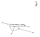
- Fig. 2 shows the in Fig. 1 used LED light source 3 in a market state, according to which the light-emitting surface 4 is covered by a transparent lens 6, referred to as Abdeckmaske. According to the configuration of the lens, the light is emitted in a range of almost 180 ° to the substrate 7 or carrier of the LED light source 3.
Landscapes
- Health & Medical Sciences (AREA)
- Physics & Mathematics (AREA)
- Life Sciences & Earth Sciences (AREA)
- Surgery (AREA)
- Animal Behavior & Ethology (AREA)
- Pathology (AREA)
- Engineering & Computer Science (AREA)
- Biomedical Technology (AREA)
- Heart & Thoracic Surgery (AREA)
- Oral & Maxillofacial Surgery (AREA)
- Medical Informatics (AREA)
- Molecular Biology (AREA)
- General Health & Medical Sciences (AREA)
- Public Health (AREA)
- Veterinary Medicine (AREA)
- Nuclear Medicine, Radiotherapy & Molecular Imaging (AREA)
- General Physics & Mathematics (AREA)
- Optics & Photonics (AREA)
- Radiation-Therapy Devices (AREA)
- Dental Tools And Instruments Or Auxiliary Dental Instruments (AREA)
Description
- Die Erfindung betrifft ein medizinisches Handgerät zur Beleuchtung, insbesondere zur Anwendung in der Ophthalmologie, mit einem als Griffstück dienenden Gehäuse, einer sich vom Gehäuse aus erstreckenden Sonde mit einem darin verlaufenden Lichtleiter und einem endseitigen Lichtauslass, und einer in das Gehäuse integrierten Lichtquelle.
- Medizinische Handgeräte zur Beleuchtung sind aus der Praxis in den unterschiedlichsten Ausführungsformen bekannt. Sofern es sich dabei um Handgeräte zur Anwendung in der Ophthalmologie handelt, ist regelmäßig eine äußerst kleine Bauweise erforderlich. Dies gilt insbesondere für die sich vom Gehäuse aus ersteckende Sonde, die endseitig einen Lichtauslass aufweist. Sofern die Sonde zum Einführen in den menschlichen Körper dient, beispielsweise in das menschliche Auge, ist neben der kleinen Bauweise auch eine ungehinderte Handhabung des Instruments erforderlich.
- Gattungsbildende medizinische Handgeräte, insbesondere zur Anwendung in der Ophthalmologie, sind bspw. aus der
DE 10 2006 051 736 A1 bekannt. Sie bauen äußerst klein und umfassen im Handgriff eine LED-Lichtquelle. Gespeist werden solche Handgeräte entweder über eine im Handgriff befindliche Batterie oder über einen nach außen führenden Stromanschluss, der regelmäßig mit einer Steuereinheit verbunden ist. - Wenngleich LEDs heutzutage eine ganz erhebliche Lichtstärke aufweisen, ist diese noch lange nicht vergleichbar mit herkömmlichen Leuchtmitteln wie bspw. HalogenLampen. Soll die Leuchtdiode zum Einkoppeln von Licht in einen Lichtleiter, bspw. in eine Glasfaser, dienen, treten erhebliche Verluste auf, zumal die LED das Licht extrem streut und nur ein geringer Teil des emittierten Lichts tatsächlich zur Einkopplung in die Glasfaser zur Verfügung steht. Dies macht den Einsatz von LEDs in gattungsbildenden medizinischen Handgeräten problematisch, wenngleich die damit verbundene Miniaturisierung erhebliche Vorteile mit sich bringt.
-
WO 03/021329 - Der vorliegenden Erfindung liegt daher die Aufgabe zugrunde, ein medizinisches Handgerät zur Beleuchtung, insbesondere zur Anwendung in der Ophthalmologie, derart auszugestalten und weiterzubilden, dass unter Nutzung einer geeigneten LED-Lichtquelle mit Konstruktür einfachen Mitteln eine optimale Lichtausbeute und somit eine hinreichend gute Beleuchtung unter Nutzung einer einen Lichtleiter umfassenden Sonde möglich ist.
- Die voranstehende Aufgabe wird erfindungsgemäß durch ein medizinisches Handgerät mit den Merkmalen des Patentanspruchs 1 gelöst. Danach ist das gattungsbildende medizinische Handgerät dadurch gekennzeichnet, dass die Lichtquelle als LED-Lichtquelle mit einer Licht emittierenden Fläche ausgeführt ist und dass der Lichtleiter unmittelbar an die Licht emittierende Fläche angrenzt.
- Es hat sich herausgestellt, dass sich zum Einkoppeln in einen Lichtleiter LED-Lichtquellen mit einer Licht emittierenden Fläche ganz besonders eignen, nämlich dann, wenn der Lichtleiter unmittelbar an die Licht emittierende Fläche angrenzt. Dabei werden nicht etwa LEDs mit sogenannten Bonddrähten in einem sonst üblichen transparenten Abdeckkörper verwendet. Vielmehr geht es hier um den Einsatz von LED-Lichtquellen, die eine Licht emittierende Fläche umfassen, die üblicher Weise mit einer Art Silikonlinse bzw. mit einer Abdeckmaske überzogen ist. Solche LED-Lichtquellen streuen das Licht nahezu um 180°.
- Eine solche LED-Lichtquelle wird - ohne den Abdeckkörper - in idealer Weise zur Einkopplung von Licht in einen Lichtleiter verwendet, nämlich dann, wenn der Lichtleiter unmittelbar an die Licht emittierende Fläche angrenzt, wenn man nämlich den Lichtleiter bündig an die Fläche heranführt. Entsprechend wird das Licht nicht etwa über die sonst übliche Linse gestreut, gelangt vielmehr unmittelbar von der Licht emittierenden Fläche in den Lichtleiter hinein, so dass eine maximale/optimale Lichtausbeute realisierbar ist.
- In vorteilhafter Weise handelt es sich bei der LED-Lichtquelle um einen sogenannten Leuchtchip, wie er bspw. aus der
DE 20 2006 018 846 U1 - für sich gesehen - bekannt ist. Wesentlich ist dabei, dass bei dem Leuchtchip eine Licht emittierende Fläche vorgesehen ist, die - bei entsprechender Ausgestaltung des Leuchtchips - entsprechend der Ausgestaltung des Querschnitts einer Lichtleitfaser als runde Fläche - ausgeführt sein kann. Eine Anpassung der Licht emittierenden Fläche an die Querschnittsfläche des Lichtleiters ist von Vorteil. - Bei dem Lichtleiter kann es sich um eine klassische Lichtleitfaser handeln, vorzugsweise um eine Glasfaser, die sich vom Handgriff des medizinischen Handgeräts durch die Sonde hindurch bis zum offenen Ende der Sonde erstreckt. Dort ist der Lichtaustritt vorgesehen.
- Im Konkreten kann es sich bei dem Lichtleiter um eine Monofaser oder aber auch um ein Faserbündel handeln, je nach Bedarf. Die die Lichtleitfaser beinhaltende Sonde kann geradlinig oder aber auch gebogen ausgeführt sein. Darin ist ein besonderer Vorteil der Lichtleitfaser zu sehen, so dass nahezu beliebige Ausgestaltungen der Sonde denkbar sind.
- Zur optimalen Auskopplung des Lichts in den Lichtleiter ist es von weiterem Vorteil, wenn der Lichtleiter in etwa orthogonal zu der Licht emittierenden Fläche ausgerichtet ist. Grundsätzlich ist es denkbar, dass der Lichtleiter in seiner Position zu der Licht emittierenden Fläche durch entsprechende Halte-/Positionierungs-/Justagemittel gehalten ist.
- Zur besonders einfachen Ausgestaltung der Positionierung des Lichtleiters zur Licht emittierenden Fläche der LED-Lichtquelle ist es von Vorteil, wenn der Lichtleiter des im Anspruch 1 definierten Handgeräts endseitig mit der Licht emittierenden Fläche verklebt ist. Vorzugsweise ist der Lichtleiter mit der Licht emittierenden Fläche bündig verklebt. Bei dem Klebstoff handelt es sich um einen transparenten Klebstoff, der im Bereich der dort entstehenden Wärme temperatur- und alterungsbeständig ist. Eine Anpassung der thermischen Ausdehnungskoeffizienten der unterschiedlichen Materialien ist ebenfalls von Vorteil.
- Im Konkreten ist es denkbar, dass der Klebstoff die Licht emittierende Fläche insgesamt im Sinne einer Abdeckmaske überdeckt, wobei der Lichtleiter zur Kontaktierung mit der Licht emittierenden Fläche in den Klebstoff hineingetaucht wird, und zwar vorzugsweise bis zur vollständigen Kontaktierung der Licht emittierenden Fläche.
- In erfindungsgemäßer Weise ist der über die Querschnittsfläche des Lichtleiters hinausragende Bereich durch eine lichtundurchlässige Abdeckmaske überdeckt, so dass das aus der Fläche heraus emittierte Licht komplett in den Lichtleiter eingekoppelt wird. Ergänzend kann die Licht emittierende Fläche in etwa dem Faserquerschnitt angepasst sein.
- Schließlich ist es von weiterem Vorteil, wenn der Verbindungsbereich zwischen der Lichtleitfaser und der Licht emittierender Fläche optisch und/oder mechanisch versiegelt ist. Unter einer mechanischen Versiegelung ist eine Stabilisierung der Verbindung zu verstehen. Eine optische Versiegelung dient zur Abschottung der Lichtquelle nach außen, so dass das gesamte Licht zur Einkopplung in den Lichtleiter zur Verfügung steht. Die Versiegelung kann im Sinne eines Überzugs hergestellt sein, der die Lichtquelle insgesamt und den Endbereich des Lichtleiters überdeckt und somit auch die Verbindung zwischen der LED-Lichtquelle und dem Lichtleiter begünstigt bzw. stabilisiert.
- Es gibt nun verschiedene Möglichkeiten, die Lehre der vorliegenden Erfindung in vorteilhafter Weise auszugestalten und weiterzubilden. Dazu ist einerseits auf die dem Patentanspruch 1 nachgeordneten Patentansprüche und andererseits auf die nachfolgende Erläuterung eines Ausführungsbeispiels der Erfindung anhand der Zeichnung zu verweisen. In Verbindung mit der Erläuterung des bevorzugten Ausführungsbeispiels der Erfindung anhand der Zeichnung werden auch im Allgemeinen bevorzugte Ausgestaltungen und Weiterbildungen der Lehre erläutert. In der Zeichnung zeigt
- Fig. 1
- in einer schematischen Ansicht ein Ausführungsbeispiel einer Lichtquelle mit Lichteinkopplung in einen Lichtleiter zur Verwendung in einem erfindungsgemäßen medizinischen Handgerät und
- Fig. 2
- die verwendete LED-Lichtquelle in handelsüblicher Form.
-
Fig. 1 zeigt einen Teil des "Innenlebens" eines medizinischen Handgeräts zur Beleuchtung, insbesondere zur Anwendung in der Ophthalmologie, wobei ein solches Handgerät ein in der Figur nicht gezeigtes Gehäuse umfasst, welches üblicher Weise als Griffstück dient. Von dem Gehäuse aus erstreckt sich eine Sonde 1 mit einem darin verlaufenden Lichtleiter 2. Bei dem Lichtleiter 2 handelt es sich bspw., jedoch nicht zwingend, um eine Monofaser aus Glas. - Des Weiteren ist eine in das nicht gezeigte Gehäuse integrierte LED-Lichtquelle 3 vorgesehen, deren Licht in den Lichtleiter 2 eingekoppelt wird. Einer einfachen Darstellung halber sind die elektrischen Anschlüsse der LED-Lichtquelle sowie die Stromversorgung nicht gezeigt, zumal es bei der beanspruchten Lehre darauf nicht ankommt.
- Bei dem Lichtleiter 2 kann es sich grundsätzlich auch um ein Faserbündel handeln. Bei der Verwendung von Monofasern sind beim Einsatz in der Ophthalmologie Faserquerschnitte von 20 bis 25 Gage von Vorteil.
-
Fig. 1 lässt des Weiteren erkennen, dass die LED-Lichtquelle 3 eine Licht emittierende Fläche 4 aufweist. Im Bereich der Licht emittierenden Fläche 4 ist der Lichtleiter 2, genauer gesagt die Monofaser, an die Licht emittierende Fläche angekoppelt, so dass das emittierte Licht der LED-Lichtquelle 3 unmittelbar in den Lichtleiter 2 eingespeist wird. - Die Verbindung zwischen der LED-Lichtquelle 3 bzw. der Licht emittierenden Fläche 4 und dem Lichtleiter 2 ist durch einen transparenten Klebstoff 5 bewerkstelligt.
-
Fig. 2 zeigt die inFig. 1 verwendete LED-Lichtquelle 3 in einem marktüblichen Zustand, wonach die Licht emittierende Fläche 4 durch eine transparente Linse 6, als Abdeckmaske bezeichnet, überdeckt ist. Entsprechend der Ausgestaltung der Linse wird das Licht in einem Bereich von nahezu 180° zum Substrat 7 bzw. Träger der LED-Lichtquelle 3 emittiert. - Schließlich sei angemerkt, dass das voranstehend erörterte Ausführungsbeispiel lediglich der beispielhaften Erörterung des erfindungsgemäßen medizinischen Handgeräts dient, dieses jedoch nicht auf das Ausführungsbeispiel einschränkt.
-
- 1
- Sonde
- 2
- Lichtleiter
- 3
- LED-Lichtquelle
- 4
- Licht emittierende Fläche (von 3)
- 5
- Klebstoff
- 6
- Linse
- 7
- Substrat
Claims (13)
- Medizinisches Handgerät zur Beleuchtung, insbesondere zur Anwendung in der Ophthalmologie, mit einem als Griffstück dienenden Gehäuse, einer sich vom Gehäuse aus erstreckenden Sonde (1) mit einem darin verlaufenden Lichtleiter (2) und einem endseitigen Lichtauslass, und einer in das Gehäuse integrierten Lichtquelle (3),
wobei die Lichtquelle (3) als LED-Lichtquelle mit einer Licht emittierenden Fläche (4) ausgeführt ist, wobei der Lichtleiter (2) unmittelbar an die Licht emittierende Fläche (4) angrenzt und wobei der Lichtleiter (2) endseitig mit der Licht emittierenden Fläche (4) verklebt ist,
dadurch gekennzeichnet, dass der über die Querschnittsfläche des Lichtleiters (2) hinausragende Bereich der Licht emittierenden Fläche durch eine lichtundurchlässige Abdeckmaske überdeckt ist, so dass das aus der Fläche heraus emittierte Licht komplett in den Lichtleiter eingekoppelt wird. - Handgerät nach Anspruch 1, dadurch gekennzeichnet, dass die Lichtquelle (3) als Leuchtchip ausgeführt ist.
- Handgerät nach Anspruch 1 oder 2, dadurch gekennzeichnet, dass der Lichtleiter (2) als Lichtleitfaser, vorzugsweise als Glasfaser, ausgeführt ist.
- Handgerät nach Anspruch 3, dadurch gekennzeichnet, dass der Lichtleiter (2) als Monofaser ausgeführt ist.
- Handgerät nach Anspruch 3, dadurch gekennzeichnet, dass der Lichtleiter (2) als Faserbündel ausgeführt ist.
- Handgerät nach einem der Ansprüche 1 bis 5, dadurch gekennzeichnet, dass der Lichtleiter (2) in etwa orthogonal zu der Licht emittierenden Fläche (4) ausgerichtet ist.
- Handgerät nach einem der Ansprüche 1 bis 6, dadurch gekennzeichnet, dass der Lichtleiter (2) mit mindestens einer planen Fläche an die Licht emittierende Fläche (4) angrenzt.
- Handgerät nach einem der Ansprüche 1 bis 7, dadurch gekennzeichnet, dass der Lichtleiter (2) - endseitig - mit der Licht emittierenden Fläche (4) bündig verklebt ist.
- Handgerät nach Anspruch 8, dadurch gekennzeichnet, dass der Lichtleiter (2) mittels transparentem Klebstoff (5) mit der Licht emittierenden Fläche (4) verklebt ist.
- Handgerät nach Anspruch 8 oder 9, dadurch gekennzeichnet, dass der Klebstoff (5) die Licht emittierende Fläche (4) insgesamt im Sinne einer Abdeckmaske - anstelle eines Linsenkörpers - überdeckt.
- Handgerät nach Anspruch 10, dadurch gekennzeichnet, dass der über die Querschnittsfläche des Lichtleiters (2) hinausragende Bereich der Abdeckmaske zumindest weitgehend lichtundurchlässig ist.
- Handgerät nach einem der Ansprüche 8 bis 11, dadurch gekennzeichnet, dass die Licht emittierenden Fläche (4) in etwa dem Faserquerschnitt angepasst ist.
- Handgerät nach einem der Ansprüche 1 bis 12, dadurch gekennzeichnet, dass der Verbindungsbereich zwischen Lichtleitfaser (2) und Licht emittierender Fläche (4) optisch und/oder mechanisch versiegelt ist.
Applications Claiming Priority (2)
| Application Number | Priority Date | Filing Date | Title |
|---|---|---|---|
| DE102009030060A DE102009030060A1 (de) | 2009-06-22 | 2009-06-22 | Medizinisches Handgerät zur Beleuchtung |
| PCT/DE2010/000697 WO2010149136A1 (de) | 2009-06-22 | 2010-06-21 | Medizinisches handgerät zur beleuchtung |
Publications (2)
| Publication Number | Publication Date |
|---|---|
| EP2387369A1 EP2387369A1 (de) | 2011-11-23 |
| EP2387369B1 true EP2387369B1 (de) | 2014-09-03 |
Family
ID=42967836
Family Applications (1)
| Application Number | Title | Priority Date | Filing Date |
|---|---|---|---|
| EP10739292.0A Not-in-force EP2387369B1 (de) | 2009-06-22 | 2010-06-21 | Medizinisches handgerät zur beleuchtung |
Country Status (4)
| Country | Link |
|---|---|
| US (1) | US20120176584A1 (de) |
| EP (1) | EP2387369B1 (de) |
| DE (1) | DE102009030060A1 (de) |
| WO (1) | WO2010149136A1 (de) |
Family Cites Families (9)
| Publication number | Priority date | Publication date | Assignee | Title |
|---|---|---|---|---|
| JPS57102077A (en) * | 1980-12-16 | 1982-06-24 | Mitsubishi Electric Corp | Photo coupling device by photo semiconductor element and optical fiber |
| US4946242A (en) * | 1987-08-28 | 1990-08-07 | Hitachi, Ltd. | Optical part including integral combination of optical fiber and light emitting or receiving element and method of manufacturing the same |
| DE3834395A1 (de) * | 1988-10-10 | 1990-04-12 | Telefunken Electronic Gmbh | Kopplungsvorrichtung einer optischen faser mit einer lichtemittierenden diode |
| DE10065624C2 (de) * | 2000-12-29 | 2002-11-14 | Hans Kragl | Kopplungsanordnung zum optischen Koppeln eines Lichtwellenleiters mit einem elektro-optischen oder opto-elektrischen Halbleiterwandler |
| US6921920B2 (en) * | 2001-08-31 | 2005-07-26 | Smith & Nephew, Inc. | Solid-state light source |
| WO2006034171A1 (en) * | 2004-09-17 | 2006-03-30 | Optim, Inc. | Methods of mounting an led endoscope illuminator within an endoscope |
| EP1813344B1 (de) | 2004-11-15 | 2014-08-13 | JX Nippon Mining & Metals Corporation | Wasserstoffabtrennmembran, sputtertarget zur bildung einer wasserstoffabtrennmembran und herstellungsverfahren dafür |
| TWM307194U (en) | 2006-06-29 | 2007-03-01 | Shr-Fu Huang | Structure of light emitting diode (LED) |
| DE102006051736A1 (de) | 2006-10-30 | 2008-05-08 | Geuder Ag | Medizinisches Handgerät zur Beleuchtung |
-
2009
- 2009-06-22 DE DE102009030060A patent/DE102009030060A1/de not_active Withdrawn
-
2010
- 2010-06-21 US US13/379,904 patent/US20120176584A1/en not_active Abandoned
- 2010-06-21 WO PCT/DE2010/000697 patent/WO2010149136A1/de not_active Ceased
- 2010-06-21 EP EP10739292.0A patent/EP2387369B1/de not_active Not-in-force
Also Published As
| Publication number | Publication date |
|---|---|
| EP2387369A1 (de) | 2011-11-23 |
| WO2010149136A1 (de) | 2010-12-29 |
| US20120176584A1 (en) | 2012-07-12 |
| DE102009030060A1 (de) | 2011-01-05 |
Similar Documents
| Publication | Publication Date | Title |
|---|---|---|
| DE102014020012B4 (de) | Vorrichtung zur optischen Vermessung von Fluoreszenzeigenschaften eines Objekts mit überlagerter Kompensationslichtquelle und wellenselektivem Empfangspfad | |
| EP2336818A1 (de) | Endoskopisches System mit fasergepumpter Fluoreszenzbeleuchtung | |
| WO2012123233A2 (de) | Leuchtvorrichtung | |
| EP2591502B1 (de) | Leuchtdiode | |
| EP3321592A1 (de) | Kochgerät mit lichtelementen | |
| DE112007000773T5 (de) | Licht emittierende Vorrichtung | |
| EP2594188A1 (de) | Medizinisches Endoskop mit einer Kühlvorrichtung | |
| DE102018207071B4 (de) | Bedien- und/oder Anzeigeelement für ein Kraftfahrzeug | |
| DE102007063262A1 (de) | Beleuchtungsvorrichtung zum Erzeugen von Licht und zum Einkoppeln des Lichts in ein proximales Ende eines Lichtleitkabels einer Beobachtungsvorrichtung für die Endoskopie oder Mikroskopie | |
| DE102012107578B4 (de) | Optoelektronisches Bauelement und Verfahren zur Herstellung eines optoelektronischen Bauelements sowie Messvorrichtung mit einem lichtemittierenden, optoelektronischen Bauelement | |
| DE102014106074A1 (de) | Leuchtvorrichtung und Verfahren zum Herstellen einer Leuchtvorrichtung | |
| WO2018015399A1 (de) | Leuchtvorrichtung für ein mobiles endgerät | |
| DE102008038748A1 (de) | Oberflächenmontierbares, optoelektronisches Halbleiterbauteil | |
| DE102007040596A1 (de) | Beleuchtungsmittel mit Wärmespreizung durch Wärmeleitbeschichtung | |
| DE102004047640A1 (de) | Optoelektronisches Bauelement und Gehäuse für ein optoelektronisches Bauelement | |
| DE102010042619A1 (de) | Leuchtvorrichtung zur flächigen Lichtabstrahlung | |
| DE102009037625A1 (de) | Beleuchtungseinrichtung für ein Kraftfahrzeug | |
| DE102017218207A1 (de) | Beleuchtungsvorrichtung | |
| DE102013222481A1 (de) | Optisches Element für eine Leuchte, sowie Leuchte | |
| WO2010149136A1 (de) | Medizinisches handgerät zur beleuchtung | |
| DE102008016675A1 (de) | Leuchtanordnung mit einem Lichtleiter und Leuchtdioden | |
| DE10228390B4 (de) | Optokoppler | |
| DE102009049057B4 (de) | LED-Modul, Verfahren zum Betreiben dieses LED-Moduls und Beleuchtungsvorrichtung mit diesem LED-Modul | |
| DE102021121194A1 (de) | Lichtquellenvorrichtung | |
| DE202010010799U1 (de) | Beleuchtungsvorrichtung |
Legal Events
| Date | Code | Title | Description |
|---|---|---|---|
| PUAI | Public reference made under article 153(3) epc to a published international application that has entered the european phase |
Free format text: ORIGINAL CODE: 0009012 |
|
| 17P | Request for examination filed |
Effective date: 20110729 |
|
| AK | Designated contracting states |
Kind code of ref document: A1 Designated state(s): AL AT BE BG CH CY CZ DE DK EE ES FI FR GB GR HR HU IE IS IT LI LT LU LV MC MK MT NL NO PL PT RO SE SI SK SM TR |
|
| DAX | Request for extension of the european patent (deleted) | ||
| 17Q | First examination report despatched |
Effective date: 20130905 |
|
| GRAP | Despatch of communication of intention to grant a patent |
Free format text: ORIGINAL CODE: EPIDOSNIGR1 |
|
| INTG | Intention to grant announced |
Effective date: 20140225 |
|
| GRAS | Grant fee paid |
Free format text: ORIGINAL CODE: EPIDOSNIGR3 |
|
| GRAA | (expected) grant |
Free format text: ORIGINAL CODE: 0009210 |
|
| AK | Designated contracting states |
Kind code of ref document: B1 Designated state(s): AL AT BE BG CH CY CZ DE DK EE ES FI FR GB GR HR HU IE IS IT LI LT LU LV MC MK MT NL NO PL PT RO SE SI SK SM TR |
|
| REG | Reference to a national code |
Ref country code: GB Ref legal event code: FG4D Free format text: NOT ENGLISH |
|
| REG | Reference to a national code |
Ref country code: CH Ref legal event code: EP Ref country code: AT Ref legal event code: REF Ref document number: 685138 Country of ref document: AT Kind code of ref document: T Effective date: 20140915 |
|
| REG | Reference to a national code |
Ref country code: IE Ref legal event code: FG4D Free format text: LANGUAGE OF EP DOCUMENT: GERMAN |
|
| REG | Reference to a national code |
Ref country code: DE Ref legal event code: R096 Ref document number: 502010007808 Country of ref document: DE Effective date: 20141016 |
|
| REG | Reference to a national code |
Ref country code: NL Ref legal event code: T3 |
|
| PG25 | Lapsed in a contracting state [announced via postgrant information from national office to epo] |
Ref country code: NO Free format text: LAPSE BECAUSE OF FAILURE TO SUBMIT A TRANSLATION OF THE DESCRIPTION OR TO PAY THE FEE WITHIN THE PRESCRIBED TIME-LIMIT Effective date: 20141203 Ref country code: GR Free format text: LAPSE BECAUSE OF FAILURE TO SUBMIT A TRANSLATION OF THE DESCRIPTION OR TO PAY THE FEE WITHIN THE PRESCRIBED TIME-LIMIT Effective date: 20141204 Ref country code: SE Free format text: LAPSE BECAUSE OF FAILURE TO SUBMIT A TRANSLATION OF THE DESCRIPTION OR TO PAY THE FEE WITHIN THE PRESCRIBED TIME-LIMIT Effective date: 20140903 Ref country code: FI Free format text: LAPSE BECAUSE OF FAILURE TO SUBMIT A TRANSLATION OF THE DESCRIPTION OR TO PAY THE FEE WITHIN THE PRESCRIBED TIME-LIMIT Effective date: 20140903 Ref country code: LT Free format text: LAPSE BECAUSE OF FAILURE TO SUBMIT A TRANSLATION OF THE DESCRIPTION OR TO PAY THE FEE WITHIN THE PRESCRIBED TIME-LIMIT Effective date: 20140903 |
|
| REG | Reference to a national code |
Ref country code: LT Ref legal event code: MG4D |
|
| PG25 | Lapsed in a contracting state [announced via postgrant information from national office to epo] |
Ref country code: LV Free format text: LAPSE BECAUSE OF FAILURE TO SUBMIT A TRANSLATION OF THE DESCRIPTION OR TO PAY THE FEE WITHIN THE PRESCRIBED TIME-LIMIT Effective date: 20140903 Ref country code: HR Free format text: LAPSE BECAUSE OF FAILURE TO SUBMIT A TRANSLATION OF THE DESCRIPTION OR TO PAY THE FEE WITHIN THE PRESCRIBED TIME-LIMIT Effective date: 20140903 Ref country code: CY Free format text: LAPSE BECAUSE OF FAILURE TO SUBMIT A TRANSLATION OF THE DESCRIPTION OR TO PAY THE FEE WITHIN THE PRESCRIBED TIME-LIMIT Effective date: 20140903 |
|
| PG25 | Lapsed in a contracting state [announced via postgrant information from national office to epo] |
Ref country code: RO Free format text: LAPSE BECAUSE OF FAILURE TO SUBMIT A TRANSLATION OF THE DESCRIPTION OR TO PAY THE FEE WITHIN THE PRESCRIBED TIME-LIMIT Effective date: 20140903 Ref country code: IS Free format text: LAPSE BECAUSE OF FAILURE TO SUBMIT A TRANSLATION OF THE DESCRIPTION OR TO PAY THE FEE WITHIN THE PRESCRIBED TIME-LIMIT Effective date: 20150103 Ref country code: SK Free format text: LAPSE BECAUSE OF FAILURE TO SUBMIT A TRANSLATION OF THE DESCRIPTION OR TO PAY THE FEE WITHIN THE PRESCRIBED TIME-LIMIT Effective date: 20140903 Ref country code: PT Free format text: LAPSE BECAUSE OF FAILURE TO SUBMIT A TRANSLATION OF THE DESCRIPTION OR TO PAY THE FEE WITHIN THE PRESCRIBED TIME-LIMIT Effective date: 20150105 Ref country code: EE Free format text: LAPSE BECAUSE OF FAILURE TO SUBMIT A TRANSLATION OF THE DESCRIPTION OR TO PAY THE FEE WITHIN THE PRESCRIBED TIME-LIMIT Effective date: 20140903 Ref country code: CZ Free format text: LAPSE BECAUSE OF FAILURE TO SUBMIT A TRANSLATION OF THE DESCRIPTION OR TO PAY THE FEE WITHIN THE PRESCRIBED TIME-LIMIT Effective date: 20140903 |
|
| PG25 | Lapsed in a contracting state [announced via postgrant information from national office to epo] |
Ref country code: PL Free format text: LAPSE BECAUSE OF FAILURE TO SUBMIT A TRANSLATION OF THE DESCRIPTION OR TO PAY THE FEE WITHIN THE PRESCRIBED TIME-LIMIT Effective date: 20140903 |
|
| REG | Reference to a national code |
Ref country code: DE Ref legal event code: R097 Ref document number: 502010007808 Country of ref document: DE |
|
| PLBE | No opposition filed within time limit |
Free format text: ORIGINAL CODE: 0009261 |
|
| STAA | Information on the status of an ep patent application or granted ep patent |
Free format text: STATUS: NO OPPOSITION FILED WITHIN TIME LIMIT |
|
| PG25 | Lapsed in a contracting state [announced via postgrant information from national office to epo] |
Ref country code: DK Free format text: LAPSE BECAUSE OF FAILURE TO SUBMIT A TRANSLATION OF THE DESCRIPTION OR TO PAY THE FEE WITHIN THE PRESCRIBED TIME-LIMIT Effective date: 20140903 |
|
| 26N | No opposition filed |
Effective date: 20150604 |
|
| PG25 | Lapsed in a contracting state [announced via postgrant information from national office to epo] |
Ref country code: SI Free format text: LAPSE BECAUSE OF FAILURE TO SUBMIT A TRANSLATION OF THE DESCRIPTION OR TO PAY THE FEE WITHIN THE PRESCRIBED TIME-LIMIT Effective date: 20140903 |
|
| PG25 | Lapsed in a contracting state [announced via postgrant information from national office to epo] |
Ref country code: MC Free format text: LAPSE BECAUSE OF FAILURE TO SUBMIT A TRANSLATION OF THE DESCRIPTION OR TO PAY THE FEE WITHIN THE PRESCRIBED TIME-LIMIT Effective date: 20140903 |
|
| PG25 | Lapsed in a contracting state [announced via postgrant information from national office to epo] |
Ref country code: LU Free format text: LAPSE BECAUSE OF FAILURE TO SUBMIT A TRANSLATION OF THE DESCRIPTION OR TO PAY THE FEE WITHIN THE PRESCRIBED TIME-LIMIT Effective date: 20150621 |
|
| REG | Reference to a national code |
Ref country code: IE Ref legal event code: MM4A |
|
| PG25 | Lapsed in a contracting state [announced via postgrant information from national office to epo] |
Ref country code: IE Free format text: LAPSE BECAUSE OF NON-PAYMENT OF DUE FEES Effective date: 20150621 |
|
| REG | Reference to a national code |
Ref country code: FR Ref legal event code: PLFP Year of fee payment: 7 |
|
| PG25 | Lapsed in a contracting state [announced via postgrant information from national office to epo] |
Ref country code: MT Free format text: LAPSE BECAUSE OF FAILURE TO SUBMIT A TRANSLATION OF THE DESCRIPTION OR TO PAY THE FEE WITHIN THE PRESCRIBED TIME-LIMIT Effective date: 20140903 |
|
| PG25 | Lapsed in a contracting state [announced via postgrant information from national office to epo] |
Ref country code: HU Free format text: LAPSE BECAUSE OF FAILURE TO SUBMIT A TRANSLATION OF THE DESCRIPTION OR TO PAY THE FEE WITHIN THE PRESCRIBED TIME-LIMIT; INVALID AB INITIO Effective date: 20100621 Ref country code: BG Free format text: LAPSE BECAUSE OF FAILURE TO SUBMIT A TRANSLATION OF THE DESCRIPTION OR TO PAY THE FEE WITHIN THE PRESCRIBED TIME-LIMIT Effective date: 20140903 Ref country code: SM Free format text: LAPSE BECAUSE OF FAILURE TO SUBMIT A TRANSLATION OF THE DESCRIPTION OR TO PAY THE FEE WITHIN THE PRESCRIBED TIME-LIMIT Effective date: 20140903 |
|
| REG | Reference to a national code |
Ref country code: FR Ref legal event code: PLFP Year of fee payment: 8 |
|
| PG25 | Lapsed in a contracting state [announced via postgrant information from national office to epo] |
Ref country code: ES Free format text: LAPSE BECAUSE OF FAILURE TO SUBMIT A TRANSLATION OF THE DESCRIPTION OR TO PAY THE FEE WITHIN THE PRESCRIBED TIME-LIMIT Effective date: 20140903 |
|
| PG25 | Lapsed in a contracting state [announced via postgrant information from national office to epo] |
Ref country code: TR Free format text: LAPSE BECAUSE OF FAILURE TO SUBMIT A TRANSLATION OF THE DESCRIPTION OR TO PAY THE FEE WITHIN THE PRESCRIBED TIME-LIMIT Effective date: 20140903 |
|
| REG | Reference to a national code |
Ref country code: FR Ref legal event code: PLFP Year of fee payment: 9 |
|
| PG25 | Lapsed in a contracting state [announced via postgrant information from national office to epo] |
Ref country code: MK Free format text: LAPSE BECAUSE OF FAILURE TO SUBMIT A TRANSLATION OF THE DESCRIPTION OR TO PAY THE FEE WITHIN THE PRESCRIBED TIME-LIMIT Effective date: 20140903 |
|
| PG25 | Lapsed in a contracting state [announced via postgrant information from national office to epo] |
Ref country code: AL Free format text: LAPSE BECAUSE OF FAILURE TO SUBMIT A TRANSLATION OF THE DESCRIPTION OR TO PAY THE FEE WITHIN THE PRESCRIBED TIME-LIMIT Effective date: 20140903 |
|
| PGFP | Annual fee paid to national office [announced via postgrant information from national office to epo] |
Ref country code: NL Payment date: 20190619 Year of fee payment: 10 Ref country code: IT Payment date: 20190619 Year of fee payment: 10 |
|
| PGFP | Annual fee paid to national office [announced via postgrant information from national office to epo] |
Ref country code: FR Payment date: 20190626 Year of fee payment: 10 Ref country code: BE Payment date: 20190619 Year of fee payment: 10 |
|
| PGFP | Annual fee paid to national office [announced via postgrant information from national office to epo] |
Ref country code: CH Payment date: 20190624 Year of fee payment: 10 |
|
| PGFP | Annual fee paid to national office [announced via postgrant information from national office to epo] |
Ref country code: GB Payment date: 20190624 Year of fee payment: 10 Ref country code: AT Payment date: 20190618 Year of fee payment: 10 |
|
| REG | Reference to a national code |
Ref country code: CH Ref legal event code: PL |
|
| REG | Reference to a national code |
Ref country code: NL Ref legal event code: MM Effective date: 20200701 |
|
| REG | Reference to a national code |
Ref country code: AT Ref legal event code: MM01 Ref document number: 685138 Country of ref document: AT Kind code of ref document: T Effective date: 20200621 |
|
| GBPC | Gb: european patent ceased through non-payment of renewal fee |
Effective date: 20200621 |
|
| REG | Reference to a national code |
Ref country code: BE Ref legal event code: MM Effective date: 20200630 |
|
| PG25 | Lapsed in a contracting state [announced via postgrant information from national office to epo] |
Ref country code: LI Free format text: LAPSE BECAUSE OF NON-PAYMENT OF DUE FEES Effective date: 20200630 Ref country code: CH Free format text: LAPSE BECAUSE OF NON-PAYMENT OF DUE FEES Effective date: 20200630 Ref country code: NL Free format text: LAPSE BECAUSE OF NON-PAYMENT OF DUE FEES Effective date: 20200701 Ref country code: GB Free format text: LAPSE BECAUSE OF NON-PAYMENT OF DUE FEES Effective date: 20200621 Ref country code: FR Free format text: LAPSE BECAUSE OF NON-PAYMENT OF DUE FEES Effective date: 20200630 |
|
| PG25 | Lapsed in a contracting state [announced via postgrant information from national office to epo] |
Ref country code: AT Free format text: LAPSE BECAUSE OF NON-PAYMENT OF DUE FEES Effective date: 20200621 Ref country code: BE Free format text: LAPSE BECAUSE OF NON-PAYMENT OF DUE FEES Effective date: 20200630 |
|
| PG25 | Lapsed in a contracting state [announced via postgrant information from national office to epo] |
Ref country code: IT Free format text: LAPSE BECAUSE OF NON-PAYMENT OF DUE FEES Effective date: 20200621 |
|
| P01 | Opt-out of the competence of the unified patent court (upc) registered |
Effective date: 20230525 |
|
| PGFP | Annual fee paid to national office [announced via postgrant information from national office to epo] |
Ref country code: DE Payment date: 20230821 Year of fee payment: 14 |
|
| REG | Reference to a national code |
Ref country code: DE Ref legal event code: R119 Ref document number: 502010007808 Country of ref document: DE |
|
| PG25 | Lapsed in a contracting state [announced via postgrant information from national office to epo] |
Ref country code: DE Free format text: LAPSE BECAUSE OF NON-PAYMENT OF DUE FEES Effective date: 20250101 |