EP2386450A2 - Tyre cleaning device - Google Patents
Tyre cleaning device Download PDFInfo
- Publication number
- EP2386450A2 EP2386450A2 EP11166270A EP11166270A EP2386450A2 EP 2386450 A2 EP2386450 A2 EP 2386450A2 EP 11166270 A EP11166270 A EP 11166270A EP 11166270 A EP11166270 A EP 11166270A EP 2386450 A2 EP2386450 A2 EP 2386450A2
- Authority
- EP
- European Patent Office
- Prior art keywords
- tire
- cleaning
- claws
- cleaning device
- holding
- Prior art date
- Legal status (The legal status is an assumption and is not a legal conclusion. Google has not performed a legal analysis and makes no representation as to the accuracy of the status listed.)
- Withdrawn
Links
Images

Classifications
-
- B—PERFORMING OPERATIONS; TRANSPORTING
- B60—VEHICLES IN GENERAL
- B60S—SERVICING, CLEANING, REPAIRING, SUPPORTING, LIFTING, OR MANOEUVRING OF VEHICLES, NOT OTHERWISE PROVIDED FOR
- B60S1/00—Cleaning of vehicles
- B60S1/62—Other vehicle fittings for cleaning
- B60S1/66—Other vehicle fittings for cleaning for cleaning vehicle exterior
- B60S1/68—Other vehicle fittings for cleaning for cleaning vehicle exterior for freeing wheels or tyres from foreign matter, e.g. wheel scrapers
Definitions
- the invention relates to a cleaning device for tires, in particular for tires of tractors, self-propelled machines, as well as trailers that are used off the roads, such as on agricultural land.
- the wheels of these machines usually consist of rubber tires with a profile of up to 10 cm depth.
- the present invention is based on the object to provide a cleaning device that can be firmly attached, for example, to a tractor, to a self-propelled machine, to a truck, or to a trailer.
- the cleaning device should, if necessary, be switched on to remove adhering soil and dirt from the tires before these roads, paths, etc. happen.
- the cleaning device is advantageously on the vehicle, such as tractors, self-propelled machine, trailer, etc. permanently attached and is thus always available. It is switchable while driving and does not cause a significant delay in work processes.
- the cleaning device according to the invention comprises cleaning claws which are arranged next to one another like a comb over the tire, advantageously over its entire width or at least in such a way that it is possible to clean the tire over its entire width.
- the claws are particularly preferably made of spring steel. Both round steel and flat steel are suitable.
- the claws are connected together by a holding package and arranged parallel to each other at a distance of about 2-5 cm.
- the holding package is connected via a hinge on the support frame.
- the claws are pressed over the holding package to the tire surface when driving forward.
- the pressing of the holding package is preferably carried out hydraulically or pneumatically by a lifting cylinder, which is attached to the holding frame and pressure on the holding package.
- a lifting cylinder which is attached to the holding frame and pressure on the holding package.
- the cleaning claws must be switched on in good time before the wheels pass the road. During the cleaning process, the vehicle should be moved forward at about walking pace so that the claws have enough time to adapt to the tire profile.
- the claws are again switched away from the tire profile via the hydraulically controlled holding package.
- the cleaning claws are designed so that they have space in the off state under the fender and thus can lead to any impairment of vehicle use.
- a preferred embodiment of the cleaning device is in the Figures 1-3 shown schematically.
- FIG. 1 shows the schematic representation of the side view of a tire 6, for example, a tractor tire, with studs 7.
- a tire 6 for example, a tractor tire, with studs 7.
- Above the tire 6 is a plurality of juxtaposed cleaning claws 1 (see FIG. 3 ) arranged.
- the cleaning claws 1 are held by a holding packet 2 in a row next to each other above the tire and tensioned by means of a holding frame 3, a swivel joint 4 and a pressure cylinder 5 on the tire 6.
- the holding package 2 is attached via a hinge 4 on the support frame 3.
- the cleaning device comprising cleaning claws, holding package, holding frame, swivel joint and impression cylinder are fastened to the vehicle and are preferably arranged below the respective mudguard.
- FIG. 2 shows a further schematic representation of the side view of a tire 6 with cleaning device, wherein a cleaning claw 1 is located in a trough between two studs 7.
- the cleaning claws 1 are stretched in the switched state of the cleaning system on the tire surface that they are pressed while driving forward in the troughs between the studs and scraping dirt adhering to the tire.
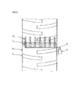
- FIG. 3 shows a schematic representation of a plan view of the tire with cleaning device according to FIG. 1 ,
- the cleaning claws 1 are arranged in a comb-like manner over the tire 6 via the holding packet 2.
- the holding package is about 3 - 5 cm narrower than the tire. This prevents damage.
Landscapes
- Engineering & Computer Science (AREA)
- Mechanical Engineering (AREA)
- Tires In General (AREA)
- Vehicle Cleaning, Maintenance, Repair, Refitting, And Outriggers (AREA)
Abstract
Description
Die Erfindung bezieht sich auf eine Reinigungsvorrichtung für Reifen, insbesondere für Reifen von Zugmaschinen, selbstfahrenden Arbeitsmaschinen, sowie Anhänger, die abseits von Straßen, wie zum Beispiel auf landwirtschaftlichen Flächen zum Einsatz kommen.The invention relates to a cleaning device for tires, in particular for tires of tractors, self-propelled machines, as well as trailers that are used off the roads, such as on agricultural land.
Die Räder dieser Maschinen bestehen in der Regel aus Gummireifen mit einem Profil von bis zu 10 cm Tiefe.The wheels of these machines usually consist of rubber tires with a profile of up to 10 cm depth.
Im Einsatz auf landwirtschaftlichen Flächen, sowie bei Bauarbeiten auf nicht abgetrockneten Böden tritt das Problem auf, dass Erde und Schmutz am Reifenprofil anhaften. Bei der Fahrt auf Straßen oder Wegen löst sich dies Verschmutzung und führt zu Verunreinigung von Straßen, Wegen und Plätzen. Dies stellt eine Gefährdung für andere Verkehrsteilnehmer dar. Laut Straßenverkehrsordnung sind verschmutzte Fahrbahnen unmittelbar vom Verursacher zu reinigen. In der Praxis tritt oft der Fall ein, dass ein Reinigen der Straße oft gar nicht oder verspätet durchgeführt wird. Dadurch entsteht für den Verursacher ein nicht unerhebliches Risiko, einen Unfall schuldhaft mit zu verursachen. Besonders in den Herbstmonaten, wenn Landwirte die Silomaisernte, Bodenbearbeitung und Feldbestellung durchführen, sind sehr of verschmutzte Straßen anzutreffen.When used on agricultural land, as well as on construction work on undried soils, the problem arises that earth and dirt adhere to the tire tread. When driving on roads or paths, this dissolves pollution and leads to contamination of roads, paths and squares. This poses a danger to other road users. According to road traffic regulations, polluted lanes are to be cleaned directly by the polluter. In practice, there is often the case that cleaning of the road is often not performed or delayed. This creates a significant risk for the polluter to culpably contribute to an accident. Especially in the autumn months, when farmers carry out the silo maize harvest, tillage and field cropping, they are very likely to encounter polluted roads.
Ähnliche Probleme treten sowohl im Hochbau wie im Tiefbau auf. Lastkraftwagen und Baumaschinen verschmutzen z.B. bei Aushubarbeiten, oder Transportfahrten bei feuchter Witterung öffentliche Straßen.Similar problems occur in both structural engineering and civil engineering. Lorries and construction machines pollute e.g. in the case of excavation work, or transportation in humid weather public roads.
Vorrichtungen, die Reifenprofile von Schmutz befreien, bevor sie öffentliche Straßen passieren, gibt es als stationäre Anlagen. Diese haben den Nachteil, dass sie aufwendig zu transportieren sind. Dennoch sind sie z. B. im Bau durchaus einsetzbar.Devices that remove dirt from tire profiles before they pass public roads are stationary installations. These have the disadvantage that they are expensive to transport. Nevertheless, they are z. B. quite suitable in construction.
In der Landwirtschaft sind stationäre Reinigungsanlagen für Reifen nicht geeignet, da sie zu wenig mobil sind.In agriculture stationary tire cleaning systems are not suitable because they are not very mobile.
Der vorliegenden Erfindung liegt die Aufgabe zu Grunde, eine Reinigungsvorrichtung zu schaffen, die beispielsweise an einen Schlepper, an einer selbstfahrenden Arbeitsmaschine, an einem Lkw, oder an einen Anhänger fest angebaut werden kann. Idealerweise soll sich die Reinigungsvorrichtung bedarfsweise zuschalten lassen, um anhaftende Erde und Schmutz von den Reifen zu entfernen, bevor diese Straßen, Wege etc. passieren.The present invention is based on the object to provide a cleaning device that can be firmly attached, for example, to a tractor, to a self-propelled machine, to a truck, or to a trailer. Ideally, the cleaning device should, if necessary, be switched on to remove adhering soil and dirt from the tires before these roads, paths, etc. happen.
Diese Aufgabe wird durch eine Reinigungsvorrichtung mit den Merkmalen des Schutzanspruches 1 gelöst. Vorteilhafte Weiterbildungen sind Gegenstand von Unteransprüchen.This object is achieved by a cleaning device with the features of the protection claim 1. Advantageous developments are the subject of dependent claims.
Der Offenbarungsgehalt der Patentansprüche wird durch Rückbezug auf diese in die Beschreibung aufgenommen.The disclosure of the claims is incorporated by reference to these in the description.
Die Reinigungsvorrichtung ist vorteilhafterweise am Fahrzeug, wie beispielsweise Schlepper, selbstfahrende Arbeitsmaschine, Anhänger etc. fest angebaut und ist somit immer verfügbar. Sie ist während der Fahrt zuschaltbar und verursacht keine wesentliche Verzögerung von Arbeitsabläufen.The cleaning device is advantageously on the vehicle, such as tractors, self-propelled machine, trailer, etc. permanently attached and is thus always available. It is switchable while driving and does not cause a significant delay in work processes.
Die Reinigungsvorrichtung gemäß der Erfindung umfasst Reinigungskrallen, die nebeneinander kammartig über dem Reifen angeordnet sind, vorteilhafterweise über dessen gesamte Breite oder zumindest derart, dass eine Reinigung des Reifens über dessen gesamte Breite möglich ist.The cleaning device according to the invention comprises cleaning claws which are arranged next to one another like a comb over the tire, advantageously over its entire width or at least in such a way that it is possible to clean the tire over its entire width.
Die Krallen sind besonders bevorzugt aus Federstahl gefertigt. Dabei ist sowohl Rundstahl als auch Flachstahl geeignet.The claws are particularly preferably made of spring steel. Both round steel and flat steel are suitable.
Die Krallen sind durch ein Haltepaket miteinander verbunden und parallel in einen Abstand von ca. 2-5 cm voneinander angeordnet. Das Haltepaket ist über ein Drehgelenk am Halterahmen verbunden.The claws are connected together by a holding package and arranged parallel to each other at a distance of about 2-5 cm. The holding package is connected via a hinge on the support frame.
Im Reinigungseinsatz werden beim Vorwärtsfahren die Krallen über das Haltepaket an die Reifenoberfläche gedrückt.In the cleaning insert the claws are pressed over the holding package to the tire surface when driving forward.
Das Andrücken des Haltepakets erfolgt bevorzugt hydraulisch oder pneumatisch durch einen Hubzylinder, der am Halterahmen befestigt ist und Druck auf das Haltepaket gibt. Durch den Druck des Hubzylinders auf das Haltepaket werden die Reinigungskrallen beim Reinigungsvorgang auf die Reifenoberfläche gespannt. Da die Krallen aus flexiblen Federstahl bestehen, passen sie sich dem Reifenprofil relativ gut an.The pressing of the holding package is preferably carried out hydraulically or pneumatically by a lifting cylinder, which is attached to the holding frame and pressure on the holding package. By the pressure of the lifting cylinder on the holding package, the cleaning claws are stretched during the cleaning process on the tire surface. Since the claws are made of flexible spring steel, they adapt to the tire tread relatively well.
Durch langsames Vorwärtsfahren wird ein Großteil des Schmutzes, der an der Reifenoberfläche haftet, mit Hilfe der Reinigungskrallen abgekratzt.By slowly driving forward, a large part of the dirt adhering to the tire surface is scraped off with the help of the cleaning claws.
Die Reinigungskrallen müssen rechtzeitig, bevor die Räder die Straße passieren zugeschaltet werden. Beim Reinigungsvorgang sollte das Fahrzeug etwa in Schrittgeschwindigkeit vorwärts bewegt werden, damit die Krallen genügend Zeit haben, sich dem Reifenprofil anzupassen.The cleaning claws must be switched on in good time before the wheels pass the road. During the cleaning process, the vehicle should be moved forward at about walking pace so that the claws have enough time to adapt to the tire profile.
Es ist darauf zu achten, dass beim Reinigungsvorgang keinesfalls rückwärts gefahren wird, da dies zu Schäden an den Reinigungskrallen führen kann. Es ist auch möglich eine elektronische Sperre einzubauen, die ein versehentliches Rückwärtsfahren ausschließt.Care must be taken that the cleaning process does not reverse, as this may damage the cleaning claw. It is also possible to install an electronic lock that precludes accidental reversing.
Am Ende des Reinigungsvorgangs werden die Krallen wieder über das hydraulisch gesteuerte Haltepaket vom Reifenprofil weggeschaltet. Die Reinigungskrallen sind so gestaltet, dass sie im ausgeschalteten Zustand unter dem Kotflügel Platz haben und somit zu keiner Beeinträchtigung der Fahrzeugnutzung führen können.At the end of the cleaning process, the claws are again switched away from the tire profile via the hydraulically controlled holding package. The cleaning claws are designed so that they have space in the off state under the fender and thus can lead to any impairment of vehicle use.
Ein bevorzugtes Ausführungsbeispiel der Reinigungsvorrichtung ist in den
Das Haltepaket 2 ist über ein Drehgelenk 4 am Halterahmen 3 befestigt.The holding package 2 is attached via a hinge 4 on the support frame 3.
Die Reinigungsvorrichtung umfassend Reinigungskrallen, Haltepaket, Halterahmen, Drehgelenk und Druckzylinder sind am Fahrzeug befestigt und vorzugsweise unter dem jeweiligen Kotflügel angeordnet.The cleaning device comprising cleaning claws, holding package, holding frame, swivel joint and impression cylinder are fastened to the vehicle and are preferably arranged below the respective mudguard.
Claims (5)
dass eine Mehrzahl von Reinigungskrallen (1) kammartig nebeneinander über der Lauffläche eines Reifens (6) angeordnet ist, die bedarfsweise in eine Reinigungsposition geschaltet werden kann, derart, dass bei Rotation des Reifens (6) ein mechanisches Abkratzen von Schmutz vom Reifen (6) erfolgt.Tire cleaning device, characterized
in that a plurality of cleaning claws (1) are arranged in a comb-like manner next to one another over the running surface of a tire (6) which can be switched into a cleaning position as required, such that mechanical abrasion of dirt from the tire (6) occurs during rotation of the tire (6). he follows.
dass die Reinigungskrallen (1) aus Federstahl gefertigt sind.Tire cleaning device according to claim 1, characterized in that
that the cleaning claws (1) are made of spring steel.
Applications Claiming Priority (1)
| Application Number | Priority Date | Filing Date | Title |
|---|---|---|---|
| DE102010020636 | 2010-05-15 |
Publications (2)
| Publication Number | Publication Date |
|---|---|
| EP2386450A2 true EP2386450A2 (en) | 2011-11-16 |
| EP2386450A3 EP2386450A3 (en) | 2013-11-20 |
Family
ID=44356276
Family Applications (1)
| Application Number | Title | Priority Date | Filing Date |
|---|---|---|---|
| EP11166270.6A Withdrawn EP2386450A3 (en) | 2010-05-15 | 2011-05-16 | Tyre cleaning device |
Country Status (1)
| Country | Link |
|---|---|
| EP (1) | EP2386450A3 (en) |
Cited By (3)
| Publication number | Priority date | Publication date | Assignee | Title |
|---|---|---|---|---|
| JP2013208971A (en) * | 2012-03-30 | 2013-10-10 | National Agriculture & Food Research Organization | Tire mud removing device, and tire mud removing method |
| DE102015006940A1 (en) | 2014-05-27 | 2015-12-03 | Michael Manfred Heinen | Cleaning device for tires or caterpillars of a vehicle |
| GB2582866A (en) * | 2019-04-01 | 2020-10-07 | Caterpillar Inc | Notched compactor cleaner finger |
Family Cites Families (4)
| Publication number | Priority date | Publication date | Assignee | Title |
|---|---|---|---|---|
| US1699577A (en) * | 1928-03-10 | 1929-01-22 | Harry G Yetter | Lug cleaner |
| DE2319884A1 (en) * | 1973-04-19 | 1974-10-31 | Reinhard Dopslaff | DEVICE FOR CLEANING TIRES |
| US5188394A (en) * | 1991-07-30 | 1993-02-23 | Roche Mortimer P | Positionable tire scraper for dual tires |
| FR2856358A1 (en) * | 2003-06-19 | 2004-12-24 | Jean Claude Tintillier | Safety device for vehicle e.g. car, has evacuation unit that evacuates foreign substance coming into contact with tire tread, and is controlled by control unit, where device is disposed near wheels |
-
2011
- 2011-05-16 EP EP11166270.6A patent/EP2386450A3/en not_active Withdrawn
Non-Patent Citations (1)
| Title |
|---|
| None |
Cited By (5)
| Publication number | Priority date | Publication date | Assignee | Title |
|---|---|---|---|---|
| JP2013208971A (en) * | 2012-03-30 | 2013-10-10 | National Agriculture & Food Research Organization | Tire mud removing device, and tire mud removing method |
| DE102015006940A1 (en) | 2014-05-27 | 2015-12-03 | Michael Manfred Heinen | Cleaning device for tires or caterpillars of a vehicle |
| GB2582866A (en) * | 2019-04-01 | 2020-10-07 | Caterpillar Inc | Notched compactor cleaner finger |
| US11001234B2 (en) | 2019-04-01 | 2021-05-11 | Caterpillar Inc. | Notched compactor cleaner finger |
| GB2582866B (en) * | 2019-04-01 | 2022-10-12 | Caterpillar Inc | Notched compactor cleaner finger |
Also Published As
| Publication number | Publication date |
|---|---|
| EP2386450A3 (en) | 2013-11-20 |
Similar Documents
| Publication | Publication Date | Title |
|---|---|---|
| EP2386450A2 (en) | Tyre cleaning device | |
| AT522069B1 (en) | CLIMBING AID | |
| AT520750B1 (en) | CLIMBING AID | |
| DE4310182C2 (en) | Device for the environmentally friendly parking, cleaning and / or loading and unloading of vehicles | |
| DE102010048868A1 (en) | Device for cleaning rubber tire of e.g. agricultural machine, has claws connected with one another, where device is switched on and off and pressed when device is driven forward and claws are made of spring steel | |
| DE102015006940A1 (en) | Cleaning device for tires or caterpillars of a vehicle | |
| DE202021103586U1 (en) | Device for mucking out yards and meadows and collecting roller | |
| DE202020102582U1 (en) | Device for mucking up yards and meadows | |
| EP3002179B1 (en) | Running gear for a work vehicle | |
| DE102015013142A1 (en) | Device for cleaning vehicle tires | |
| DE102019112257A1 (en) | Device for mucking up yards and meadows | |
| DE102012107897A1 (en) | Self-propelled agricultural working machine has longitudinal beams and front cross beams that are rigidly connected with one another, so that rear cross beam is connected to rear portions of longitudinal beam by using coupling elements | |
| DE102011106991A1 (en) | Implement; Method for receiving bulk material stored on a ground | |
| DE102011113625A1 (en) | Splash water collecting apparatus for vehicle, has splash water collecting elements that are arranged behind wheel and at lower base for collecting splash water from center and rear portion of vehicles in travel direction, respectively | |
| DE202016103212U1 (en) | Device for cleaning running profiles on tracks or wheels | |
| DE202020000769U1 (en) | Device for the maintenance of the street banquet | |
| DE1198847B (en) | Rail vehicle for the transport of maintenance vehicles for track systems | |
| DE202005010800U1 (en) | Paving element for traffic surfaces, e.g. roads, comprises fixing mechanism for detachable connection to a laterally abutting neighboring object | |
| DE102015016900A1 (en) | Track eradicator and agricultural tractor or working machine | |
| DE102017007607A1 (en) | Soft ground planer | |
| DE102010048869A1 (en) | Tire cleaning apparatus for cleaning tires of e.g. self-propelled working machines utilized for e.g. harvesting silo corn, has lifting device to raise tractor or working machine so that wheels do not have contact with earth surface | |
| DE102014105495A1 (en) | Abkehrvorrichtung | |
| DE102021117199A1 (en) | Device for mucking up yards and meadows and collecting roller and method | |
| DE102007007376B4 (en) | Device for mounting and dismounting additional wheels on work vehicles | |
| DE202020005764U1 (en) | protective device |
Legal Events
| Date | Code | Title | Description |
|---|---|---|---|
| AK | Designated contracting states |
Kind code of ref document: A2 Designated state(s): AL AT BE BG CH CY CZ DE DK EE ES FI FR GB GR HR HU IE IS IT LI LT LU LV MC MK MT NL NO PL PT RO RS SE SI SK SM TR |
|
| AX | Request for extension of the european patent |
Extension state: BA ME |
|
| PUAI | Public reference made under article 153(3) epc to a published international application that has entered the european phase |
Free format text: ORIGINAL CODE: 0009012 |
|
| PUAL | Search report despatched |
Free format text: ORIGINAL CODE: 0009013 |
|
| AK | Designated contracting states |
Kind code of ref document: A3 Designated state(s): AL AT BE BG CH CY CZ DE DK EE ES FI FR GB GR HR HU IE IS IT LI LT LU LV MC MK MT NL NO PL PT RO RS SE SI SK SM TR |
|
| AX | Request for extension of the european patent |
Extension state: BA ME |
|
| RIC1 | Information provided on ipc code assigned before grant |
Ipc: B60S 1/68 20060101AFI20131014BHEP |
|
| STAA | Information on the status of an ep patent application or granted ep patent |
Free format text: STATUS: THE APPLICATION IS DEEMED TO BE WITHDRAWN |
|
| 18D | Application deemed to be withdrawn |
Effective date: 20140521 |