EP2385353A1 - Encodeur magnétique, notamment pour l'utilisation dans un système de mesure pour la mesure de la position absolue d'un corps pouvant être poussé ou tourné contre un corps de référence, et système de mesure - Google Patents
Encodeur magnétique, notamment pour l'utilisation dans un système de mesure pour la mesure de la position absolue d'un corps pouvant être poussé ou tourné contre un corps de référence, et système de mesure Download PDFInfo
- Publication number
- EP2385353A1 EP2385353A1 EP10004681A EP10004681A EP2385353A1 EP 2385353 A1 EP2385353 A1 EP 2385353A1 EP 10004681 A EP10004681 A EP 10004681A EP 10004681 A EP10004681 A EP 10004681A EP 2385353 A1 EP2385353 A1 EP 2385353A1
- Authority
- EP
- European Patent Office
- Prior art keywords
- magnetic
- encoder
- displacement
- magnetic encoder
- period length
- Prior art date
- Legal status (The legal status is an assumption and is not a legal conclusion. Google has not performed a legal analysis and makes no representation as to the accuracy of the status listed.)
- Withdrawn
Links
Images


Classifications
-
- G—PHYSICS
- G01—MEASURING; TESTING
- G01D—MEASURING NOT SPECIALLY ADAPTED FOR A SPECIFIC VARIABLE; ARRANGEMENTS FOR MEASURING TWO OR MORE VARIABLES NOT COVERED IN A SINGLE OTHER SUBCLASS; TARIFF METERING APPARATUS; MEASURING OR TESTING NOT OTHERWISE PROVIDED FOR
- G01D5/00—Mechanical means for transferring the output of a sensing member; Means for converting the output of a sensing member to another variable where the form or nature of the sensing member does not constrain the means for converting; Transducers not specially adapted for a specific variable
- G01D5/12—Mechanical means for transferring the output of a sensing member; Means for converting the output of a sensing member to another variable where the form or nature of the sensing member does not constrain the means for converting; Transducers not specially adapted for a specific variable using electric or magnetic means
- G01D5/244—Mechanical means for transferring the output of a sensing member; Means for converting the output of a sensing member to another variable where the form or nature of the sensing member does not constrain the means for converting; Transducers not specially adapted for a specific variable using electric or magnetic means influencing characteristics of pulses or pulse trains; generating pulses or pulse trains
- G01D5/245—Mechanical means for transferring the output of a sensing member; Means for converting the output of a sensing member to another variable where the form or nature of the sensing member does not constrain the means for converting; Transducers not specially adapted for a specific variable using electric or magnetic means influencing characteristics of pulses or pulse trains; generating pulses or pulse trains using a variable number of pulses in a train
- G01D5/2454—Encoders incorporating incremental and absolute signals
- G01D5/2455—Encoders incorporating incremental and absolute signals with incremental and absolute tracks on the same encoder
- G01D5/2457—Incremental encoders having reference marks
-
- G—PHYSICS
- G01—MEASURING; TESTING
- G01D—MEASURING NOT SPECIALLY ADAPTED FOR A SPECIFIC VARIABLE; ARRANGEMENTS FOR MEASURING TWO OR MORE VARIABLES NOT COVERED IN A SINGLE OTHER SUBCLASS; TARIFF METERING APPARATUS; MEASURING OR TESTING NOT OTHERWISE PROVIDED FOR
- G01D5/00—Mechanical means for transferring the output of a sensing member; Means for converting the output of a sensing member to another variable where the form or nature of the sensing member does not constrain the means for converting; Transducers not specially adapted for a specific variable
- G01D5/12—Mechanical means for transferring the output of a sensing member; Means for converting the output of a sensing member to another variable where the form or nature of the sensing member does not constrain the means for converting; Transducers not specially adapted for a specific variable using electric or magnetic means
- G01D5/14—Mechanical means for transferring the output of a sensing member; Means for converting the output of a sensing member to another variable where the form or nature of the sensing member does not constrain the means for converting; Transducers not specially adapted for a specific variable using electric or magnetic means influencing the magnitude of a current or voltage
- G01D5/142—Mechanical means for transferring the output of a sensing member; Means for converting the output of a sensing member to another variable where the form or nature of the sensing member does not constrain the means for converting; Transducers not specially adapted for a specific variable using electric or magnetic means influencing the magnitude of a current or voltage using Hall-effect devices
- G01D5/145—Mechanical means for transferring the output of a sensing member; Means for converting the output of a sensing member to another variable where the form or nature of the sensing member does not constrain the means for converting; Transducers not specially adapted for a specific variable using electric or magnetic means influencing the magnitude of a current or voltage using Hall-effect devices influenced by the relative movement between the Hall device and magnetic fields
-
- G—PHYSICS
- G01—MEASURING; TESTING
- G01D—MEASURING NOT SPECIALLY ADAPTED FOR A SPECIFIC VARIABLE; ARRANGEMENTS FOR MEASURING TWO OR MORE VARIABLES NOT COVERED IN A SINGLE OTHER SUBCLASS; TARIFF METERING APPARATUS; MEASURING OR TESTING NOT OTHERWISE PROVIDED FOR
- G01D2205/00—Indexing scheme relating to details of means for transferring or converting the output of a sensing member
- G01D2205/80—Manufacturing details of magnetic targets for magnetic encoders
Definitions
- the invention relates to a magnetic encoder, in particular for use in a measuring system for measuring the absolute position of a relative to a reference body slidable or rotatable body. It further relates to a measuring system with such a magnetic encoder.
- Optical scans usually offer the advantage comparatively high resolution and precision in the acquisition of measured values.
- magnetic systems are usually more cost effective and technologically more robust than comparable optical systems, so that there are advantages in magnetic field-based systems, especially for applications in harsh or adverse environmental conditions.
- Measuring systems which are provided for determining relative position shifts or twists of two components relative to one another, are generally composed of a signal transmitter or encoder mounted on one of the components and a sensor or read head which scans the signal transmitter or encoder and is mounted on the other component.
- the scanning can be carried out in particular via light or high-frequency signals, electrical or magnetic fields.
- Perforated disks include perforated disks, gears and magnetic structures.
- Encoder often referred to as “material measure” - is in this case in particular a magnetic or magnetized structural element to be understood by magnetization or the like impressed magnetic signature whose magnetic field or magnetic signature can be detected and evaluated via the sensor.
- an absolute encoder on the other hand on an associated reference body or scale, the physical position discretely or continuously clearly mapped, such.
- Each discrete physical position is assigned a unique coded value; in an analog scan, each position is assigned a continuous unique analog value.
- a power failure does not lead to a loss of this assignment.
- a disadvantage is the increased expenditure for the realization and the transmission (eg by analog signals of corresponding quality or entire digital position words).
- at least two tracks are used in an absolute system.
- a track is provided with a digital code in which a scanned track is only once on the circumference. This defines the absolute position to a basic pitch (a few millimeters). The exact positioning is then carried out via the evaluation of an incremental track.
- the invention is therefore based on the object to provide a magnetic encoder for a measuring system of the type mentioned above, with the measurement of the absolute position of a relative to a reference body slidable or rotatable body is possible in a particularly simple manner and with very high accuracy.
- a particularly suitable for the use of such a magnetic encoder measuring system should be specified.
- the encoder a plurality of arranged in a planned displacement or rotation direction periodically spaced with fixed period length to each other, each having a magnetic pole pair forming magnetic elements, each magnetic element to a predetermined, for the Position of the respective magnetic element seen in the direction of displacement or torsion characteristic target curve adapted magnetization ratio between North Pole and Südpolan negligence.
- magnetic field-based information can be stored in a suitable material, as usual in magnetic field-based read-write systems by suitably magnetizing a suitable material in its surface area via, for example, a magnetic write head.
- a suitable material for example, a magnetic write head.
- magnetic dipoles or domains present in the material may be properly aligned relative to the write head.
- Readout via a suitable read head is then possible by determining the relative orientation of this magnetization, ie the magnetic dipoles or domains in the material, relative to a reference direction in the read head.
- non-pole portion and “south pole portion” is to be understood as meaning a respectively suitably oriented magnetization, that is to say, in particular, on the one hand parallel and, on the other hand, antiparallel to a predetermined reference axis.
- the invention is based on the consideration that in a particularly simple construction reliably and with comparatively high resolution, the determination of the absolute position of a component equipped with the encoder relative to a - usually held stationary - reference component is made possible by a suitable way for a Magnetic field sensor in the reference component suitable readable spatially resolved magnetic signature is generated by the encoder.
- a correspondingly suitable complex field should also be provided in the case of what is known as a "single-track" magnetic signal transmitter whose magnetic field characteristic can be read out via an associated sensor.
- a magnetic signature based on the superposition of two signatures, similar to the superimposition of several signals with different frequencies in electrical engineering.
- the first signature should now be contributed by the respective magnetic pole pair forming magnetic elements, which are seen in the intended direction of displacement or rotation periodically spaced and fixed with a fixed period length to each other.
- a first characteristic signature having a wavelength predetermined by the period length is available analogously to a "fundamental wave".
- the superimposition of this first characteristic signature with another characteristic Signature provided.
- the magnetization ratio of the respective magnetic element is, in accordance with the positioning of the respective magnetizing element within the encoder seen in the respective displacement or rotation direction, adapted to a predetermined characteristic curve characteristic of this position.
- the magnet elements may have in the manner of applied domain structures segmented or blockwise magnetizations kept constant with demand magnetically selected direction of magnetization (distinction between "North Pole Segment” and “South Pole Segment”), said magnetization ratio can be adjusted by a suitable choice of the respective block or segment sizes.
- the magnetization of the magnetic elements is advantageously chosen such that the predetermined characteristic nominal curve is particularly closely approximated.
- the magnetic elements advantageously each have a suitable, preferably continuous, varying magnetization in the direction of displacement or rotation.
- the magnetic elements could also each be spatially limited and spaced from each other.
- adjacent magnetic elements seen in the direction of displacement or rotation are advantageously dimensioned and positioned in such a way that they adjoin one another directly.
- the size or the length of each magnetic element expediently corresponds to the period length.
- the magnetic encoder can be provided for detecting positions in a linear arrangement, ie as a so-called linear scale for detecting a displacement position.
- the magnetic elements expediently arranged on a common linear scale for detecting positions such that the period length does not change over the entire length of this scale.
- the magnetic encoder is designed but suitable for use in wave or hollow shaft applications.
- the encoder for detecting the angular position in the rotation of a body is provided in relation to a reference body, wherein the encoder for mounting on a shaft, so in particular with free for the implementation of the shaft central area, is configured.
- previously comparatively precise working magnetic-based measuring systems could be provided only with increased effort, especially with recourse to at least two tracks, so that this application of the now provided encoder offers particular advantages.
- the magnetic elements are arranged in a particularly advantageous embodiment for detecting rotational positions on a common circumference that the period length forms a divisor of the circumference.
- periodic arrangement is to be understood here in particular that the magnetic elements, with respect to their respective reference points such as their respective centers, central points or the like, are arranged at a fixed, constant Wnkelabstand to each other.
- “divisor” in particular in accordance with the mathematical definition means that the total length of the circumference on which the magnetic elements are arranged yields an integral multiple of the period length. Especially in the event that the magnetic elements are arranged adjacent to each other, they thus span the circumference completely and completely in this advantageous embodiment, and by the vote of the period length on the circumference is complete even with repeated complete rotation of the respective wave - a reliable counting Revolutions provided - the desired positioning measurement also in the idle state of the components to each other possible.
- the setpoint curve for the magnetization ratio of the magnetic elements in turn is also configured periodically in a particularly advantageous development, wherein the period length of the setpoint curve also forms a divisor of the circumference or in a particularly advantageous manner equal to the length of the circumference.
- the setpoint curve which is given for example as a sinusoid, in their period length be completely matched to the circumference, so that the desired superposition of two frequency components in.
- the modulation period should be an integer multiple of the pole period.
- the arrangement of the encoder for example, on the front side of a shaft is possible if the angle of rotation of the shaft to be determined.
- the magnetic elements of the encoder are arranged circumferentially on a support cylinder. This can in turn be made hollow in its central region, so that the overall arrangement is particularly suitable for use with hollow shaft applications.
- the stated object is achieved in that the body which is displaceable or rotatable relative to the reference body is provided with the magnetic encoder of the type mentioned, the reference body having at least two, preferably at least three, displacement or displacement Rotation direction spaced apart magnetic field or flux density sensors is provided.
- the use of two magnetic field sensors arranged at such a distance from each other makes it possible to evaluate the signal structure and the magnetic field characteristic provided by the encoder in a particularly targeted manner.
- the superposition of the two periodic components on the one hand given by the periodic arrangement of the magnetic elements as such and on the other hand given by the preferably periodically varying magnetization of the magnetic elements, are resolved into their individual components, so that a particularly reliable location determination is possible.
- recourse to an associated mathematical function can be used to convert the measured signals and to assign the signal components to the two periodic components.
- the periodic basic signal can be determined by subtraction from the signals of the two magnetic field sensors precisely as a result of said superposition.
- the additional signal superimposed in the manner of a "harmonic wave" and corresponding to the nominal characteristic curve implemented in the magnetization of the respective magnetic elements can be determined by addition of the two partial signals of the two magnetic field sensors and thus provided particularly precisely.
- the setpoint curve implemented in the magnetization (the so-called “sub-wave”) has a sinusoidal shape and is accordingly suitably selected periodically, the angular position of the encoder relative to the sensors and thus to the corresponding signals, in particular taking into account the slope and amplitude of the sub-wave signal the angular position of the body provided with the encoder relative to the reference body carrying the sensors be determined very precisely.
- another sensor that is to say a third sensor, is advantageously provided. This is preferably arranged offset by 90 ° to the first sensors, so that a clearly defined result of the position measurement is ensured.
- any suitable sensors can be used, in particular those whose signal is expediently proportional to a component of the flux density or of the magnetic field.
- Hall sensors are provided as sensors.
- the advantages achieved by the invention are in particular that by the periodic arrangement of the magnetic elements with fixed period length on the one hand and the position-specific predetermined magnetization by appropriate choice of the respective magnetization ratio between "North Polanteil” and “South Polanteil” according to the predetermined setpoint curve on the other hand targeted a superposition of signal components different frequencies and thus a comparatively high information density with a single magnetic system (a single so-called “magnetic track”) is possible.
- This comparatively simple design allows a particularly reliable position determination.
- the superimposition signal is formed by the corresponding magnetization and sensor arrangement so that the fundamental wave allows a clear assignment between analog value Sin / Cos ⁇ arctan and angle as in the axial arrangement with diametral magnet just described, and also on the through the n-pole pair a periodic harmonic wave is "modulated", which can be used for fine resolution (eg also via Acrtan function).
- a periodic harmonic wave is "modulated" which can be used for fine resolution (eg also via Acrtan function).
- an n-fold higher resolution is possible on the one hand with n-pole pairs than with the use of the diametrically magnetized magnet (one pole pair), because of the possibility of the annular arrangement, hollow-shaft arrangements can also be used realize.
- An elaborate multi-track magnetization and a likewise elaborate multi-track reading head can be dispensed with.
- vorteihaft is that by a corresponding sampling of the pole pairs also relatively simple fast incremental signals are available.
- One application here are motor feedback applications: high-resolution position information at standstill, fast incremental control signals during rotation.
- the measuring system 1 according to Fig. 1 is provided for measuring the absolute position of a body rotatable relative to a reference body in the manner of a measurement of the absolute Vefwinkels.
- the measuring system 1 according to the embodiment is thus provided for the detection of rotational relative positioning of reference body on the one hand and the body to be measured on the other hand;
- In the case of geometric changes of individual components is basically the signaling technology Construction but also readily to alternative measuring systems for measuring the absolute position of a relative to a reference body in a linear direction displaceable body suitable.
- the measuring system 1 comprises a magnetic encoder 2, which in the exemplary embodiment can be fixedly connected to the body that is actually to be monitored.
- the magnetic encoder 2 has in its outer area a magnetic signature in the form of a magnetic field, which interacts with a magnetic field sensor arrangement 4 to generate further usable metrological signals.
- the magnetic field sensor arrangement 4 which is connected on the output side to an evaluation unit (not shown in detail), in particular to a transmitter, is firmly connected to the intended reference body.
- a displacement or - as specifically provided in the present embodiment - a rotation of the magnetic encoder 2 and thus connected to him body to be monitored against the magnetic field sensor assembly 4 and thus the reference body thus results due to the changing, via the magnetic field sensor array 4 detectable Signature of the magnetic encoder 2 in suitable measuring signals, which can be used to determine a position characteristic value.
- the magnetic encoder 2 and thus also the measuring system 1 in total are designed in a form suitable for hollow shaft applications, so that the magnetic encoder 2 flanged directly onto a shaft and thus can be used for a variety of measuring systems for detecting rotational or angular positions .
- the magnetic encoder 2 comprises a carrier cylinder 6, on the outer circumference of a plurality of magnetic elements 8 are arranged.
- the carrier cylinder 6 is designed as a hollow cylinder with a central bore 10, so that it can be plugged in a suitable manner onto a correspondingly dimensioned shaft.
- a correspondingly reversed arrangement with arranged on the reference body encoder 2 and arranged on the monitored body magnetic field sensor assembly 4 is possible.
- the magnetic encoder 2 is configured with respect to its detectable for the magnetic field sensor array 4 external magnetic field with a signature signature that in a comparatively simple design and in so-called single-lane design, ie with a single magnetic signature, a particularly reliable and relatively accurate determination of Angular position of the magnetic encoder 2 in relation to the magnetic field sensor assembly 4 in the manner of an absolute position measurement for the provided with the magnetic encoder 2 body even at rest, ie without current movement of the body relative to the reference body allows.
- the magnetic signature of the magnetic encoder 2 is specifically designed in the manner of a superposition of two periodic signature components.
- each magnetic element 8 represents a magnetic pole pair with a "north pole portion", in accordance with the exemplary embodiment Fig. 1 Sketch-like in each case characterized by a hatched area element 12, and with a magnetic "Südpolanteil", in Fig. 1
- the term “north pole component” and “south pole component” here mean localized surface segments with a magnetization whose orientation relative to a suitable read head in the magnetic field sensor arrangement 4 in the manner of "parallel "or” antiparallel "alignment can be distinguished, as is known per se from other magnetic-based data storage and reading devices.
- a first signature component in the magnetic signature of the encoder 2 now results from the fact that the magnetic elements 8 are arranged periodically and with a fixed period length spaced from each other on the outer circumference of the carrier cylinder 6.
- the magnetic elements 8 in the exemplary embodiment are dimensioned such that adjacent magnetic elements directly adjacent to each other, so that in the embodiment, a continuous, the support cylinder 6 completely enclosing wreath of magnetic elements 8 results.
- the fixed period length or the (with respect to the centers) the same spacing of the magnetic elements 8 to each other corresponds to the default, the magnetic elements 8 each have the same outer length in the twisting direction.
- the magnetic elements 8 are chosen such that they each cover an angular range on the outer circumference of the support cylinder 6 of 20 °.
- the magnetic elements 8 are arranged on the common circumference of the carrier cylinder such that the period length (in the embodiment corresponding to an angular range of 20 °) forms a divisor of the circumference; Due to the covered angle range of 20 °, a total of eighteen magnetic elements 8 are provided for complete enclosure of the carrier cylinder 6 in the exemplary embodiment.
- the magnetic elements 8 have a magnetization which varies as a function of their respective position within the encoder 2.
- each magnet element 8 has a magnetization ratio between north pole and south pole component which is adapted to a predetermined characteristic nominal curve, seen for its respective position in the direction of rotation.
- this is shown by corresponding variation of the surface portions 12, 14.
- the corresponding variation of the north pole or south pole parts may be in the manner of a continuous change of the magnetization within the respective magnetic element 8 or in the manner of a block, domain or segmental composition by the appropriate choice of individual surface areas with magnetization kept constant within the respective magnetic element 8 take place.
- a sine curve having a period length of 360 ° is provided as the characteristic desired curve for the magnetization ratios, so that during a complete revolution of the magnetic encoder 2 about its central axis, this desired curve or the magnetization curve is passed through exactly once.
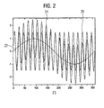
- the corresponding signature components and the resulting overall signature are shown by way of example in the diagram Fig. 2 shown.
- the angular position in the circumferential direction of the encoder 2 is removed on the x-axis as the location characteristic.
- a characteristic value characteristic of the respective magnetization is plotted on the ⁇ -axis.
- components of the magnetic signature in the exemplary embodiment on the one hand serves the first signature portion, corresponding to the curve 20, which has a sinusoidal course with a period length of 20 ° due to arranged with a period length of 20 ° pole pairs in the manner of a fundamental wave.
- This superimposed in the manner of a harmonic wave is the second signature component generated by said variation of the magnetization ratio, represented by the curve 22.
- the superimposition of these signature components produces the curve 24 as the overall signature.
- the magnetic field sensor arrangement 4 of the measuring system 1 comprises two magnetic field sensors 30 designed as Hall sensors in the exemplary embodiment, which are arranged at a distance from each other as viewed in the direction of rotation.
- the magnetic field sensors 30 are seen in the twisting direction at a distance corresponding to half the period length of the magnetic elements 8, that is arranged at a distance corresponding to a twist angle of 10 ° to each other.
- FIG Fig. 3 An alternative embodiment for a magnetic encoder 2 'is shown in FIG Fig. 3 shown.
- magnetic elements 8 are also arranged on the outer circumference of a carrier cylinder 6 periodically spaced from each other and with a period length kept constant. In the embodiment according to Fig. 3 however, they extend in their longitudinal direction parallel to the central axis of the carrier cylinder 6 and are spaced apart to form gaps or spaces.
- the magnetization ratios of the magnetic elements between the respective north pole component and south pole component vary according to a predetermined nominal sinusoidal curve in the exemplary embodiment, characterized by the black or white surface components of the magnetic elements 8 Fig. 4 In this case, the sinusoidal course of said nominal curve becomes clear.
Priority Applications (1)
| Application Number | Priority Date | Filing Date | Title |
|---|---|---|---|
| EP10004681A EP2385353A1 (fr) | 2010-05-04 | 2010-05-04 | Encodeur magnétique, notamment pour l'utilisation dans un système de mesure pour la mesure de la position absolue d'un corps pouvant être poussé ou tourné contre un corps de référence, et système de mesure |
Applications Claiming Priority (1)
| Application Number | Priority Date | Filing Date | Title |
|---|---|---|---|
| EP10004681A EP2385353A1 (fr) | 2010-05-04 | 2010-05-04 | Encodeur magnétique, notamment pour l'utilisation dans un système de mesure pour la mesure de la position absolue d'un corps pouvant être poussé ou tourné contre un corps de référence, et système de mesure |
Publications (1)
| Publication Number | Publication Date |
|---|---|
| EP2385353A1 true EP2385353A1 (fr) | 2011-11-09 |
Family
ID=43033070
Family Applications (1)
| Application Number | Title | Priority Date | Filing Date |
|---|---|---|---|
| EP10004681A Withdrawn EP2385353A1 (fr) | 2010-05-04 | 2010-05-04 | Encodeur magnétique, notamment pour l'utilisation dans un système de mesure pour la mesure de la position absolue d'un corps pouvant être poussé ou tourné contre un corps de référence, et système de mesure |
Country Status (1)
| Country | Link |
|---|---|
| EP (1) | EP2385353A1 (fr) |
Cited By (5)
| Publication number | Priority date | Publication date | Assignee | Title |
|---|---|---|---|---|
| EP2846126A1 (fr) * | 2013-09-04 | 2015-03-11 | Bogen Electronic GmbH | Dispositif de mesure et procédé de mesure de la position de corps |
| CN108216592A (zh) * | 2016-12-22 | 2018-06-29 | 利勃海尔航空航天林登贝格股份有限公司 | 用于对飞行器的装置进行操纵的促动器 |
| EP3367070A1 (fr) * | 2017-02-27 | 2018-08-29 | The Boeing Company | Appareil, système et procédé de détermination de la position d'une pièce |
| WO2019115231A1 (fr) * | 2017-12-11 | 2019-06-20 | Hartmann-exact KG | Dispositif de mesure d'angle de rotation |
| WO2021229169A1 (fr) | 2020-05-14 | 2021-11-18 | Electricfil Automotive | Procédé et dispositif de mesure de la position angulaire mécanique d'un rotor |
Citations (3)
| Publication number | Priority date | Publication date | Assignee | Title |
|---|---|---|---|---|
| DE102006006776A1 (de) * | 2005-02-11 | 2006-08-17 | Electricfil Automotive S.A.S. | Positionssensor mit kompensierten Magnetpolen |
| DE102006060622A1 (de) * | 2006-12-21 | 2008-06-26 | Robert Bosch Gmbh | Vorrichtung zur Stellungserfassung eines sich bewegenden Bauteils |
| EP2236990A2 (fr) * | 2009-03-31 | 2010-10-06 | BALLUFF GmbH | Système de mesure de position/trajectoire |
-
2010
- 2010-05-04 EP EP10004681A patent/EP2385353A1/fr not_active Withdrawn
Patent Citations (3)
| Publication number | Priority date | Publication date | Assignee | Title |
|---|---|---|---|---|
| DE102006006776A1 (de) * | 2005-02-11 | 2006-08-17 | Electricfil Automotive S.A.S. | Positionssensor mit kompensierten Magnetpolen |
| DE102006060622A1 (de) * | 2006-12-21 | 2008-06-26 | Robert Bosch Gmbh | Vorrichtung zur Stellungserfassung eines sich bewegenden Bauteils |
| EP2236990A2 (fr) * | 2009-03-31 | 2010-10-06 | BALLUFF GmbH | Système de mesure de position/trajectoire |
Cited By (10)
| Publication number | Priority date | Publication date | Assignee | Title |
|---|---|---|---|---|
| EP2846126A1 (fr) * | 2013-09-04 | 2015-03-11 | Bogen Electronic GmbH | Dispositif de mesure et procédé de mesure de la position de corps |
| WO2015032600A1 (fr) * | 2013-09-04 | 2015-03-12 | Bogen Electronic Gmbh | Dispositif de mesure et procédé permettant de mesurer la position d'un corps |
| CN108216592A (zh) * | 2016-12-22 | 2018-06-29 | 利勃海尔航空航天林登贝格股份有限公司 | 用于对飞行器的装置进行操纵的促动器 |
| EP3367070A1 (fr) * | 2017-02-27 | 2018-08-29 | The Boeing Company | Appareil, système et procédé de détermination de la position d'une pièce |
| CN108502137A (zh) * | 2017-02-27 | 2018-09-07 | 波音公司 | 用于确定部件位置的装置、系统和方法 |
| US10690520B2 (en) | 2017-02-27 | 2020-06-23 | The Boeing Company | Apparatus, system, and method for determining a position of a part |
| CN108502137B (zh) * | 2017-02-27 | 2022-09-23 | 波音公司 | 用于确定部件位置的装置、系统和方法 |
| WO2019115231A1 (fr) * | 2017-12-11 | 2019-06-20 | Hartmann-exact KG | Dispositif de mesure d'angle de rotation |
| WO2021229169A1 (fr) | 2020-05-14 | 2021-11-18 | Electricfil Automotive | Procédé et dispositif de mesure de la position angulaire mécanique d'un rotor |
| FR3110230A1 (fr) | 2020-05-14 | 2021-11-19 | Electricfil Automotive | Procédé et dispositif de mesure de la position angulaire mécanique d’un rotor |
Similar Documents
| Publication | Publication Date | Title |
|---|---|---|
| DE19818799C2 (de) | Verfahren und Vorrichtung zum Messen von Winkeln | |
| EP1797399B1 (fr) | Dispositif de mesure de la position absolue d'au moins deux corps deplaçables ou mobiles en rotation l'un par rapport a l'autre | |
| DE10334869B3 (de) | Drehwinkelsensor | |
| EP2072965B1 (fr) | Dispositif de mesure de position et procédé de détermination de la position absolue | |
| DE102005021300B4 (de) | Drehgeber | |
| EP2182330B1 (fr) | Système de mesure de position/trajectoire doté d'un corps de mesure codé | |
| DE102008059775A1 (de) | Absolut messende Lenkwinkelsensoranordnung | |
| DE10158223A1 (de) | Drehwinkel-Messgerät | |
| WO2002016879A1 (fr) | Procede de correction d'un angle de phase lors de l'exploration d'une piste de codage | |
| DE19817356A1 (de) | Winkelgeber und Verfahren zur Winkelbestimmung | |
| EP0575843A1 (fr) | Système de mesure angulaire | |
| DE102013224098A1 (de) | Sensoranordnung zur Erfassung von Drehwinkeln an einem rotierenden Bauteil in einem Fahrzeug | |
| DE10160450A1 (de) | Anordnung zum Detektieren der Bewegung eines Encoders | |
| EP0276402A1 (fr) | Codeur de position angulaire de grande précision avec détection fotoélectrique | |
| EP2385353A1 (fr) | Encodeur magnétique, notamment pour l'utilisation dans un système de mesure pour la mesure de la position absolue d'un corps pouvant être poussé ou tourné contre un corps de référence, et système de mesure | |
| DE102016002420A1 (de) | Verfahren zur Bestimmung der Position eines Magneten relativ zu einer Sensorzelle | |
| DE102011109551A1 (de) | Messsystem zur Positionsbestimmung eines gegenüber einem Referenzkörper verschiebbaren oder verdrehbaren Körpers mit einem magnetischen Encoder | |
| EP1260787A1 (fr) | Capteur d'angle utilisant des éléments de mesure magnétorésistifs | |
| DE10052609A1 (de) | Verfahren zur Kompensation einer Offsetdrift eines Winkelmessers | |
| DE102004001570B4 (de) | Messverfahren sowie Messvorrichtung zum Durchführen des Messverfahrens | |
| WO2006069925A1 (fr) | Element de mesure et procede de mesure comportant une piste pour la determination d'une position | |
| EP0341412A1 (fr) | Capteur de position angulaire codée | |
| DE10123539B4 (de) | Magnetische Längenmessvorrichtung | |
| DE102020128727B3 (de) | Drehgeber und Verfahren zur Bestimmung einer Winkelposition | |
| EP1243891B1 (fr) | Dispositif de mesure d'angle pour détecter avec précision la position absolue et le nombre de rotations d'un arbre |
Legal Events
| Date | Code | Title | Description |
|---|---|---|---|
| AK | Designated contracting states |
Kind code of ref document: A1 Designated state(s): AL AT BE BG CH CY CZ DE DK EE ES FI FR GB GR HR HU IE IS IT LI LT LU LV MC MK MT NL NO PL PT RO SE SI SK SM TR |
|
| AX | Request for extension of the european patent |
Extension state: BA ME RS |
|
| PUAI | Public reference made under article 153(3) epc to a published international application that has entered the european phase |
Free format text: ORIGINAL CODE: 0009012 |
|
| STAA | Information on the status of an ep patent application or granted ep patent |
Free format text: STATUS: THE APPLICATION IS DEEMED TO BE WITHDRAWN |
|
| 18D | Application deemed to be withdrawn |
Effective date: 20120510 |