EP2385101A1 - Klimaschrank mit mehreren Ein- und Ausgabestationen und Transportvorrichtungen - Google Patents
Klimaschrank mit mehreren Ein- und Ausgabestationen und Transportvorrichtungen Download PDFInfo
- Publication number
- EP2385101A1 EP2385101A1 EP11003535A EP11003535A EP2385101A1 EP 2385101 A1 EP2385101 A1 EP 2385101A1 EP 11003535 A EP11003535 A EP 11003535A EP 11003535 A EP11003535 A EP 11003535A EP 2385101 A1 EP2385101 A1 EP 2385101A1
- Authority
- EP
- European Patent Office
- Prior art keywords
- input
- climatic
- transport
- cabinet
- storage device
- Prior art date
- Legal status (The legal status is an assumption and is not a legal conclusion. Google has not performed a legal analysis and makes no representation as to the accuracy of the status listed.)
- Granted
Links
Images

Classifications
-
- C—CHEMISTRY; METALLURGY
- C12—BIOCHEMISTRY; BEER; SPIRITS; WINE; VINEGAR; MICROBIOLOGY; ENZYMOLOGY; MUTATION OR GENETIC ENGINEERING
- C12M—APPARATUS FOR ENZYMOLOGY OR MICROBIOLOGY; APPARATUS FOR CULTURING MICROORGANISMS FOR PRODUCING BIOMASS, FOR GROWING CELLS OR FOR OBTAINING FERMENTATION OR METABOLIC PRODUCTS, i.e. BIOREACTORS OR FERMENTERS
- C12M41/00—Means for regulation, monitoring, measurement or control, e.g. flow regulation
- C12M41/12—Means for regulation, monitoring, measurement or control, e.g. flow regulation of temperature
- C12M41/14—Incubators; Climatic chambers
-
- C—CHEMISTRY; METALLURGY
- C12—BIOCHEMISTRY; BEER; SPIRITS; WINE; VINEGAR; MICROBIOLOGY; ENZYMOLOGY; MUTATION OR GENETIC ENGINEERING
- C12M—APPARATUS FOR ENZYMOLOGY OR MICROBIOLOGY; APPARATUS FOR CULTURING MICROORGANISMS FOR PRODUCING BIOMASS, FOR GROWING CELLS OR FOR OBTAINING FERMENTATION OR METABOLIC PRODUCTS, i.e. BIOREACTORS OR FERMENTERS
- C12M23/00—Constructional details, e.g. recesses, hinges
- C12M23/48—Holding appliances; Racks; Supports
Definitions
- the invention relates to a climate cabinet with multiple input and output stations.
- the invention relates to a climate chamber.
- Climatic cabinets are usually used to store objects under defined climatic conditions such as a defined temperature or in an atmosphere of defined composition.
- climate cabinets are heat cabinets, refrigerators or incubators in which cell cultures or microorganisms are stored at elevated temperature and very high humidity and optionally in a carbon dioxide-enriched atmosphere for a long time.
- the objects are applied to suitable slides. Slides are, for example, the known microtiter plates.
- To accommodate the slides is located in the interior of the air conditioning cabinets usually at least one object storage device. These object storage devices are mounted in the interior either fixed or rotatable (so-called carousel).
- the interior of a climatic cabinet is usually accessible via a door that is large enough to post or remove an object storage device in the interior.
- the provision of a larger door also facilitates the cleaning and maintenance of the interior of a climate cabinet.
- the loading of an object storage device with slides is preferably carried out not by a larger door as mentioned above, but by a smaller opening or lock.
- a lock is adapted in their dimensions to the individually transported through them slides.
- the slides are usually brought out with the aid of a transport device through the opening or lock into the interior of the climatic chamber and again out of this.
- a transport device is integrated into the climatic chamber and takes over the loading and unloading of the slide through the lock and the transport between the lock and object storage device.
- one sluice per climate cabinet is provided in each case, the transport between the sluice and an object storage apparatus within the climate cabinet again taking place by means of a single transport device.
- this relates to a climate cabinet.
- This may, for example, be a heating cabinet, a refrigerator or an incubator.
- the climate chamber according to the invention has an object storage device, a first input and output station for inputting and outputting objects and an associated first transport device for positioning of objects in the object storage device and a second input and output station for inputting and outputting objects and an associated second transport device for positioning objects in the object storage device.
- the object storage device is used for storing objects. These objects can be solid or liquid objects. They may be, for example, chemical substances or biological objects. In particular, it may be cell cultures or microorganisms. These objects are stored in the object storage device.
- the objects can be stored on a slide, for example a microtiter plate, in the object storage device.
- the objects can also be introduced and stored without special slides in the climatic chamber.
- the object storage device itself can be designed differently. It may, for example, be a fixed or rotatably mounted object storage device. In the latter case, this is referred to as a so-called carousel. It may also be a stacker, which is generally in the form of a tower. In such a stacking device, various samples or objects can be stored or stacked in different compartments.
- the climate chamber has a first input and output station for inputting and outputting objects and an associated first transport device for positioning objects in the object storage device.
- the transport device ensures the transport of an input object through the input and output station to the object storage device also for the introduction of eg insertion of the object into the object storage device.
- the same transport device serves to transport the objects from the object storage device back to the input and output station, wherein in turn the transport device also carries out the actual process of removal of the object from the object storage device.
- the transport device may be formed in one or more parts.
- the input and output station can be configured differently.
- the input and output station can be permanently integrated into the climate chamber and located in particular within the climate chamber. But it is also possible that the input and output station is located outside of the air conditioning cabinet and / or only modularly attached to this or fixed.
- the associated transport device may be provided structurally within the climatic chamber. But it is also possible that the transport device is located outside of the climatic chamber and is integrated, for example, in a modular on the climatic cabinet provided input and output station.
- a second input and output station for inputting and outputting objects and an associated second transport device for positioning objects in the object storage device are also provided.
- the first input and output station is not identical to the second input and output station.
- the first transport device and the second transport device are not identical to one another. Otherwise, however, applies to the second input and output station as well as their associated second transport device with respect to the first input and output station and the associated first transport device said. In this case, both the first transport device and the second transport device can operate the object storage device.
- the transport devices have a movable tray on which the objects to be transported are transported.
- a transport of the objects can take place in each case in several directions: Frequently a transport in all three room dimensions is possible.
- This is often achieved by the use of a lift, which allows lifting or lowering of the objects to be transported.
- This lift system is often combined with a system for horizontal displacements, which are used in particular at the moment of access of the transport device to the object to be transported. For example, a transport device with tray moves with the help of the tablet under the object to be transported and can record this.
- a combination of a shift in the horizontal is realized with a rotation about a vertical axis, so that, for example, the positioning of an object in an object storage device relative to the climatic chamber in a different orientation than the input and output of the same object.
- the climatic cabinet is set up so that the two input and output stations and their associated transport devices can simultaneously input and / or output or transport objects. It is thus the case that the two transport devices can operate largely independently of one another. For example, an object can be simultaneously loaded onto the first transport device by the first input and output station, while at the same time another object is transferred by the second transport device to the second input and output station for output purposes. It is also conceivable that the first input and output station and its associated transport device is concerned with an input or output of an object, while at the same time the second transport device transports an object within the climatic cabinet or already positioned in the object storage device or from the object storage device extracts.
- Such a configuration of the climate chamber according to the invention makes it possible compared to the prior art, to realize a temporally optimized flow of process steps.
- the two input and output stations and their associated transport devices thus work largely independent of each other and each optimized in time.
- the climatic cabinet is configured so that only one of the transport devices can serve the object storage device at the same time.
- the first and second transport devices may again operate independently of each other.
- the described configuration is particularly useful if the object storage device is an object storage device rotatably arranged in the climatic chamber. In this case, the object storage device is first brought into a rotational position, which allows one of the two transport devices to access a selected compartment or a selected position in the object storage device. Subsequently, the object storage device can be rotated to another position, and the access is now possible for the other transport device. Similarly, an operation may occur when the object storage device is horizontally slidable in the climatic cabinet.
- the climatic chamber can be configured such that only one of the transport devices can operate the object storage device at the same time. This prevents possible collisions of the transport devices when accessing the object storage device with each other.
- the transport devices have a device for the vertical transport of objects. This can be realized, for example, via the lift system already mentioned above. This is particularly advantageous when the objects to be stored in the climatic chamber are stacked one above the other, for example, stored in a stacking device.
- the two transport devices are configured in the same way.
- both transport devices are configured in principle via the same transport options with regard to the transport directions and with regard to the objects to be transported with them.
- the transport devices need not necessarily be able to work with respect to the directions relative to the climatic chamber in exactly the same directions, instead, it is meant that the two transport devices have the same number and type of movement options.
- both transport devices each have a lift function, a rotation function and a horizontal shift function.
- the two transport devices are designed in different ways. This can affect both the directions of transport and the possibilities with regard to the objects to be transported.
- one of the two transport devices may have an additional shift function that the other transport device does not have. It is also possible, for example, for one transport device to be able to transport larger objects than the other transport device.
- the optional design of the transport device in the same way or in different ways allows a better individual adaptation of the climate chamber according to the invention to the respective user needs and allows a better and more individual system integration of the climate control cabinet in a laboratory environment.
- the two input and output stations of the climatic chamber are arranged on different sides of the climatic chamber.
- the two input and output stations can be arranged, for example, on adjacent sides of the climatic chamber or else on opposite sides of the climatic chamber.
- the first input and output station is arranged in a side wall of the climatic chamber, and that the second input and output station is located in a front surface of the climatic chamber.
- the first input and output station is located in a side wall of the climatic chamber, and that the second input and output station is located at the rear of the climatic chamber.
- first input and output station may be located on a first side surface, for example on the left, of the climatic chamber, and for the second input and output station to be located on the other side surface of the climatic chamber, for example on the right.
- the two input and output stations with respect to a bottom surface of the climatic chamber can be located at about the same height. But it is also possible that the two input and output stations are located at a different height relative to a bottom surface of the climate cabinet. Of course, it is also possible that the two input and output stations are not arranged on different sides of the climatic chamber, but on the same side of the climatic chamber.
- the input and output stations can be located centrally relative to a side surface of the climatic cabinet at this or laterally offset to this center.
- the climatic cabinet further comprises a door for removing the object storage device.
- This door is therefore considerably larger in size than the two input and output stations for inputting and outputting individual objects.
- an input and output station can also be located within the said door or integrated into it.
- a third input and output station is provided with an associated third transport device for positioning objects in the object storage device.
- the third transport device again differs from both the first and the second transport device.
- a fourth or further input and output station including transport device may be provided.
- this relates to a system with a climatic cabinet, as has been described above.
- the system according to the invention comprises a plurality of workstations, which are each arranged adjacent to the input and output stations of the climatic chamber, so that the transport devices of the climatic chamber associated with the input and output stations can also serve the workstations.
- the transport devices can thus transport objects to and from the workstations and also remove objects from the workstations.
- the workstations may differ in their functions, but they may also perform the same function. Examples of workstations are a dispenser or dispenser, a reader, a washer, a shaker, or a shaker. a sealing device (“sealer”) or a simple provision device for laboratory goods or objects to be handled in question.
- the climate cabinet of the system is arranged to control the workstations.
- the climate chamber according to the invention can be very easily combined with different workstations, and system integration is greatly facilitated.
- the climate chamber can thus be used to control the entire laboratory system, including the workstations.
- the climate cabinet has an internal control unit for controlling the climate cabinet itself and the workstations.
- the control unit is physically located inside the climate cabinet.
- the climate chamber has an external interface, via which the climate chamber and thus possibly the workstations are controlled.
- a connection to a conventional computer can be made, which accesses a software that allows a control of the climatic chamber.
- the software may be permanently installed on the computer, but it may also be portable, for example in the form of a CD or DVD or in the form of another data carrier.
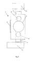
- Fig. 1 shows a climatic cabinet 1 in a schematic representation. It is a schematic plan view.
- the climate cabinet 1 shown is an incubator.
- an object storage device 2 which may be formed for example in the form of a carousel.
- the object storage device 2 has several compartments located in different planes, thus it is a stacking device. An access to the entire object storage device 2 can be done through the large door 7 of the climatic cabinet 1.
- an input or output of objects takes place through the two input and output stations 3 and 5.
- the two stations 3 and 5 are arranged on different sides of the climatic cabinet 1. In the example shown, they are located on adjacent sides. In the example shown, the input and output stations 3 and 5 are formed in the form of a small lock.
- the input and output station 3 is assigned a transport device 4.
- the inputs and Output station 5 is associated with a second transport device 6.
- the first transport device 4 provides for the input and output of objects through the input and output station 3 and for transport between the input and output station 3 on the one hand and the object storage device 2 on the other. Furthermore, the transport device 4 is able to enter objects transported on it directly into the object storage device 2 or to remove it from it.
- the transport device 6 allows input or output of objects through the input and output station 5 and a transport between the input and output station 5 on the one hand and the object storage device 2 on the other. Furthermore, with the aid of the transport device 6, a transported object can be directly fed into or taken out of the object storage device 2.
- the two transport devices 4 and 6 are configured substantially similar. They each have a shift function in the plane, via a rotation function, as well as in each case via a lift function, with the help of which objects to be transported along an axis, from the paper plane in Fig. 1 protrudes, can be transported. With the aid of this lift function object storage spaces in the object storage device 2, which are located at different heights, can be achieved by the transport devices 4 and 6, respectively.
- the climatic cabinet 1 is set up so that the two input and output stations 3 and 5 and their associated transport devices 4 and 6 can simultaneously input or output or transport objects.
- the two units of input and output station and associated transport device 3 and 4 or 5 and 6 thus operate largely independently.
- the climate cabinet shown is further configured such that only one of the transport devices 4 or 6 can operate the object storage device 2 at the same time.
- the rotatably mounted object storage device 2 is thus either brought into a position which allows access of the transport device 4 to a preselected compartment, or the object storage device 2 is brought into a position which permits access of the transport device 6 to another preselected compartment pre-selected storage space makes feasible. This allows a time-saving as well as safe process flow within the incubator 1.
- the in Fig. 1 shown incubator 1 can be easily integrated into a laboratory system with different workstations. These workstations can be arranged in the vicinity of the input and output stations 3 and 5 (in Fig. 1 not shown).
- Fig. 2 shows a schematic representation of a system with a climatic cabinet 1 and several workstations 8 and 9.
- the climatic cabinet 1 in turn has a larger door 7 through which through a cleaning and maintenance of the climatic cabinet 1 and access to the complete object storage device 2 is possible.
- the two input and output stations 3 and 5 which in turn are configured in the form of a lock, on opposite sides of the air conditioning cabinet 1.
- the respective input and output stations 3 and 5 is a transport device 4 and 6 assigned.
- These transport devices 4 and 6 allow input or output of objects through the input and output stations 3 and 5, a transport between the input and output stations 3 and 5 on the one hand and the object storage device 2 on the other hand and a loading or unloading of objects into or out of the object storage device 2.
- the two transport devices 4 and 6 are in turn designed in the same way, but they could also be configured in various ways. In the example shown, both are capable of performing both a horizontal displacement and a lifting movement along an axis Z pointing out of the plane of the paper as well as a rotational movement about this axis Z.
- the workstations can be workstations of different types.
- the workstation 9 is an object providing work station in which, for example, empty objects such as empty microtiter plates are provided, which are then fed into the climatic cabinet 1 through the input and output station 5 with the aid of the transport device 6.
- the work station 8 may be, for example, a filling device in which, for example, originally empty objects are filled with a certain substance, for example a specific solvent or an organic sample. For filling, for example, empty objects or object carriers can be removed from the object storage device 2 with the aid of the transport device 4.
- the filled objects can be returned with the aid of the transport device 4 through the input and output station 3 back into the climatic chamber 1 and back into the object storage device 2.
- the climate cabinet 1 and workstation 8 and 9 system are controlled by the climate cabinet 1.
- the climate chamber 1 via an internal control unit for controlling the air conditioning cabinet 1 and the work stations 8 and 9 have.
- the climate cabinet 1 shown has an external interface via which the entire climate chamber 1 can be controlled for the purpose of system control.
Landscapes
- Chemical & Material Sciences (AREA)
- Health & Medical Sciences (AREA)
- Wood Science & Technology (AREA)
- Organic Chemistry (AREA)
- Zoology (AREA)
- Life Sciences & Earth Sciences (AREA)
- Engineering & Computer Science (AREA)
- Bioinformatics & Cheminformatics (AREA)
- Microbiology (AREA)
- General Engineering & Computer Science (AREA)
- Genetics & Genomics (AREA)
- Sustainable Development (AREA)
- Biomedical Technology (AREA)
- General Health & Medical Sciences (AREA)
- Biochemistry (AREA)
- Biotechnology (AREA)
- Analytical Chemistry (AREA)
- Physics & Mathematics (AREA)
- Thermal Sciences (AREA)
- Clinical Laboratory Science (AREA)
- Warehouses Or Storage Devices (AREA)
- Apparatus Associated With Microorganisms And Enzymes (AREA)
Abstract
Description
- Die Erfindung bezieht sich auf einen Klimaschrank mit mehreren Ein- und Ausgabestationen.
- Die Erfindung betrifft einen Klimaschrank. Klimaschränke werden üblicherweise dazu verwendet, Objekte unter definierten klimatischen Bedingungen wie beispielsweise einer definierten Temperatur oder in einer Atmosphäre definierter Zusammensetzung aufzubewahren. Beispiele für Klimaschränke sind Wärmeschränke, Kühlschränke oder Inkubatoren, in denen Zellkulturen oder Mikroorganismen bei erhöhter Temperatur und sehr hoher Luftfeuchtigkeit und gegebenenfalls in einer mit Kohlendioxid angereicherten Atmosphäre über längere Zeit gelagert werden. Zu diesem Zweck sind die Objekte auf geeignete Objektträger aufgebracht. Objektträger sind beispielsweise die bekannten Mikrotiterplatten. Zur Aufnahme der Objektträger befindet sich im Innenraum der Klimaschränke üblicherweise mindestens eine Objektlagervorrichtung. Diese Objektlagervorrichtungen sind im Innenraum entweder feststehend oder drehbar gelagert (sogenanntes Karussell).
- Der Innenraum eines Klimaschrankes ist in der Regel über eine Türe zugänglich, die groß genug ist, um eine Objektlagervorrichtung im Innenraum zu postieren bzw. zu entnehmen. Das Vorsehen einer größeren Tür erleichtert auch die Reinigung und Wartung des Innenraums eines Klimaschrankes.
- Die Beschickung einer Objektlagervorrichtung mit Objektträgern erfolgt vorzugsweise nicht durch eine größere Tür wie oben erwähnt, sondern durch eine kleinere Öffnung bzw. Schleuse. Eine solche Schleuse ist in ihren Abmessungen an die durch sie einzeln hindurch zu transportierenden Objektträger angepasst. Durch die Verwendung einer kleineren Öffnung bzw. Schleuse ist es möglich, das Klima im Klimaschrank auf einem verhältnismäßig konstanten Niveau zu halten, verglichen mit der Beschickung durch eine große Haupttür.
- Die Objektträger werden üblicherweise mit Hilfe einer Transportvorrichtung durch die Öffnung bzw. Schleuse in den Innenraum des Klimaschrankes hinein und auch wieder aus diesem herausgebracht. Häufig ist eine solche Transportvorrichtung in den Klimaschrank integriert und übernimmt das Be- bzw. Entladen der Objektträger durch die Schleuse sowie den Transport zwischen Schleuse und Objektlagervorrichtung. Im Allgemeinen ist gemäß des Standes der Technik jeweils eine Schleuse pro Klimaschrank vorgesehen, wobei der Transport zwischen der Schleuse und einer Objektlagervorrichtung innerhalb des Klimaschrankes wiederum mittels einer einzigen Transportvorrichtung erfolgt.
- Aus der
DE 20 2008 013 492 U1 ist ein anderer Klimaschrank mit mindestens zwei Ein- und Ausgabestationen bekannt. Dabei sind jeweils zwei Ein- und Ausgabestationen zu einem Paar von Stationen zusammengefasst. Dieses Paar von Ein- und Ausgabestationen ist so angeordnet bzw. konstruiert, dass eine einzelne Transportvorrichtung, die sich bevorzugt im Inneren des Klimaschrankes befindet, beide Ein- und Ausgabestationen des Paares bedienen kann. Darüber hinaus bedient dieselbe Transportvorrichtung auch die im Inneren des Klimaschrankes angeordnete Objektlagervorrichtung. Das paarige Vorsehen von Ein- und Ausgabestationen erleichtert bereits die Integration eines Klimaschrankes in ein System mit mehreren Arbeitsstationen. Dennoch erscheint es wünschenswert, eine noch einfachere Integration eines Klimaschrankes in ein System mit mehreren Arbeitsstationen zu realisieren, wobei insbesondere auch eine größere Flexibilität hinsichtlich der Systemintegration möglich sein soll. - Es ist die Aufgabe der vorliegenden Erfindung, einen Klimaschrank bereitzustellen, der sich noch besser und flexibler in ein System mit mehreren Arbeitsstationen integrieren lässt. Des Weiteren soll der erfindungsgemäße Klimaschrank auch eine schnellere Handhabung von Objekten erlauben.
- Die Aufgabe wird gelöst durch die unabhängigen Patentansprüche. Die abhängigen Ansprüche sind auf vorteilhafte Ausführungsformen der Erfindung gerichtet.
- Gemäß einem ersten Aspekt der Erfindung bezieht sich diese auf einen Klimaschrank. Dabei kann es sich beispielsweise um einen Wärmeschrank, einen Kühlschrank oder einen Inkubator handeln. Der erfindungsgemäße Klimaschrank weist eine Objektlagervorrichtung, eine erste Ein- und Ausgabestation zum Ein- und Ausgeben von Objekten und eine zugehörige erste Transportvorrichtung zum Positionieren von Objekten in der Objektlagervorrichtung sowie eine zweite Ein- und Ausgabestation zum Ein- und Ausgeben von Objekten und eine zugehörige zweite Transportvorrichtung zum Positionieren von Objekten in der Objektlagervorrichtung auf. Die Objektlagervorrichtung dient zum Lagern von Objekten. Bei diesen Objekten kann es sich um Objekte im festen oder flüssigen Aggregatzustand handeln. Es kann sich beispielsweise um chemische Substanzen oder biologische Objekten handeln. Insbesondere kann es sich um Zellkulturen oder Mikroorganismen handeln. Diese Objekte werden in der Objektlagervorrichtung gelagert. Dabei ist es insbesondere möglich, dass die Objekte auf einem Objektträger, wie zum Beispiel einer Mikrotiterplatte, in der Objektlagervorrichtung gelagert werden. Die Objekte können jedoch auch ohne speziellen Objektträger in den Klimaschrank eingebracht und gelagert werden. Die Objektlagervorrichtung selbst kann unterschiedlich ausgestaltet sein. Es kann sich beispielsweise um eine feststehende oder drehbar gelagerte Objektlagervorrichtung handeln. In letzterem Fall wird diese als so genanntes Karussell bezeichnet. Es kann sich auch um eine Stapelvorrichtung (engl. "stacker") handeln, welche im Allgemeinen in Form eines Turmes ausgebildet ist. In einer solchen Stapelvorrichtung können verschiedene Proben bzw. Objekte in verschiedenen Fächern aufbewahrt bzw. aufgestapelt werden.
- Erfindungsgemäß verfügt der Klimaschrank über eine erste Ein- und Ausgabestation zum Ein- und Ausgeben von Objekten und eine zugehörige erste Transportvorrichtung zum Positionieren von Objekten in der Objektlagervorrichtung. Es erfolgt somit eine Zuordnung zwischen der ersten Ein- und Ausgabestation einerseits und einer Transportvorrichtung andererseits. Die Transportvorrichtung sorgt dabei für den Transport eines eingegebenen Objektes durch die Ein- und Ausgabestation zur Objektlagervorrichtung auch für das Einbringen z.B. Hineinschieben des Objektes in die Objektlagervorrichtung. Des Weiteren dient dieselbe Transportvorrichtung dazu, die Objekte von der Objektlagervorrichtung zurück zu der Ein- und Ausgabestation zu transportieren, wobei wiederum die Transportvorrichtung auch den eigentlichen Prozess der Entnahme des Objektes aus der Objektlagervorrichtung vornimmt. Dabei kann die Transportvorrichtung ein- oder mehrteilig ausgebildet sein. Die Ein- und Ausgabestation kann unterschiedlich ausgestaltet sein. Es kann sich um eine einfache Öffnung oder aber um eine komplette Ein- und Ausgabestation mit Zubehör und/oder Schleusenfunktion handeln. Die Ein- und Ausgabestation kann dauerhaft in den Klimaschrank integriert sein und sich insbesondere innerhalb des Klimaschrankes befinden. Es ist aber auch möglich, dass sich die Ein- und Ausgabestation außerhalb des Klimaschrankes befindet und/oder lediglich modular an diesem befestigbar bzw. befestigt ist. Die zugehörige Transportvorrichtung kann konstruktiv innerhalb des Klimaschrankes vorgesehen sein. Es ist aber auch möglich, dass die Transportvorrichtung sich außerhalb des Klimaschrankes befindet und beispielsweise in eine modular am Klimaschrank vorgesehene Ein- und Ausgabestation integriert ist.
- Erfindungsgemäß ist auch eine zweite Ein- und Ausgabestation zum Ein- und Ausgeben von Objekten und eine zugehörige zweite Transportvorrichtung zum Positionieren von Objekten in der Objektlagervorrichtung vorgesehen. Die erste Ein- und Ausgabestation ist nicht identisch mit der zweiten Ein- und Ausgabestation. Des Weiteren sind die erste Transportvorrichtung und die zweite Transportvorrichtung nicht identisch miteinander. Ansonsten jedoch gilt für die zweite Ein- und Ausgabestation sowie für ihre zugehörige zweite Transportvorrichtung das bezüglich der ersten Ein- und Ausgabestation und der zugehörigen ersten Transportvorrichtung Ausgesagte. Dabei kann sowohl die erste Transportvorrichtung als auch die zweite Transportvorrichtung die Objektlagervorrichtung bedienen.
- Die prinzipielle konstruktive Ausgestaltung solcher Transportvorrichtungen ist im Prinzip aus dem Stand der Technik bekannt. Häufig verfügen die Transportvorrichtungen über ein bewegliches Tablett, auf dem die zu transportierenden Objekte transportiert werden. Ein Transport der Objekte kann dabei jeweils in mehrere Richtungen erfolgen: Häufig ist ein Transport in allen drei Raumdimensionen möglich. Realisiert wird dies häufig durch die Verwendung eines Liftes, der ein Anheben bzw. Absenken der zu transportierenden Objekte ermöglicht. Kombiniert wird dieses Liftsystem häufig mit einem System für horizontale Verschiebungen, welche insbesondere im Moment des Zugriffes der Transportvorrichtung auf das zu transportierende Objekt verwendet werden. Beispielsweise fährt eine Transportvorrichtung mit Tablett mit Hilfe des Tablettes unter das zu transportierende Objekt und kann dieses aufnehmen. Häufig ist für Transportzwecke auch eine Kombination einer Verschiebung in der Horizontalen mit einer Drehung um eine vertikale Achse realisiert, so dass beispielsweise das Positionieren eines Objektes in einer Objektlagervorrichtung bezogen auf den Klimaschrank in einer anderen Orientierung erfolgen kann als das Ein- und Ausgeben desselben Objektes.
- Gemäß einer bevorzugten Ausführungsform der Erfindung ist der Klimaschrank so eingerichtet, dass die beiden Ein- und Ausgabestationen und ihre zugehörigen Transportvorrichtungen gleichzeitig Objekte ein- und/oder ausgeben bzw. transportieren können. Es ist also so, dass die beiden Transportvorrichtungen weitgehend unabhängig voneinander in Betrieb sein können. Beispielsweise kann gleichzeitig durch die erste Ein- und Ausgabestation ein Objekt auf die erste Transportvorrichtung eingeladen werden, während gleichzeitig ein anderes Objekt durch die zweite Transportvorrichtung an die zweite Ein- und Ausgabestation für Ausgabezwecke übergeben wird. Es ist auch denkbar, dass die erste Ein- und Ausgabestation und ihre zugehörige Transportvorrichtung mit einer Ein- oder Ausgabe eines Objektes befasst ist, während zeitgleich die zweite Transportvorrichtung ein Objekt innerhalb des Klimaschrankes transportiert oder aber bereits in der Objektlagervorrichtung positioniert oder aber aus der Objektlagervorrichtung entnimmt. Eine solche Konfiguration des erfindungsgemäßen Klimaschrankes ermöglicht es verglichen mit dem Stand der Technik, einen zeitlich optimierteren Ablauf von Prozessschritten zu realisieren. Die beiden Ein- und Ausgabestationen und ihre zugehörigen Transportvorrichtungen arbeiten mithin weitgehend unabhängig voneinander und jeweils für sich zeitlich optimiert.
- Gemäß einer weiteren bevorzugten Ausführungsform der Erfindung ist der Klimaschrank so konfiguriert, dass lediglich eine der Transportvorrichtungen die Objektlagervorrichtung zur selben Zeit bedienen kann. Abgesehen von dieser Einschränkung können die erste und die zweite Transportvorrichtung jedoch wiederum unabhängig voneinander arbeiten. Die beschriebene Konfiguration ist insbesondere dann sinnvoll, wenn es sich bei der Objektlagervorrichtung um eine drehbar im Klimaschrank angeordnete Objektlagervorrichtung handelt. In diesem Fall wird die Objektlagervorrichtung zunächst in eine Drehposition gebracht, die einer der beiden Transportvorrichtungen den Zugriff auf ein ausgewähltes Fach bzw. eine ausgewählte Position in der Objektlagervorrichtung erlaubt. Anschließend kann die Objektlagervorrichtung in eine andere Position gedreht werden, und der Zugriff ist für die andere Transportvorrichtung nun möglich. In ähnlicher Weise kann ein Vorgang ablaufen, wenn die Objektlagervorrichtung in dem Klimaschrank horizontal verschiebbar angeordnet ist. Auch im Falle einer bezüglich des Klimaschrankes fest vorgesehenen Objektlagervorrichtung kann der Klimaschrank so konfiguriert sein, dass lediglich eine der Transportvorrichtungen die Objektlagervorrichtung zur selben Zeit bedienen kann. Dies verhindert mögliche Kollisionen der Transportvorrichtungen beim Zugriff auf die Objektlagervorrichtung miteinander.
- Gemäß einer bevorzugten Ausführungsform der Erfindung verfügen die Transportvorrichtungen über eine Einrichtung zum vertikalen Transport von Objekten. Dies kann beispielsweise über das bereits oben angesprochene Liftsystem realisiert werden. Dies ist insbesondere dann von Vorteil, wenn die im Klimaschrank zu lagernden Objekte übereinander aufgestapelt sind, beispielsweise in einer Stapelvorrichtung gelagert werden.
- Gemäß einer weiteren bevorzugten Ausführungsform der Erfindung sind die beiden Transportvorrichtungen in der gleichen Weise ausgestaltet. Dies bedeutet, dass beide Transportvorrichtungen im Prinzip über die gleichen Transportmöglichkeiten hinsichtlich der Transportrichtungen und hinsichtlich der mit ihnen zu transportierenden Objekte ausgestaltet sind. Dabei müssen die Transportvorrichtungen hinsichtlich der Richtungen nicht zwangsläufig bezogen auf den Klimaschrank in exakt denselben Richtungen arbeiten können, stattdessen ist gemeint, dass die beiden Transportvorrichtungen über dieselbe Anzahl und Art von Bewegungsmöglichkeiten verfügen. Beispielsweise können beide Transportvorrichtungen jeweils über eine Liftfunktion, eine Drehfunktion und über eine Verschiebefunktion in der Horizontalen verfügen.
- Gemäß einer alternativen Ausführungsform der Erfindung sind die beiden Transportvorrichtungen in unterschiedlicher Weise ausgestaltet. Dies kann sowohl die Richtungen des Transportes als auch die Möglichkeiten hinsichtlich der zu transportierenden Objekte betreffen. Beispielsweise kann eine der beiden Transportvorrichtungen über eine zusätzliche Verschiebefunktion verfügen, über die die andere Transportvorrichtung nicht verfügt. Es ist beispielsweise auch möglich, dass die eine Transportvorrichtung größere Objekte als die andere Transportvorrichtung transportieren kann. Die wahlweise Ausgestaltung der Transportvorrichtung in der gleichen Weise oder aber in unterschiedlicher Weise erlaubt eine bessere individuelle Anpassung des erfindungsgemäßen Klimaschrankes an die jeweiligen Nutzerbedürfnisse und gestattet eine bessere und individuellere Systemintegration des Klimaschrankes in eine Laborumgebung.
- Gemäß einer bevorzugten Ausführungsform der Erfindung sind die beiden Ein- und Ausgabestationen des Klimaschrankes an verschiedenen Seiten des Klimaschrankes angeordnet. Dabei können die beiden Ein- und Ausgabestationen z.B. an benachbarten Seiten des Klimaschrankes oder aber auch an einander gegenüberliegenden Seiten des Klimaschrankes angeordnet sein. Es ist beispielsweise möglich, dass die erste Ein- und Ausgabestation in einer Seitenwand des Klimaschrankes angeordnet ist, und dass sich die zweite Ein- und Ausgabestation in einer Frontfläche des Klimaschrankes befindet. Alternativ ist es auch möglich, dass sich die erste Ein- und Ausgabestation in einer Seitenwand des Klimaschrankes befindet, und dass sich die zweite Ein- und Ausgabestation an der Rückseite des Klimaschrankes befindet. Es ist auch möglich, dass sich die erste Ein- und Ausgabestation an einer ersten Seitenfläche, beispielsweise links, des Klimaschrankes befindet, und dass sich die zweite Ein- und Ausgabestation an der anderen Seitenfläche des Klimaschrankes, beispielsweise rechts, befindet. In allen Fällen können sich die beiden Ein- und Ausgabestationen bezüglich einer Bodenfläche des Klimaschrankes in etwa in derselben Höhe befinden. Es ist aber auch möglich, dass sich die beiden Ein- und Ausgabestationen bezogen auf eine Bodenfläche des Klimaschrankes in unterschiedlicher Höhe befinden. Selbstverständlich ist es auch möglich, dass die beiden Ein- und Ausgabestationen nicht an verschiedenen Seiten des Klimaschrankes, sondern an derselben Seite des Klimaschrankes angeordnet sind. Die Ein- und Ausgabestationen können sich bezogen auf eine Seitenfläche des Klimaschrankes zentral mittig an dieser oder aber seitlich versetzt zu dieser Mitte befinden.
- Gemäß einer weiteren Ausführungsform der Erfindung weist der Klimaschrank des Weiteren eine Tür zum Entfernen der Objektlagervorrichtung auf. Diese Tür ist mithin in ihren Abmessungen deutlich größer als die beiden Ein- und Ausgabestationen zum Ein- und Ausgeben von einzelnen Objekten. Gemäß einer Ausführungsform der Erfindung kann sich eine Ein- und Ausgabestation auch innerhalb der genannten Tür befinden bzw. in diese integriert sein.
- Selbstverständlich ist es auch möglich, dass zusätzlich zu der ersten und zweiten Ein- und Ausgabestation mit der jeweils zugehörigen ersten bzw. zweiten Transportvorrichtung eine dritte Ein- und Ausgabestation mit einer zugehörigen dritten Transportvorrichtung zum Positionieren von Objekten in der Objektlagervorrichtung vorgesehen ist. Dabei unterscheidet sich die dritte Transportvorrichtung wiederum sowohl von der ersten als auch von der zweiten Transportvorrichtung. In ähnlicher Weise kann auch eine vierte oder weitere Ein- und Ausgabestation samt Transportvorrichtung vorgesehen sein.
- Gemäß einem weiteren Aspekt der Erfindung bezieht sich diese auf ein System mit einem Klimaschrank, wie er vorstehend beschrieben worden ist. Des Weiteren umfasst das erfindungsgemäße System mehrere Arbeitsstationen, die jeweils benachbart zu den Ein- und Ausgabestationen des Klimaschrankes angeordnet sind, so dass die zu den Ein- und Ausgabestationen zugehörigen Transportvorrichtungen des Klimaschrankes auch die Arbeitsstationen bedienen können. Beispielsweise können die Transportvorrichtungen also Objekte zu den Arbeitsstationen transportieren und in diese hinein geben sowie auch Objekte aus den Arbeitsstationen heraus entnehmen. Dabei können sich die Arbeitsstationen hinsichtlich ihrer Funktionen voneinander unterscheiden, sie können aber auch dieselbe Funktion ausüben. Als Arbeitsstationen kommen beispielsweise eine Spendervorrichtung bzw. Befüllvorrichtung (engl. "dispenser"), eine Detektionsvorrichtung (engl. "reader"), eine Waschvorrichtung (engl. "washer"), eine Schüttelvorrichtung bzw. Rührvorrichtung (engl. "shaker"), eine Versiegelungsvorrichtung (engl. "sealer") oder aber eine simple Bereitstellungsvorrichtung für Laborware bzw. zu handhabende Objekte in Frage.
- Gemäß einer bevorzugten Ausführungsform der Erfindung ist der Klimaschrank des Systems eingerichtet, um die Arbeitsstationen zu steuern. Auf diese Art und Weise kann der erfindungsgemäße Klimaschrank sehr einfach mit verschiedenen Arbeitsstationen kombiniert werden, und eine Systemintegration ist deutlich erleichtert. Über den Klimaschrank kann somit eine Steuerung des gesamten Laborsystems inklusive der Arbeitsstationen erreicht werden.
- Gemäß einer bevorzugten Ausführungsform verfügt der Klimaschrank über eine interne Steuereinheit zum Steuern des Klimaschrankes selbst und der Arbeitsstationen. Das bedeutet, dass sich die Steuereinheit physikalisch innerhalb des Klimaschrankes befindet. Alternativ ist es aber auch möglich, dass der Klimaschrank über eine externe Schnittstelle verfügt, über die der Klimaschrank und damit gegebenenfalls auch die Arbeitsstationen ansteuerbar sind. Beispielsweise kann über eine solche externe Schnittstelle eine Verbindung zu einem herkömmlichen Computer hergestellt werden, der auf eine Software zugreift, die ein Ansteuern des Klimaschrankes erlaubt. Die Software kann fest auf dem Computer installiert sein, sie kann aber auch tragbar, beispielsweise in Form einer CD oder DVD oder in Form eines anderen Datenträgers bereitgestellt sein.
- Die vorstehend beschriebenen Ausführungsbeispiele des Klimaschrankes bzw. des Systems aus Klimaschrank und mehreren Arbeitsstationen können ganz oder teilweise miteinander kombiniert werden.
- Die vorstehend beschriebene Erfindung wird noch besser verstanden werden unter Bezugnahme auf die beigefügten Zeichnungen:
- Fig. 1:
- zeigt schematisch einen erfindungsgemäßen Klimaschrank mit zwei Ein- und Ausgabestationen sowie den jeweils zugehörigen Transportvorrichtungen; und
- Fig. 2:
- zeigt schematisch eine alternative Ausführungsform eines erfindungsgemäßen Klimaschrankes, der in ein System mit zwei Arbeitsstationen integriert ist.
-
Fig. 1 zeigt einen Klimaschrank 1 in schematischer Darstellung. Es handelt sich dabei um eine schematische Draufsicht. Bei dem gezeigten Klimaschrank 1 handelt es sich um einen Inkubator. Innerhalb des Inkubators befindet sich eine Objektlagervorrichtung 2, die beispielsweise in Form eines Karussells ausgebildet sein kann. Die Objektlagervorrichtung 2 verfügt über mehrere in unterschiedlichen Ebenen befindliche Fächer, es handelt sich somit um eine Stapelvorrichtung. Ein Zugriff auf die gesamte Objektlagervorrichtung 2 kann durch die große Tür 7 des Klimaschrankes 1 erfolgen. - Im Betrieb des Inkubators 1 erfolgt eine Ein- bzw. Ausgabe von Objekten durch die beiden Ein- und Ausgabestationen 3 und 5. Die beiden Stationen 3 und 5 sind an verschiedenen Seiten des Klimaschrankes 1 angeordnet. Im gezeigten Beispiel befinden sie sich an einander benachbarten Seiten. Im gezeigten Beispiel sind die Ein- und Ausgabestationen 3 sowie 5 in Form einer kleinen Schleuse ausgebildet. Der Ein- und Ausgabestation 3 ist dabei eine Transportvorrichtung 4 zugeordnet. Der Ein- und Ausgabestation 5 ist eine zweite Transportvorrichtung 6 zugeordnet. Die erste Transportvorrichtung 4 sorgt für das Ein- und Ausgeben von Objekten durch die Ein- und Ausgabestation 3 sowie für einen Transport zwischen der Ein- und Ausgabestation 3 einerseits und der Objektlagervorrichtung 2 andererseits. Des Weiteren ist die Transportvorrichtung 4 in der Lage, auf ihr transportierte Objekte direkt in die Objektlagervorrichtung 2 einzugeben bzw. aus dieser zu entnehmen. In analoger Art und Weise ermöglicht die Transportvorrichtung 6 ein Ein- bzw. Ausgeben von Objekten durch die Ein- und Ausgabestation 5 sowie einen Transport zwischen der Ein- und Ausgabestation 5 einerseits und der Objektlagervorrichtung 2 andererseits. Des Weiteren kann mit Hilfe der Transportvorrichtung 6 ein transportiertes Objekt direkt in die Objektlagervorrichtung 2 hineingegeben bzw. aus dieser entnommen werden. Im gezeigten Ausführungsbeispiel sind die beiden Transportvorrichtungen 4 und 6 im Wesentlichen gleichartig ausgestaltet. Sie verfügen jeweils über eine Verschiebefunktion in der Ebene, über eine Drehfunktion, sowie jeweils über eine Liftfunktion, mit deren Hilfe zu transportierende Objekte entlang einer Achse, die aus der Papierebene in
Fig. 1 hinausragt, transportiert werden können. Mit Hilfe dieser Liftfunktion können Objektlagerplätze in der Objektlagervorrichtung 2, die sich in unterschiedlicher Höhe befinden, durch die Transportvorrichtungen 4 bzw. 6 erreicht werden. - Im gezeigten Ausführungsbeispiel ist der Klimaschrank 1 so eingerichtet, dass die beiden Ein- und Ausgabestation 3 bzw. 5 und ihre zugehörigen Transportvorrichtungen 4 bzw. 6 gleichzeitig Objekte ein- oder ausgeben bzw. transportieren können. Die beiden Einheiten aus Ein- und Ausgabestation und zugehöriger Transportvorrichtung 3 und 4 bzw. 5 und 6 arbeiten somit weitgehend unabhängig voneinander. Allerdings ist der gezeigte Klimaschrank des Weiteren so konfiguriert, dass lediglich eine der Transportvorrichtungen 4 oder 6 die Objektlagervorrichtung 2 zur selben Zeit bedienen kann. Die drehbar gelagerte Objektlagervorrichtung 2 wird also entweder in eine Position gebracht, die einen Zugriff der Transportvorrichtung 4 auf ein vorausgewähltes Fach ermöglicht, oder aber die Objektlagervorrichtung 2 wird in eine Position gebracht, die einen Zugriff der Transportvorrichtung 6 auf ein anderes vorausgewähltes Fach bzw. einen vorausgewählten Lagerplatz realisierbar macht. Dies ermöglicht einen sowohl Zeit sparenden als auch sicheren Prozessablauf innerhalb des Inkubators 1.
- Der in
Fig. 1 gezeigte Inkubator 1 kann problemlos in ein Laborsystem mit verschiedenen Arbeitsstationen integriert werden. Diese Arbeitsstationen können in der Nähe der Ein- und Ausgabestationen 3 bzw. 5 angeordnet werden (inFig. 1 nicht dargestellt). -
Fig. 2 zeigt in schematischer Darstellung ein System mit einem Klimaschrank 1 und mehreren Arbeitsstationen 8 und 9. Der Klimaschrank 1 verfügt wiederum über eine größere Türe 7, durch die hindurch eine Reinigung und Wartung des Klimaschrankes 1 sowie ein Zugriff auf die komplette Objektlagervorrichtung 2 möglich ist. - Im dargestellten Ausführungsbeispiel befinden sich die beiden Ein- und Ausgabestationen 3 bzw. 5, die wiederum in Form einer Schleuse ausgestaltet sind, an einander gegenüberliegenden Seiten des Klimaschrankes 1. Den jeweiligen Ein- und Ausgabestationen 3 bzw. 5 ist jeweils eine Transportvorrichtung 4 bzw. 6 zugeordnet. Diese Transportvorrichtungen 4 und 6 erlauben ein Ein- oder Ausgeben von Objekten durch die Ein- und Ausgabestationen 3 bzw. 5, einen Transport zwischen den Ein- und Ausgabestationen 3 bzw. 5 einerseits und der Objektlagervorrichtung 2 andererseits sowie ein Bestücken bzw. Entnehmen von Objekten in die Objektlagervorrichtung 2 hinein bzw. aus dieser heraus. Die beiden Transportvorrichtungen 4 und 6 sind wiederum in gleicher Art und Weise ausgestaltet, sie könnten aber auch in verschiedener Art und Weise ausgestaltet sein. Im gezeigten Beispiel sind beide dazu in der Lage, sowohl eine horizontale Verschiebung als auch eine Hubbewegung entlang einer aus der Papierebenen herauszeigenden Achse Z sowie eine Drehbewegung um diese Achse Z durchzuführen.
- An die beiden Ein- und Ausgabestationen 3 und 5 angeschlossen sind die beiden Arbeitsstationen 8 und 9. Bei den Arbeitsstationen kann es sich um Arbeitsstationen unterschiedlicher Art handeln. Beispielsweise ist es möglich, dass es sich bei der Arbeitsstation 9 um eine Objektbereitstellungsarbeitsstation handelt, in der beispielsweise leere Objekte wie beispielsweise leere Mikrotiterplatten bereitgestellt werden, die dann durch die Ein- und Ausgabestation 5 mit Hilfe der Transportvorrichtung 6 in den Klimaschrank 1 hineingegeben werden. Bei der Arbeitsstation 8 kann es sich beispielsweise um eine Befüllvorrichtung handeln, in der beispielsweise ursprünglich leere Objekte mit einem bestimmten Stoff wie beispielsweise einem bestimmten Lösungsmittel oder einer organischen Probe befüllt werden. Zum Befüllen können beispielsweise leere Objekte bzw. Objektträger aus der Objektlagervorrichtung 2 mit Hilfe der Transportvorrichtung 4 entnommen werden. Sie werden mit Hilfe der Transportvorrichtung 4 zu der Ein- und Ausgabestation 3 transportiert und durch diese ausgegeben sowie der Befüllvorrichtung 8 bereitgestellt. Nach dem in der Befüllvorrichtung 8 erfolgten Befüllvorgang kann eine Rückführung der befüllten Objekte mit Hilfe der Transportvorrichtung 4 durch die Ein- und Ausgabestation 3 hindurch zurück in den Klimaschrank 1 und in diesem zurück in die Objektlagervorrichtung 2 erfolgen.
- In dem gezeigten Beispiel ist es so, dass das System aus Klimaschrank 1 und Arbeitsstationen 8 und 9 durch den Klimaschrank 1 gesteuert wird. Dazu kann der Klimaschrank 1 über eine interne Steuereinheit zum Steuern des Klimaschrankes 1 und der Arbeitsstationen 8 und 9 verfügen. Es ist aber auch möglich, dass der gezeigte Klimaschrank 1 über eine externe Schnittstelle verfügt, über die der gesamte Klimaschrank 1 zum Zwecke der Systemsteuerung ansteuerbar ist.
- Mit Hilfe der Erfindung ist es also möglich, einen Klimaschrank auf einfache Art und Weise in eine bestehende Laborumgebung mit verschiedenen Arbeitsstationen zu integrieren. Die dort durchgeführten Prozessschritte können zeitlich optimiert und individuell ausgeführt werden.
Claims (18)
- Klimaschrank (1), der Folgendes aufweist:eine Objektlagervorrichtung (2);eine erste Ein- und Ausgabestation (3) zum Ein- und Ausgeben von Objekten und eine zugehörige erste Transportvorrichtung (4) zum Positionieren von Objekten in der Objektlagervorrichtung (2); undeine zweite Ein- und Ausgabestation (5) zum Ein- und Ausgeben von Objekten und eine zugehörige zweite Transportvorrichtung (6) zum Positionieren von Objekten in der Objektlagervorrichtung (2).
- Klimaschrank (1) gemäß Anspruch 1, wobei die beiden Ein- und Ausgabestationen (3, 5) an verschiedenen Seiten des Klimaschrankes (1) angeordnet sind.
- Klimaschrank (1) gemäß einem der vorangehenden Ansprüche, wobei die beiden Ein- und Ausgabestationen (3, 5) an benachbarten Seiten des Klimaschrankes (1) angeordnet sind.
- Klimaschrank (1) gemäß einem der Ansprüche 1 bis 2, wobei die beiden Ein- und Ausgabestationen (3, 5) an einander gegenüberliegenden Seiten des Klimaschrankes (1) angeordnet sind.
- Klimaschrank (1) gemäß einem der vorangehenden Ansprüche, wobei die Objektlagervorrichtung (2) drehbar in dem Klimaschrank (1) angeordnet ist.
- Klimaschrank (1) gemäß einem der vorangehenden Ansprüche, wobei die Objektlagervorrichtung (2) eine Stapelvorrichtung (engl. "stacker") umfasst.
- Klimaschrank (1) gemäß einem der vorangehenden Ansprüche, der so eingerichtet ist, dass die beiden Ein- und Ausgabestationen (3, 5) und ihre zugehörigen Transportvorrichtungen (4, 6) gleichzeitig Objekte ein- oder ausgeben bzw. transportieren können.
- Klimaschrank (1) gemäß einem der vorangehenden Ansprüche, der so konfiguriert ist, dass lediglich eine der Transportvorrichtungen (4, 6) die Objektlagervorrichtung (2) zur selben Zeit bedienen kann.
- Klimaschrank (1) gemäß einem der vorangehenden Ansprüche, wobei die Transportvorrichtungen (4, 6) über eine Einrichtung zum vertikalen Transport von Objekten verfügen.
- Klimaschrank (1) gemäß einem der vorangehenden Ansprüche, wobei die beiden Transportvorrichtungen (4, 6) in der gleichen Weise ausgestaltet sind.
- Klimaschrank (1) gemäß einem der Ansprüche 1 bis 9, wobei die beiden Transportvorrichtungen (4, 6) in unterschiedlicher Weise ausgestaltet sind.
- Klimaschrank (1) gemäß einem der vorangehenden Ansprüche mit einer Steuereinheit zum Steuern des Klimaschrankes (1).
- Klimaschrank (1) gemäß einem der vorangehenden Ansprüche, der des Weiteren eine Tür (7) zum Entfernen der Objektlagervorrichtung (2) aufweist.
- Klimaschrank (1) gemäß einem der vorangehenden Ansprüche, wobei der Klimaschrank (1) ein Inkubator ist.
- System, umfassend:einen Klimaschrank (1) gemäß einem der Ansprüche 1 bis 14; undmehrere Arbeitsstationen (8, 9), die jeweils benachbart zu den Ein- und Ausgabestationen (3, 5) des Klimaschrankes (1) angeordnet sind, sodass die zu den Ein- und Ausgabestationen (3, 5) zugehörigen Transportvorrichtungen (4, 6) des Klimaschrankes (1) die Arbeitsstationen (8, 9) bedienen können.
- System gemäß dem vorangehenden Anspruch, wobei der Klimaschrank (1) eingerichtet ist, um die Arbeitsstationen (8, 9) zu steuern.
- System gemäß dem vorangehenden Anspruch, wobei der Klimaschrank (1) über eine interne Steuereinheit zum Steuern des Klimaschrankes (1) selbst und der Arbeitsstationen (8, 9) verfügt.
- System gemäß Anspruch 16, wobei der Klimaschrank (1) über eine externe Schnittstelle verfügt, über die der Klimaschrank (1) ansteuerbar ist.
Applications Claiming Priority (1)
| Application Number | Priority Date | Filing Date | Title |
|---|---|---|---|
| DE102010019776.9A DE102010019776B4 (de) | 2010-05-07 | 2010-05-07 | Klimaschrank mit mehreren Ein- und Ausgabestationen |
Publications (2)
| Publication Number | Publication Date |
|---|---|
| EP2385101A1 true EP2385101A1 (de) | 2011-11-09 |
| EP2385101B1 EP2385101B1 (de) | 2020-09-16 |
Family
ID=44343866
Family Applications (1)
| Application Number | Title | Priority Date | Filing Date |
|---|---|---|---|
| EP11003535.9A Active EP2385101B1 (de) | 2010-05-07 | 2011-04-29 | Inkubator mit mehreren Ein- und Ausgabestationen und Transportvorrichtungen |
Country Status (3)
| Country | Link |
|---|---|
| US (1) | US20120107082A1 (de) |
| EP (1) | EP2385101B1 (de) |
| DE (1) | DE102010019776B4 (de) |
Families Citing this family (1)
| Publication number | Priority date | Publication date | Assignee | Title |
|---|---|---|---|---|
| DE102015214292A1 (de) * | 2015-07-28 | 2017-02-02 | Fraunhofer-Gesellschaft zur Förderung der angewandten Forschung e.V. | Vorrichtung und Verfahren zur thermo-optischen Untersuchung von Proben |
Citations (1)
| Publication number | Priority date | Publication date | Assignee | Title |
|---|---|---|---|---|
| DE202008013492U1 (de) | 2008-10-10 | 2008-12-24 | Thermo Electron Led Gmbh | Klimaschrank mit zwei Ein- und Ausgabestationen |
Family Cites Families (14)
| Publication number | Priority date | Publication date | Assignee | Title |
|---|---|---|---|---|
| JPS5821566A (ja) * | 1981-07-31 | 1983-02-08 | Fuji Photo Film Co Ltd | インキユベ−タ |
| US5404894A (en) * | 1992-05-20 | 1995-04-11 | Tokyo Electron Kabushiki Kaisha | Conveyor apparatus |
| US5565034A (en) * | 1993-10-29 | 1996-10-15 | Tokyo Electron Limited | Apparatus for processing substrates having a film formed on a surface of the substrate |
| TW295677B (de) * | 1994-08-19 | 1997-01-11 | Tokyo Electron Co Ltd | |
| US5622470A (en) * | 1995-04-28 | 1997-04-22 | Breece Hill Technologies, Inc. | Method and apparatus for adaptive cartridge retrieval and insertion in a storage library subsystem |
| CH690962A5 (de) * | 1996-04-22 | 2001-03-15 | Liconic Ag | Klimaschrank mit integrierter Handlingvorrichtung. |
| US6062798A (en) * | 1996-06-13 | 2000-05-16 | Brooks Automation, Inc. | Multi-level substrate processing apparatus |
| US6059507A (en) * | 1997-04-21 | 2000-05-09 | Brooks Automation, Inc. | Substrate processing apparatus with small batch load lock |
| JP3988805B2 (ja) * | 1997-10-02 | 2007-10-10 | 大日本スクリーン製造株式会社 | 基板搬送方法及びその装置 |
| US6270306B1 (en) * | 1998-01-14 | 2001-08-07 | Applied Materials, Inc. | Wafer aligner in center of front end frame of vacuum system |
| JP2000299367A (ja) * | 1999-04-15 | 2000-10-24 | Tokyo Electron Ltd | 処理装置及び被処理体の搬送方法 |
| US6696367B1 (en) * | 2002-09-27 | 2004-02-24 | Asm America, Inc. | System for the improved handling of wafers within a process tool |
| DE10304012B4 (de) * | 2003-02-01 | 2007-05-03 | Thermo Electron Led Gmbh | Klimaschrank |
| WO2005031322A1 (ja) * | 2003-09-26 | 2005-04-07 | Nikon Corporation | 環境保持装置および環境制御型分析装置 |
-
2010
- 2010-05-07 DE DE102010019776.9A patent/DE102010019776B4/de active Active
-
2011
- 2011-04-29 EP EP11003535.9A patent/EP2385101B1/de active Active
- 2011-05-03 US US13/099,776 patent/US20120107082A1/en not_active Abandoned
Patent Citations (1)
| Publication number | Priority date | Publication date | Assignee | Title |
|---|---|---|---|---|
| DE202008013492U1 (de) | 2008-10-10 | 2008-12-24 | Thermo Electron Led Gmbh | Klimaschrank mit zwei Ein- und Ausgabestationen |
Also Published As
| Publication number | Publication date |
|---|---|
| US20120107082A1 (en) | 2012-05-03 |
| EP2385101B1 (de) | 2020-09-16 |
| DE102010019776B4 (de) | 2015-07-02 |
| DE102010019776A1 (de) | 2011-11-10 |
Similar Documents
| Publication | Publication Date | Title |
|---|---|---|
| EP1920044B2 (de) | System aus mehreren inkubatoren | |
| EP4183719B1 (de) | Verfahren und abgabestation zur verteilung von waren | |
| EP1074488B1 (de) | Klimaschrank mit Lageranlage | |
| EP0853657B1 (de) | Objekt-lagervorrichtung, lagerstation und klimaschrank | |
| EP2492663B1 (de) | Kryolagersystem | |
| EP1972874B1 (de) | Automatisiertes Substanzenlager | |
| DE202010012318U1 (de) | Vorrichtung zur Lagerung und Bereitstellung von Objekten mit standardisierten Abmaßen | |
| EP1939561A2 (de) | Kompaktlagersystem und dessen Verwendung | |
| EP1829613A1 (de) | Aufbewahrungseinheit und Transfersystem zum Aufbewahren und Bereitstellen von Biologischen proben | |
| DE10304012B4 (de) | Klimaschrank | |
| DE102006007359A1 (de) | Verfahren einer modifizierten, automatischen, dreidimensionalen Lagerhaltung, insbesondere für Apotheken und Einrichtung zur Durchführung des Verfahrens | |
| DE102014008107A1 (de) | Robotermodul | |
| DE102007017365A1 (de) | Verfahren zur Lagerung von Lagergut in einem Lagerregal mit mehreren Regaleinheiten und einem Transportschacht sowie ein solches Lagerregal | |
| DE102018213680A1 (de) | Vorrichtung zum Sortieren von Waren | |
| DE102004053170B4 (de) | Lagerungssystem | |
| EP1836292B1 (de) | Automatische lagervorrichtung und klimaschrank für laborgüter | |
| EP1836291A1 (de) | Automatische lagervorrichtung und klimaschrank für laborgüter | |
| DE202021106835U1 (de) | Kommissioniervorrichtung | |
| DE60006118T2 (de) | System zum lagern und auslagern | |
| DE102013114041A1 (de) | Probenmanipulationseinrichtung | |
| DE102010019776B4 (de) | Klimaschrank mit mehreren Ein- und Ausgabestationen | |
| DE102023115855A1 (de) | Lagerlift mit automatischer Beladung und Entladung durch ein Fahrzeug | |
| EP3059528B1 (de) | Kühllager und verfahren zum betrieb eines solchen kühllagers | |
| EP2823933B1 (de) | Werkzeugspeicheranordnung zur Erweiterung der Werkzeugspeicherkapazität eines Fräs-Bohr-und/oder Dreh-Bearbeitungszentrums | |
| DE202008013492U1 (de) | Klimaschrank mit zwei Ein- und Ausgabestationen |
Legal Events
| Date | Code | Title | Description |
|---|---|---|---|
| AK | Designated contracting states |
Kind code of ref document: A1 Designated state(s): AL AT BE BG CH CY CZ DE DK EE ES FI FR GB GR HR HU IE IS IT LI LT LU LV MC MK MT NL NO PL PT RO RS SE SI SK SM TR |
|
| AX | Request for extension of the european patent |
Extension state: BA ME |
|
| PUAI | Public reference made under article 153(3) epc to a published international application that has entered the european phase |
Free format text: ORIGINAL CODE: 0009012 |
|
| 17P | Request for examination filed |
Effective date: 20111019 |
|
| 17Q | First examination report despatched |
Effective date: 20160915 |
|
| STAA | Information on the status of an ep patent application or granted ep patent |
Free format text: STATUS: EXAMINATION IS IN PROGRESS |
|
| REG | Reference to a national code |
Ref country code: DE Ref legal event code: R079 Ref document number: 502011016900 Country of ref document: DE Free format text: PREVIOUS MAIN CLASS: C12M0001000000 Ipc: C12M0003000000 |
|
| GRAP | Despatch of communication of intention to grant a patent |
Free format text: ORIGINAL CODE: EPIDOSNIGR1 |
|
| STAA | Information on the status of an ep patent application or granted ep patent |
Free format text: STATUS: GRANT OF PATENT IS INTENDED |
|
| RIC1 | Information provided on ipc code assigned before grant |
Ipc: C12M 3/00 20060101AFI20200513BHEP |
|
| INTG | Intention to grant announced |
Effective date: 20200605 |
|
| GRAS | Grant fee paid |
Free format text: ORIGINAL CODE: EPIDOSNIGR3 |
|
| GRAA | (expected) grant |
Free format text: ORIGINAL CODE: 0009210 |
|
| STAA | Information on the status of an ep patent application or granted ep patent |
Free format text: STATUS: THE PATENT HAS BEEN GRANTED |
|
| AK | Designated contracting states |
Kind code of ref document: B1 Designated state(s): AL AT BE BG CH CY CZ DE DK EE ES FI FR GB GR HR HU IE IS IT LI LT LU LV MC MK MT NL NO PL PT RO RS SE SI SK SM TR |
|
| REG | Reference to a national code |
Ref country code: GB Ref legal event code: FG4D Free format text: NOT ENGLISH |
|
| REG | Reference to a national code |
Ref country code: CH Ref legal event code: EP |
|
| REG | Reference to a national code |
Ref country code: DE Ref legal event code: R096 Ref document number: 502011016900 Country of ref document: DE |
|
| REG | Reference to a national code |
Ref country code: IE Ref legal event code: FG4D Free format text: LANGUAGE OF EP DOCUMENT: GERMAN |
|
| REG | Reference to a national code |
Ref country code: AT Ref legal event code: REF Ref document number: 1314187 Country of ref document: AT Kind code of ref document: T Effective date: 20201015 Ref country code: CH Ref legal event code: NV Representative=s name: NOVAGRAAF INTERNATIONAL SA, CH |
|
| PG25 | Lapsed in a contracting state [announced via postgrant information from national office to epo] |
Ref country code: SE Free format text: LAPSE BECAUSE OF FAILURE TO SUBMIT A TRANSLATION OF THE DESCRIPTION OR TO PAY THE FEE WITHIN THE PRESCRIBED TIME-LIMIT Effective date: 20200916 Ref country code: GR Free format text: LAPSE BECAUSE OF FAILURE TO SUBMIT A TRANSLATION OF THE DESCRIPTION OR TO PAY THE FEE WITHIN THE PRESCRIBED TIME-LIMIT Effective date: 20201217 Ref country code: NO Free format text: LAPSE BECAUSE OF FAILURE TO SUBMIT A TRANSLATION OF THE DESCRIPTION OR TO PAY THE FEE WITHIN THE PRESCRIBED TIME-LIMIT Effective date: 20201216 Ref country code: BG Free format text: LAPSE BECAUSE OF FAILURE TO SUBMIT A TRANSLATION OF THE DESCRIPTION OR TO PAY THE FEE WITHIN THE PRESCRIBED TIME-LIMIT Effective date: 20201216 Ref country code: FI Free format text: LAPSE BECAUSE OF FAILURE TO SUBMIT A TRANSLATION OF THE DESCRIPTION OR TO PAY THE FEE WITHIN THE PRESCRIBED TIME-LIMIT Effective date: 20200916 Ref country code: HR Free format text: LAPSE BECAUSE OF FAILURE TO SUBMIT A TRANSLATION OF THE DESCRIPTION OR TO PAY THE FEE WITHIN THE PRESCRIBED TIME-LIMIT Effective date: 20200916 |
|
| REG | Reference to a national code |
Ref country code: NL Ref legal event code: MP Effective date: 20200916 |
|
| PG25 | Lapsed in a contracting state [announced via postgrant information from national office to epo] |
Ref country code: LV Free format text: LAPSE BECAUSE OF FAILURE TO SUBMIT A TRANSLATION OF THE DESCRIPTION OR TO PAY THE FEE WITHIN THE PRESCRIBED TIME-LIMIT Effective date: 20200916 Ref country code: RS Free format text: LAPSE BECAUSE OF FAILURE TO SUBMIT A TRANSLATION OF THE DESCRIPTION OR TO PAY THE FEE WITHIN THE PRESCRIBED TIME-LIMIT Effective date: 20200916 |
|
| REG | Reference to a national code |
Ref country code: LT Ref legal event code: MG4D |
|
| PG25 | Lapsed in a contracting state [announced via postgrant information from national office to epo] |
Ref country code: EE Free format text: LAPSE BECAUSE OF FAILURE TO SUBMIT A TRANSLATION OF THE DESCRIPTION OR TO PAY THE FEE WITHIN THE PRESCRIBED TIME-LIMIT Effective date: 20200916 Ref country code: CZ Free format text: LAPSE BECAUSE OF FAILURE TO SUBMIT A TRANSLATION OF THE DESCRIPTION OR TO PAY THE FEE WITHIN THE PRESCRIBED TIME-LIMIT Effective date: 20200916 Ref country code: NL Free format text: LAPSE BECAUSE OF FAILURE TO SUBMIT A TRANSLATION OF THE DESCRIPTION OR TO PAY THE FEE WITHIN THE PRESCRIBED TIME-LIMIT Effective date: 20200916 Ref country code: PT Free format text: LAPSE BECAUSE OF FAILURE TO SUBMIT A TRANSLATION OF THE DESCRIPTION OR TO PAY THE FEE WITHIN THE PRESCRIBED TIME-LIMIT Effective date: 20210118 Ref country code: LT Free format text: LAPSE BECAUSE OF FAILURE TO SUBMIT A TRANSLATION OF THE DESCRIPTION OR TO PAY THE FEE WITHIN THE PRESCRIBED TIME-LIMIT Effective date: 20200916 Ref country code: SM Free format text: LAPSE BECAUSE OF FAILURE TO SUBMIT A TRANSLATION OF THE DESCRIPTION OR TO PAY THE FEE WITHIN THE PRESCRIBED TIME-LIMIT Effective date: 20200916 Ref country code: RO Free format text: LAPSE BECAUSE OF FAILURE TO SUBMIT A TRANSLATION OF THE DESCRIPTION OR TO PAY THE FEE WITHIN THE PRESCRIBED TIME-LIMIT Effective date: 20200916 |
|
| PG25 | Lapsed in a contracting state [announced via postgrant information from national office to epo] |
Ref country code: PL Free format text: LAPSE BECAUSE OF FAILURE TO SUBMIT A TRANSLATION OF THE DESCRIPTION OR TO PAY THE FEE WITHIN THE PRESCRIBED TIME-LIMIT Effective date: 20200916 Ref country code: IS Free format text: LAPSE BECAUSE OF FAILURE TO SUBMIT A TRANSLATION OF THE DESCRIPTION OR TO PAY THE FEE WITHIN THE PRESCRIBED TIME-LIMIT Effective date: 20210116 Ref country code: ES Free format text: LAPSE BECAUSE OF FAILURE TO SUBMIT A TRANSLATION OF THE DESCRIPTION OR TO PAY THE FEE WITHIN THE PRESCRIBED TIME-LIMIT Effective date: 20200916 Ref country code: AL Free format text: LAPSE BECAUSE OF FAILURE TO SUBMIT A TRANSLATION OF THE DESCRIPTION OR TO PAY THE FEE WITHIN THE PRESCRIBED TIME-LIMIT Effective date: 20200916 |
|
| REG | Reference to a national code |
Ref country code: DE Ref legal event code: R097 Ref document number: 502011016900 Country of ref document: DE |
|
| PG25 | Lapsed in a contracting state [announced via postgrant information from national office to epo] |
Ref country code: SK Free format text: LAPSE BECAUSE OF FAILURE TO SUBMIT A TRANSLATION OF THE DESCRIPTION OR TO PAY THE FEE WITHIN THE PRESCRIBED TIME-LIMIT Effective date: 20200916 |
|
| PLBE | No opposition filed within time limit |
Free format text: ORIGINAL CODE: 0009261 |
|
| STAA | Information on the status of an ep patent application or granted ep patent |
Free format text: STATUS: NO OPPOSITION FILED WITHIN TIME LIMIT |
|
| 26N | No opposition filed |
Effective date: 20210617 |
|
| PG25 | Lapsed in a contracting state [announced via postgrant information from national office to epo] |
Ref country code: SI Free format text: LAPSE BECAUSE OF FAILURE TO SUBMIT A TRANSLATION OF THE DESCRIPTION OR TO PAY THE FEE WITHIN THE PRESCRIBED TIME-LIMIT Effective date: 20200916 Ref country code: DK Free format text: LAPSE BECAUSE OF FAILURE TO SUBMIT A TRANSLATION OF THE DESCRIPTION OR TO PAY THE FEE WITHIN THE PRESCRIBED TIME-LIMIT Effective date: 20200916 |
|
| PG25 | Lapsed in a contracting state [announced via postgrant information from national office to epo] |
Ref country code: IT Free format text: LAPSE BECAUSE OF FAILURE TO SUBMIT A TRANSLATION OF THE DESCRIPTION OR TO PAY THE FEE WITHIN THE PRESCRIBED TIME-LIMIT Effective date: 20200916 |
|
| PG25 | Lapsed in a contracting state [announced via postgrant information from national office to epo] |
Ref country code: MC Free format text: LAPSE BECAUSE OF FAILURE TO SUBMIT A TRANSLATION OF THE DESCRIPTION OR TO PAY THE FEE WITHIN THE PRESCRIBED TIME-LIMIT Effective date: 20200916 |
|
| PG25 | Lapsed in a contracting state [announced via postgrant information from national office to epo] |
Ref country code: LU Free format text: LAPSE BECAUSE OF NON-PAYMENT OF DUE FEES Effective date: 20210429 |
|
| REG | Reference to a national code |
Ref country code: BE Ref legal event code: MM Effective date: 20210430 |
|
| PG25 | Lapsed in a contracting state [announced via postgrant information from national office to epo] |
Ref country code: IE Free format text: LAPSE BECAUSE OF NON-PAYMENT OF DUE FEES Effective date: 20210429 |
|
| PG25 | Lapsed in a contracting state [announced via postgrant information from national office to epo] |
Ref country code: IS Free format text: LAPSE BECAUSE OF FAILURE TO SUBMIT A TRANSLATION OF THE DESCRIPTION OR TO PAY THE FEE WITHIN THE PRESCRIBED TIME-LIMIT Effective date: 20210116 |
|
| REG | Reference to a national code |
Ref country code: AT Ref legal event code: MM01 Ref document number: 1314187 Country of ref document: AT Kind code of ref document: T Effective date: 20210429 |
|
| PG25 | Lapsed in a contracting state [announced via postgrant information from national office to epo] |
Ref country code: BE Free format text: LAPSE BECAUSE OF NON-PAYMENT OF DUE FEES Effective date: 20210430 |
|
| PG25 | Lapsed in a contracting state [announced via postgrant information from national office to epo] |
Ref country code: AT Free format text: LAPSE BECAUSE OF NON-PAYMENT OF DUE FEES Effective date: 20210429 |
|
| PGFP | Annual fee paid to national office [announced via postgrant information from national office to epo] |
Ref country code: DE Payment date: 20221102 Year of fee payment: 12 |
|
| PG25 | Lapsed in a contracting state [announced via postgrant information from national office to epo] |
Ref country code: HU Free format text: LAPSE BECAUSE OF FAILURE TO SUBMIT A TRANSLATION OF THE DESCRIPTION OR TO PAY THE FEE WITHIN THE PRESCRIBED TIME-LIMIT; INVALID AB INITIO Effective date: 20110429 Ref country code: CY Free format text: LAPSE BECAUSE OF FAILURE TO SUBMIT A TRANSLATION OF THE DESCRIPTION OR TO PAY THE FEE WITHIN THE PRESCRIBED TIME-LIMIT Effective date: 20200916 |
|
| REG | Reference to a national code |
Ref country code: DE Ref legal event code: R119 Ref document number: 502011016900 Country of ref document: DE |
|
| PG25 | Lapsed in a contracting state [announced via postgrant information from national office to epo] |
Ref country code: DE Free format text: LAPSE BECAUSE OF NON-PAYMENT OF DUE FEES Effective date: 20231103 |
|
| PG25 | Lapsed in a contracting state [announced via postgrant information from national office to epo] |
Ref country code: MK Free format text: LAPSE BECAUSE OF FAILURE TO SUBMIT A TRANSLATION OF THE DESCRIPTION OR TO PAY THE FEE WITHIN THE PRESCRIBED TIME-LIMIT Effective date: 20200916 |
|
| PG25 | Lapsed in a contracting state [announced via postgrant information from national office to epo] |
Ref country code: TR Free format text: LAPSE BECAUSE OF FAILURE TO SUBMIT A TRANSLATION OF THE DESCRIPTION OR TO PAY THE FEE WITHIN THE PRESCRIBED TIME-LIMIT Effective date: 20200916 |
|
| PG25 | Lapsed in a contracting state [announced via postgrant information from national office to epo] |
Ref country code: MT Free format text: LAPSE BECAUSE OF FAILURE TO SUBMIT A TRANSLATION OF THE DESCRIPTION OR TO PAY THE FEE WITHIN THE PRESCRIBED TIME-LIMIT Effective date: 20200916 |
|
| PGFP | Annual fee paid to national office [announced via postgrant information from national office to epo] |
Ref country code: GB Payment date: 20260310 Year of fee payment: 16 |
|
| REG | Reference to a national code |
Ref country code: CH Ref legal event code: U11 Free format text: ST27 STATUS EVENT CODE: U-0-0-U10-U11 (AS PROVIDED BY THE NATIONAL OFFICE) Effective date: 20260501 |
|
| PGFP | Annual fee paid to national office [announced via postgrant information from national office to epo] |
Ref country code: CH Payment date: 20260501 Year of fee payment: 16 |
|
| PGFP | Annual fee paid to national office [announced via postgrant information from national office to epo] |
Ref country code: FR Payment date: 20260407 Year of fee payment: 16 |