EP2384829A1 - Method of and device for removing coolant and/or lubricant from rollers of a roller framework according to a use parameter of the rolling process - Google Patents
Method of and device for removing coolant and/or lubricant from rollers of a roller framework according to a use parameter of the rolling process Download PDFInfo
- Publication number
- EP2384829A1 EP2384829A1 EP11159788A EP11159788A EP2384829A1 EP 2384829 A1 EP2384829 A1 EP 2384829A1 EP 11159788 A EP11159788 A EP 11159788A EP 11159788 A EP11159788 A EP 11159788A EP 2384829 A1 EP2384829 A1 EP 2384829A1
- Authority
- EP
- European Patent Office
- Prior art keywords
- stripping
- roller
- contact pressure
- rolling
- roll
- Prior art date
- Legal status (The legal status is an assumption and is not a legal conclusion. Google has not performed a legal analysis and makes no representation as to the accuracy of the status listed.)
- Granted
Links
- 238000005096 rolling process Methods 0.000 title claims abstract description 58
- 239000000314 lubricant Substances 0.000 title claims abstract description 24
- 238000000034 method Methods 0.000 title claims abstract description 23
- 239000002826 coolant Substances 0.000 title claims abstract description 11
- 238000007790 scraping Methods 0.000 claims abstract description 23
- 238000004140 cleaning Methods 0.000 claims description 29
- 230000002093 peripheral effect Effects 0.000 claims description 11
- 230000008859 change Effects 0.000 claims description 8
- 239000000463 material Substances 0.000 claims description 5
- 230000001105 regulatory effect Effects 0.000 claims description 2
- 230000004044 response Effects 0.000 claims description 2
- 230000003319 supportive effect Effects 0.000 claims description 2
- 239000007788 liquid Substances 0.000 description 4
- 238000005299 abrasion Methods 0.000 description 3
- 238000000137 annealing Methods 0.000 description 3
- 230000000694 effects Effects 0.000 description 3
- 239000012535 impurity Substances 0.000 description 3
- 238000004519 manufacturing process Methods 0.000 description 3
- 238000003825 pressing Methods 0.000 description 3
- 230000009471 action Effects 0.000 description 2
- 230000015572 biosynthetic process Effects 0.000 description 2
- 239000012459 cleaning agent Substances 0.000 description 2
- 238000001816 cooling Methods 0.000 description 2
- 238000005238 degreasing Methods 0.000 description 2
- 239000003599 detergent Substances 0.000 description 2
- 238000007667 floating Methods 0.000 description 2
- 239000012530 fluid Substances 0.000 description 2
- 230000008569 process Effects 0.000 description 2
- 230000009467 reduction Effects 0.000 description 2
- 230000001133 acceleration Effects 0.000 description 1
- 238000005452 bending Methods 0.000 description 1
- 238000010276 construction Methods 0.000 description 1
- 230000007423 decrease Effects 0.000 description 1
- 230000003247 decreasing effect Effects 0.000 description 1
- 238000002845 discoloration Methods 0.000 description 1
- 230000005484 gravity Effects 0.000 description 1
- 230000001050 lubricating effect Effects 0.000 description 1
- 238000005461 lubrication Methods 0.000 description 1
- 230000010358 mechanical oscillation Effects 0.000 description 1
- 239000000203 mixture Substances 0.000 description 1
- 238000005457 optimization Methods 0.000 description 1
- 230000010355 oscillation Effects 0.000 description 1
- 230000008092 positive effect Effects 0.000 description 1
- 239000007921 spray Substances 0.000 description 1
Images
Classifications
-
- B—PERFORMING OPERATIONS; TRANSPORTING
- B21—MECHANICAL METAL-WORKING WITHOUT ESSENTIALLY REMOVING MATERIAL; PUNCHING METAL
- B21B—ROLLING OF METAL
- B21B45/00—Devices for surface or other treatment of work, specially combined with or arranged in, or specially adapted for use in connection with, metal-rolling mills
- B21B45/02—Devices for surface or other treatment of work, specially combined with or arranged in, or specially adapted for use in connection with, metal-rolling mills for lubricating, cooling, or cleaning
- B21B45/0269—Cleaning
- B21B45/0275—Cleaning devices
- B21B45/0278—Cleaning devices removing liquids
- B21B45/0281—Cleaning devices removing liquids removing coolants
-
- B—PERFORMING OPERATIONS; TRANSPORTING
- B21—MECHANICAL METAL-WORKING WITHOUT ESSENTIALLY REMOVING MATERIAL; PUNCHING METAL
- B21B—ROLLING OF METAL
- B21B45/00—Devices for surface or other treatment of work, specially combined with or arranged in, or specially adapted for use in connection with, metal-rolling mills
- B21B45/02—Devices for surface or other treatment of work, specially combined with or arranged in, or specially adapted for use in connection with, metal-rolling mills for lubricating, cooling, or cleaning
- B21B45/0269—Cleaning
- B21B45/0275—Cleaning devices
- B21B45/0278—Cleaning devices removing liquids
- B21B45/0284—Cleaning devices removing liquids removing lubricants
Definitions
- the present invention relates to a method for removing coolant and / or lubricant from rolls of a roll stand, in which a rolled strip is conveyed through a roll gap formed between work rolls in the strip running direction, wherein at least one stripping device on an inlet side and / or an outlet side of the rolling stand with a scraping edge with contact pressure against a roll surface of a work roll or a work roll supporting the roll stand in the roll stand.
- the invention relates to a device for carrying out the method.
- rolling stands in which the aforesaid rolls are arranged are provided with means for allowing the roll surfaces to be exposed to coolant and / or lubricant. So it is for example from the EP 1 399 277 A1 It is known to provide the rolling mill with means for allowing the roll surface of the work rolls to be loaded with lubricant. Below this facility, also called a lubricant bar is designated, there is a scraper, with which is to be prevented that lubricant passes as a result of the roll rotation of the inlet side of the rolling mill on the outlet side of the rolling mill and there forms a lubricant occupancy of the rolled strip surface.
- the present invention is therefore based on the object to propose a method or a device which reliably contributes to a largely avoidance of oil occupation of the rolled strip surface on the outlet side of a rolling stand.
- the contact pressure with which the scraping edge of the stripper abuts against a roll surface of a work roll or a support roll supporting the work roll in the rolling stand is changed as a function of an operating parameter of the rolling process .
- it is not always necessary to form a scraper edge so that in the corresponding cases, a rather flat contact of the scrapers against the roll surface in the sense of a scraper surface can be formed.
- the term "wiper edge" is therefore not to be understood as limited in that a line contact is formed between the wiper and the roller surface in each case.
- this operating parameter which affects the action of the stripping
- it is preferably the roller peripheral speed at which the respective rollers, ie the rollers against which abuts the wiper, rotate.
- it can of course also be other operating parameters, in particular the temperature of the respective roller or roller surface, the roughness or crowning of the roller surface.
- Operating parameters are thus to be understood as all parameters influencing the rolling process or the result of the rolling process, which at the same time also have an effect on the effectiveness of the stripping device.
- a material or shape parameter of the stripping device is used as a further parameter when changing the contact pressure. For example, it is possible to take into account the elasticity of the scraping edges when changing the contact pressure.
- a further optimization of the method can take place if a material or shape or surface parameter of the roller cooperating with the stripping device is used as a further parameter in the change of the contact pressure, so that it is also conceivable, for example, depending on a roll crown form the contact pressure acting along the roll axis of the wiping edge on the roll surface differently.
- a parameter determined by the coolant / lubricant is used.
- such parameters may be due to the nature or the composition of the lubricant or in the amount of lubricant, so that about the contact pressure is changed in further dependence on the viscosity of the lubricant.
- a further increase in the effectiveness of the stripping device can be achieved if, during a rolling break in which the actual production process, in the rolled strip through the nip is conveyed is exposed, the stripping device is cleaned by means of a stripping device associated cleaning device.
- a cleaning medium can be applied to the stripping device or in particular the stripping edge of the stripping device by means of the cleaning device assigned to the stripping device during the rolling break.
- a suitably aligned air flow or a liquid detergent may already be suitable.
- the cleaning agent can be advantageously used the same medium as for lubricating and / or cooling the rollers.
- the wiping edge in addition to being exposed to the wiping edge, is acted upon by a cleaning medium with mechanical oscillations, which enable a gravity cleaning of the wiping edge.
- the device according to the invention has the features of claim 12.
- a stripping device associated pressing device which has at least one pressing means for acting on the stripping with a compressive force, such that the stripping edge of the stripping abuts with a contact pressure against the roll surface of the work roll or a work roll in the roll stand supportive support roller
- the pressure device is associated with a control / regulating device which acts on the pressing means in response to an operating parameter of the rolling process with a manipulated variable, in such a way that the scraping edge bears against the roll surface with a defined contact pressure.
- This manipulated variable may be formed, for example, as a path, pressure or as electrical voltage, which changes depending on the operating parameters, so for example, the roller peripheral speed.
- the stripping device is arranged on the rolling mill, that it cooperates with the upper and / or lower support roller.
- a further increase in effectiveness can be achieved if the rolling stand is provided on both the inlet side and on the outlet side with one of the upper and / or lower support roller associated scraper.
- the stripping device has at least one scraper, which has a rectangular profile and is received at an angle of attack to the strip running direction in the stripping device, such that the stripping edge is formed by a longitudinal edge of the scraper, on the one hand an easily reproducible scraper edge is formed. On the other hand, four stripping edges are thus provided by only one scraper.
- Such a multiple formation of scraping edges on only one scraper can be used particularly advantageously when the scraper is exchangeably received in the stripping device, such that by suitable turning operations of a scraper successively all four stripping edges are available.
- the stripping device is provided with a cleaning device.
- This cleaning device may be provided with means for acting on the stripping device or the stripping edge with a cleaning medium, wherein preferably in addition to the cleaning means in addition to means for loading the scraping edge with a cleaning medium comprises a vibration generator, the stripping in mechanical vibrations or movements, preferably in the roll axis direction or in the longitudinal direction of the scraper, offset.
- the vibration generator may have a scraper device with reciprocating eccentric drive in the longitudinal axis direction of the stripping device or the respective roller.
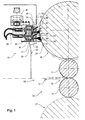
- Fig. 1 shows a rolling stand 10 with two work rolls 11, 12 between which a roll gap 13 is formed, through which a rolled strip 14 is conveyed in the direction of strip 15.
- the work rolls 11, 12 are arranged between two support rolls 16, 17, which are comparatively rigid with respect to the work rolls 11, 12 and support the latter along their bending line to a substantially constant nip 13 over the length of the work rolls 11, 12 form.
- a scraper unit 18 which is arranged in a machine frame 19 and is in the present case on a common to the rolling stand 10, not shown here base plate and thus defined relative to the roll stand 10 is positioned ,
- the scraper unit 18 comprises two stripping devices 20, 21 arranged one above the other, aligned parallel to the axis direction of the rollers in the rolling stand 10.
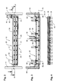
- the stripping devices 20, 21, which in a front view in FIG Fig. 2 are each shown a scraper 22, 23 with a rectangular profile 48 which are arranged in the longitudinal direction of the stripping means 20, 21.
- Both scrapers 22, 23 are arranged at an angle ⁇ inclined to the strip running direction 15 in the stripping devices 20, 21, such that by one of four longitudinal edges of the scrapers 22, 23 a rolling surface 24 closest stripping edge 25 and 26 is formed.
- the scrapers 22, 23 are each detachably connected to a base body 29, 30 of the respective scraper 22, 23 by means of a clamping strip 27, 28.
- Fig. 2 shows that in the present embodiment, the releasable connection of the terminal strips 27, 28 with the main bodies 29, 30 via screw 31 takes place.
- Each stripping device 20, 21 has a cleaning device 32, 33 which, like Fig. 1 shows, each formed in the main body 29, 30 nozzles 34 and a detergent supply line 35 which is connected to the main body 29, 30 and is connected via a cleaning agent channel 36 to the nozzle 34.
- Fig. 4 shows the nozzles 34 are arranged in the illustrated embodiment, that starting from a longitudinal direction of the Wiper 20, 21 center nozzle 34 to the axial ends of the stripping device 20, 21, the nozzles 34 are employed obliquely to the ends, wherein the nozzles 34 formed in use from cleaning fluid 47 spray cone 49.
- the stripping devices 20, 21 are arranged in a scraper frame 37 and are connected to the scraper frame 37 via piston rods 38 of piston / cylinder units 39. To relieve the piston rods 38 from transverse forces, the stripping devices 20, 21 are mounted in support guides 50 in the scraper frame 37.
- the scraper frame 37 is received on pins 40 on side walls 41, 42 of the machine frame 19 in the direction of a longitudinal axis 43 of the scraper device 20, 21 longitudinally displaceably mounted in both directions.
- a Oszilierantrieb 44 which includes a drive motor 45 which acts on a not shown here eccentric linkage 46 on the Abstreiferrahmen 37, with the result that the Abstreiferrahmen 37 with the drive motor 45 with the running in Fig. 2 drawn Oszillierhub H in the direction of the longitudinal axis 43 moves back and forth.
- FIG. 1 shown configuration shows the superimposed scraper devices 20, 21 in a rolling break, in which the scrapers 22, 23 with their scraping edges 25, 26 are spaced from the roll surface 24 of the support roller 16.
- no actual rolling takes place, so that during the rolling break no rolled strip 14 is conveyed through the nip 13 therethrough.
- this rolling break in which the rolling stand so quasi "empty" runs, can a cleaning of the scraping edges 25, 26 take place in that the scraping edges 25, 26 are moved by actuation of the piston / cylinder units 39 with construction of only slight contact pressure against the roll surface 24 and in this position the scraping edges 25, 26 through the nozzles 34th the cleaning means 32, 33 cleaning liquid 47 is sprayed onto the roll surface 24.
- the cleaning liquid 47 is transported by means of the rotating in the direction of rotation roller surface 24 against the voltage applied to the roll surface 24 Abstreifkanten 25, 26 and there on impurities, such as rolling abrasion, which are located on the scraping edge 25, 26 act.
- impurities such as rolling abrasion
- Fig. 1 it is also possible to align the nozzles 34 so that the cleaning liquid 47 does not act on the roll surface 24 of the support roller 16 via a drive, but rather directly on the scraping edges 25, 26 acts.
- FIG Fig. 1 a collecting channel 51 extending along the stripping means 20, 21, which decreases starting from the center of the roll toward the strip edges of the rolled strip 14, that is to say approximately in the shape of a roof ( Fig. 2 ), and serves to catch the coolant or lubricant dripping from the wipers 22, 23 and to dissipate laterally beyond the belt edges. This prevents dripping coolant or lubricant from getting onto the rolled strip 14.
- the collecting channel 51 serves to selectively remove the abrasion or the rolling flakes originating from the rolled strip 14 during the cleaning process.
- the scraping edges 25, 26 are moved against the roll surface 24 of the support roll 16 and are at a corresponding contact pressure against the roll surface 24 at.
- a relatively low contact pressure is initially generated by the piston / cylinder unit 39, which is steadily increased with increasing peripheral speed of the support roller 16.
Landscapes
- Engineering & Computer Science (AREA)
- Mechanical Engineering (AREA)
- Metal Rolling (AREA)
Abstract
Description
Die vorliegende Erfindung betrifft ein Verfahren zum Entfernen von Kühl- und/oder Schmiermittel von Walzen eines Walzgerüstes, in dem ein Walzband durch einen zwischen Arbeitswalzen gebildeten Walzspalt in Bandlaufrichtung hindurch gefördert wird, wobei auf einer Einlaufseite und/oder einer Auslaufseite des Walzgerüstes zumindest eine Abstreifeinrichtung mit einer Abstreifkante mit Kontaktdruck gegen eine Walzenoberfläche einer Arbeitswalze oder einer die Arbeitswalze im Walzgerüst stützenden Stützwalze anliegt. Darüber hinaus betrifft die Erfindung eine Vorrichtung zur Durchführung des Verfahrens.The present invention relates to a method for removing coolant and / or lubricant from rolls of a roll stand, in which a rolled strip is conveyed through a roll gap formed between work rolls in the strip running direction, wherein at least one stripping device on an inlet side and / or an outlet side of the rolling stand with a scraping edge with contact pressure against a roll surface of a work roll or a work roll supporting the roll stand in the roll stand. Moreover, the invention relates to a device for carrying out the method.
Zur Kühlung oder zur Schmierung der Walzenoberflächen von Arbeits- und/oder Stützwalzen werden Walzgerüste, in denen vorgenannte Walzen angeordnet sind, mit Einrichtungen versehen, die eine Beaufschlagung der Walzenoberflächen mit Kühl- und/oder Schmiermittel ermöglichen. So ist es beispielsweise aus der
Grundsätzlich ist eine auslaufseitige Oberflächenbelegung der Walzbandoberfläche mit Schmiermittel zu vermeiden, da mit der Entfernung dieses Oberflächenbelags ein erheblicher Aufwand verbunden ist. In der Praxis ist es bislang regelmäßig notwendig, eine Entfernung entsprechender Schmiermittelrückstände auf der Walzbandoberfläche durch eine dem Walzvorgang nachfolgende Glühbehandlung des Walzbandes zu entfernen. Hiermit ist ein erheblicher Energiebedarf verbunden, der einen entsprechenden Anteil der Herstellungskosten des Walzbandes ausmacht.In principle, an outlet-side surface covering of the rolled strip surface with lubricant is to be avoided, since a considerable outlay is associated with the removal of this surface covering. In practice, it has hitherto been regularly necessary to remove a removal of corresponding lubricant residues on the rolled strip surface by means of an annealing treatment of the rolled strip following the rolling process. This is associated with a significant energy demand, which makes up a corresponding proportion of the production costs of the rolled strip.
Mit den bekannten Abstreifervorrichtungen soll eine auslaufseitige Belegung der Walzbandoberfläche mit Schmiermittel soweit wie möglich reduziert werden, um den nachfolgend betriebenen Entfettungsaufwand, beispielsweise durch Glühen, entsprechend reduzieren zu können.With the known Abstreifervorrichtungen an outlet side occupancy of the rolled strip surface with lubricant should be reduced as much as possible in order to reduce the subsequently operated degreasing effort, for example by annealing, according to.
In der Praxis ist man daher dazu übergegangen, die Abstreifeinrichtungen, die als sogenannte Abstreiferlippen ausgebildet unter Druck gegen die Walzenoberfläche der betreffenden Walzen anliegen, mit einem so hohen Kontaktdruck gegen die Walzenoberflächen zu pressen, dass ein wirkungsvolles Abstreifen von Schmiermittel von der Walzenoberfläche sichergestellt ist. Die dabei eingestellten Anpressdrücke sind oftmals so hoch, dass es zu einem erhöhten Verschleiß der Abstreiferlippen kommt. Darüber hinaus treten aufgrund des konstant eingestellten Anpressdruckes, der unabhängig von der Walzendrehzahl in jedem Fall ein sicheres Abstreifen ermöglichen soll, bei sehr niedrigen Walzendrehzahlen, also insbesondere beim Anfahren des Walzen und beim Abbremsen der Walzen, Pfeif- oder Quietschgeräusche auf, die eine erhebliche Lärmemission darstellen.In practice, therefore, it has begun to press the stripping devices, which are designed as so-called wiper lips under pressure against the roll surface of the respective rollers, with such a high contact pressure against the roll surfaces, that an effective stripping of lubricant is ensured by the roll surface. The contact pressures set are often so high that increased wear of the wiper lips occurs. In addition, due to the constant set contact pressure, which is to allow independent of the roller speed in each case a safe stripping, at very low rolling speeds, ie in particular when starting the rolling and braking the rollers, whistling or squeaking, which is a significant noise emission represent.
Das Bedienungspersonal der Walzgerüste geht daher häufig dazu über, während des Beschleunigens und Abbremsens der Walzen im Walzgerüst die Abstreiferlippen nicht gegen die Walzenoberfläche anliegen zu lassen, mit der Folge, dass während dieser Phasen erhöhte Ölbelegungen auf der Auslaufseite entstehen. Diese unstetige Ölbelegung der Walzbandoberfläche führt dazu, dass sich bedingt durch den nachfolgenden Glühvorgang auf der Walzbandoberfläche oftmals Verfärbungen ausbilden, die entsprechende Walzbandabschnitte zu Ausschuss machen.The operator of the rolling stands is therefore often on, during the acceleration and deceleration of the rollers in the rolling stand, the wiper lips do not rest against the roll surface, with the result that during these phases increased oil deposits on the outlet side arise. This unsteady oil occupancy of the rolled strip surface causes due to the subsequent annealing on the rolled strip surface often form discolorations that make corresponding rolled strip sections to committee.
Der vorliegenden Erfindung liegt daher die Aufgabe zugrunde, ein Verfahren bzw. eine Vorrichtung vorzuschlagen, das bzw. die zuverlässig zu einer weitestgehenden Vermeidung einer Ölbelegung der Walzbandoberfläche auf der Auslaufseite eines Walzgerüsts beiträgt.The present invention is therefore based on the object to propose a method or a device which reliably contributes to a largely avoidance of oil occupation of the rolled strip surface on the outlet side of a rolling stand.
Diese Aufgabe wird durch ein Verfahren mit den Merkmalen des Anspruchs 1 gelöst.This object is achieved by a method having the features of claim 1.
Bei dem erfindungsgemäßen Verfahren zum Entfetten von Kühl- und/oder Schmiermittel von Walzen eines Walzgerüstes wird der Kontaktdruck, mit dem die Abstreifkante der Abstreifeinrichtung gegen eine Walzenoberfläche einer Arbeitswalze oder einer die Arbeitswalze im Walzgerüst stützenden Stützwalze anliegt, in Abhängigkeit von einem Betriebsparameter des Walzvorgangs verändert. In Abhängigkeit von der Gestaltung und oder dem Material der Abstreifer ist es nicht in jedem Fall notwendig eine Abstreifkante auszubilden, so das in den entsprechenden Fällen auch eine eher flächige Anlage der Abstreifer gegen die Walzenoberfläche im Sinne eine Abstreiffläche ausgebildet sein kann. Der Begriff "Abstreifkante" ist daher nicht eingeschränkt dahingehend zu verstehen, dass zwischen dem Abstreifer und der Walzenoberfläche in jedem Fall ein Linienkontakt ausgebildet ist.In the method according to the invention for degreasing the coolant and / or lubricant of rolls of a roll stand, the contact pressure with which the scraping edge of the stripper abuts against a roll surface of a work roll or a support roll supporting the work roll in the rolling stand is changed as a function of an operating parameter of the rolling process , Depending on the design and / or the material of the scraper, it is not always necessary to form a scraper edge, so that in the corresponding cases, a rather flat contact of the scrapers against the roll surface in the sense of a scraper surface can be formed. The term "wiper edge" is therefore not to be understood as limited in that a line contact is formed between the wiper and the roller surface in each case.
Bei diesem Betriebsparameter, der die Wirkung der Abstreifeinrichtung beeinflusst, handelt es sich vorzugsweise um die Walzenumfangsgeschwindigkeit, mit der die betreffenden Walzen, also die Walzen, gegen die die Abstreifeinrichtung anliegt, rotieren. Abgesehen davon, kann es sich natürlich auch um andere Betriebsparameter handeln, wie insbesondere auch die Temperatur der betreffenden Walze bzw. Walzenoberfläche, die Rauhigkeit oder Balligkeit der Walzenoberfläche. Unter Betriebsparameter sind somit alle den Walzvorgang bzw. das Ergebnis des Walzvorgangs beeinflussenden Parameter zu verstehen, die gleichzeitig auch eine Auswirkung auf die Wirksamkeit der Abstreifeinrichtung haben.In this operating parameter, which affects the action of the stripping, it is preferably the roller peripheral speed at which the respective rollers, ie the rollers against which abuts the wiper, rotate. Apart from that, it can of course also be other operating parameters, in particular the temperature of the respective roller or roller surface, the roughness or crowning of the roller surface. Operating parameters are thus to be understood as all parameters influencing the rolling process or the result of the rolling process, which at the same time also have an effect on the effectiveness of the stripping device.
Besonders unmittelbar wird jedoch der positive Effekt einer Veränderung des Kontaktdrucks deutlich, wenn diese Veränderung in Abhängigkeit von der Walzenumfangsgeschwindigkeit erfolgt. Die Verwendung des Parameters "Walzenumfangsgeschwindigkeit" als Stellgröße für eine entsprechende Andrucksteuerung oder Andruckregelung, beruht auf der Erkenntnis, dass beispielsweise bei einem Anfahrvorgang, also bei relativ geringer Walzenumfangsgeschwindigkeit, ein entsprechend niedriger Kontaktdruck ausreichend ist, um einen sicheren Abstreifeffekt zu erzielen. Andererseits ist es bei höherer Walzenumfangsgeschwindigkeit notwendig, den Kontaktdruck zu erhöhen, um beispielsweise Aquaplaningeffekte, also ein Aufschwimmen der Abstreifeinrichtung auf einem auf der Walzenoberfläche ausgebildeten Schmiermittelfilm verhindern zu können. Die Folge eines derartigen Aufschwimmens ist nämlich, dass das Schmiermittel die Abstreifeinrichtung in unerwünschter Weise passieren und somit auf die Auslaufseite des Walzgerüstes und damit auf die auslaufseitige Walzbandoberfläche gelangen kann.However, the positive effect of a change in the contact pressure becomes particularly immediately apparent if this change takes place as a function of the peripheral roll speed. The use of the parameter "roll peripheral speed" as a control variable for a corresponding Andrucksteuerung or pressure control, based on the finding that, for example, in a start-up, so at relatively low roller peripheral speed, a correspondingly low contact pressure is sufficient to achieve a secure wiping effect. On the other hand, it is necessary at higher roller circumferential speed to increase the contact pressure in order to prevent, for example, aquaplaning effects, ie, a floating of the stripping device on a lubricant film formed on the roller surface. The consequence of such floating is namely that the lubricant can pass the stripping device in an undesired manner and thus reach the outlet side of the rolling stand and thus the outlet side rolled strip surface.
Betrachtet man den gesamten Walzvorgang, also beginnend mit einer Anfahrphase bis hin zu einer Abbremsphase nachfolgend einer stationären Betriebsphase, in der die Walzen im Walzgerüst mit konstanter Drehzahl rotieren, so erweist es sich für die Praxis als besonders vorteilhaft, wenn bei einer Erhöhung der Walzenumfangsgeschwindigkeit der Kontaktdruck erhöht und bei einer Reduzierung der Walzenumfangsgeschwindigkeit der Kontaktdruck entsprechend reduziert wird.Considering the entire rolling process, so starting with a start-up phase to a deceleration phase following a stationary operating phase in which the rollers rotate in the rolling mill at a constant speed, it proves to be particularly advantageous in practice, when an increase in the roller peripheral speed of Increased contact pressure and with a reduction in the roller circumferential speed of the contact pressure is reduced accordingly.
Dabei kann grundsätzlich so verfahren werden, dass hinsichtlich der Einstellung des Kontaktdrucks mit festen Druckstufen gearbeitet wird, wobei es sich jedoch als besonders vorteilhaft erweist, wenn in Abhängigkeit von der Walzenumfangsgeschwindigkeit eine stetige Veränderung des Kontaktdrucks erfolgt.In principle, it is possible to proceed in such a way that fixed pressure steps are used with regard to the setting of the contact pressure, although it proves to be particularly advantageous if a continuous change in the contact pressure occurs as a function of the roller circumferential speed.
Insbesondere um nicht nur Betriebsparameter des Walzgerüstes, sondern auch Betriebsparameter weiterer am Walzvorgang beteiligter Aggregate und Einrichtungen mit einzubeziehen, erweist es sich als vorteilhaft, wenn als weiterer Parameter bei der Veränderung des Kontaktdrucks ein Material- oder Formparameter der Abstreifereinrichtung verwendet wird. So ist es beispielsweise möglich, bei der Veränderung des Kontaktdrucks die Elastizität der Abstreifkanten zu berücksichtigen.In particular, in order not only to include operating parameters of the mill stand, but also operating parameters of other aggregates and devices involved in the rolling process, it proves to be advantageous if a material or shape parameter of the stripping device is used as a further parameter when changing the contact pressure. For example, it is possible to take into account the elasticity of the scraping edges when changing the contact pressure.
Eine weitere Optimierung des Verfahrens kann erfolgen, wenn als weiterer Parameter bei der Veränderung des Kontaktdrucks ein Material- oder Form- bzw. Oberflächenparameter der mit der Abstreifeinrichtung zusammen wirkenden Walze verwendet wird, so dass es beispielsweise auch denkbar ist, in Abhängigkeit von einer Walzenballigkeit den von der Abstreifkante auf die Walzenoberfläche wirkenden Kontaktdruck längs der Walzenachse unterschiedlich auszubilden.A further optimization of the method can take place if a material or shape or surface parameter of the roller cooperating with the stripping device is used as a further parameter in the change of the contact pressure, so that it is also conceivable, for example, depending on a roll crown form the contact pressure acting along the roll axis of the wiping edge on the roll surface differently.
Weiterhin kann es sich als vorteilhaft erweisen, wenn als weiterer Parameter bei der Veränderung des Kontaktdrucks ein durch das Kühl-/Schmiermittel bestimmter Parameter verwendet wird. Beispielsweise können derartige Parameter in der Beschaffenheit bzw. der Zusammensetzung des Schmiermittels oder auch in der Schmiermittelmenge begründet sein, so dass etwa der Kontaktdruck in weiterer Abhängigkeit von der Viskosität des Schmiermittels verändert wird.Furthermore, it may prove advantageous if, as a further parameter in the change of the contact pressure, a parameter determined by the coolant / lubricant is used. For example, such parameters may be due to the nature or the composition of the lubricant or in the amount of lubricant, so that about the contact pressure is changed in further dependence on the viscosity of the lubricant.
Eine weitere Erhöhung der Wirksamkeit der Abstreifeinrichtung lässt sich erzielen, wenn während einer Walzpause, in der der eigentliche Produktionsvorgang, bei dem Walzband durch den Walzspalt hindurch gefördert wird, ausgesetzt ist, die Abstreifeinrichtung mittels einer der Abstreifeinrichtung zugeordneten Reinigungseinrichtung gereinigt wird.A further increase in the effectiveness of the stripping device can be achieved if, during a rolling break in which the actual production process, in the rolled strip through the nip is conveyed is exposed, the stripping device is cleaned by means of a stripping device associated cleaning device.
Beispielsweise kann mittels der der Abstreifeinrichtung zugeordneten Reinigungseinrichtung während der Walzpause ein Reinigungsmedium auf die Abstreifeinrichtung bzw. insbesondere die Abstreifkante der Abstreifereinrichtung aufgebracht werden. Hierzu kann sich bereits eine entsprechend ausgerichtete Luftströmung oder ein flüssiges Reinigungsmittel eignen. Als Reinigungsmittel kann vorteilhaft dasselbe Medium wie zum Schmieren und/oder Kühlen der Walzen verwendet werden. Mittels einer entsprechenden Reinigungseinrichtung können somit insbesondere sogenannte "Walzflitter" oder ein vom Walzband stammender Abrieb, von der Abstreifkante entfernt werden, um eine von entsprechenden Verunreinigungen befreite Oberfläche für den Abstreifvorgang während der Produktion zur Verfügung zu stellen.For example, a cleaning medium can be applied to the stripping device or in particular the stripping edge of the stripping device by means of the cleaning device assigned to the stripping device during the rolling break. For this purpose, a suitably aligned air flow or a liquid detergent may already be suitable. As the cleaning agent can be advantageously used the same medium as for lubricating and / or cooling the rollers. By means of a corresponding cleaning device, in particular so-called "rolling flakes" or abrasion originating from the rolled strip, can thus be removed from the wiping edge in order to provide a surface for the stripping process which is freed from corresponding impurities during production.
Als besonders vorteilhaft erweist es sich, wenn bei der Reinigung die Abstreifkante zusätzlich zu einer Beaufschlagung der Abstreifkante mit einem Reinigungsmedium mit mechanischen Schwingungen beaufschlagt wird, die eine Schwerkraftreinigung der Abstreifkante ermöglichen.It proves to be particularly advantageous if, during cleaning, the wiping edge, in addition to being exposed to the wiping edge, is acted upon by a cleaning medium with mechanical oscillations, which enable a gravity cleaning of the wiping edge.
Die erfindungsgemäße Vorrichtung weist die Merkmale des Anspruchs 12 auf.The device according to the invention has the features of
Bei der erfindungsgemäßen Vorrichtung ist eine der Abstreifeinrichtung zugeordnete Andruckeinrichtung vorgesehen, die zumindest ein Andruckmittel zur Beaufschlagung der Abstreifeinrichtung mit einer Druckkraft aufweist, derart, dass die Abstreifkante der Abstreifeinrichtung mit einem Kontaktdruck gegen die Walzenoberfläche der Arbeitswalze oder einer die Arbeitswalze im Walzgerüst stützenden Stützwalze anliegt, wobei der Andruckeinrichtung eine Steuer-/Regeleinrichtung zugeordnet ist, die in Abhängigkeit von einem Betriebsparameter des Walzvorgangs das Andruckmittel mit einer Stellgröße beaufschlagt, derart, dass die Abstreifkante mit einem definierten Kontaktdruck gegen die Walzenoberfläche anliegt.In the apparatus according to the invention a stripping device associated pressing device is provided which has at least one pressing means for acting on the stripping with a compressive force, such that the stripping edge of the stripping abuts with a contact pressure against the roll surface of the work roll or a work roll in the roll stand supportive support roller wherein the pressure device is associated with a control / regulating device which acts on the pressing means in response to an operating parameter of the rolling process with a manipulated variable, in such a way that the scraping edge bears against the roll surface with a defined contact pressure.
Diese Stellgröße kann beispielsweise als Weggröße, Druck oder auch als elektrische Spannung ausgebildet sein, die sich in Abhängigkeit von dem Betriebsparameter, also beispielsweise der Walzenumfangsgeschwindigkeit, ändert.This manipulated variable may be formed, for example, as a path, pressure or as electrical voltage, which changes depending on the operating parameters, so for example, the roller peripheral speed.
Für die Effektivität der Abstreifeinrichtung hat es sich als besonders vorteilhaft herausgestellt, wenn die Abstreifeinrichtung so am Walzgerüst angeordnet ist, dass sie mit der oberen und/oder unteren Stützwalze zusammenwirkt.For the effectiveness of the stripping, it has been found to be particularly advantageous if the stripping device is arranged on the rolling mill, that it cooperates with the upper and / or lower support roller.
Eine weitere Steigerung der Effektivität lässt sich erzielen, wenn das Walzgerüst sowohl auf der Einlaufseite als auch auf der Auslaufseite mit einer der oberen und/oder unteren Stützwalze zugeordneten Abstreifeinrichtung versehen ist.A further increase in effectiveness can be achieved if the rolling stand is provided on both the inlet side and on the outlet side with one of the upper and / or lower support roller associated scraper.
Wenn die Abstreifeinrichtung zumindest einen Abstreifer aufweist, der ein Rechteckprofil aufweist und unter einem Anstellwinkel zur Bandlaufrichtung in der Abstreifeinrichtung aufgenommen ist, derart, dass die Abstreifkante durch eine Längskante des Abstreifers gebildet ist, ist einerseits eine leicht reproduzierbare Abstreifkante ausgebildet. Andererseits werden somit von nur einem Abstreifer vier Abstreifkanten bereitgestellt.If the stripping device has at least one scraper, which has a rectangular profile and is received at an angle of attack to the strip running direction in the stripping device, such that the stripping edge is formed by a longitudinal edge of the scraper, on the one hand an easily reproducible scraper edge is formed. On the other hand, four stripping edges are thus provided by only one scraper.
Eine derartige multiple Ausbildung von Abstreifkanten an lediglich einem Abstreifer lässt sich besonders vorteilhaft nutzen, wenn der Abstreifer austauschbar in der Abstreifeinrichtung aufgenommen ist, derart, dass durch geeignete Wendevorgänge des einen Abstreifers nacheinander alle vier Abstreifkanten nutzbar sind.Such a multiple formation of scraping edges on only one scraper can be used particularly advantageously when the scraper is exchangeably received in the stripping device, such that by suitable turning operations of a scraper successively all four stripping edges are available.
Besonders vorteilhaft ist es, wenn zur Erhaltung der Wirksamkeit der Abstreifeinrichtung die Abstreifeinrichtung mit einer Reinigungseinrichtung versehen ist.It is particularly advantageous if, in order to maintain the effectiveness of the stripping device, the stripping device is provided with a cleaning device.
Diese Reinigungseinrichtung kann mit Mitteln zur Beaufschlagung der Abstreifeinrichtung bzw. der Abstreifkante mit einem Reinigungsmedium versehen sein, wobei vorzugsweise zusätzlich die Reinigungseinrichtung neben Mitteln zur Beaufschlag mit der Abstreifkante mit einem Reinigungsmedium ein Schwingungserzeuger aufweist, der die Abstreifeinrichtung in mechanische Schwingungen oder Bewegungen, vorzugsweise in Walzenachsenrichtung bzw. in Längsrichtung der Abstreifer, versetzt. Beispielsweise kann der Schwingungserzeuger einen in Längsachsenrichtung der Abstreifeinrichtung bzw. der betreffenden Walze die Abstreifeinrichtung mit hin und her gehenden Exzenterantrieb aufweisen.This cleaning device may be provided with means for acting on the stripping device or the stripping edge with a cleaning medium, wherein preferably in addition to the cleaning means in addition to means for loading the scraping edge with a cleaning medium comprises a vibration generator, the stripping in mechanical vibrations or movements, preferably in the roll axis direction or in the longitudinal direction of the scraper, offset. For example, the vibration generator may have a scraper device with reciprocating eccentric drive in the longitudinal axis direction of the stripping device or the respective roller.
Nachfolgend wird eine bevorzugte Variante des Verfahrens anhand des Betriebs einer Ausführungsform der Vorrichtung unter Bezugnahme auf die Zeichnung näher erläutert. Es zeigen:
- Fig. 1:
- die Einlaufseite eines Walzgerüstes mit einem einer Stützwalze zugeordnetem Abstreiferaggregat;
- Fig. 2:
- eine Frontansicht des in
Fig. 1 dargestellten Abstreiferaggregats; - Fig. 3:
- eine Schnittdarstellung des in
Fig. 2 dargestellten Abstreiferaggregats längs Schnittlinienverlauf III-III inFig. 2 ; - Fig. 4:
- eine Schnittdarstellung durch eine Reinigungseinrichtung der im Abstreiferaggregat angeordneten Abstreifeinrichtung längs Schnittlinienverlauf IV-IV in
Fig. 2
- Fig. 1:
- the inlet side of a roll stand with a backing roll associated Abstreiferaggregat;
- Fig. 2:
- a front view of the in
Fig. 1 shown Abstreiferaggregats; - 3:
- a sectional view of the in
Fig. 2 shown Abstreiferaggregats along section line III-III inFig. 2 ; - 4:
- a sectional view through a cleaning device of the scraper arranged in Abstreiferaggregat along section line IV-IV in
Fig. 2
Wie weiter in
Das Abstreiferaggregat 18 umfasst im vorliegenden Fall zwei übereinanderliegend angeordnete, parallel zur Achsenrichtung der Walzen im Walzgerüst 10 ausgerichtete Abstreifeinrichtungen 20, 21. Die Abstreifeinrichtungen 20, 21, die in einer Frontansicht in
Wie
Wie
Wie insbesondere aus einer Zusammenschau der
Wie
Nachfolgend wird der Betrieb des in den
Die in
Unterhalb der Abstreifer 22, 23 befindet sich gemäß der Darstellung in
Während des Walzvorgangs sind die Abstreifkanten 25, 26 gegen die Walzenoberfläche 24 der Stützwalze 16 verfahren und liegen mit entsprechendem Kontaktdruck gegen die Walzenoberfläche 24 an. Dabei erfolgt sowohl das Verfahren der Abstreifkanten 25, 26 gegen die Walzenoberfläche 24 als auch die Ausbildung bzw. Einstellung des Kontaktdrucks über entsprechende Verfahr- oder Zustellbewegungen der Kolben/Zylinder-Einheiten 39. Bei einem Anfahrvorgang zu Beginn des Walzzyklus wird durch die Kolben/Zylinder-Einheit 39 zunächst ein relativ geringer Kontaktdruck erzeugt, der mit steigender Umfangsgeschwindigkeit der Stützwalze 16 stetig erhöht wird. Im stationären Betrieb des Walzgerüstes bleibt der Kontaktdruck im Wesentlichen unverändert, um dann schließlich bei einem Abbremsen des Walzgerüstes, also bei sich verringernder Walzenumfangsgeschwindigkeit, eine entsprechende Rückstellbewegung der Kolben/Zylinder-Einheiten 39 vorzugsweise proportional zur Geschwindigkeitsreduzierung, abgebaut zu werden.During the rolling process, the scraping edges 25, 26 are moved against the
Neben der eingangs erwähnten Beaufschlagung der Walzenoberfläche 24 der Stützwalze 16 mit Reinigungsflüssigkeit 47 während der Walzpause, oder auch in Ausnahmefällen während des Walzbetriebs, kann zusätzlich in der Walzpause auch eine mechanische Reinigung der Abstreifkanten 25, 26 dadurch erfolgen, dass die Abstreifkanten 25, 26 unter vergleichsweise geringem Kontaktdruck gegen die Walzenoberfläche 24 anliegen und gleichzeitig eine Beaufschlagung des Abstreiferrahmens 37 mit oszilierenden Längsschwingungen mittels des Oszilierantriebs 44 erfolgt, derart, dass die Abstreifkanten 25, 26 während des Anliegens gegen die rotierende Walzenoberfläche 24 mit längs den Walzenachsen gerichteten Schwingungen beaufschlagt werden. Dadurch können auf den Abstreifkanten 25, 26 befindliche Verunreinigungen durch entsprechend induzierte Walkbewegungen der Abstreifkanten 25, 26 auf der Walzenoberfläche 24 von den Abstreifkanten 25, 26 entfernt werden.In addition to the initially mentioned action on the
Claims (20)
dadurch gekennzeichnet,
das der Kontaktdruck in Abhängigkeit von einem Betriebsparameter des Walzvorgangs verändert wird.Method for removing coolant and / or lubricant from rolls of a roll stand (10), in which a rolled strip (14) is conveyed through a roll gap (13) formed between work rolls (1, 12) in the strip running direction (15) an inlet side and / or an outlet side of the roll stand at least one stripping (20, 21) with a scraper edge (25, 26) with contact pressure against a roll surface (24) of a work roll or the work roll in the roll stand supportive support roller (16, 17) is present,
characterized,
that the contact pressure is changed depending on an operating parameter of the rolling process.
dadurch gekennzeichnet,
dass der Kontaktdruck in Abhängigkeit von der Walzenumfangsgeschwindigkeit verändert wird.Method according to claim 1,
characterized,
that the contact pressure is changed depending on the roller peripheral speed.
dadurch gekennzeichnet,
dass bei einer Erhöhung der Walzenumfangsgeschwindigkeit der Kontaktdruck erhöht und bei einer Reduzierung der Walzenumfangsgeschwindigkeit der Kontakt reduziert wird.Method according to claim 2,
characterized,
that as the roller peripheral speed is increased, the contact pressure is increased and the contact is reduced as the roller peripheral speed is reduced.
dadurch gekennzeichnet,
dass in Abhängigkeit von der Walzenumfangsgeschwindigkeit eine stetige Veränderung des Kontaktdrucks erfolgt.Method according to claim 3,
characterized,
in that a constant change in the contact pressure takes place as a function of the roller circumferential speed.
dadurch gekennzeichnet,
dass in Abhängigkeit von der Walzenumfangsgeschwindigkeit eine unstetige, insbesondere abgestufte Veränderung des Kontaktdrucks erfolgt.Method according to claim 3,
characterized,
in that a discontinuous, in particular graduated, change in the contact pressure takes place as a function of the roller circumferential speed.
dadurch gekennzeichnet,
dass als weitere Parameter bei der Veränderung des Kontaktdrucks ein Material- oder Formparameter der Abstreifeinrichtung (20, 21) verwendet wird.Method according to one of the preceding claims,
characterized,
that a material or shape parameter of the stripping device (20, 21) is used as further parameters when changing the contact pressure.
dadurch gekennzeichnet,
dass als weiterer Parameter bei der Veränderung des Kontaktdrucks ein Material- oder Formparameter der mit der Abstreifeinrichtung (20, 21) zusammenwirkenden Walze verwendet wird.Method according to one or more of the preceding claims,
characterized,
that a material or shape parameter of the roller cooperating with the stripping device (20, 21) is used as a further parameter in the change of the contact pressure.
dadurch gekennzeichnet,
dass als weiterer Parameter bei der Veränderung des Kontaktdrucks ein durch das Kühl-/Schmiermittel bestimmter Parameter verwendet wird.Method according to one or more of the preceding claims,
characterized,
that as another parameter in changing the contact pressure a parameter determined by the coolant / lubricant is used.
dadurch gekennzeichnet,
dass die Abstreifeinrichtung (20, 21) oder die der Abstreifeinrichtung gegenüberliegende Walzenoberfläche (24) während einer Walzpause mittels einer der Abstreifeinrichtung zugeordneten Reinigungseinrichtung (32, 33) gereinigt wird.Method according to one of the preceding claims,
characterized,
that the stripping device (20, 21) or the roller surface (24) opposite the stripping device is cleaned during a rolling break by means of a cleaning device (32, 33) associated with the stripping device.
dadurch gekennzeichnet,
dass die Abstreifeinrichtung (20, 21) oder die Walzenoberfläche (24) während einer Walzpause mittels der Reinigungseinrichtung (32, 33) mit einem Reinigungsmedium beaufschlagt wird.Method according to claim 9,
characterized,
that the stripping device (20, 21) or the roller surface (24) is acted upon by a cleaning medium during a rolling break by means of the cleaning device (32, 33).
dadurch gekennzeichnet,
dass die Abstreifeinrichtung (20, 21) während einer Walzpause in Längsrichtung der Abstreifkanten (25, 26) mit Schwingungen beaufschlagt wird.Method according to claim 9 or 10,
characterized,
in that the stripping device (20, 21) is subjected to vibrations during a rolling break in the longitudinal direction of the scraping edges (25, 26).
dass der Andruckeinrichtung einer Steuer-/Regeleinrichtung zugeordnet ist, die in Abhängigkeit von einem Betriebsparameter des Walzvorgangs das Andruckmittel mit einer Stellgröße beaufschlagt, derart, dass die Abstreifkante mit einem definierten Kontaktdruck gegen die Walzenoberfläche anliegt.Apparatus for removing coolant and / or lubricant from rolls of a roll stand (10), in which a rolled strip (14) is conveyed through a roll gap (13) formed between work rolls (11, 12) in the strip running direction (15), with at least a stripping device (20, 21) arranged on an inlet side and / or outlet side of the rolling stand with a stripping edge (25, 26) extending transversely to the strip running direction (15), a pressure device associated with the stripping device with at least one pressure means for applying a pressure force to the stripping device in that the scraping edge of the stripping device is in contact with a roller surface (24) of the work roll and / or one of the work rolls in the roll stand supporting the support roller (16, 17) is applied, characterized
that the pressure device is associated with a control / regulating device which acts on the pressure means in response to an operating parameter of the rolling process with a manipulated variable, such that the wiper edge rests against the roller surface with a defined contact pressure.
dadurch gekennzeichnet,
dass die Abstreifeinrichtung (20, 21) so am Walzgerüst (10) angeordnet ist, dass sie mit der oberen und/oder unteren Stützwalze (16, 17) zusammenwirkt.Device according to claim 12,
characterized,
in that the stripping device (20, 21) is arranged on the rolling stand (10) in such a way that it cooperates with the upper and / or lower support roller (16, 17).
dadurch gekennzeichnet,
dass das Walzgerüst (10) sowohl auf der Einlaufseite als auch auf der Auslaufseite eine der oberen und/oder unteren Stützwalze (16, 17) zugeordnete Abstreifeinrichtung (20, 21) aufweist.Device according to claim 13,
characterized,
in that the rolling stand (10) has a stripping device (20, 21) associated with both the inlet side and the outlet side of the upper and / or lower support roller (16, 17).
dadurch gekennzeichnet,
dass die Abstreifeinrichtung (20, 21) zumindest einen Abstreifer (22, 23) aufweist, der ein Profil mit einer Mehrzahl von parallel verlaufenden Längskanten aufweist und unter einem Anstellwinkel α zur Bandlaufrichtung (15) in der Abstreifeinrichtung aufgenommen ist, derart, dass die Abstreifkante (25, 26) durch eine Längskante des Abstreifers gebildet ist.Device according to one of claims 12 to 14,
characterized,
in that the stripping device (20, 21) has at least one scraper (22, 23) which has a profile with a plurality of parallel longitudinal edges and is received in the stripping device at an angle α to the strip running direction (15), such that the scraper edge (25, 26) is formed by a longitudinal edge of the scraper.
dadurch gekennzeichnet,
dass der Abstreifer (22, 23) ein Rechteckprofil aufweist.Device according to claims 15,
characterized,
that the scraper (22, 23) has a rectangular profile.
dadurch gekennzeichnet,
dass der Abstreifer (22, 23) austauschbar in der Abstreifeinrichtung (20, 21) aufgenommen ist.Device according to claim 15 or 16,
characterized,
that the scraper (22, 23) are interchangeable in the stripping means (20, 21) is accommodated.
dadurch gekennzeichnet,
dass die Abstreifeinrichtung (20, 21) mit einer Reinigungseinrichtung (32, 33) versehen ist.Device according to one of claims 12 to 17,
characterized,
that the stripping device is provided (20, 21) with a cleaning device (32, 33).
dadurch gekennzeichnet,
dass die Reinigungseinrichtung (32, 3) Mittel zur Beaufschlagung der Abstreifkante (25, 26) oder der Walzenoberfläche (24) mit einem Reinigungsmedium aufweist.Device according to claim 18,
characterized,
in that the cleaning device (32, 3) has means for acting on the wiping edge (25, 26) or the roller surface (24) with a cleaning medium.
dadurch gekennzeichnet,
dass die Absteifeinrichtung (20, 21) einen Schwingungserzeuger aufweist zur Beaufschlagung der Abstreifer (22, 23) mit Schwingungen in Längsrichtung der Abstreifer.Device according to claim 18 or 19,
characterized,
in that the stiffening device (20, 21) has a vibration generator for acting on the wipers (22, 23) with vibrations in the longitudinal direction of the wipers.
Applications Claiming Priority (1)
| Application Number | Priority Date | Filing Date | Title |
|---|---|---|---|
| DE201010028609 DE102010028609B4 (en) | 2010-05-05 | 2010-05-05 | Method and device for removing coolant and / or lubricant from rolls of a roll stand |
Publications (2)
| Publication Number | Publication Date |
|---|---|
| EP2384829A1 true EP2384829A1 (en) | 2011-11-09 |
| EP2384829B1 EP2384829B1 (en) | 2013-08-28 |
Family
ID=44486970
Family Applications (1)
| Application Number | Title | Priority Date | Filing Date |
|---|---|---|---|
| EP20110159788 Active EP2384829B1 (en) | 2010-05-05 | 2011-03-25 | Method of and device for removing coolant and/or lubricant from rollers of a roller framework according to a use parameter of the rolling process |
Country Status (2)
| Country | Link |
|---|---|
| EP (1) | EP2384829B1 (en) |
| DE (1) | DE102010028609B4 (en) |
Cited By (4)
| Publication number | Priority date | Publication date | Assignee | Title |
|---|---|---|---|---|
| EP3284545A1 (en) | 2016-08-18 | 2018-02-21 | Primetals Technologies Austria GmbH | Scraper device for a rolling stand |
| CN110026438A (en) * | 2019-05-20 | 2019-07-19 | 安徽协同创新设计研究院有限公司 | A kind of copper strip mill roll cleaning device |
| CN114042768A (en) * | 2021-10-08 | 2022-02-15 | 中冶南方工程技术有限公司 | Strip steel oil removing method, strip steel oil removing device and rolling mill |
| WO2023165640A1 (en) * | 2022-03-04 | 2023-09-07 | Uvb Technik S.R.O. | Degreasing device |
Citations (5)
| Publication number | Priority date | Publication date | Assignee | Title |
|---|---|---|---|---|
| JPS5847310U (en) * | 1981-09-25 | 1983-03-30 | 住友金属工業株式会社 | Rolling oil removal equipment for lever mills |
| JPS63224807A (en) * | 1987-03-13 | 1988-09-19 | Kawasaki Steel Corp | Dewatering method for cooling water of rolling mill roll |
| JPH0631316A (en) * | 1992-07-21 | 1994-02-08 | Kawasaki Steel Corp | Hot rolling method by use of lubricant |
| WO2003002277A1 (en) * | 2001-06-28 | 2003-01-09 | Sms Demag Aktiengesellschaft | Method and device for cooling and lubricating rollers on a rolling stand |
| DE102007042898A1 (en) * | 2007-06-08 | 2008-12-11 | Sms Demag Ag | Method and device for roller lubrication |
Family Cites Families (2)
| Publication number | Priority date | Publication date | Assignee | Title |
|---|---|---|---|---|
| BE880892A (en) * | 1979-12-27 | 1980-06-27 | Cockerill | DEVICE AND METHOD FOR CONTINUOUS POLISHING AND FOR UNIFORMALLY COOLING THE TABLE OF A ROLLER ROLLER |
| DE20012091U1 (en) * | 2000-07-12 | 2000-12-28 | SWT Spann- u. Wickeltechnik Maschinenbau Engineering GmbH, 35764 Sinn | Scraper device for rollers with flexible pneumatic adjustment |
-
2010
- 2010-05-05 DE DE201010028609 patent/DE102010028609B4/en active Active
-
2011
- 2011-03-25 EP EP20110159788 patent/EP2384829B1/en active Active
Patent Citations (6)
| Publication number | Priority date | Publication date | Assignee | Title |
|---|---|---|---|---|
| JPS5847310U (en) * | 1981-09-25 | 1983-03-30 | 住友金属工業株式会社 | Rolling oil removal equipment for lever mills |
| JPS63224807A (en) * | 1987-03-13 | 1988-09-19 | Kawasaki Steel Corp | Dewatering method for cooling water of rolling mill roll |
| JPH0631316A (en) * | 1992-07-21 | 1994-02-08 | Kawasaki Steel Corp | Hot rolling method by use of lubricant |
| WO2003002277A1 (en) * | 2001-06-28 | 2003-01-09 | Sms Demag Aktiengesellschaft | Method and device for cooling and lubricating rollers on a rolling stand |
| EP1399277A1 (en) | 2001-06-28 | 2004-03-24 | SMS Demag Aktiengesellschaft | Method and device for cooling and lubricating rollers on a rolling stand |
| DE102007042898A1 (en) * | 2007-06-08 | 2008-12-11 | Sms Demag Ag | Method and device for roller lubrication |
Cited By (6)
| Publication number | Priority date | Publication date | Assignee | Title |
|---|---|---|---|---|
| EP3284545A1 (en) | 2016-08-18 | 2018-02-21 | Primetals Technologies Austria GmbH | Scraper device for a rolling stand |
| WO2018033305A1 (en) | 2016-08-18 | 2018-02-22 | Primetals Technologies Austria GmbH | Stripping device for a roll stand |
| US11370008B2 (en) | 2016-08-18 | 2022-06-28 | Primetals Technologies Austria GmbH | Stripping device for a roll stand |
| CN110026438A (en) * | 2019-05-20 | 2019-07-19 | 安徽协同创新设计研究院有限公司 | A kind of copper strip mill roll cleaning device |
| CN114042768A (en) * | 2021-10-08 | 2022-02-15 | 中冶南方工程技术有限公司 | Strip steel oil removing method, strip steel oil removing device and rolling mill |
| WO2023165640A1 (en) * | 2022-03-04 | 2023-09-07 | Uvb Technik S.R.O. | Degreasing device |
Also Published As
| Publication number | Publication date |
|---|---|
| DE102010028609B4 (en) | 2014-03-27 |
| DE102010028609A1 (en) | 2011-11-10 |
| EP2384829B1 (en) | 2013-08-28 |
Similar Documents
| Publication | Publication Date | Title |
|---|---|---|
| EP0230644B1 (en) | Arrangement for de-scaling hot-rolled steel bands | |
| WO2003002277A1 (en) | Method and device for cooling and lubricating rollers on a rolling stand | |
| EP3003589B1 (en) | Rolling device and method for conditioning a roll surface | |
| EP0367967A2 (en) | Method and device for cooling and lubricating cylinders and rolling stock during cold rolling | |
| EP2983863B1 (en) | Assembly and method for grinding a metal strip | |
| EP2384829B1 (en) | Method of and device for removing coolant and/or lubricant from rollers of a roller framework according to a use parameter of the rolling process | |
| EP2794137A1 (en) | Cleaning device and method for removing a lubricant from the rolls of a roll stand | |
| DE2842525C2 (en) | Method and device for producing a satined surface on a spherical roller by means of electrical discharge machining | |
| DE69316500T2 (en) | Rolling mill with crossed work rolls and rolling mill | |
| EP2644283B1 (en) | Coating system | |
| DE112005000112B4 (en) | Online grinding process for work roll | |
| EP1502670B1 (en) | Device for cleaning and polishing wire and for improving the quality of the wire for further processing | |
| DE112011105794T5 (en) | Surface treatment apparatus and surface treatment method for a long wire-shaped article | |
| EP1802406B1 (en) | Method and apparatus for cleaning rolls | |
| EP2359946A2 (en) | Hot rolling pilger mill train or hot rolling pilger mill respectively and method for operating a hot rolling pilger mill | |
| EP1579928B1 (en) | Process for removing scale or rust from a deformable metal stock | |
| EP1574286B1 (en) | Working method and device for the burnishing of gears | |
| DE102007053799A1 (en) | Anilox printing unit i.e. lithographic offset printing unit, operating method for printing image, involves evening out accumulation on screen roller such that accumulation pass through gap without contacting further roller | |
| DE19903928A1 (en) | Production of continuously cast slabs comprises using a solidifying cord shell in a cord guide extending from the mold to the final solidification point | |
| DE102012000485A1 (en) | Printing machine comprises screen roller and ink fountain with squeegee, where stripper is arranged in printing machine for stripping paint from leakage of squeegee | |
| DE10110026A1 (en) | Roll cleaning system for strip lines comprises straight or spiraled grooved roller in housing in roll contact area with grooves fed with regulatable cleaning fluid. | |
| WO2010028754A2 (en) | Descaling device | |
| DE10115993B4 (en) | Method for preventing the passage of liquids through the nip during the rolling of strips in strip rolling stands and apparatus for carrying out the method | |
| DE3900171C2 (en) | ||
| DE102004061080A1 (en) | Method and device for strip casting of metals |
Legal Events
| Date | Code | Title | Description |
|---|---|---|---|
| 17P | Request for examination filed |
Effective date: 20110415 |
|
| AK | Designated contracting states |
Kind code of ref document: A1 Designated state(s): AL AT BE BG CH CY CZ DE DK EE ES FI FR GB GR HR HU IE IS IT LI LT LU LV MC MK MT NL NO PL PT RO RS SE SI SK SM TR |
|
| AX | Request for extension of the european patent |
Extension state: BA ME |
|
| PUAI | Public reference made under article 153(3) epc to a published international application that has entered the european phase |
Free format text: ORIGINAL CODE: 0009012 |
|
| 17Q | First examination report despatched |
Effective date: 20111222 |
|
| GRAP | Despatch of communication of intention to grant a patent |
Free format text: ORIGINAL CODE: EPIDOSNIGR1 |
|
| RAP1 | Party data changed (applicant data changed or rights of an application transferred) |
Owner name: ACHENBACH BUSCHHUETTEN GMBH & CO. KG |
|
| RIC1 | Information provided on ipc code assigned before grant |
Ipc: B21B 27/10 20060101AFI20130206BHEP Ipc: B21B 45/02 20060101ALI20130206BHEP |
|
| GRAS | Grant fee paid |
Free format text: ORIGINAL CODE: EPIDOSNIGR3 |
|
| GRAP | Despatch of communication of intention to grant a patent |
Free format text: ORIGINAL CODE: EPIDOSNIGR1 |
|
| GRAA | (expected) grant |
Free format text: ORIGINAL CODE: 0009210 |
|
| INTG | Intention to grant announced |
Effective date: 20130702 |
|
| AK | Designated contracting states |
Kind code of ref document: B1 Designated state(s): AL AT BE BG CH CY CZ DE DK EE ES FI FR GB GR HR HU IE IS IT LI LT LU LV MC MK MT NL NO PL PT RO RS SE SI SK SM TR |
|
| REG | Reference to a national code |
Ref country code: GB Ref legal event code: FG4D Free format text: NOT ENGLISH |
|
| REG | Reference to a national code |
Ref country code: CH Ref legal event code: EP |
|
| REG | Reference to a national code |
Ref country code: AT Ref legal event code: REF Ref document number: 628997 Country of ref document: AT Kind code of ref document: T Effective date: 20130915 |
|
| REG | Reference to a national code |
Ref country code: IE Ref legal event code: FG4D Free format text: LANGUAGE OF EP DOCUMENT: GERMAN |
|
| REG | Reference to a national code |
Ref country code: DE Ref legal event code: R096 Ref document number: 502011001245 Country of ref document: DE Effective date: 20131024 |
|
| REG | Reference to a national code |
Ref country code: LT Ref legal event code: MG4D |
|
| REG | Reference to a national code |
Ref country code: NL Ref legal event code: VDEP Effective date: 20130828 |
|
| PG25 | Lapsed in a contracting state [announced via postgrant information from national office to epo] |
Ref country code: HR Free format text: LAPSE BECAUSE OF FAILURE TO SUBMIT A TRANSLATION OF THE DESCRIPTION OR TO PAY THE FEE WITHIN THE PRESCRIBED TIME-LIMIT Effective date: 20130828 Ref country code: IS Free format text: LAPSE BECAUSE OF FAILURE TO SUBMIT A TRANSLATION OF THE DESCRIPTION OR TO PAY THE FEE WITHIN THE PRESCRIBED TIME-LIMIT Effective date: 20131228 Ref country code: NO Free format text: LAPSE BECAUSE OF FAILURE TO SUBMIT A TRANSLATION OF THE DESCRIPTION OR TO PAY THE FEE WITHIN THE PRESCRIBED TIME-LIMIT Effective date: 20131128 Ref country code: LT Free format text: LAPSE BECAUSE OF FAILURE TO SUBMIT A TRANSLATION OF THE DESCRIPTION OR TO PAY THE FEE WITHIN THE PRESCRIBED TIME-LIMIT Effective date: 20130828 Ref country code: CY Free format text: LAPSE BECAUSE OF FAILURE TO SUBMIT A TRANSLATION OF THE DESCRIPTION OR TO PAY THE FEE WITHIN THE PRESCRIBED TIME-LIMIT Effective date: 20130731 Ref country code: SE Free format text: LAPSE BECAUSE OF FAILURE TO SUBMIT A TRANSLATION OF THE DESCRIPTION OR TO PAY THE FEE WITHIN THE PRESCRIBED TIME-LIMIT Effective date: 20130828 Ref country code: PT Free format text: LAPSE BECAUSE OF FAILURE TO SUBMIT A TRANSLATION OF THE DESCRIPTION OR TO PAY THE FEE WITHIN THE PRESCRIBED TIME-LIMIT Effective date: 20131230 |
|
| REG | Reference to a national code |
Ref country code: NL Ref legal event code: VDEP Effective date: 20130828 |
|
| PG25 | Lapsed in a contracting state [announced via postgrant information from national office to epo] |
Ref country code: FI Free format text: LAPSE BECAUSE OF FAILURE TO SUBMIT A TRANSLATION OF THE DESCRIPTION OR TO PAY THE FEE WITHIN THE PRESCRIBED TIME-LIMIT Effective date: 20130828 Ref country code: LV Free format text: LAPSE BECAUSE OF FAILURE TO SUBMIT A TRANSLATION OF THE DESCRIPTION OR TO PAY THE FEE WITHIN THE PRESCRIBED TIME-LIMIT Effective date: 20130828 Ref country code: GR Free format text: LAPSE BECAUSE OF FAILURE TO SUBMIT A TRANSLATION OF THE DESCRIPTION OR TO PAY THE FEE WITHIN THE PRESCRIBED TIME-LIMIT Effective date: 20131129 Ref country code: PL Free format text: LAPSE BECAUSE OF FAILURE TO SUBMIT A TRANSLATION OF THE DESCRIPTION OR TO PAY THE FEE WITHIN THE PRESCRIBED TIME-LIMIT Effective date: 20130828 Ref country code: SI Free format text: LAPSE BECAUSE OF FAILURE TO SUBMIT A TRANSLATION OF THE DESCRIPTION OR TO PAY THE FEE WITHIN THE PRESCRIBED TIME-LIMIT Effective date: 20130828 |
|
| PG25 | Lapsed in a contracting state [announced via postgrant information from national office to epo] |
Ref country code: CY Free format text: LAPSE BECAUSE OF FAILURE TO SUBMIT A TRANSLATION OF THE DESCRIPTION OR TO PAY THE FEE WITHIN THE PRESCRIBED TIME-LIMIT Effective date: 20130828 |
|
| PG25 | Lapsed in a contracting state [announced via postgrant information from national office to epo] |
Ref country code: NL Free format text: LAPSE BECAUSE OF FAILURE TO SUBMIT A TRANSLATION OF THE DESCRIPTION OR TO PAY THE FEE WITHIN THE PRESCRIBED TIME-LIMIT Effective date: 20130828 Ref country code: EE Free format text: LAPSE BECAUSE OF FAILURE TO SUBMIT A TRANSLATION OF THE DESCRIPTION OR TO PAY THE FEE WITHIN THE PRESCRIBED TIME-LIMIT Effective date: 20130828 Ref country code: DK Free format text: LAPSE BECAUSE OF FAILURE TO SUBMIT A TRANSLATION OF THE DESCRIPTION OR TO PAY THE FEE WITHIN THE PRESCRIBED TIME-LIMIT Effective date: 20130828 Ref country code: RO Free format text: LAPSE BECAUSE OF FAILURE TO SUBMIT A TRANSLATION OF THE DESCRIPTION OR TO PAY THE FEE WITHIN THE PRESCRIBED TIME-LIMIT Effective date: 20130828 Ref country code: CZ Free format text: LAPSE BECAUSE OF FAILURE TO SUBMIT A TRANSLATION OF THE DESCRIPTION OR TO PAY THE FEE WITHIN THE PRESCRIBED TIME-LIMIT Effective date: 20130828 Ref country code: SK Free format text: LAPSE BECAUSE OF FAILURE TO SUBMIT A TRANSLATION OF THE DESCRIPTION OR TO PAY THE FEE WITHIN THE PRESCRIBED TIME-LIMIT Effective date: 20130828 |
|
| PG25 | Lapsed in a contracting state [announced via postgrant information from national office to epo] |
Ref country code: ES Free format text: LAPSE BECAUSE OF FAILURE TO SUBMIT A TRANSLATION OF THE DESCRIPTION OR TO PAY THE FEE WITHIN THE PRESCRIBED TIME-LIMIT Effective date: 20130828 |
|
| REG | Reference to a national code |
Ref country code: DE Ref legal event code: R097 Ref document number: 502011001245 Country of ref document: DE |
|
| PLBE | No opposition filed within time limit |
Free format text: ORIGINAL CODE: 0009261 |
|
| STAA | Information on the status of an ep patent application or granted ep patent |
Free format text: STATUS: NO OPPOSITION FILED WITHIN TIME LIMIT |
|
| 26N | No opposition filed |
Effective date: 20140530 |
|
| REG | Reference to a national code |
Ref country code: DE Ref legal event code: R097 Ref document number: 502011001245 Country of ref document: DE Effective date: 20140530 |
|
| PG25 | Lapsed in a contracting state [announced via postgrant information from national office to epo] |
Ref country code: LU Free format text: LAPSE BECAUSE OF FAILURE TO SUBMIT A TRANSLATION OF THE DESCRIPTION OR TO PAY THE FEE WITHIN THE PRESCRIBED TIME-LIMIT Effective date: 20140325 |
|
| REG | Reference to a national code |
Ref country code: CH Ref legal event code: PL |
|
| REG | Reference to a national code |
Ref country code: FR Ref legal event code: ST Effective date: 20141128 |
|
| REG | Reference to a national code |
Ref country code: IE Ref legal event code: MM4A |
|
| PG25 | Lapsed in a contracting state [announced via postgrant information from national office to epo] |
Ref country code: CH Free format text: LAPSE BECAUSE OF NON-PAYMENT OF DUE FEES Effective date: 20140331 Ref country code: LI Free format text: LAPSE BECAUSE OF NON-PAYMENT OF DUE FEES Effective date: 20140331 Ref country code: IE Free format text: LAPSE BECAUSE OF NON-PAYMENT OF DUE FEES Effective date: 20140325 Ref country code: FR Free format text: LAPSE BECAUSE OF NON-PAYMENT OF DUE FEES Effective date: 20140331 |
|
| GBPC | Gb: european patent ceased through non-payment of renewal fee |
Effective date: 20150325 |
|
| PG25 | Lapsed in a contracting state [announced via postgrant information from national office to epo] |
Ref country code: GB Free format text: LAPSE BECAUSE OF NON-PAYMENT OF DUE FEES Effective date: 20150325 |
|
| PG25 | Lapsed in a contracting state [announced via postgrant information from national office to epo] |
Ref country code: MT Free format text: LAPSE BECAUSE OF FAILURE TO SUBMIT A TRANSLATION OF THE DESCRIPTION OR TO PAY THE FEE WITHIN THE PRESCRIBED TIME-LIMIT Effective date: 20130828 |
|
| PG25 | Lapsed in a contracting state [announced via postgrant information from national office to epo] |
Ref country code: SM Free format text: LAPSE BECAUSE OF FAILURE TO SUBMIT A TRANSLATION OF THE DESCRIPTION OR TO PAY THE FEE WITHIN THE PRESCRIBED TIME-LIMIT Effective date: 20130828 |
|
| PG25 | Lapsed in a contracting state [announced via postgrant information from national office to epo] |
Ref country code: MC Free format text: LAPSE BECAUSE OF FAILURE TO SUBMIT A TRANSLATION OF THE DESCRIPTION OR TO PAY THE FEE WITHIN THE PRESCRIBED TIME-LIMIT Effective date: 20130828 |
|
| PG25 | Lapsed in a contracting state [announced via postgrant information from national office to epo] |
Ref country code: RS Free format text: LAPSE BECAUSE OF NON-PAYMENT OF DUE FEES Effective date: 20130828 Ref country code: BG Free format text: LAPSE BECAUSE OF FAILURE TO SUBMIT A TRANSLATION OF THE DESCRIPTION OR TO PAY THE FEE WITHIN THE PRESCRIBED TIME-LIMIT Effective date: 20130828 |
|
| PG25 | Lapsed in a contracting state [announced via postgrant information from national office to epo] |
Ref country code: TR Free format text: LAPSE BECAUSE OF FAILURE TO SUBMIT A TRANSLATION OF THE DESCRIPTION OR TO PAY THE FEE WITHIN THE PRESCRIBED TIME-LIMIT Effective date: 20130828 Ref country code: BE Free format text: LAPSE BECAUSE OF FAILURE TO SUBMIT A TRANSLATION OF THE DESCRIPTION OR TO PAY THE FEE WITHIN THE PRESCRIBED TIME-LIMIT Effective date: 20140331 Ref country code: HU Free format text: LAPSE BECAUSE OF FAILURE TO SUBMIT A TRANSLATION OF THE DESCRIPTION OR TO PAY THE FEE WITHIN THE PRESCRIBED TIME-LIMIT; INVALID AB INITIO Effective date: 20110325 |
|
| PG25 | Lapsed in a contracting state [announced via postgrant information from national office to epo] |
Ref country code: MK Free format text: LAPSE BECAUSE OF FAILURE TO SUBMIT A TRANSLATION OF THE DESCRIPTION OR TO PAY THE FEE WITHIN THE PRESCRIBED TIME-LIMIT Effective date: 20130828 |
|
| PG25 | Lapsed in a contracting state [announced via postgrant information from national office to epo] |
Ref country code: AL Free format text: LAPSE BECAUSE OF FAILURE TO SUBMIT A TRANSLATION OF THE DESCRIPTION OR TO PAY THE FEE WITHIN THE PRESCRIBED TIME-LIMIT Effective date: 20130828 |
|
| PGFP | Annual fee paid to national office [announced via postgrant information from national office to epo] |
Ref country code: AT Payment date: 20200319 Year of fee payment: 10 |
|
| REG | Reference to a national code |
Ref country code: AT Ref legal event code: MM01 Ref document number: 628997 Country of ref document: AT Kind code of ref document: T Effective date: 20210325 |
|
| PG25 | Lapsed in a contracting state [announced via postgrant information from national office to epo] |
Ref country code: AT Free format text: LAPSE BECAUSE OF NON-PAYMENT OF DUE FEES Effective date: 20210325 |
|
| P01 | Opt-out of the competence of the unified patent court (upc) registered |
Effective date: 20230527 |
|
| PGFP | Annual fee paid to national office [announced via postgrant information from national office to epo] |
Ref country code: IT Payment date: 20240329 Year of fee payment: 14 |
|
| PGFP | Annual fee paid to national office [announced via postgrant information from national office to epo] |
Ref country code: DE Payment date: 20240516 Year of fee payment: 14 |