EP2384792A1 - Fire barrier device - Google Patents
Fire barrier device Download PDFInfo
- Publication number
- EP2384792A1 EP2384792A1 EP10382107A EP10382107A EP2384792A1 EP 2384792 A1 EP2384792 A1 EP 2384792A1 EP 10382107 A EP10382107 A EP 10382107A EP 10382107 A EP10382107 A EP 10382107A EP 2384792 A1 EP2384792 A1 EP 2384792A1
- Authority
- EP
- European Patent Office
- Prior art keywords
- fire
- sector
- curtain
- barrier device
- fire barrier
- Prior art date
- Legal status (The legal status is an assumption and is not a legal conclusion. Google has not performed a legal analysis and makes no representation as to the accuracy of the status listed.)
- Withdrawn
Links
- 230000004888 barrier function Effects 0.000 title claims abstract description 27
- 239000004744 fabric Substances 0.000 claims description 6
- 239000011810 insulating material Substances 0.000 claims description 6
- 238000009413 insulation Methods 0.000 claims description 6
- 230000003042 antagnostic effect Effects 0.000 claims description 2
- 239000006260 foam Substances 0.000 claims description 2
- 239000012634 fragment Substances 0.000 claims description 2
- 239000002184 metal Substances 0.000 claims description 2
- XLYOFNOQVPJJNP-UHFFFAOYSA-N water Substances O XLYOFNOQVPJJNP-UHFFFAOYSA-N 0.000 abstract description 9
- 230000002262 irrigation Effects 0.000 abstract description 4
- 238000003973 irrigation Methods 0.000 abstract description 4
- 239000000463 material Substances 0.000 description 4
- 238000009434 installation Methods 0.000 description 3
- 238000009825 accumulation Methods 0.000 description 1
- 239000007789 gas Substances 0.000 description 1
- 230000005855 radiation Effects 0.000 description 1
- 238000005096 rolling process Methods 0.000 description 1
- 230000035939 shock Effects 0.000 description 1
Images
Classifications
-
- A—HUMAN NECESSITIES
- A62—LIFE-SAVING; FIRE-FIGHTING
- A62C—FIRE-FIGHTING
- A62C2/00—Fire prevention or containment
- A62C2/06—Physical fire-barriers
- A62C2/10—Fire-proof curtains
-
- E—FIXED CONSTRUCTIONS
- E06—DOORS, WINDOWS, SHUTTERS, OR ROLLER BLINDS IN GENERAL; LADDERS
- E06B—FIXED OR MOVABLE CLOSURES FOR OPENINGS IN BUILDINGS, VEHICLES, FENCES OR LIKE ENCLOSURES IN GENERAL, e.g. DOORS, WINDOWS, BLINDS, GATES
- E06B9/00—Screening or protective devices for wall or similar openings, with or without operating or securing mechanisms; Closures of similar construction
- E06B9/02—Shutters, movable grilles, or other safety closing devices, e.g. against burglary
- E06B9/08—Roll-type closures
-
- E—FIXED CONSTRUCTIONS
- E06—DOORS, WINDOWS, SHUTTERS, OR ROLLER BLINDS IN GENERAL; LADDERS
- E06B—FIXED OR MOVABLE CLOSURES FOR OPENINGS IN BUILDINGS, VEHICLES, FENCES OR LIKE ENCLOSURES IN GENERAL, e.g. DOORS, WINDOWS, BLINDS, GATES
- E06B9/00—Screening or protective devices for wall or similar openings, with or without operating or securing mechanisms; Closures of similar construction
- E06B9/56—Operating, guiding or securing devices or arrangements for roll-type closures; Spring drums; Tape drums; Counterweighting arrangements therefor
- E06B9/58—Guiding devices
- E06B9/582—Means to increase gliss, light, sound or thermal insulation
-
- E—FIXED CONSTRUCTIONS
- E06—DOORS, WINDOWS, SHUTTERS, OR ROLLER BLINDS IN GENERAL; LADDERS
- E06B—FIXED OR MOVABLE CLOSURES FOR OPENINGS IN BUILDINGS, VEHICLES, FENCES OR LIKE ENCLOSURES IN GENERAL, e.g. DOORS, WINDOWS, BLINDS, GATES
- E06B9/00—Screening or protective devices for wall or similar openings, with or without operating or securing mechanisms; Closures of similar construction
- E06B9/02—Shutters, movable grilles, or other safety closing devices, e.g. against burglary
- E06B9/08—Roll-type closures
- E06B9/11—Roller shutters
- E06B9/17—Parts or details of roller shutters, e.g. suspension devices, shutter boxes, wicket doors, ventilation openings
- E06B2009/17069—Insulation
Definitions
- the purpose of this invention is a fire barrier device which permits exposure to fire and permits thermal insulation of the side which is not exposed to fire without any need for water irrigation associated with such a device.
- the fire barrier device permits temperatures which do not exceed 180°C more than ambient temperature on the side which is not exposed to fire.
- Fire curtains are known in the state of the art which have an upper rolling and which are able to support exposure to fire only on one side without fire being transferred to the surface which is not exposed due to the passage of flames or hot gases, which may ignite the unexposed surface or any other material adjacent to this surface.
- curtain manufacturers have combined these devices with constant water irrigation, thus obtaining heat insulation of the side which is not exposed to fire.
- This invention refers to a fire barrier device which enables the side which is not exposed to fire to support exposure and which thermally insulates that side, that is, it prevents heat radiation towards that side, all of which obviates any need for constant water irrigation normally associated with the device.
- the fire barrier device is provided with a first curtain arranged in the sector where the fire is located, and a second curtain arranged in a sector adjacent to the sector where the fire is located, where both curtains are separated by an air chamber which thermally insulates the side of the second curtain arranged in the sector adjacent to the sector where the fire is located.
- Said air chamber is provided with at least one entry where the air enters from outside, and with an outlet where hot air exits to the outside.
- this recirculation of air cools the device, maintaining the temperature which does not exceed 180° more than the ambient temperature on the face of the second curtain arranged on the side of the second sector, thus thermally insulating said side of the second sector.
- this invention refers to a fire barrier device which is provided with a first curtain (1) arranged in the sector (2) where the fire is located and a second curtain (3) arranged in a sector (4) adjacent to the sector (2) where the fire is located, where both curtains (1, 3), arranged in parallel are separated by an air chamber (5) 200 mm wide.
- the curtain (1) arranged in the sector (2) where the fire is located comprises rigid insulating material (1.1) for thermal insulation at high temperatures which is covered on both sides by fire proof fabric (1.2).
- This curtain (1) arranged in the sector (2) where the fire is formed by means of a series of layers which are provided in their interior with a fragment of rigid insulating material (1.1), in the external part of the fire proof material (1.2) and they are separated from each other in a vertical direction by respective galvanised plates (1.3), one on each side of the curtain (1) and which occupies the whole width thereof (1) and which are connected by means of rivets (1.4), plates(1.3) between which is arranged in turn in the interior of the fireproof fabric (1.2), a foam laminated joint (1.5).
- the curtain (3) arranged in the sector (4) adjacent to the sector (2) where the fire is located comprises a spongy insulating material (3.1) for thermal insulation at low temperatures which is covered on both sides by a fireproof fabric (3.2).
- This curtain (3) arranged in the sector (4) adjacent to the sector (2) where the fire is located is provided with a series of rivets (3.3) regularly arranged on the surface of the curtain (2) which serve to make it rigid.
- Both the curtain (1) arranged in the sector (2) where the fire is located and the curtain (3) arranged in the sector (4) adjacent to the sector (2) where the fire is located are rolled round respective axes (6.1) arranged in a blind casing (6) arranged over both (1, 3).
- a sealed internal duct is arranged (not shown) which permits pressures to be controlled inside the air chamber (5) and air to be supplied to the interior of said chamber (5) separating both curtains (1, 3).
- Movement of air through the interior of the air chamber (5) is at a constant speed which ensures that heat is dissipated in a way which produces a reduction in the temperature of 350°C of the face in contact with the fire to the face in contact with the air chamber (5) of the curtain (1) arranged in the sector (2) where the fire is located, thus ensuring temperatures which do not exceed 150°C more than the ambient temperature on the face of the curtain (3) arranged in the sector (4) adjacent to the sector (2) where the fire is located.
- the device is 10 m wide and is separated from other adjacent devices which cover an enclosure by means of metal pillars (not shown).
Landscapes
- Engineering & Computer Science (AREA)
- Structural Engineering (AREA)
- Architecture (AREA)
- Civil Engineering (AREA)
- Health & Medical Sciences (AREA)
- Public Health (AREA)
- Business, Economics & Management (AREA)
- Emergency Management (AREA)
- Building Environments (AREA)
- Operating, Guiding And Securing Of Roll- Type Closing Members (AREA)
Abstract
The purpose of this invention is a fire barrier device which permits exposure to fire to be supported and which thermally insulates the side which is not exposed to fire without the need for water irrigation associated with the device, where the device enables temperatures to be obtained which do not exceed 180°C more than the ambient temperature of the face of the device which is not exposed to fire.
Description
- The purpose of this invention is a fire barrier device which permits exposure to fire and permits thermal insulation of the side which is not exposed to fire without any need for water irrigation associated with such a device.
- Due to its special configuration, the fire barrier device permits temperatures which do not exceed 180°C more than ambient temperature on the side which is not exposed to fire.
- Fire curtains are known in the state of the art which have an upper rolling and which are able to support exposure to fire only on one side without fire being transferred to the surface which is not exposed due to the passage of flames or hot gases, which may ignite the unexposed surface or any other material adjacent to this surface.
- These curtains are not able to thermally insulate the side which is not exposed to fire, as the fire is transmitted due to significant heat transfer from the exposed side to the unexposed side. The transfer through these elements does not guarantee non ignition of the unexposed surface, or any material situated in the immediate proximity of that surface. These curtains do not constitute a barrier against heat, which is sufficient to protect persons close to a heat source.
- In order to resolve these disadvantages, curtain manufacturers have combined these devices with constant water irrigation, thus obtaining heat insulation of the side which is not exposed to fire.
- These systems have a series of disadvantages inherent in their installation, with regard to the impossibility of maintaining the installations, as since they require a considerable quantity of water in order to function, it is not possible to test their real operation on site.
- Similarly, these systems require a continuous supply of water, with pressure and flow requirements in order to guarantee their operation during the specific time, with this supply being independent from any other installation in the building.
- Furthermore, the use of these copious amounts of water in a fire could cause secondary problems associated with the operation of the curtain, including water accumulation in undesirable areas or the existence of thermal shock of various structures, caused by the water.
- All these disadvantages have been overcome with the invention described below.
- This invention refers to a fire barrier device which enables the side which is not exposed to fire to support exposure and which thermally insulates that side, that is, it prevents heat radiation towards that side, all of which obviates any need for constant water irrigation normally associated with the device.
- The fire barrier device is provided with a first curtain arranged in the sector where the fire is located, and a second curtain arranged in a sector adjacent to the sector where the fire is located, where both curtains are separated by an air chamber which thermally insulates the side of the second curtain arranged in the sector adjacent to the sector where the fire is located.
- Said air chamber is provided with at least one entry where the air enters from outside, and with an outlet where hot air exits to the outside.
- In this way high temperature air rises, due to contact of the first curtain with the sector where the fire is located, and leaves a space which is occupied by an air flow from outside, which is at a lower temperature than that of the air heated by the first curtain, which cools the device and as a result, the second curtain, thus thermally insulating the side of the second curtain arranged in the sector adjacent to the sector where the fire is located.
- In this way this recirculation of air cools the device, maintaining the temperature which does not exceed 180° more than the ambient temperature on the face of the second curtain arranged on the side of the second sector, thus thermally insulating said side of the second sector.
- This descriptive report is complemented with a series of drawings which illustrate a preferred embodiment of the invention but one which is in no way restrictive of the invention.
-
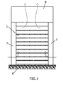
Figure 1 shows an upright view of the curtain arranged on the sector where the fire of the fire barrier device of this invention is located. -
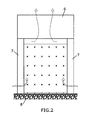
Figure 2 shows an upright view of the curtain arranged in a sector adjacent to the sector of the fire barrier device in this invention where the fire is located. -
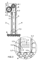
Figure 3 shows a lateral cross section view of the fire barrier device in this invention. -
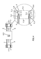
Figure 4 shows a cross section front view of the fire barrier device in this invention. - In the light of the aforementioned description, this invention refers to a fire barrier device which is provided with a first curtain (1) arranged in the sector (2) where the fire is located and a second curtain (3) arranged in a sector (4) adjacent to the sector (2) where the fire is located, where both curtains (1, 3), arranged in parallel are separated by an air chamber (5) 200 mm wide.
- The curtain (1) arranged in the sector (2) where the fire is located comprises rigid insulating material (1.1) for thermal insulation at high temperatures which is covered on both sides by fire proof fabric (1.2).
- This curtain (1) arranged in the sector (2) where the fire is formed by means of a series of layers which are provided in their interior with a fragment of rigid insulating material (1.1), in the external part of the fire proof material (1.2) and they are separated from each other in a vertical direction by respective galvanised plates (1.3), one on each side of the curtain (1) and which occupies the whole width thereof (1) and which are connected by means of rivets (1.4), plates(1.3) between which is arranged in turn in the interior of the fireproof fabric (1.2), a foam laminated joint (1.5).
- The curtain (3) arranged in the sector (4) adjacent to the sector (2) where the fire is located comprises a spongy insulating material (3.1) for thermal insulation at low temperatures which is covered on both sides by a fireproof fabric (3.2).
- This curtain (3) arranged in the sector (4) adjacent to the sector (2) where the fire is located is provided with a series of rivets (3.3) regularly arranged on the surface of the curtain (2) which serve to make it rigid.
- Both the curtain (1) arranged in the sector (2) where the fire is located and the curtain (3) arranged in the sector (4) adjacent to the sector (2) where the fire is located are rolled round respective axes (6.1) arranged in a blind casing (6) arranged over both (1, 3).
- In the lower part of both curtains (1, 3) angular profiles are arranged (1.7, 3.5) which ensure that each of the curtains (1, 3) are tight with the floor(8).
- In the sides of both curtains (1, 3) "L" shaped attachment parts (1.6, 3.4) are arranged which are antagonistic to the free ends (7.1) of lateral guide casings (7) which form the frame of the device, preventing their exit and maintaining the stability of each curtain within the guides (7.2) present in said lateral guide casings (7), when pressure is increased due to the high temperatures deriving from fire.
- Air enters from the outside to the air chamber (5) through lower entrances (7.3) arranged on the lateral guide casings (7)and an upper outlet (6.2)in the blind casing (6) where the hot air exits to the outside.
- In the interior of the lateral guide casings (7) a sealed internal duct is arranged (not shown) which permits pressures to be controlled inside the air chamber (5) and air to be supplied to the interior of said chamber (5) separating both curtains (1, 3).
- Movement of air through the interior of the air chamber (5) is at a constant speed which ensures that heat is dissipated in a way which produces a reduction in the temperature of 350°C of the face in contact with the fire to the face in contact with the air chamber (5) of the curtain (1) arranged in the sector (2) where the fire is located, thus ensuring temperatures which do not exceed 150°C more than the ambient temperature on the face of the curtain (3) arranged in the sector (4) adjacent to the sector (2) where the fire is located.
- In this example of a preferred embodiment, the device is 10 m wide and is separated from other adjacent devices which cover an enclosure by means of metal pillars (not shown).
- The essential nature of this invention is not altered by variations in materials, form, size and arrangement of the component elements, described in a manner which is not restrictive but which is sufficient for it to be reproduced by an expert.
Claims (15)
- a.― Fire barrier device characterised in that it is provide with a first curtain (1) arranged in the sector (2) where the fire is located and a second curtain (3) arranged in a sector (4) adjacent to the sector (2) where the fire is located, and where both curtains (1 3) are separated by an air chamber (3) which thermally insulates the side of the second curtain (3) arranged in the sector (4) adjacent to the sector (2) where the fire is located.
- a.― Fire barrier device according to claim 1 characterised in that the air chamber (5) is provided with at least one entrance(7.3) through which air enters from outside and an outlet (6.2) through which hot air exits due to contact of the first curtain (1) with the sector (2) in which the fire is located, which cools the device and, as a result, the second curtain (3).
- a.― Fire barrier device according to claim 2 characterised in that the temperature on the curtain face (3) arranged on the side of the sector (4) adjacent to the sector (2) where the fire is located does not exceed 150°C over the ambient temperature.
- a.― Fire barrier device according to claim 2 characterised in that the air enters from outside the air chamber (5) through lower entrances (7.3) and it exits the chamber (5) through an upper outlet (6.2).
- a.― Fire barrier device according to claim 1 characterised in that the curtain (1)arranged in the sector (2) where the fire is located comprises a rigid insulating material (1.1) for thermal insulation at high temperatures which is covered on both sides by a fire proof fabric (1.2).
- a.― Fire barrier device according to claim 5 characterised in that this curtain (1) arranged in the sector (2) where the fire is located is formed by a series of layers which are provided in their interior with a fragment of rigid insulating material (1.1) and in their external fireproof part (1.2) they are separated from each other in a vertical direction by respective galvanised plates (1.3), one on each side of the curtain (1) and they occupy the whole width of the same (1) and are connected by means of rivets (1.4), plates (1.3) between which in turn in the interior of the fireproof fabric (1.2) a foam laminated joint (1.5) is arranged.
- a.― Fire barrier device according to claim 1 characterised in that the curtain (3) arranged in the sector (4) adjacent to the sector (2) where the fire is located comprises spongy insulating material (3.1) for thermal insulation at low temperatures which are covered on both sides by a fireproof fabric (3.2).
- a.― Fire barrier device according to claim 7 characterised in that the curtain (3) arranged in the sector (4) adjacent to the sector (2) where the fire is located is provided with a series of rivets (3.3) which are regularly arranged on the surface of the curtain (2) which serve to stiffen the same.
- a.― Fire barrier device according to claim 1 characterised in that both the curtain (1) arranged in the sector (2) where the fire is located and the curtain (3) arranged in the sector (4) adjacent to the sector (2) where the fire is located are rolled round respective axes (6.1) arranged in a blind casing (6) arranged over both (1, 3).
- a.― Fire barrier device according to claim 1 characterised in that in the lower part of both curtains (1, 3) angular profiles are arranged (1.7, 3.5) which ensure tightness of each curtain (1, 3) with the floor (8).
- a.― Fire barrier device according to claim 7 characterised in that on the sides of both curtains (1, 3)L-shaped attachment parts are arranged (1.6, 3.4) which are antagonistic to the free ends (7.1) of lateral guide casings (7) which form the frame of the device, preventing their exit and maintaining the stability of each curtain within the guides (7.2) present in said lateral guide casings (7) when the pressure is increased due to high temperatures deriving from fire.
- a.― Fire barrier device according to claims 4 and 11 characterised in that the air enters from outside through lower entrances (7.3) arranged in the lateral guide casings (7) and an upper outlet (6.2) present in the blind casing (6) where the hot air exits to the outside.
- a.― Fire barrier device according to claim 11 characterised in that inside the lateral guide casings (7) a sealed interior duct is arranged which permits control of the pressures in the air chamber (5) interior and the supply of air to the interior of said chamber (5) separating both curtains (1, 3).
- a.― Fire barrier device according to claim 3 characterised in that the movement of air through the interior of the air chamber (5) is carried out at a constant speed.
- a.― Fire barrier device according to any of the claims characterised in that it has a width of 10 m and is separated from other adjacent devices which cover an enclosure by means of metal pillars and the width of the air chamber (5) are 200 mm.
Priority Applications (1)
| Application Number | Priority Date | Filing Date | Title |
|---|---|---|---|
| EP10382107A EP2384792A1 (en) | 2010-05-04 | 2010-05-04 | Fire barrier device |
Applications Claiming Priority (1)
| Application Number | Priority Date | Filing Date | Title |
|---|---|---|---|
| EP10382107A EP2384792A1 (en) | 2010-05-04 | 2010-05-04 | Fire barrier device |
Publications (1)
| Publication Number | Publication Date |
|---|---|
| EP2384792A1 true EP2384792A1 (en) | 2011-11-09 |
Family
ID=42751886
Family Applications (1)
| Application Number | Title | Priority Date | Filing Date |
|---|---|---|---|
| EP10382107A Withdrawn EP2384792A1 (en) | 2010-05-04 | 2010-05-04 | Fire barrier device |
Country Status (1)
| Country | Link |
|---|---|
| EP (1) | EP2384792A1 (en) |
Cited By (6)
| Publication number | Priority date | Publication date | Assignee | Title |
|---|---|---|---|---|
| CN104060937A (en) * | 2014-06-30 | 2014-09-24 | 田聪 | Fireproof roller blind |
| ES2548068A1 (en) * | 2015-07-03 | 2015-10-13 | Universitat Politècnica De València | Barrier curtain against light, noise, heat, fire and electromagnetic radiation |
| EP3225283A1 (en) | 2016-03-29 | 2017-10-04 | FIMARC Zenon Malkowski | Fireproof closure |
| CN108194001A (en) * | 2018-01-05 | 2018-06-22 | 安徽清启系统集成有限公司 | Fire curtain for rail train |
| CN109898967A (en) * | 2019-02-25 | 2019-06-18 | 徐金刚 | A kind of unmanned auto-control fire prevention fire-fighting isolating door |
| CN111911058A (en) * | 2019-05-08 | 2020-11-10 | 关魁魁 | Automatic trigger fire extinguishing type fireproof door |
Citations (4)
| Publication number | Priority date | Publication date | Assignee | Title |
|---|---|---|---|---|
| GB191023143A (en) * | 1910-10-06 | 1911-02-09 | James Godfrey Wilson | Improvements in Fireproof Structures. |
| US3955323A (en) * | 1975-06-04 | 1976-05-11 | Canadian Patents And Development Limited | Means for retarding the spread of fire from a building space |
| EP1559449A1 (en) * | 2004-01-27 | 2005-08-03 | Goldfire Sprl | Flexible wall having fire resistant properties |
| US20060150533A1 (en) * | 2004-12-27 | 2006-07-13 | Yu-Chang Lin | Double-layer fireproof curtain apparatus |
-
2010
- 2010-05-04 EP EP10382107A patent/EP2384792A1/en not_active Withdrawn
Patent Citations (4)
| Publication number | Priority date | Publication date | Assignee | Title |
|---|---|---|---|---|
| GB191023143A (en) * | 1910-10-06 | 1911-02-09 | James Godfrey Wilson | Improvements in Fireproof Structures. |
| US3955323A (en) * | 1975-06-04 | 1976-05-11 | Canadian Patents And Development Limited | Means for retarding the spread of fire from a building space |
| EP1559449A1 (en) * | 2004-01-27 | 2005-08-03 | Goldfire Sprl | Flexible wall having fire resistant properties |
| US20060150533A1 (en) * | 2004-12-27 | 2006-07-13 | Yu-Chang Lin | Double-layer fireproof curtain apparatus |
Cited By (11)
| Publication number | Priority date | Publication date | Assignee | Title |
|---|---|---|---|---|
| CN104060937A (en) * | 2014-06-30 | 2014-09-24 | 田聪 | Fireproof roller blind |
| ES2548068A1 (en) * | 2015-07-03 | 2015-10-13 | Universitat Politècnica De València | Barrier curtain against light, noise, heat, fire and electromagnetic radiation |
| WO2017005948A1 (en) * | 2015-07-03 | 2017-01-12 | Universitat Politècnica De Valencia | Curtain providing a barrier against light, noise, heat, fire and electromagnetic radiation |
| US10867592B2 (en) | 2015-07-03 | 2020-12-15 | Universitat Politecnica De Valencia | Curtain providing a barrier against light, noise, heat, fire and electromagnetic radiation |
| EP3225283A1 (en) | 2016-03-29 | 2017-10-04 | FIMARC Zenon Malkowski | Fireproof closure |
| EP3679987A1 (en) | 2016-03-29 | 2020-07-15 | FIMARC Zenon Malkowski | Fire protection closure |
| CN108194001A (en) * | 2018-01-05 | 2018-06-22 | 安徽清启系统集成有限公司 | Fire curtain for rail train |
| CN109898967A (en) * | 2019-02-25 | 2019-06-18 | 徐金刚 | A kind of unmanned auto-control fire prevention fire-fighting isolating door |
| CN109898967B (en) * | 2019-02-25 | 2021-02-05 | 涡阳县幸福门业有限公司 | An unmanned automatic fire and fire isolation door |
| CN111911058A (en) * | 2019-05-08 | 2020-11-10 | 关魁魁 | Automatic trigger fire extinguishing type fireproof door |
| CN111911058B (en) * | 2019-05-08 | 2022-08-12 | 安徽通晓防火门有限公司 | An automatic trigger fire extinguishing type fire door |
Similar Documents
| Publication | Publication Date | Title |
|---|---|---|
| EP2384792A1 (en) | Fire barrier device | |
| EP0198858B1 (en) | Fireproof cabinet system for electronic equipment | |
| WO2014104580A1 (en) | Evacuation device | |
| CN102946949B (en) | Fire prevention-or smoke control device | |
| EP3542870B1 (en) | A ventilation system for a building having a smoke evacuation functionality and a method for operating said system | |
| US10375843B2 (en) | Switchgear exhaust assembly | |
| KR102664728B1 (en) | Structure of window frame for supporting fireproof glass windows | |
| KR100803315B1 (en) | High-rise building ventilation system with radiant heat shield | |
| US7331401B2 (en) | Method and apparatus for fighting a fire in an enclosed space in an aircraft | |
| JP2003111858A (en) | Fire and smoke compartment formation system | |
| US20070039744A1 (en) | Tunnel fire protection system | |
| JP6636763B2 (en) | curtain wall | |
| JP6431416B2 (en) | Fall-off prevention device and fall-off prevention method for fireproof caps installed in the fire-prevention compartment penetration of the refrigerant piping system | |
| TWM496677U (en) | Improved curtain airtight structure of rolling curtain box for fireproof rolling door | |
| CN112918303A (en) | Fireproof electric automobile charging pile and intelligent fireproof charging station | |
| ES2832703T3 (en) | Fire protection enclosure | |
| JPH09268852A (en) | Architectural thermal shutter | |
| KR102212160B1 (en) | Fire Shutter for Vessel | |
| KR20110010737U (en) | Fire protection heat shield | |
| KR102240543B1 (en) | toxic gas defence system for hospital fire using sickroom | |
| JP2026007951A (en) | Building heat insulation structure | |
| KR100859526B1 (en) | Horizontal movable folding shutter | |
| KR20240109730A (en) | Sliding window for fire prevention | |
| CN114945413B (en) | Disaster prevention device and disaster prevention equipment | |
| ITMO20110097A1 (en) | PANEL FOR SOLAR ENERGY CONVERSION. |
Legal Events
| Date | Code | Title | Description |
|---|---|---|---|
| AK | Designated contracting states |
Kind code of ref document: A1 Designated state(s): AL AT BE BG CH CY CZ DE DK EE ES FI FR GB GR HR HU IE IS IT LI LT LU LV MC MK MT NL NO PL PT RO SE SI SK SM TR |
|
| AX | Request for extension of the european patent |
Extension state: BA ME RS |
|
| PUAI | Public reference made under article 153(3) epc to a published international application that has entered the european phase |
Free format text: ORIGINAL CODE: 0009012 |
|
| 17P | Request for examination filed |
Effective date: 20120327 |
|
| STAA | Information on the status of an ep patent application or granted ep patent |
Free format text: STATUS: THE APPLICATION IS DEEMED TO BE WITHDRAWN |
|
| 18D | Application deemed to be withdrawn |
Effective date: 20131203 |