EP2384676B1 - Kitchen appliance suitable for being locked with a safety device - Google Patents
Kitchen appliance suitable for being locked with a safety device Download PDFInfo
- Publication number
- EP2384676B1 EP2384676B1 EP20110305539 EP11305539A EP2384676B1 EP 2384676 B1 EP2384676 B1 EP 2384676B1 EP 20110305539 EP20110305539 EP 20110305539 EP 11305539 A EP11305539 A EP 11305539A EP 2384676 B1 EP2384676 B1 EP 2384676B1
- Authority
- EP
- European Patent Office
- Prior art keywords
- cup
- motorised
- box
- household electrical
- food preparation
- Prior art date
- Legal status (The legal status is an assumption and is not a legal conclusion. Google has not performed a legal analysis and makes no representation as to the accuracy of the status listed.)
- Not-in-force
Links
Images


Classifications
-
- A—HUMAN NECESSITIES
- A47—FURNITURE; DOMESTIC ARTICLES OR APPLIANCES; COFFEE MILLS; SPICE MILLS; SUCTION CLEANERS IN GENERAL
- A47J—KITCHEN EQUIPMENT; COFFEE MILLS; SPICE MILLS; APPARATUS FOR MAKING BEVERAGES
- A47J43/00—Implements for preparing or holding food, not provided for in other groups of this subclass
- A47J43/04—Machines for domestic use not covered elsewhere, e.g. for grinding, mixing, stirring, kneading, emulsifying, whipping or beating foodstuffs, e.g. power-driven
- A47J43/07—Parts or details, e.g. mixing tools, whipping tools
- A47J43/075—Safety devices
- A47J43/0755—Safety devices for machines with tools driven from the upper side
Definitions
- the present invention relates to the technical field of electrical household appliances for culinary preparation comprising a rotary working tool arranged in a working container and an upper motorized housing mounted on the working container.
- the present invention more particularly relates to apparatus of the aforementioned type in which the upper motorized housing is locked on the working container and comprises a safety device provided for detecting the presence of the working container and a cup interposed between the upper motor housing and the working container.
- the document WO 98/24350 discloses an apparatus comprising a motorized upper case locked on a cup by means of a moving part moved by a control button, the cup having a shutter wall locked by bayonet on the working container by means of another moving part .
- An object of the present invention is to provide a food preparation apparatus comprising a motorized upper case locked on a working container and a safety device, which has a simplified construction.
- Another object of the present invention is to provide a food preparation apparatus comprising a motorized upper case locked on a working container and a safety device, which has a facilitated use.
- a household appliance preparation a motorized upper motor housing arranged on a working receptacle housing a cup, the upper motorized housing carrying a movable safety element between a rest position which does not allow the operation of the apparatus and an active position allowing the operation of the the apparatus, since the cup in place under the upper motor housing pushes the safety element to an intermediate position which does not allow the operation of the apparatus, that the upper motor housing is rotatably locked to the container of the workpiece carrying the cup, and that the working container has a cam surface adapted to push the safety element from the intermediate position to the active position during locking by rotation of the upper motor housing on the working container carrying the cup.
- the security element directly detects the presence of the working container and the cup.
- the movement of the safety element from the rest position to the active position comprises a first part made by the cup, making it possible to reach an intermediate position of the safety element, and a second part made by the working container. , from the intermediate position of the security element.
- the cam surface of the working container allows different directions to be used for the positioning movement of the cup and for the locking movement of the working container with the upper motor housing.
- the device has both a simple and safe use.
- the upper motorized housing is bayonet-locked on the working container. This arrangement makes it possible to limit the rotation of the upper motor housing relative to the working receptacle in order to lock the apparatus.
- the upper motorized housing could in particular be screwed on the working container.
- the working receptacle comprises locking members extending inside said working receptacle. This arrangement reduces the size of the device, the lower part of the upper motorized housing can be inserted into the working container.
- the security element comprises a detection member mounted in an opening of a lower wall of the upper motor housing and the cup in place under the upper motorized housing pushes the detection member towards the inside of the upper motor housing.
- the upper motorized housing can simply be placed on the cup in place in the working container, to bring the security element to the intermediate position.
- the detection member is prominent inside a cavity of said bottom wall when the security element occupies the rest position. This arrangement makes it more difficult for the user to actuate the detection member.
- the cup has an upper face having an annular detection zone arranged opposite the detection member, said annular detection zone having a geometry of revolution.
- This arrangement allows to set up the cup in the working container, without particular orientation. The use of the apparatus is thus facilitated.
- the annular detection zone is formed by an annular upper rib of the cup. This arrangement reduces the size of the security element.
- the cam surface is formed by a beveled control member having a lower surface adapted to cooperate with a bearing surface of the upper motor housing and an upper surface provided to push the safety element towards the active position when rotating the working container relative to the upper motor housing to lock the upper motor housing on the working container carrying the cup.
- the lower surface of the control member thus makes it possible to lock the upper motorized housing on the working receptacle, the upper surface of the control member moving the safety element towards the active operating position of the apparatus.
- the surface lower and / or the upper surface may be inclined relative to the plane of rotation of the upper motor housing on the working container.
- the security element has a blocking member hindering the stroke of the control member when locking the upper motor housing on the working container in the absence of the cup.
- This arrangement avoids locking the upper motor housing on the working container in the absence of the cup. The user trying to lock the device to make it work is thus informed that the device is not used in a compliant configuration.
- the security element could have a locking member hindering the stroke of another part of the working container.
- the working container has an internal annular support zone intended to receive the cup. This arrangement ensures a relative seal between the working container and the cup at said annular support zone.
- the upper motorized housing comprises a switch controlling the operation of the apparatus and a movable control button between a stop position in which the switch does not allow the operation of the apparatus and a position in operation. which switch allows operation of the apparatus when the security element is in the active position.
- the switch is mounted on a mobile support that can be moved by the control button between a raised position in which the switch does not allow the operation of the device and a lowered position in which the switch allows operation of the device when the security element is in the active position.
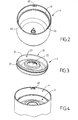
- the appliance for cooking preparation illustrated on the Figures 1 to 13 has a motorized upper case 1, a cup 2, a working tool rotating 3 and a working container 4.
- the upper motor housing 1 is disposed on the working container 4.
- the working container 4 carries the upper motor housing 1.
- the upper motorized housing 1 houses a motor 10 (visible on the figure 5 ) for driving the rotary working tool 3 arranged in the working receptacle 4.
- the motor 10 is connected to a driving member 11 arranged on the lower side of the upper motor housing 1.
- the upper motor housing 1 is locked by rotation on the working receptacle 4 carrying the cup 2.
- the working receptacle 4 comprises locking members 40 provided to cooperate with retaining members 12 belonging to the upper motor housing 1.
- the upper motorized housing 1 is bayonet-locked on the working receptacle 4. As visible on the figure 2 the working receptacle 4 has three locking members 40; the upper motorized housing 1 comprises three retaining members 12 provided for retaining the locking members 40.
- the upper motorized housing 1 has a lower portion 13 adapted to be inserted into the working receptacle 4.
- the locking members 40 extend inside the working receptacle 4.
- the retaining members 12 are arranged in the outside of the lower portion 13 of the upper motor housing 1.
- the lower portion 13 has three inverted lateral cutouts L 14 housing the retaining members 12, the lateral indentations 14 being provided to receive the locking members 40 .
- the working container 4 houses the cup 2.
- the working receptacle 4 has an internal annular support zone 41 designed to receive the cup 2.
- the cup 2 is arranged in the working container 4.
- the cup 2 rests on the internal annular support zone 41.
- cup 2 has a peripheral edge 20 provided to rest on the inner annular support zone 41.
- the peripheral edge 20 is arranged on an annular upper rib 21 of the cup 2.
- the cup 2 has a central opening 22 provided for the passage of the part upper part of the rotary working tool 3.
- the working container 4 houses the rotary working tool 3.
- the upper motorized housing 1 comprises a main body 15, mounted on the lower part 13, the main body 15 being visible on the figure 1 but not being represented on the figure 5 .
- the upper motor housing 1 comprises a switch 50 controlling the operation of the apparatus.
- the upper motorized box 1 comprises a control button 51, visible on the figure 5 .
- the control button 51 is carried by the main body 15.
- the control button 51 is mounted to move against an elastic return member 52.
- the resilient return member 52 rests for example on the motor 10.
- the control button 51 is capable of displacing a movable support 53 carrying the switch 50.
- the movable support 53 is movably mounted against resilient return means 54.
- the elastic return means 54 rest for example on the lower part 13.
- the upper motorized housing 1 carries a movable security element 60 between a rest position which does not allow the operation of the apparatus, illustrated in FIG. figure 11 , and an active position allowing the operation of the apparatus, illustrated on the figure 13 .
- the cup 2 in place under the upper motorized housing 1 pushes the security element 60 to an intermediate position that does not allow the operation of the device.
- the intermediate position of the security element 60 is illustrated on the figure 12 .
- the control button 51 is movable between a stop position in which the switch 50 does not allow the operation of the apparatus and an on position in which the switch 50 allows the operation of the apparatus when the security element 60 is in the active position.
- the switch 50 is mounted on the movable support 53 that can be moved by the control button 51 between a position raised in which the switch 50 does not allow the operation of the apparatus and a lowered position in which the switch 50 allows the operation of the apparatus when the security element 60 occupies the active position.
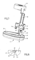
- the security element 60 comprises a detection member 61 designed to cooperate with the cup 2. As visible on the figure 6 , the detection member 61 is mounted in an opening 16 of a lower wall 17 of the upper motorized housing 1. The detection member 61 is prominent inside a cavity 19 of said lower wall 17 when the safety element 60 occupies the rest position. The cup 2 in place under the upper motorized casing 1 pushes the detection member 61 towards the inside of the upper motorized casing 1.
- the cup 2 has an upper face 23 visible on the figure 3 .
- the upper face 23 of the cup 2 comprises an annular detection zone 24 arranged facing the detection member 61, when the cup 2 is in place under the security element 60, as shown in FIG. figure 7 .
- the annular detection zone 24 has a geometry of revolution, allowing placement of the cup 2 under the upper motorized casing 1 without particular angular indexing. More particularly, the annular detection zone 24 is formed by the annular upper rib 21 of the cup 2.
- the cavity 19 is formed by an annular groove.
- the working receptacle 4 has a cam surface 42 adapted to push the safety element 60 from the intermediate position to the active position when the motorized upper housing 1 is locked by rotation on the working receptacle 4 carrying the cup 2. that visible on the figure 8 the cam surface 42 is formed by a beveled control member 43 having a lower surface 44 and an upper surface 45.
- the lower surface 44 is provided to cooperate with a bearing surface 18 of the upper motorized housing 1. More particularly, the control member 43 corresponds to one of the locking members 40, and the bearing surface 18 corresponds to the retaining member 12 adjacent to the element security 60.
- the upper surface 45 is provided to push the safety element 60 towards the active position during the rotation of the working receptacle 4 relative to the upper motor housing 1 to lock the upper motor housing 1 on the working receptacle 4 carrying the cup 2.
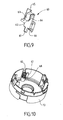
- the upper surface 45 pushes a second detecting member 62 of the security element 60. More particularly, the second detecting member 62 is formed by the lower end of a tab 63 arranged in one of the lateral indentations. 14 of the lower part 13 of the upper motor housing 1.
- the safety element 60 has a blocking member 64 which prevents the stroke of the control member 43 when the upper motorized housing 1 is locked on the working receptacle 4 in the absence of the cup 2, when the security 60 occupies the rest position. More particularly, the blocking member 64 is formed by a lateral face of the tongue 63 arranged in one of the lateral indentations 14 of the lower part 13 of the upper motorized box 1.Tel visible on the figure 12 , the locking member 64 occupies the bottom of the notch 14 beyond the bearing surface 18.
- the security element 60 has an upper actuating surface 65.
- the actuating surface 65 is provided to actuate an actuating button 55 of the switch 50, as visible on the figure 7 .
- the security element 60 has a guiding member 66 provided for translational movement of the safety element 60 relative to the upper motorized housing 1.
- the security element 60 is movably mounted against an elastic return device 67 comprising a helical spring held by a screw 68.
- the apparatus according to the invention is used and operates in the following manner.
- the user sets up the cup 2 in the working receptacle 4, then arranges the upper motor housing 1 on the working receptacle 4 in introducing the locking members 40 of the working receptacle 4 into the lateral indentations 14 of the upper motor housing 1.
- the annular upper rib 21 of the cup 2 pushes the detecting member 61 of the safety element 60.
- safety 60 is then moved from the rest position illustrated on the figure 11 at the intermediate position shown on the figure 12 .
- the locking member 40 forming the cam surface 42 can then be inserted under the second detecting member 62 of the security element 60.
- the user can thus turn the upper motorized housing 1 relative to the working receptacle 4.
- the locking members 40 engaged in the lateral indentations 14 bear on the retaining members 12 and lock the upper motor housing 1 on the working receptacle 4.
- the cam surface 42 bearing on the bearing surface 18 of the motorized housing upper 1 raises the second detection member 62 of the security element 60.
- the security element 60 is then moved from the intermediate position illustrated on the figure 12 at the active position shown on the figure 13 .
- the apparatus can then operate if the user presses the control button 51.
- the displacement of the movable support 53 carrying the switch 50 towards the on position brings the operation button 55 of the switch 50 into contact with the surface actuating device 65 of the security element 60 in the active position.
- the proposed apparatus thus presents an easy use and a relatively simple construction.
- the use of the cup 2 to perform the first part of the movement of the security element 60 and the working container 4 to achieve the second part of the movement of the security element 60 makes the apparatus particularly safe.
- the rotary working tool 3 is not necessarily mounted on the bottom of the working container 4, but could in particular be suspended mounted under the upper motorized housing 1.
- control member 43 could be distinct from the locking members 40.
- the upper motorized housing 1 could be devoid of control button 51, the switch 50 being arranged in the upper motor housing 1 in a position corresponding to the aforementioned operating position, the locking of the motorized upper housing 1 on the working container 4 carrying the cup 2 then bringing the actuating surface 65 of the safety element 60 into the active position in contact with the actuating button 55 of the switch 50.
- the upper motorized housing 1 could be locked by screwing on the working receptacle 4.
Landscapes
- Engineering & Computer Science (AREA)
- Mechanical Engineering (AREA)
- Food Science & Technology (AREA)
- Food-Manufacturing Devices (AREA)
- Cookers (AREA)
Description
La présente invention concerne le domaine technique des appareils électroménagers de préparation culinaire comportant un outil de travail rotatif agencé dans un récipient de travail et un boîtier motorisé supérieur monté sur le récipient de travail.The present invention relates to the technical field of electrical household appliances for culinary preparation comprising a rotary working tool arranged in a working container and an upper motorized housing mounted on the working container.
La présente invention concerne plus particulièrement les appareils du type précité dans lesquels le boîtier motorisé supérieur est verrouillé sur le récipient de travail et comporte un dispositif de sécurité prévu pour détecter la présence du récipient de travail et d'une coupelle interposée entre le boîtier motorisé supérieur et le récipient de travail.The present invention more particularly relates to apparatus of the aforementioned type in which the upper motorized housing is locked on the working container and comprises a safety device provided for detecting the presence of the working container and a cup interposed between the upper motor housing and the working container.
Le document
Un objet de la présente invention est de proposer un appareil de préparation culinaire comportant un boîtier motorisé supérieur verrouillé sur un récipient de travail et un dispositif de sécurité, qui présente une construction simplifiée.An object of the present invention is to provide a food preparation apparatus comprising a motorized upper case locked on a working container and a safety device, which has a simplified construction.
Un autre objet de la présente invention est de proposer un appareil de préparation culinaire comportant un boîtier motorisé supérieur verrouillé sur un récipient de travail et un dispositif de sécurité, qui présente une utilisation facilitée.Another object of the present invention is to provide a food preparation apparatus comprising a motorized upper case locked on a working container and a safety device, which has a facilitated use.
Ces objets sont atteints avec un appareil électroménager de préparation culinaire, comportant un boîtier motorisé supérieur disposé sur un récipient de travail logeant une coupelle, le boîtier motorisé supérieur portant un élément de sécurité mobile entre une position de repos n'autorisant pas le fonctionnement de l'appareil et une position active autorisant le fonctionnement de l'appareil, du fait que la coupelle en place sous le boîtier motorisé supérieur repousse l'élément de sécurité vers une position intermédiaire n'autorisant pas le fonctionnement de l'appareil, que le boîtier motorisé supérieur est verrouillé par rotation sur le récipient de travail portant la coupelle, et que le récipient de travail présente une surface de came apte à repousser l'élément de sécurité de la position intermédiaire vers la position active lors du verrouillage par rotation du boîtier motorisé supérieur sur le récipient de travail portant la coupelle. Ainsi l'élément de sécurité détecte directement la présence du récipient de travail et de la coupelle. Le déplacement de l'élément de sécurité de la position de repos à la position active comporte une première partie effectuée par la coupelle, permettant d'atteindre une position intermédiaire de l'élément de sécurité, et une deuxième partie effectuée par le récipient de travail, à partir de la position intermédiaire de l'élément de sécurité. La surface de came du récipient de travail permet d'utiliser des directions différentes pour le mouvement de mise en place de la coupelle et pour le mouvement de verrouillage du récipient de travail avec le boîtier motorisé supérieur. L'appareil présente à la fois une utilisation simple et sûre.These objects are achieved with a household appliance preparation a motorized upper motor housing arranged on a working receptacle housing a cup, the upper motorized housing carrying a movable safety element between a rest position which does not allow the operation of the apparatus and an active position allowing the operation of the the apparatus, since the cup in place under the upper motor housing pushes the safety element to an intermediate position which does not allow the operation of the apparatus, that the upper motor housing is rotatably locked to the container of the workpiece carrying the cup, and that the working container has a cam surface adapted to push the safety element from the intermediate position to the active position during locking by rotation of the upper motor housing on the working container carrying the cup. Thus the security element directly detects the presence of the working container and the cup. The movement of the safety element from the rest position to the active position comprises a first part made by the cup, making it possible to reach an intermediate position of the safety element, and a second part made by the working container. , from the intermediate position of the security element. The cam surface of the working container allows different directions to be used for the positioning movement of the cup and for the locking movement of the working container with the upper motor housing. The device has both a simple and safe use.
Selon un mode de réalisation avantageux, le boîtier motorisé supérieur est verrouillé par baïonnette sur le récipient de travail. Cette disposition permet de limiter la rotation du boîtier motorisé supérieur par rapport au récipient de travail pour réaliser le verrouillage de l'appareil. En alternative, le boîtier motorisé supérieur pourrait notamment être vissé sur le récipient de travail.According to an advantageous embodiment, the upper motorized housing is bayonet-locked on the working container. This arrangement makes it possible to limit the rotation of the upper motor housing relative to the working receptacle in order to lock the apparatus. Alternatively, the upper motorized housing could in particular be screwed on the working container.
Avantageusement, le récipient de travail comporte des organes de verrouillage s'étendant à l'intérieur dudit récipient de travail. Cette disposition permet de réduire l'encombrement de l'appareil, la partie inférieure du boîtier motorisé supérieur pouvant être insérée dans le récipient de travail.Advantageously, the working receptacle comprises locking members extending inside said working receptacle. This arrangement reduces the size of the device, the lower part of the upper motorized housing can be inserted into the working container.
Avantageusement, l'élément de sécurité comporte un organe de détection monté dans une ouverture d'une paroi inférieure du boîtier motorisé supérieur et la coupelle en place sous le boîtier motorisé supérieur repousse l'organe de détection vers l'intérieur du boîtier motorisé supérieur. Ainsi le boîtier motorisé supérieur peut être simplement posé sur la coupelle en place dans le récipient de travail, pour amener l'élément de sécurité en position intermédiaire.Advantageously, the security element comprises a detection member mounted in an opening of a lower wall of the upper motor housing and the cup in place under the upper motorized housing pushes the detection member towards the inside of the upper motor housing. Thus the upper motorized housing can simply be placed on the cup in place in the working container, to bring the security element to the intermediate position.
Avantageusement alors, l'organe de détection est proéminent à l'intérieur d'une cavité de ladite paroi inférieure lorsque l'élément de sécurité occupe la position de repos. Cette disposition permet de rendre plus difficile l'actionnement de l'organe de détection par l'utilisateur.Advantageously then, the detection member is prominent inside a cavity of said bottom wall when the security element occupies the rest position. This arrangement makes it more difficult for the user to actuate the detection member.
Avantageusement alors, la coupelle présente une face supérieure comportant une zone annulaire de détection agencée en regard de l'organe de détection, ladite zone annulaire de détection présentant une géométrie de révolution. Cette disposition permet de mettre en place la coupelle dans le récipient de travail, sans orientation particulière. L'utilisation de l'appareil est ainsi facilitée.Advantageously then, the cup has an upper face having an annular detection zone arranged opposite the detection member, said annular detection zone having a geometry of revolution. This arrangement allows to set up the cup in the working container, without particular orientation. The use of the apparatus is thus facilitated.
Avantageusement alors, la zone annulaire de détection est formée par une nervure supérieure annulaire de la coupelle. Cette disposition permet de réduire la taille de l'élément de sécurité.Advantageously then, the annular detection zone is formed by an annular upper rib of the cup. This arrangement reduces the size of the security element.
Avantageusement encore, la surface de came est formée par un organe de commande en biseau présentant une surface inférieure prévue pour coopérer avec une surface d'appui du boîtier motorisé supérieur et une surface supérieure prévue pour repousser l'élément de sécurité vers la position active lors de la rotation du récipient de travail par rapport au boîtier motorisé supérieur pour verrouiller le boîtier motorisé supérieur sur le récipient de travail portant la coupelle. La surface inférieure de l'organe de commande permet ainsi de verrouiller le boîtier motorisé supérieur sur le récipient de travail, la surface supérieure de l'organe de commande déplaçant l'élément de sécurité vers la position active de fonctionnement de l'appareil. La surface inférieure et/ou la surface supérieure peuvent être inclinées par rapport au plan de rotation du boîtier motorisé supérieur sur le récipient de travail.Advantageously, the cam surface is formed by a beveled control member having a lower surface adapted to cooperate with a bearing surface of the upper motor housing and an upper surface provided to push the safety element towards the active position when rotating the working container relative to the upper motor housing to lock the upper motor housing on the working container carrying the cup. The lower surface of the control member thus makes it possible to lock the upper motorized housing on the working receptacle, the upper surface of the control member moving the safety element towards the active operating position of the apparatus. The surface lower and / or the upper surface may be inclined relative to the plane of rotation of the upper motor housing on the working container.
Avantageusement alors, l'élément de sécurité présente un organe de blocage entravant la course de l'organe de commande lors du verrouillage du boîtier motorisé supérieur sur le récipient de travail en l'absence de la coupelle. Cette disposition permet d'éviter le verrouillage du boîtier motorisé supérieur sur le récipient de travail en l'absence de la coupelle. L'utilisateur essayant de verrouiller l'appareil pour le faire fonctionner est ainsi informé que l'appareil n'est pas utilisé dans une configuration conforme. En alternative, l'élément de sécurité pourrait présenter un organe de blocage entravant la course d'une autre partie du récipient de travail.Advantageously then, the security element has a blocking member hindering the stroke of the control member when locking the upper motor housing on the working container in the absence of the cup. This arrangement avoids locking the upper motor housing on the working container in the absence of the cup. The user trying to lock the device to make it work is thus informed that the device is not used in a compliant configuration. Alternatively, the security element could have a locking member hindering the stroke of another part of the working container.
Avantageusement encore, le récipient de travail présente une zone d'appui annulaire interne prévue pour recevoir la coupelle. Cette disposition permet d'assurer une étanchéité relative entre le récipient de travail et la coupelle au niveau de ladite zone d'appui annulaire.Advantageously, the working container has an internal annular support zone intended to receive the cup. This arrangement ensures a relative seal between the working container and the cup at said annular support zone.
Selon une forme de réalisation, le boîtier motorisé supérieur comporte un interrupteur commandant le fonctionnement de l'appareil et un bouton de commande mobile entre une position arrêt dans laquelle l'interrupteur n'autorise pas le fonctionnement de l'appareil et une position marche dans laquelle l'interrupteur autorise le fonctionnement de l'appareil lorsque l'élément de sécurité occupe la position active.According to one embodiment, the upper motorized housing comprises a switch controlling the operation of the apparatus and a movable control button between a stop position in which the switch does not allow the operation of the apparatus and a position in operation. which switch allows operation of the apparatus when the security element is in the active position.
Avantageusement alors, l'interrupteur est monté sur un support mobile susceptible d'être déplacé par le bouton de commande entre une position relevée dans laquelle l'interrupteur n'autorise pas le fonctionnement de l'appareil et une position abaissée dans laquelle l'interrupteur autorise le fonctionnement de l'appareil lorsque l'élément de sécurité occupe la position active.Advantageously then, the switch is mounted on a mobile support that can be moved by the control button between a raised position in which the switch does not allow the operation of the device and a lowered position in which the switch allows operation of the device when the security element is in the active position.
L'invention sera mieux comprise à l'étude d'un exemple de réalisation, pris à titre nullement limitatif, illustré dans les figures annexées, dans lesquelles :
- la
figure 1 est une vue en perspective éclatée d'un exemple de réalisation d'un appareil électroménager de préparation culinaire selon l'invention, - la
figure 2 est une vue de dessus en perspective du récipient de travail de l'appareil illustré sur lafigure 1 . - la
figure 3 est une vue de dessus en perspective de la coupelle de l'appareil illustré sur lafigure 1 , - la
figure 4 est une vue latérale en perspective montrant la coupelle illustrée sur lafigure 3 en place dans le récipient illustré sur lafigure 2 , - la
figure 5 est une vue de côté en perspective de l'intérieur du boîtier motorisé supérieur de l'appareil illustré sur lafigure 1 , - la
figure 6 est une vue de dessous du boîtier motorisé supérieur de l'appareil illustré sur lafigure 1 , - la
figure 7 est une vue de côté en perspective du dispositif de sécurité et de la coupelle de l'appareil illustré sur lafigure 1 , - la
figure 8 est une vue partielle de côté en perspective de l'intérieur du récipient de travail illustré sur lesfigures 1 ,2 et 4 , - la
figure 9 est une vue de côté en perspective de l'élément de sécurité du dispositif de sécurité illustré sur lafigure 7 , - la
figure 10 est une vue de dessus en perspective du montage de l'élément de sécurité illustré sur lafigure 9 dans le boîtier motorisé supérieur de l'appareil illustré sur lafigure 1 , - la
figure 11 est une vue de côté du boîtier motorisé supérieur illustrant la position de repos de l'élément de sécurité en l'absence de la coupelle, - la
figure 12 est une vue de côté du boîtier motorisé supérieur illustrant la position intermédiaire de l'élément de sécurité lorsque la coupelle (non représentée) est en place sous le boîtier motorisé supérieur, - la
figure 13 est une vue de côté du boîtier motorisé supérieur illustrant la position active de l'élément de sécurité lorsque le boîtier motorisé supérieur est verrouillé sur le récipient de travail (non représenté) portant la coupelle (non représentée).
- the
figure 1 is an exploded perspective view of an exemplary embodiment of an electrical household appliance for culinary preparation according to the invention, - the
figure 2 is a perspective view from above of the working container of the apparatus shown in FIG.figure 1 . - the
figure 3 is a top view in perspective of the cup of the apparatus illustrated on thefigure 1 , - the
figure 4 is a perspective side view showing the cup illustrated on thefigure 3 in place in the container shown on thefigure 2 , - the
figure 5 is a perspective side view of the interior of the upper motorized housing of the apparatus shown in FIG.figure 1 , - the
figure 6 is a bottom view of the motorized upper case of the device shown on thefigure 1 , - the
figure 7 is a perspective side view of the safety device and the cup of the apparatus illustrated in thefigure 1 , - the
figure 8 is a partial perspective side view of the interior of the work container illustrated on thefigures 1 ,2 and 4 , - the
figure 9 is a perspective side view of the security element of the security device shown in FIG.figure 7 , - the
figure 10 is a perspective view from above of the mounting of the security element illustrated on thefigure 9 in the motorized upper case of the device shown on thefigure 1 , - the
figure 11 is a side view of the upper motor housing illustrating the rest position of the safety element in the absence of the cup, - the
figure 12 is a side view of the upper motor housing illustrating the intermediate position of the safety element when the cup (not shown) is in place under the upper motor housing, - the
figure 13 is a side view of the upper motor housing illustrating the active position of the safety element when the upper motor housing is locked to the working container (not shown) carrying the cup (not shown).
L'appareil électroménager de préparation culinaire illustré sur les
Le boîtier motorisé supérieur 1 est disposé sur le récipient de travail 4. Le récipient de travail 4 porte le boîtier motorisé supérieur 1.The
Le boîtier motorisé supérieur 1 loge un moteur 10 (visible sur la
Tel que représenté sur les figures, le boîtier motorisé supérieur 1 est verrouillé par baïonnette sur le récipient de travail 4. Tel que visible sur la
Plus particulièrement, le boîtier motorisé supérieur 1 présente une partie inférieure 13 prévue pour être insérée dans le récipient de travail 4. Les organes de verrouillage 40 s'étendent à l'intérieur du récipient de travail 4. Les organes de retenue 12 sont agencés à l'extérieur de la partie inférieure 13 du boîtier motorisé supérieur 1. A cet effet, la partie inférieure 13 présente trois échancrures latérales 14 en L inversé logeant les organes de retenue 12, les échancrures latérales 14 étant prévues pour recevoir les organes de verrouillage 40.More particularly, the upper
Le récipient de travail 4 loge la coupelle 2. Tel que visible sur la
Le boîtier motorisé supérieur 1 comporte un corps principal 15, monté sur la partie inférieure 13, le corps principal 15 étant visible sur la
Le boîtier motorisé supérieur 1 porte un élément de sécurité 60 mobile entre une position de repos n'autorisant pas le fonctionnement de l'appareil, illustrée sur la
Le bouton de commande 51 est mobile entre une position arrêt dans laquelle l'interrupteur 50 n'autorise pas le fonctionnement de l'appareil et une position marche dans laquelle l'interrupteur 50 autorise le fonctionnement de l'appareil lorsque l'élément de sécurité 60 occupe la position active.The
L'interrupteur 50 est monté sur le support mobile 53 susceptible d'être déplacé par le bouton de commande 51 entre une position relevée dans laquelle l'interrupteur 50 n'autorise pas le fonctionnement de l'appareil et une position abaissée dans laquelle l'interrupteur 50 autorise le fonctionnement de l'appareil lorsque l'élément de sécurité 60 occupe la position active.The
L'élément de sécurité 60 comporte un organe de détection 61 prévu pour coopérer avec la coupelle 2. Tel que visible sur la
La coupelle 2 présente une face supérieure 23 visible sur la
Le récipient de travail 4 présente une surface de came 42 apte à repousser l'élément de sécurité 60 de la position intermédiaire vers la position active lors du verrouillage par rotation du boîtier motorisé supérieur 1 sur le récipient de travail 4 portant la coupelle 2. Tel que visible sur la
La surface inférieure 44 est prévue pour coopérer avec une surface d'appui 18 du boîtier motorisé supérieur 1. Plus particulièrement, l'organe de commande 43 correspond à l'un des organes de verrouillage 40, et la surface d'appui 18 correspond à l'organe de retenue 12 adjacent à l'élément de sécurité 60.The
La surface supérieure 45 est prévue pour repousser l'élément de sécurité 60 vers la position active lors de la rotation du récipient de travail 4 par rapport au boîtier motorisé supérieur 1 pour verrouiller le boîtier motorisé supérieur 1 sur le récipient de travail 4 portant la coupelle 2. La surface supérieure 45 repousse un deuxième organe de détection 62 de l'élément de sécurité 60. Plus particulièrement, le deuxième organe de détection 62 est formé par l'extrémité inférieure d'une languette 63 agencée dans l'une des échancrures latérales 14 de la partie inférieure 13 du boîtier motorisé supérieur 1.The
L'élément de sécurité 60 présente un organe de blocage 64 entravant la course de l'organe de commande 43 lors du verrouillage du boîtier motorisé supérieur 1 sur le récipient de travail 4 en l'absence de la coupelle 2, lorsque l'élément de sécurité 60 occupe la position de repos. Plus particulièrement, l'organe de blocage 64 est formé par une face latérale de la languette 63 agencée dans l'une des échancrures latérales 14 de la partie inférieure 13 du boîtier motorisé supérieur 1.Tel que visible sur la
Tel que montré sur la
L'appareil selon l'invention s'utilise et fonctionne de la manière suivante.The apparatus according to the invention is used and operates in the following manner.
L'utilisateur met en place la coupelle 2 dans le récipient de travail 4, puis dispose le boîtier motorisé supérieur 1 sur le récipient de travail 4 en introduisant les organes de verrouillage 40 du récipient de travail 4 dans les échancrures latérales 14 du boîtier motorisé supérieur 1. La nervure supérieure annulaire 21 de la coupelle 2 repousse l'organe de détection 61 de l'élément de sécurité 60. L'élément de sécurité 60 est alors déplacé de la position de repos illustré sur la
L'organe de verrouillage 40 formant la surface de came 42 peut alors être inséré sous le deuxième organe de détection 62 de l'élément de sécurité 60. L'utilisateur peut ainsi tourner le boîtier motorisé supérieur 1 par rapport au récipient de travail 4. Les organes de verrouillage 40 engagés dans les échancrures latérales 14 prennent appui sur les organes de retenue 12 et verrouillent le boîtier motorisé supérieur 1 sur le récipient de travail 4. La surface de came 42 prenant appui sur la surface d'appui 18 du boîtier motorisé supérieur 1 soulève le deuxième organe de détection 62 de l'élément de sécurité 60. L'élément de sécurité 60 est alors déplacé de la position intermédiaire illustrée sur la
L'appareil peut alors fonctionner si l'utilisateur appuie sur le bouton de commande 51. Le déplacement du support mobile 53 portant l'interrupteur 50 vers la position marche amène le bouton d'actionnement 55 de l'interrupteur 50 au contact de la surface d'actionnement 65 de l'élément de sécurité 60 en position active.The apparatus can then operate if the user presses the
L'appareil proposé présente ainsi une utilisation aisée et une construction relativement simple. L'utilisation de la coupelle 2 pour réaliser la première partie du déplacement de l'élément de sécurité 60 et du récipient de travail 4 pour réaliser la deuxième partie du déplacement de l'élément de sécurité 60 rend l'appareil particulièrement sûr.The proposed apparatus thus presents an easy use and a relatively simple construction. The use of the
A titre de variante, l'outil de travail rotatif 3 n'est pas nécessairement monté sur le fond du récipient de travail 4, mais pourrait notamment être monté suspendu sous le boîtier motorisé supérieur 1.Alternatively, the
A titre de variante, l'organe de commande 43 pourrait être distinct des organes de verrrouillage 40.As a variant, the
A titre de variante, le boîtier motorisé supérieur 1 pourrait être dépourvu de bouton de commande 51, l'interrupteur 50 étant agencé dans le boîtier motorisé supérieur 1 dans une position correspondant à la position marche précitée, le verrouillage du boîtier motorisé supérieur 1 sur le récipient de travail 4 portant la coupelle 2 amenant alors la surface d'actionnement 65 de l'élément de sécurité 60 en position active au contact du bouton d'actionnement 55 de l'interrupteur 50.Alternatively, the upper
A titre de variante, le boîtier motorisé supérieur 1 pourrait être verrouillé par vissage sur le récipient de travail 4.Alternatively, the upper
La présente invention n'est nullement limitée à l'exemple de réalisation décrit et à ses variantes, mais englobe de nombreuses modifications dans le cadre des revendications.The present invention is not limited to the embodiment described and its variants, but encompasses many modifications within the scope of the claims.
Claims (12)
- Food preparation household electrical appliance comprising an upper motorised box (1) arranged on a working receptacle (4) housing a cup (2), the upper motorised box (1) having a safety element (60) movable between a rest position not allowing operation of the appliance and an active position allowing operation of the appliance, characterised in that the cup (2) in place under the upper motorised box (1) pushes back the safety element (60) to an intermediate position not allowing operation of the appliance, in that the upper motorised box (1) is locked by rotation on the working receptacle (4) supporting the cup (2), and in that the working receptacle (4) has a cam surface (42) capable of pushing back the safety element (60) from the intermediate position to the active position when the upper motorised box (1) is locked by rotation on the working receptacle (4) supporting the cup (2).
- Food preparation household electrical appliance according to claim 1, characterised in that the upper motorised box (1) is locked by bayonet fitting on the working receptacle (4).
- Food preparation household electrical appliance according to claim 1 or 2, characterised in that the working receptacle (4) comprises locking units (40) extending inside said working receptacle (4).
- Food preparation household electrical appliance according to one of claims 1 to 3, characterised in that the safety element (60) comprises a detection unit (61) mounted in an opening (16) of a lower wall (17) of the upper motorised box (1) and in that the cup (2) in place under the upper motorised box (1) pushes back the detection unit (61) towards the inside of the upper motorised box (1).
- Food preparation household electrical appliance according to claim 4, characterised in that the detection unit (61) protrudes inside a cavity (19) of said lower wall (17) when the safety element (60) is in the rest position.
- Food preparation household electrical appliance according to claim 4 or 5, characterised in that the cup (2) has an upper face (23) having an annular area of detection (24) arranged opposite the detection unit (61), said annular area of detection (24) having a geometry of revolution.
- Food preparation household electrical appliance according to claim 6, characterised in that the annular area of detection (24) is formed by an upper annular groove (21) of the cup (2).
- Food preparation household electrical appliance according to one of claims 1 to 7, characterised in that the cam surface (42) is formed by a bevelled control unit (43) having a lower surface (44) adapted to cooperate with a bearing surface (18) of the upper motorised box (1) and an upper surface (45) designed to push back the safety element (60) to the active position during rotation of the working receptacle (4) relative to the upper motorised box (1) to lock the upper motorised box (1) on the working receptacle (4) supporting the cup (2).
- Food preparation household electrical appliance according to claim 8, characterised in that the safety element (60) has a blocking unit (64) impeding the travel of the control unit (43) when locking the upper motorised box (1) on the working receptacle (4) in the absence of the cup (2).
- Food preparation household electrical appliance according to one of claims 1 to 9, characterised in that the working receptacle (4) has an internal annular bearing area (41) for receiving the cup (2).
- Food preparation household electrical appliance according to one of claims 1 to 10, characterised in that the upper motorised box (1) comprises a switch (50) controlling operation of the appliance and a control button (51) movable between an off position in which the switch (50) does not allow operation of the appliance and an on position in which the switch (50) allows operation of the appliance when the safety element (60) is in the active position.
- Food preparation household electrical appliance according to claim 11, characterised in that the switch (50) is mounted on a movable support (53) that can be moved by the control button (51) between a raised position in which the switch (50) does not allow operation of the appliance and a lowered position in which the switch (50) allows operation of the appliance when the safety element (60) is in the active position.
Applications Claiming Priority (1)
| Application Number | Priority Date | Filing Date | Title |
|---|---|---|---|
| FR1053597A FR2959656B1 (en) | 2010-05-07 | 2010-05-07 | LOCKABLE CULINARY PREPARATION ELECTRICAL APPLIANCE WITH SECURITY DEVICE |
Publications (2)
| Publication Number | Publication Date |
|---|---|
| EP2384676A1 EP2384676A1 (en) | 2011-11-09 |
| EP2384676B1 true EP2384676B1 (en) | 2014-03-05 |
Family
ID=43480824
Family Applications (1)
| Application Number | Title | Priority Date | Filing Date |
|---|---|---|---|
| EP20110305539 Not-in-force EP2384676B1 (en) | 2010-05-07 | 2011-05-06 | Kitchen appliance suitable for being locked with a safety device |
Country Status (3)
| Country | Link |
|---|---|
| EP (1) | EP2384676B1 (en) |
| CN (1) | CN102232803B (en) |
| FR (1) | FR2959656B1 (en) |
Families Citing this family (2)
| Publication number | Priority date | Publication date | Assignee | Title |
|---|---|---|---|---|
| BR112015003468A2 (en) * | 2012-08-23 | 2017-12-12 | Koninklijke Philips Nv | household food processing device; and safety mounting method of a household food processing device |
| FR3068587B1 (en) * | 2017-07-07 | 2020-06-05 | Seb S.A. | CULINARY PREPARATION APPARATUS FOR MAKING EMULSIONS |
Family Cites Families (8)
| Publication number | Priority date | Publication date | Assignee | Title |
|---|---|---|---|---|
| FR2756477B1 (en) * | 1996-12-04 | 2000-06-02 | Moulinex Sa | HOUSEHOLD APPLIANCE WITH ROTARY KNIFE FOR THE PREPARATION OF FOOD COMPRISING A SAFETY DEVICE |
| FR2773977B1 (en) * | 1998-01-23 | 2000-12-22 | Moulinex Sa | HOUSEHOLD MIXER |
| PT1119279E (en) * | 1998-10-06 | 2003-01-31 | Arno Sa | SAFETY SYSTEM TO AVOID THE OPERATION OF A MIXER OR FOOD PROCESSOR IF THE COVER OF YOUR TACA IS NOT PLACED |
| FR2843535B1 (en) * | 2002-08-19 | 2005-02-11 | Seb Sa | CULINARY PREPARATION ELECTRICAL APPLIANCE COMPRISING A ROTARY TOOL AND A DOUBLE IMPROVED SAFETY DEVICE |
| DE10244598A1 (en) * | 2002-09-25 | 2004-04-22 | BSH Bosch und Siemens Hausgeräte GmbH | Safety switch for kitchen appliances |
| FR2855738B1 (en) * | 2003-06-06 | 2005-07-22 | Seb Sa | CULINARY PREPARATION ELECTRICAL APPLIANCE APPARATUS WITH AN UPPER ENGINE HOUSING AND A SEALING SEAL. |
| FR2863854B1 (en) * | 2003-12-22 | 2006-02-17 | Seb Sa | CULINARY PREPARATION ELECTRICAL APPLIANCE COMPRISING A ROTARY WORKING TOOL AND AN INTERMEDIATE SECURITY COVER. |
| FR2908619B1 (en) * | 2006-11-21 | 2008-12-26 | Seb Sa | CULINARY PREPARATION APPARATUS PROVIDED WITH A SAFETY DEVICE |
-
2010
- 2010-05-07 FR FR1053597A patent/FR2959656B1/en not_active Expired - Fee Related
-
2011
- 2011-05-03 CN CN201110112332.5A patent/CN102232803B/en not_active Expired - Fee Related
- 2011-05-06 EP EP20110305539 patent/EP2384676B1/en not_active Not-in-force
Also Published As
| Publication number | Publication date |
|---|---|
| CN102232803A (en) | 2011-11-09 |
| EP2384676A1 (en) | 2011-11-09 |
| FR2959656A1 (en) | 2011-11-11 |
| FR2959656B1 (en) | 2012-06-15 |
| CN102232803B (en) | 2015-05-06 |
Similar Documents
| Publication | Publication Date | Title |
|---|---|---|
| EP2687132B1 (en) | Appliance for cooking food under pressure with improved control device | |
| EP2923621B1 (en) | Household electrical appliance for food preparation comprising a container closed by a removable cover engaging with a safety device | |
| EP3311717B1 (en) | Electrical kitchen appliance comprising an intermediate cover | |
| FR2954072A1 (en) | CULINARY PREPARATION ELECTRICAL APPLIANCE COMPRISING A PRESSING SCREW AND A PREDECTOR DEVICE | |
| EP2433533A1 (en) | Household cooking appliance comprising a receptacle containing a motor driven cutting tool | |
| EP2384676B1 (en) | Kitchen appliance suitable for being locked with a safety device | |
| FR2931349A1 (en) | Electrical household appliance i.e. mixer grinder, for preparing food, has control unit engaged in groove, where control unit pushes security piece towards working position during rotary locking of accessory cover on accessory body | |
| EP1535558B1 (en) | Electric kitchen device having a receptacle locked onto a housing | |
| FR2965161A1 (en) | CULINARY PREPARATION ELECTRICAL APPLIANCE COMPRISING A CONTAINER COMPRISING A CUTTING TOOL ROTATING BY A MOTOR | |
| FR2934143A1 (en) | Electric household appliance for food preparation, has cover moving security lock for allowing activation of button to block rotation of cover, and work container moving security piece to release transmission element | |
| EP2931098B1 (en) | Household electrical appliance comprising an inner sealing lid | |
| EP1711091B1 (en) | Household electric food preparation appliance provided with a removable accessory comprising a control device | |
| WO2018078264A1 (en) | Electrical household food-preparation appliance comprising a power supply base | |
| EP1370171B1 (en) | Electric household appliance for food processing comprising a rotary tool and a double safety device | |
| EP2008559B1 (en) | Cooking appliance comprising a simplified safety system | |
| EP1637057B1 (en) | Electrical household food processor with simplified control | |
| EP1391172B1 (en) | Electric kitchen-appliance with rotary tool and improved double safety device | |
| EP2438841B1 (en) | Household cooking appliance provided with a tool-supporting accessory | |
| EP2433531B1 (en) | Appliance for fixing a receptacle or a lid of a household cooking appliance | |
| EP1566131A2 (en) | Electric household appliance for food processing comprising a base with several receiving positions | |
| EP1611825B1 (en) | Electrical houshold appliance with a dish element disposed between a container and a top motor housing | |
| FR2866543A1 (en) | Electric household appliance for food preparation, has transmission unit cooperating with control unit mounted on case on which container is placed and movable along direction forming angle with direction of former unit`s movement |
Legal Events
| Date | Code | Title | Description |
|---|---|---|---|
| AK | Designated contracting states |
Kind code of ref document: A1 Designated state(s): AL AT BE BG CH CY CZ DE DK EE ES FI FR GB GR HR HU IE IS IT LI LT LU LV MC MK MT NL NO PL PT RO RS SE SI SK SM TR |
|
| AX | Request for extension of the european patent |
Extension state: BA ME |
|
| PUAI | Public reference made under article 153(3) epc to a published international application that has entered the european phase |
Free format text: ORIGINAL CODE: 0009012 |
|
| 17P | Request for examination filed |
Effective date: 20120430 |
|
| GRAP | Despatch of communication of intention to grant a patent |
Free format text: ORIGINAL CODE: EPIDOSNIGR1 |
|
| RIC1 | Information provided on ipc code assigned before grant |
Ipc: A47J 43/07 20060101AFI20130827BHEP |
|
| INTG | Intention to grant announced |
Effective date: 20130924 |
|
| GRAS | Grant fee paid |
Free format text: ORIGINAL CODE: EPIDOSNIGR3 |
|
| GRAA | (expected) grant |
Free format text: ORIGINAL CODE: 0009210 |
|
| AK | Designated contracting states |
Kind code of ref document: B1 Designated state(s): AL AT BE BG CH CY CZ DE DK EE ES FI FR GB GR HR HU IE IS IT LI LT LU LV MC MK MT NL NO PL PT RO RS SE SI SK SM TR |
|
| REG | Reference to a national code |
Ref country code: GB Ref legal event code: FG4D Free format text: NOT ENGLISH |
|
| REG | Reference to a national code |
Ref country code: CH Ref legal event code: EP |
|
| REG | Reference to a national code |
Ref country code: AT Ref legal event code: REF Ref document number: 654281 Country of ref document: AT Kind code of ref document: T Effective date: 20140315 |
|
| REG | Reference to a national code |
Ref country code: IE Ref legal event code: FG4D Free format text: LANGUAGE OF EP DOCUMENT: FRENCH |
|
| REG | Reference to a national code |
Ref country code: DE Ref legal event code: R096 Ref document number: 602011005245 Country of ref document: DE Effective date: 20140417 |
|
| REG | Reference to a national code |
Ref country code: AT Ref legal event code: MK05 Ref document number: 654281 Country of ref document: AT Kind code of ref document: T Effective date: 20140305 |
|
| REG | Reference to a national code |
Ref country code: NL Ref legal event code: VDEP Effective date: 20140305 |
|
| PG25 | Lapsed in a contracting state [announced via postgrant information from national office to epo] |
Ref country code: NO Free format text: LAPSE BECAUSE OF FAILURE TO SUBMIT A TRANSLATION OF THE DESCRIPTION OR TO PAY THE FEE WITHIN THE PRESCRIBED TIME-LIMIT Effective date: 20140605 Ref country code: LT Free format text: LAPSE BECAUSE OF FAILURE TO SUBMIT A TRANSLATION OF THE DESCRIPTION OR TO PAY THE FEE WITHIN THE PRESCRIBED TIME-LIMIT Effective date: 20140305 |
|
| REG | Reference to a national code |
Ref country code: LT Ref legal event code: MG4D |
|
| PG25 | Lapsed in a contracting state [announced via postgrant information from national office to epo] |
Ref country code: SE Free format text: LAPSE BECAUSE OF FAILURE TO SUBMIT A TRANSLATION OF THE DESCRIPTION OR TO PAY THE FEE WITHIN THE PRESCRIBED TIME-LIMIT Effective date: 20140305 Ref country code: FI Free format text: LAPSE BECAUSE OF FAILURE TO SUBMIT A TRANSLATION OF THE DESCRIPTION OR TO PAY THE FEE WITHIN THE PRESCRIBED TIME-LIMIT Effective date: 20140305 Ref country code: CY Free format text: LAPSE BECAUSE OF FAILURE TO SUBMIT A TRANSLATION OF THE DESCRIPTION OR TO PAY THE FEE WITHIN THE PRESCRIBED TIME-LIMIT Effective date: 20140305 Ref country code: AT Free format text: LAPSE BECAUSE OF FAILURE TO SUBMIT A TRANSLATION OF THE DESCRIPTION OR TO PAY THE FEE WITHIN THE PRESCRIBED TIME-LIMIT Effective date: 20140305 |
|
| PG25 | Lapsed in a contracting state [announced via postgrant information from national office to epo] |
Ref country code: LV Free format text: LAPSE BECAUSE OF FAILURE TO SUBMIT A TRANSLATION OF THE DESCRIPTION OR TO PAY THE FEE WITHIN THE PRESCRIBED TIME-LIMIT Effective date: 20140305 Ref country code: HR Free format text: LAPSE BECAUSE OF FAILURE TO SUBMIT A TRANSLATION OF THE DESCRIPTION OR TO PAY THE FEE WITHIN THE PRESCRIBED TIME-LIMIT Effective date: 20140305 Ref country code: RS Free format text: LAPSE BECAUSE OF FAILURE TO SUBMIT A TRANSLATION OF THE DESCRIPTION OR TO PAY THE FEE WITHIN THE PRESCRIBED TIME-LIMIT Effective date: 20140305 |
|
| PG25 | Lapsed in a contracting state [announced via postgrant information from national office to epo] |
Ref country code: EE Free format text: LAPSE BECAUSE OF FAILURE TO SUBMIT A TRANSLATION OF THE DESCRIPTION OR TO PAY THE FEE WITHIN THE PRESCRIBED TIME-LIMIT Effective date: 20140305 Ref country code: CZ Free format text: LAPSE BECAUSE OF FAILURE TO SUBMIT A TRANSLATION OF THE DESCRIPTION OR TO PAY THE FEE WITHIN THE PRESCRIBED TIME-LIMIT Effective date: 20140305 Ref country code: BG Free format text: LAPSE BECAUSE OF FAILURE TO SUBMIT A TRANSLATION OF THE DESCRIPTION OR TO PAY THE FEE WITHIN THE PRESCRIBED TIME-LIMIT Effective date: 20140605 Ref country code: RO Free format text: LAPSE BECAUSE OF FAILURE TO SUBMIT A TRANSLATION OF THE DESCRIPTION OR TO PAY THE FEE WITHIN THE PRESCRIBED TIME-LIMIT Effective date: 20140305 Ref country code: IS Free format text: LAPSE BECAUSE OF FAILURE TO SUBMIT A TRANSLATION OF THE DESCRIPTION OR TO PAY THE FEE WITHIN THE PRESCRIBED TIME-LIMIT Effective date: 20140705 Ref country code: NL Free format text: LAPSE BECAUSE OF FAILURE TO SUBMIT A TRANSLATION OF THE DESCRIPTION OR TO PAY THE FEE WITHIN THE PRESCRIBED TIME-LIMIT Effective date: 20140305 |
|
| PG25 | Lapsed in a contracting state [announced via postgrant information from national office to epo] |
Ref country code: ES Free format text: LAPSE BECAUSE OF FAILURE TO SUBMIT A TRANSLATION OF THE DESCRIPTION OR TO PAY THE FEE WITHIN THE PRESCRIBED TIME-LIMIT Effective date: 20140305 Ref country code: PL Free format text: LAPSE BECAUSE OF FAILURE TO SUBMIT A TRANSLATION OF THE DESCRIPTION OR TO PAY THE FEE WITHIN THE PRESCRIBED TIME-LIMIT Effective date: 20140305 Ref country code: SK Free format text: LAPSE BECAUSE OF FAILURE TO SUBMIT A TRANSLATION OF THE DESCRIPTION OR TO PAY THE FEE WITHIN THE PRESCRIBED TIME-LIMIT Effective date: 20140305 |
|
| REG | Reference to a national code |
Ref country code: DE Ref legal event code: R097 Ref document number: 602011005245 Country of ref document: DE |
|
| PG25 | Lapsed in a contracting state [announced via postgrant information from national office to epo] |
Ref country code: LU Free format text: LAPSE BECAUSE OF FAILURE TO SUBMIT A TRANSLATION OF THE DESCRIPTION OR TO PAY THE FEE WITHIN THE PRESCRIBED TIME-LIMIT Effective date: 20140506 Ref country code: PT Free format text: LAPSE BECAUSE OF FAILURE TO SUBMIT A TRANSLATION OF THE DESCRIPTION OR TO PAY THE FEE WITHIN THE PRESCRIBED TIME-LIMIT Effective date: 20140707 |
|
| REG | Reference to a national code |
Ref country code: CH Ref legal event code: PL |
|
| PLBE | No opposition filed within time limit |
Free format text: ORIGINAL CODE: 0009261 |
|
| STAA | Information on the status of an ep patent application or granted ep patent |
Free format text: STATUS: NO OPPOSITION FILED WITHIN TIME LIMIT |
|
| PG25 | Lapsed in a contracting state [announced via postgrant information from national office to epo] |
Ref country code: DK Free format text: LAPSE BECAUSE OF FAILURE TO SUBMIT A TRANSLATION OF THE DESCRIPTION OR TO PAY THE FEE WITHIN THE PRESCRIBED TIME-LIMIT Effective date: 20140305 Ref country code: CH Free format text: LAPSE BECAUSE OF NON-PAYMENT OF DUE FEES Effective date: 20140531 Ref country code: LI Free format text: LAPSE BECAUSE OF NON-PAYMENT OF DUE FEES Effective date: 20140531 Ref country code: MC Free format text: LAPSE BECAUSE OF FAILURE TO SUBMIT A TRANSLATION OF THE DESCRIPTION OR TO PAY THE FEE WITHIN THE PRESCRIBED TIME-LIMIT Effective date: 20140305 |
|
| 26N | No opposition filed |
Effective date: 20141208 |
|
| REG | Reference to a national code |
Ref country code: IE Ref legal event code: MM4A |
|
| REG | Reference to a national code |
Ref country code: DE Ref legal event code: R097 Ref document number: 602011005245 Country of ref document: DE Effective date: 20141208 |
|
| PG25 | Lapsed in a contracting state [announced via postgrant information from national office to epo] |
Ref country code: IT Free format text: LAPSE BECAUSE OF FAILURE TO SUBMIT A TRANSLATION OF THE DESCRIPTION OR TO PAY THE FEE WITHIN THE PRESCRIBED TIME-LIMIT Effective date: 20140305 |
|
| PG25 | Lapsed in a contracting state [announced via postgrant information from national office to epo] |
Ref country code: IE Free format text: LAPSE BECAUSE OF NON-PAYMENT OF DUE FEES Effective date: 20140506 |
|
| PG25 | Lapsed in a contracting state [announced via postgrant information from national office to epo] |
Ref country code: SI Free format text: LAPSE BECAUSE OF FAILURE TO SUBMIT A TRANSLATION OF THE DESCRIPTION OR TO PAY THE FEE WITHIN THE PRESCRIBED TIME-LIMIT Effective date: 20140305 |
|
| PG25 | Lapsed in a contracting state [announced via postgrant information from national office to epo] |
Ref country code: MT Free format text: LAPSE BECAUSE OF FAILURE TO SUBMIT A TRANSLATION OF THE DESCRIPTION OR TO PAY THE FEE WITHIN THE PRESCRIBED TIME-LIMIT Effective date: 20140305 |
|
| PG25 | Lapsed in a contracting state [announced via postgrant information from national office to epo] |
Ref country code: SM Free format text: LAPSE BECAUSE OF FAILURE TO SUBMIT A TRANSLATION OF THE DESCRIPTION OR TO PAY THE FEE WITHIN THE PRESCRIBED TIME-LIMIT Effective date: 20140305 |
|
| REG | Reference to a national code |
Ref country code: FR Ref legal event code: PLFP Year of fee payment: 6 |
|
| PG25 | Lapsed in a contracting state [announced via postgrant information from national office to epo] |
Ref country code: GR Free format text: LAPSE BECAUSE OF FAILURE TO SUBMIT A TRANSLATION OF THE DESCRIPTION OR TO PAY THE FEE WITHIN THE PRESCRIBED TIME-LIMIT Effective date: 20140606 |
|
| PG25 | Lapsed in a contracting state [announced via postgrant information from national office to epo] |
Ref country code: HU Free format text: LAPSE BECAUSE OF FAILURE TO SUBMIT A TRANSLATION OF THE DESCRIPTION OR TO PAY THE FEE WITHIN THE PRESCRIBED TIME-LIMIT; INVALID AB INITIO Effective date: 20110506 Ref country code: BE Free format text: LAPSE BECAUSE OF FAILURE TO SUBMIT A TRANSLATION OF THE DESCRIPTION OR TO PAY THE FEE WITHIN THE PRESCRIBED TIME-LIMIT Effective date: 20140531 Ref country code: TR Free format text: LAPSE BECAUSE OF FAILURE TO SUBMIT A TRANSLATION OF THE DESCRIPTION OR TO PAY THE FEE WITHIN THE PRESCRIBED TIME-LIMIT Effective date: 20140305 |
|
| REG | Reference to a national code |
Ref country code: FR Ref legal event code: PLFP Year of fee payment: 7 |
|
| REG | Reference to a national code |
Ref country code: FR Ref legal event code: CA Effective date: 20170518 |
|
| REG | Reference to a national code |
Ref country code: FR Ref legal event code: PLFP Year of fee payment: 8 |
|
| PG25 | Lapsed in a contracting state [announced via postgrant information from national office to epo] |
Ref country code: MK Free format text: LAPSE BECAUSE OF FAILURE TO SUBMIT A TRANSLATION OF THE DESCRIPTION OR TO PAY THE FEE WITHIN THE PRESCRIBED TIME-LIMIT Effective date: 20140305 |
|
| PG25 | Lapsed in a contracting state [announced via postgrant information from national office to epo] |
Ref country code: AL Free format text: LAPSE BECAUSE OF FAILURE TO SUBMIT A TRANSLATION OF THE DESCRIPTION OR TO PAY THE FEE WITHIN THE PRESCRIBED TIME-LIMIT Effective date: 20140305 |
|
| PGFP | Annual fee paid to national office [announced via postgrant information from national office to epo] |
Ref country code: FR Payment date: 20200530 Year of fee payment: 10 Ref country code: DE Payment date: 20200513 Year of fee payment: 10 |
|
| PGFP | Annual fee paid to national office [announced via postgrant information from national office to epo] |
Ref country code: GB Payment date: 20200527 Year of fee payment: 10 |
|
| REG | Reference to a national code |
Ref country code: DE Ref legal event code: R119 Ref document number: 602011005245 Country of ref document: DE |
|
| GBPC | Gb: european patent ceased through non-payment of renewal fee |
Effective date: 20210506 |
|
| PG25 | Lapsed in a contracting state [announced via postgrant information from national office to epo] |
Ref country code: GB Free format text: LAPSE BECAUSE OF NON-PAYMENT OF DUE FEES Effective date: 20210506 Ref country code: DE Free format text: LAPSE BECAUSE OF NON-PAYMENT OF DUE FEES Effective date: 20211201 |
|
| PG25 | Lapsed in a contracting state [announced via postgrant information from national office to epo] |
Ref country code: FR Free format text: LAPSE BECAUSE OF NON-PAYMENT OF DUE FEES Effective date: 20210531 |