EP2384635A2 - Filling machine for filling paste masses - Google Patents
Filling machine for filling paste masses Download PDFInfo
- Publication number
- EP2384635A2 EP2384635A2 EP11164769A EP11164769A EP2384635A2 EP 2384635 A2 EP2384635 A2 EP 2384635A2 EP 11164769 A EP11164769 A EP 11164769A EP 11164769 A EP11164769 A EP 11164769A EP 2384635 A2 EP2384635 A2 EP 2384635A2
- Authority
- EP
- European Patent Office
- Prior art keywords
- filling machine
- machine according
- hopper
- filling
- conveyor
- Prior art date
- Legal status (The legal status is an assumption and is not a legal conclusion. Google has not performed a legal analysis and makes no representation as to the accuracy of the status listed.)
- Granted
Links
- 238000004140 cleaning Methods 0.000 claims abstract description 16
- 235000011837 pasties Nutrition 0.000 claims abstract description 12
- 230000003213 activating effect Effects 0.000 claims description 3
- 235000013580 sausages Nutrition 0.000 description 13
- 235000013372 meat Nutrition 0.000 description 11
- 239000004020 conductor Substances 0.000 description 6
- 230000008859 change Effects 0.000 description 5
- 101100390736 Danio rerio fign gene Proteins 0.000 description 4
- 101100390738 Mus musculus Fign gene Proteins 0.000 description 4
- 230000002349 favourable effect Effects 0.000 description 4
- 238000000034 method Methods 0.000 description 4
- 230000008569 process Effects 0.000 description 4
- 230000000694 effects Effects 0.000 description 2
- 239000000945 filler Substances 0.000 description 2
- 230000001360 synchronised effect Effects 0.000 description 2
- 230000004913 activation Effects 0.000 description 1
- 238000004891 communication Methods 0.000 description 1
- 239000012467 final product Substances 0.000 description 1
- 235000021190 leftovers Nutrition 0.000 description 1
- 230000002093 peripheral effect Effects 0.000 description 1
- 238000003825 pressing Methods 0.000 description 1
Images


Classifications
-
- A—HUMAN NECESSITIES
- A22—BUTCHERING; MEAT TREATMENT; PROCESSING POULTRY OR FISH
- A22C—PROCESSING MEAT, POULTRY, OR FISH
- A22C11/00—Sausage making ; Apparatus for handling or conveying sausage products during manufacture
- A22C11/02—Sausage filling or stuffing machines
- A22C11/08—Sausage filling or stuffing machines with pressing-worm or other rotary-mounted pressing-members
Definitions
- the present invention relates to a filling machine for filling pasty mass, comprising: a hopper in which a rotatable feeder is mounted for supplying the pasty mass to a conveyor, a movable tread aid for an operator, in a position of use reaching a footprint for cleaning the Filling funnel allows, wherein in the position of use, the feeding device is locked against rotation, as well as arranged in the area of the footprint two-hand circuit that cancels the lock when you press.
- the lock can be lifted when operating the two-hand control, as shown in section 5.3.2.1.9.2 of the European Standard is.
- the release of the lock is particularly favorable when cleaning the hopper when batch change, in which it should be avoided that it comes to a mix of different types of cakes of successive batches.
- a first operator climbs onto the footprint of the filling machine and, by means of a tool, scrapes the leftovers in the hopper, pushing them down into the conveyor area.
- the first operator then activates the two-hand control to release the lock and make the conveyor and possibly other machine functions activatable for another operator who is located on an operating unit of the filling machine, from which the hopper is not accessible.
- the other operator then activates the conveyor and runs this empty until no sausage meat is expelled through the filling tube.
- the other operator and the feeder can be rotated in the hopper, so that the area in the hopper for the first operator is accessible, which was covered by the supply before the rotation.
- the above-described operation may possibly be repeated several times until the entire sausage meat has been removed from the hopper.
- a filling machine in which the two-hand control is connected to a control device for controlling a drive of the feeder, wherein the control device is designed or programmed, the actuation of the two-handed circuit or when operated two-hand control the drive of the feeder to activate to cause a (slow) rotation of the feeder.
- the control device is designed or programmed, the actuation of the two-handed circuit or when operated two-hand control the drive of the feeder to activate to cause a (slow) rotation of the feeder.
- a cleaning of the hopper during batch change can thus be done by a single operator.
- this can be avoided that the operator first descend from the filling machine, move the treadle from the use position and must go to an operating unit of the filling machine to cause a change in the angular position of the feeder, where he then the tread aid back in the use position must be transferred in order to continue to clean the hopper from the stand.
- the operator will do without this time-consuming process and instead accept a slight mixing of the pasty masses, which, however, impairs the quality of the final product.
- the two-hand control In order to effect an automatic rotation of the feeder during the operation of the two-hand control or when two-handed operation is operated, the two-hand control is connected to a control device for controlling a drive of the feeder. Upon actuation of the two-hand control, a control signal is transmitted to the control device, which causes the control device to activate the drive of the feed device. Unlike the filling operation, in which the rotation of the conveyor synchronized with the rotation of the feeder and takes place very quickly, the feeder is moved at the activation by means of two-hand control at a predetermined (angular) speed, which compared to the speed during filling substantially is lower.
- the feed device is formed by a feeder curve.
- the circulating feeder curve serves to feed sausage meat present in the hopper to the middle and down to the conveyor.
- On the outside of the feeder curve is usually a scraper, which dissolves the sausage meat from the funnel edge.
- other feed devices for example screw conveyors or the like, can also be arranged in the hopper. These may also be rotated by the two-handed circuit, if necessary.
- the feeder rotates at a particularly constant speed of less than 5 revolutions / min, preferably less than 3 revolutions / min, while the two-hand control is activated. At these speeds, the feeder can be brought by the operator with sufficient precision in the desired angular position.
- the feeding device with activated two-hand control with a particular constant speed of at least 0.5 Revolutions / min, preferably of at least 1 revolution / min is rotated.
- control device is designed to control a drive of the conveyor to activate the drive of the conveyor during actuation of the two-hand control and thus to effect a rotation of the conveyor.
- the rotation of the conveyor can be done to eject the pasty mass, which was spent in the cleaning of the hopper down into the conveyor area, via a filling tube.
- the rotation of the conveyor is hereby typically synchronous with the rotation of the feeder, i. when operating the two-hand control both drives are activated and the feeder and the conveyor rotate at a respective predetermined angular velocity.
- the footprint is formed by a standing platform, in particular on the machine base body of the filling machine.
- a standing platform on the machine body makes it possible to dimension the footprint relatively large, thereby increasing the safety of the operator and to prevent the operator uses areas on the machine top as a stand area, which are not provided for this purpose.
- the footprint can only be formed on the tread aid, e.g. at the top step of a pivotable ladder.
- Another aspect of the invention relates to a filling machine according to the preamble of claim 1 or with the features described above, in which at least a portion of the floor space, in particular the entire floor space, with the tread aid on a joint (rigid) connected and together with the tread is pivotable.
- the footprint be dimensioned larger overall, which is particularly advantageous if the stand platform at the top of the machine body is not enough space available.
- the treadmill can in this case e.g. be designed as a pivotable ladder.
- the pivotable ladder has at the upper end a joint around which the ladder can be pivoted from the position of use in which the ladder is passable into a rest position in which the ladder can not be used as a stepping aid.
- the joint is in this case connected to a control device of the filling machine, so that upon reaching the position of use of the ladder a lock is activated, which locks the conveyor and the feeder.
- the rigidly connected to the hinge, pivotable portion of the floor space or the entire base in the rest position includes an angle of 25 ° or more with the horizontal and is in the rest position up over the machine body over.
- the inclined position of the pivotable base surface or of the pivotable portion of the base surface makes it impossible for the operator to commit them in the rest position.
- the joint on which the tread aid is connected to the machine base body is typically located approximately at the level of the upper side of the base body, so that the pivotable partial area protrudes upward beyond the base body in the rest position and the reaching of the partial area of the standing surface, as Platform is formed at the top of the machine body, made difficult or impossible for the operator.
- the pivotable subregion forms at least one third of the surface of the-typically rectangular-base surface.
- the pivotable portion should not be chosen too small in order to prevent the unauthorized entry of the footprint by an operator effectively. It is understood that usually the treadmill is fixable only in the rest position and in the position of use and a committing or use of the treadmill in an intermediate position is not possible.
- a further portion of the standing surface is connected via a further joint to the portion of the standing surface connected to the treadmill.
- both sections In the rest position of the treadmill run in this case, both sections in the manner of a roof at a respective angle to the horizontal and thus also prevent unauthorized entry to the floor space.
- a handrail (railing) is provided at opposite edges of the treadmill in the area of the footprint.
- the handrails are used to safely reach the increased footprint and provide additional security for the operator when cleaning the hopper.
- the switches of the two-hand control are attached to the upper ends of the handrails. In this way, the operator can cling to the handrails when operating the two-hand control, which increases the safety when operating the two-hand control. Since the handrails are arranged on opposite sides of the treadmill, they have a sufficient distance for the attachment of the two switches of the two-hand circuit.
- a distance between the standing surface and the upper edge of the filling funnel is less than 130 cm, preferably less than 120 cm, in particular less than 100 cm. Since, in choosing such a distance, the top of the funnel is approximately at waist level, the operator can fully open the hopper, i. Clean down to the conveyor. When choosing a distance of less than 110 cm, however, the diameter of the hopper may not be greater than 110 cm, as otherwise the standard EN 12463: 2004 can not be met, which stipulates that for hopper diameters greater than 110 cm and the Distance between the base and the upper edge of the hopper must be greater than 110 cm.
- the filling machine described above is a vacuum filler in which the hopper can be closed above the conveyor.
- a vacuum is generated in the conveyor with the aid of a vacuum pump, which causes the pasty mass in the delivery chambers the conveyor is sucked.
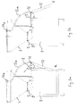
- FIGS. 1a, b show a filling machine 1 for filling and portioning pasty mass, in the present example of sausage meat.
- the filling machine 1 has a hopper 2 , in which a rotatable feeder 3 is arranged in the form of a circulating feeder curve, at the upper end of a scraper 4 is mounted to solve the (not shown) sausage meat from the inner edge of the hopper 2.
- the feed curve 3 conveys the sausage meat toward the middle and down to a conveyor 5.
- the filling machine 1 is designed as a vacuum filler, ie the hopper 2 is closed and in the conveyor 5, a negative pressure is generated by means of a (not shown) vacuum pump, which causes the pasty mass is sucked into delivery chambers of the conveyor 5 and thereby portioned.
- the portioned sausage meat is then ejected via a filling tube 6 , which is formed on the base body 7 of the filling machine 1, in (not shown) sausage casings.
- a base 8 in the form of a walk-platform is attached to the base body 7 of the filling machine 1.
- a distance A1 between the standing platform 8 and the upper edge of the hopper 2 is selected so that standing on the platform platform 8 operator can completely clean the hopper 2, ie the top of the hopper 2 is approximately at waist level, so that the operator Hopper 2 can clean down to the conveyor 5.
- the distance A1 between the standing platform 8 and the upper edge of the hopper 2 is typically less than 130 cm, preferably less than 120 cm, in particular less than 100 cm.
- distance A1 should not be too low to meet the requirements of standard EN 12463: 2004, which stipulates that the distance A1 must be at least 110 cm for funnel diameters D of 110 cm or more, whereas for hopper Diameters of less than 110 cm, the distance A1 not less than 70 cm may be chosen.
- the lock of the drives 12, 13 can be solved, however, if an operator located on the platform at the same time two switches 14a, 14b of a two-hand circuit 14 (see. Fig. 1 b) activated, which are arranged in the present example at the upper ends of handrails 15a, 15b , which extend along opposite edges of the ladder 10 and give the operator on the standing platform 8 additional security.
- another operator can activate the drive 12 of the conveyor or the drive 13 of the feed curve 3 in order to eject sausage meat present in the filling funnel 2 via the filling tube 6.
- the two-hand control circuit 14 also fulfills an additional function:
- the control signal transmitted to the control device 11 when the switches 14a, 14b are actuated simultaneously also serves to set the drive 13 of the feed-in curve 3 to rotate slowly, so that the platform 8 on the platform 8 Standing operator can clean the hopper 2 in areas that were hidden from the feed curve 3 before rotation.
- the control device 11 can be implemented here in the form of hardware and / or software components. These components are designed so that during the entire period in which the switches 14a, 14b are actuated simultaneously, the feed cam 3 rotates.
- the control device 11 can also activate the drive 12 of the conveyor 5 in order to set the conveyor in a (slow) rotational movement. This makes it possible to discharge pasty mass, which was brought by the operator into the filling chambers of the conveyor 5 during the cleaning process, via the filling tube 6. It is understood that upon actuation of the switches 14a, 14b does not necessarily have to be a rotation of the conveyor 5, ie it is also possible that when pressing the switch 14a, 14b only a rotation of the feed curve 3 takes place. In this case, after completion of the cleaning process, the conductor 10 in the rest position R spent and subsequently the conveyor 5 are activated on a (not shown) operating unit to eject the spent during the cleaning process in the filling chambers sausage meat on the filling tube 6.
- the operator releases at least one switch 14a, 14b of the two-hand control 14, whereby the machine functions can be deactivated and the hopper 2 can be further cleaned.
- the operator standing on the platform 8 can perform a complete cleaning of the hopper 2, i. a cleaning even in the areas that were covered by the feeder curve 3 before twisting, without having to leave the standing platform 8 for this purpose.
- FIGS. 1a, b the entire footprint 8 is formed in the form of a walk-platform at the top of the main body 7 of the filling machine 1. But this is not absolutely necessary, but the floor space can also be shared, as in the following in connection with FIGS. 2a -c is described.
- the standing platform 8 shown there forms only about 2/3 of the stand area, while the remaining third of the floor space is a pivotable portion 8a , which is coupled to the upper end of the conductor 10 or rigidly connected to this and together with this around a joint 16 can be turned.
- the portion 8a may be formed, for example, as a grid and closes with the ladder 10 typically one Angle greater than 90 °. In this way it can be achieved that the pivotable portion 8a in the rest position R (see. Fig. 2a ) of the conductor 10 at an angle ⁇ 'of about 25 ° or more to the horizontal, ie, an operator in the rest position R is not accessible.
- Fig. 2a is the pivotable portion 8a in the rest position R up over the machine body 7, which makes it even more difficult or impossible for the operator to enter the standing platform 8, without the ladder 10 from the rest position R in the position of use G to pivot.
- the angle ⁇ ' which includes the pivotable portion 8a with the horizontal, as large as possible, it is advantageous if the main body 7 of the filling machine 1, a recess 17 (see. Fig. 2c ) for receiving the lower end of the conductor 10 has.
- the pivotable portion 8a is additionally extended by a peripheral frame, which is required according to the cited standard (Section 5.3.2.1.8.1) to secure the footprint (and have a height of about 15 mm should).
- the entire pivotable portion 8a (including frame) thus corresponds to the entire surface of the base and thus typically has dimensions of about 500 mm x 400 mm or above, as prescribed in the cited standard.
- the entire footprint 8 may be coupled to the conductor 10 and pivoted with this about the hinge 16. In this way it is ensured that the operator can under no circumstances use the top of the main body 7 as a standing surface, without the ladder 10 in the in Fig. 3b shown use position G to move. It is understood that the floor space 8 is different than in Fig. 3b shown in the position of use G can also rest on the top of the main body 7 of the filling machine 1.
- FIGS. 4a, b Another way to safely prevent the walking of the floor space without moving the ladder 10 in the position of use G is in FIGS. 4a, b shown.
- FIGS. 3a, b Here is the entire floor space together with the ladder 10th pivotable; However, only a first portion 8a of the base is rigidly coupled to the conductor 10, while a second portion 8b of the base is connected via a further joint 18 to the first portion 8a.
- the operator can not commit in this case, in the rest position R, the subregions 8a, 8b of the stand area.
Landscapes
- Life Sciences & Earth Sciences (AREA)
- Engineering & Computer Science (AREA)
- Wood Science & Technology (AREA)
- Zoology (AREA)
- Food Science & Technology (AREA)
- Basic Packing Technique (AREA)
- Supply Of Fluid Materials To The Packaging Location (AREA)
- Meat, Egg Or Seafood Products (AREA)
Abstract
Description
Die vorliegende Erfindung betrifft eine Füllmaschine zum Abfüllen pastöser Masse, umfassend: einen Fülltrichter, in dem eine drehbare Zuführeinrichtung zum Zuführen der pastösen Masse zu einem Förderwerk angebracht ist, eine bewegliche Tritthilfe für einen Bediener, die in einer Gebrauchsstellung das Erreichen einer Standfläche zur Reinigung des Fülltrichters ermöglicht, wobei in der Gebrauchsstellung die Zuführeinrichtung gegen Verdrehen verriegelt ist, sowie eine im Bereich der Standfläche angeordnete Zweihandschaltung, die beim Betätigen die Verriegelung aufhebt.The present invention relates to a filling machine for filling pasty mass, comprising: a hopper in which a rotatable feeder is mounted for supplying the pasty mass to a conveyor, a movable tread aid for an operator, in a position of use reaching a footprint for cleaning the Filling funnel allows, wherein in the position of use, the feeding device is locked against rotation, as well as arranged in the area of the footprint two-hand circuit that cancels the lock when you press.
Füllmaschinen, bei denen eine pastöse Masse, z.B. in Form von Wurstbrät, über einen Fülltrichter unter Zuhilfenahme einer Zuführeinrichtung einem Förderwerk zugeführt wird, um die mittels des Förderwerks portionierte Masse über ein Füllrohr z.B. in Wursthüllen auszustoßen, sind aus dem Stand der Technik bekannt.Filling machines in which a pasty mass, e.g. in the form of sausage meat, is fed via a hopper with the aid of a feeder to a conveyor to the portioned by means of the conveyor mass via a filling tube, e.g. To eject in sausage casings, are known from the prior art.
An derartige Füllmaschinen sind hohe Sicherheits- und Hygieneanforderungen zu stellen, die in der Europäischen Norm EN 12463:2004 dargestellt sind. So ist beispielsweise in Abschnitt 5.3.2.1.9.1 dieser Norm angegeben, dass Auftritte oder Leitern, von denen aus Gefahrenstellen innerhalb des Fülltrichters erreichbar sind, verriegelt sein müssen. Werden die Auftritte oder Leitern in eine Gebrauchsstellung bewegt, wird die Verriegelung aktiviert und die Maschinenfunktionen werden gesperrt, d.h. es werden insbesondere das Förderwerk und die drehbare Zuführeinrichtung deaktiviert, um einen auf einer Standfläche der Auftritte oder Leitern stehenden Bediener, der von der Standfläche aus das Innere des Fülltrichters erreichen kann, vor beweglichen Teilen zu schützen.Such filling machines have to meet high safety and hygiene requirements, which are described in the European standard EN 12463: 2004. For example, section 5.3.2.1.9.1 of this standard specifies that lanes or ladders from which danger points within the hopper are accessible must be interlocked. When the slides or ladders are moved to a use position, the lock is activated and the machine functions are disabled, i. in particular, the conveyor and the rotatable feeder are deactivated in order to protect an operator standing on a standing surface of the slides or ladders, who can reach the interior of the filling funnel from the standing surface, against moving parts.
Da der Bediener beim Betätigen einer Zweihandschaltung am Rand des Fülltrichters mit seinen Armen bzw. Händen nicht an die Gefahrenstellen in dem Fülltrichter herankommen kann, kann die Verriegelung bei der Betätigung der Zweihandschaltung aufgehoben werden, wie in Abschnitt 5.3.2.1.9.2 der Europäischen Norm dargestellt ist. Das Aufheben der Verriegelung ist insbesondere bei einer Reinigung des Fülltrichters beim Chargenwechsel günstig, bei der vermieden werden soll, dass es zu einer Vermischung unterschiedlicher Brätsorten von aufeinander folgenden Chargen kommt.Since the operator can not approach the danger points in the hopper when operating a two-hand control on the edge of the hopper, the lock can be lifted when operating the two-hand control, as shown in section 5.3.2.1.9.2 of the European Standard is. The release of the lock is particularly favorable when cleaning the hopper when batch change, in which it should be avoided that it comes to a mix of different types of cakes of successive batches.
Bei einem solchen Chargenwechsel steigt ein erster Bediener auf die Standfläche der Füllmaschine und kratzt mittels eines Werkzeugs die Brätreste in dem Fülltrichter zusammen, wobei er diese nach unten in den Förderwerksbereich drückt. Der erste Bediener aktiviert dann die Zweihandschaltung, um die Verriegelung aufzuheben und das Förderwerk und ggf. weitere Maschinenfunktionen für einen weiteren Bediener aktivierbar zu machen, der sich an einer Bedieneinheit der Füllmaschine befindet, von der aus der Fülltrichter nicht zugänglich ist.In such a batch change, a first operator climbs onto the footprint of the filling machine and, by means of a tool, scrapes the leftovers in the hopper, pushing them down into the conveyor area. The first operator then activates the two-hand control to release the lock and make the conveyor and possibly other machine functions activatable for another operator who is located on an operating unit of the filling machine, from which the hopper is not accessible.
Der weitere Bediener aktiviert dann das Förderwerk und fährt dieses so lange leer, bis kein Wurstbrät mehr durch das Füllrohr ausgestoßen wird. Zusätzlich kann hierbei durch den weiteren Bediener auch die Zuführeinrichtung in dem Fülltrichter gedreht werden, so dass auch derjenige Bereich in dem Fülltrichter für den ersten Bediener zugänglich wird, der vor der Drehung von der Zuführeinrichtung verdeckt war. Der oben beschriebene Arbeitsvorgang kann sich ggf. mehrmals wiederholen, bis das gesamte Wurstbrät aus dem Fülltrichter entfernt worden ist.The other operator then activates the conveyor and runs this empty until no sausage meat is expelled through the filling tube. In addition, in this case by the other operator and the feeder can be rotated in the hopper, so that the area in the hopper for the first operator is accessible, which was covered by the supply before the rotation. The above-described operation may possibly be repeated several times until the entire sausage meat has been removed from the hopper.
Es ist die Aufgabe der vorliegenden Erfindung, eine Füllmaschine der eingangs genannten Art dahingehend weiterzubilden, dass die Reinigung des Fülltrichters vereinfacht und verbessert bzw. die Sicherheit beim Reinigen des Fülltrichters erhöht wird.It is the object of the present invention to develop a filling machine of the type mentioned in such a way that the cleaning of the hopper simplifies and improves or safety when cleaning the hopper is increased.
Diese Aufgabe wird gemäß einem ersten Aspekt gelöst durch eine Füllmaschine, bei der die Zweihandschaltung mit einer Steuerungseinrichtung zur Ansteuerung eines Antriebs der Zuführeinrichtung verbunden ist, wobei die Steuerungseinrichtung ausgebildet bzw. programmiert ist, beim Betätigen der Zweihandschaltung bzw. bei betätigter Zweihandschaltung den Antrieb der Zuführeinrichtung zu aktivieren, um eine (langsame) Drehung der Zuführeinrichtung zu bewirken. Auf diese Weise kann der Bediener, der auf der Standfläche steht, durch Aktivierung der Zweihandschaltung die Winkel-Stellung der Zuführeinrichtung in dem Fülltrichter direkt beeinflussen und den Fülltrichter auch in Abschnitten reinigen, die von der Zuführeinrichtung vor dem Verdrehen verdeckt wurden.This object is achieved according to a first aspect by a filling machine in which the two-hand control is connected to a control device for controlling a drive of the feeder, wherein the control device is designed or programmed, the actuation of the two-handed circuit or when operated two-hand control the drive of the feeder to activate to cause a (slow) rotation of the feeder. In this way, by activating the two-hand control, the operator standing on the platform can directly influence the angular position of the feeder in the hopper and also clean the hopper in sections that have been covered by the feeder before twisting.
Eine Reinigung des Fülltrichters beim Chargenwechsel kann somit durch einen einzigen Bediener erfolgen. Insbesondere kann hierbei vermieden werden, dass der Bediener zunächst von der Füllmaschine herabsteigen, die Tritthilfe aus der Gebrauchsstellung bewegen und sich zu einer Bedieneinheit der Füllmaschine begeben muss, um eine Veränderung der Winkel-Stellung der Zuführeinrichtung zu bewirken, wobei er anschließend die Tritthilfe wieder in die Gebrauchsstellung überführen muss, um von der Standfläche aus den Fülltrichter weiter reinigen zu können. Auf diesen zeitaufwändigen Vorgang wird der Bediener in der Regel verzichten und stattdessen eine geringfügige Vermischung der pastösen Massen in Kauf nehmen, wodurch aber die Qualität des Endprodukts beeinträchtigt wird.A cleaning of the hopper during batch change can thus be done by a single operator. In particular, this can be avoided that the operator first descend from the filling machine, move the treadle from the use position and must go to an operating unit of the filling machine to cause a change in the angular position of the feeder, where he then the tread aid back in the use position must be transferred in order to continue to clean the hopper from the stand. As a rule, the operator will do without this time-consuming process and instead accept a slight mixing of the pasty masses, which, however, impairs the quality of the final product.
Um während der Betätigung der Zweihandschaltung bzw. bei betätigter Zweihandschaltung eine automatische Drehung der Zuführeinrichtung zu bewirken, ist die Zweihandschaltung mit einer Steuerungseinrichtung zur Ansteuerung eines Antriebs der Zuführeinrichtung verbunden. Beim Betätigen der Zweihandschaltung wird ein Steuersignal an die Steuerungseinrichtung übermittelt, welches die Steuerungseinrichtung dazu veranlasst, den Antrieb der Zuführeinrichtung zu aktivieren. Anders als beim Füllbetrieb, bei dem die Drehung des Förderwerks mit der Drehung der Zuführeinrichtung synchronisiert und sehr schnell erfolgt, wird die Zuführeinrichtung bei der Aktivierung mit Hilfe der Zweihandschaltung mit einer vorgegebenen (Winkel-)Geschwindigkeit bewegt, die im Vergleich zur Geschwindigkeit beim Füllbetrieb wesentlich geringer ist.In order to effect an automatic rotation of the feeder during the operation of the two-hand control or when two-handed operation is operated, the two-hand control is connected to a control device for controlling a drive of the feeder. Upon actuation of the two-hand control, a control signal is transmitted to the control device, which causes the control device to activate the drive of the feed device. Unlike the filling operation, in which the rotation of the conveyor synchronized with the rotation of the feeder and takes place very quickly, the feeder is moved at the activation by means of two-hand control at a predetermined (angular) speed, which compared to the speed during filling substantially is lower.
Bevorzugt ist die Zuführeinrichtung durch eine Zubringerkurve gebildet. Die umlaufende Zubringerkurve dient der Zuführung von in dem Fülltrichter vorhandenem Wurstbrät zur Mitte hin und nach unten zum Förderwerk. An der Außenseite der Zubringerkurve befindet sich in der Regel ein Schaber, der das Wurstbrät vom Trichterrand löst. Es versteht sich, dass zusätzlich oder alternativ zur Zubringerkurve auch andere Zuführeinrichtungen, beispielsweise Förderschnecken oder dergleichen in dem Fülltrichter angeordnet sein können. Auch diese können ggf. durch die Zweihandschaltung in Drehung versetzt werden.Preferably, the feed device is formed by a feeder curve. The circulating feeder curve serves to feed sausage meat present in the hopper to the middle and down to the conveyor. On the outside of the feeder curve is usually a scraper, which dissolves the sausage meat from the funnel edge. It goes without saying that, in addition to or as an alternative to the feed curve, other feed devices, for example screw conveyors or the like, can also be arranged in the hopper. These may also be rotated by the two-handed circuit, if necessary.
Es hat sich als günstig erwiesen, wenn sich die Zuführeinrichtung mit einer insbesondere konstanten Drehzahl von weniger als 5 Umdrehungen/min, bevorzugt von weniger als 3 Umdrehungen/min dreht, während die Zweihandschaltung aktiviert ist. Bei diesen Drehzahlen kann die Zuführeinrichtung vom Bediener mit ausreichender Präzision in die gewünschte Winkel-Stellung gebracht werden.It has proved to be advantageous if the feeder rotates at a particularly constant speed of less than 5 revolutions / min, preferably less than 3 revolutions / min, while the two-hand control is activated. At these speeds, the feeder can be brought by the operator with sufficient precision in the desired angular position.
Es ist ebenfalls günstig, wenn die Zuführeinrichtung bei aktivierter Zweihandschaltung mit einer insbesondere konstanten Drehzahl von mindestens 0,5 Umdrehungen/min, bevorzugt von mindestens 1 Umdrehung/min gedreht wird. Durch die Wahl von Drehzahlen, die größer als die oben genannten Minimaldrehzahlen sind, wird sichergestellt, dass der Bediener die Zuführeinrichtung rasch in die gewünschte Winkel-Stellung verbringen kann, so dass die Reinigung des Fülltrichters beschleunigt wird.It is also advantageous if the feeding device with activated two-hand control with a particular constant speed of at least 0.5 Revolutions / min, preferably of at least 1 revolution / min is rotated. By choosing speeds greater than the above minimum speeds, it is ensured that the operator can quickly move the feeder to the desired angular position, thus speeding up the cleaning of the hopper.
In einer weiteren Ausführungsform ist die Steuerungseinrichtung zur Ansteuerung eines Antriebs des Förderwerks ausgebildet, um beim Betätigen der Zweihandschaltung den Antrieb des Förderwerks zu aktivieren und damit eine Drehung des Förderwerks zu bewirken. Die Drehung des Förderwerks kann erfolgen, um die pastöse Masse, die bei der Reinigung des Fülltrichters nach unten in den Förderwerksbereich verbracht wurde, über ein Füllrohr auszustoßen. Die Drehung des Förderwerks erfolgt hierbei typischer Weise synchron zur Drehung der Zuführeinrichtung, d.h. beim Betätigen der Zweihandschaltung werden beide Antriebe aktiviert und die Zuführeinrichtung sowie das Förderwerk drehen sich mit einer jeweiligen vorgegebenen Winkelgeschwindigkeit. Alternativ ist es selbstverständlich auch möglich, die beiden Antriebe unabhängig voneinander anzusteuern, so dass beim Betätigen der Zweihandschaltung lediglich die Zuführeinrichtung in Drehung versetzt wird.In a further embodiment, the control device is designed to control a drive of the conveyor to activate the drive of the conveyor during actuation of the two-hand control and thus to effect a rotation of the conveyor. The rotation of the conveyor can be done to eject the pasty mass, which was spent in the cleaning of the hopper down into the conveyor area, via a filling tube. The rotation of the conveyor is hereby typically synchronous with the rotation of the feeder, i. when operating the two-hand control both drives are activated and the feeder and the conveyor rotate at a respective predetermined angular velocity. Alternatively, it is of course also possible to control the two drives independently of each other, so that when operating the two-hand control only the feeder is rotated.
In einer vorteilhaften Ausführungsform ist die Standfläche durch eine Standplattform an, insbesondere auf dem Maschinengrundkörper der Füllmaschine gebildet. Das Vorsehen einer Standplattform am Maschinengrundkörper ermöglicht es, die Standfläche verhältnismäßig groß zu dimensionieren und dadurch die Sicherheit des Bedieners zu erhöhen sowie zu verhindern, dass der Bediener Bereiche an der Maschinenoberseite als Standfläche nutzt, die nicht zu diesem Zweck vorgesehen sind. Es versteht sich, dass alternativ die Standfläche lediglich an der Tritthilfe gebildet werden kann, z.B. an der obersten Stufe einer schwenkbaren Leiter.In an advantageous embodiment, the footprint is formed by a standing platform, in particular on the machine base body of the filling machine. The provision of a standing platform on the machine body makes it possible to dimension the footprint relatively large, thereby increasing the safety of the operator and to prevent the operator uses areas on the machine top as a stand area, which are not provided for this purpose. It is understood that, alternatively, the footprint can only be formed on the tread aid, e.g. at the top step of a pivotable ladder.
Ein weiterer Aspekt der Erfindung betrifft eine Füllmaschine gemäß dem Oberbegriff von Anspruch 1 bzw. mit den oben beschriebenen Merkmalen, bei der zumindest ein Teilbereich der Standfläche, insbesondere die gesamte Standfläche, mit der Tritthilfe über ein Gelenk (starr) verbunden und gemeinsam mit der Tritthilfe verschwenkbar ist. Mit Hilfe des verschwenkbaren Teilbereichs der Standfläche kann die Standfläche insgesamt größer dimensioniert werden, was insbesondere vorteilhaft ist, wenn für die Standplattform an der Oberseite des Maschinengrundkörpers nicht genügend Bauraum zur Verfügung steht.Another aspect of the invention relates to a filling machine according to the preamble of
Die Tritthilfe kann hierbei z.B. als schwenkbare Leiter ausgebildet sein. Die schwenkbare Leiter weist am oberen Ende ein Gelenk auf, um das die Leiter von der Gebrauchsstellung, in der die Leiter begehbar ist, in eine Ruhestellung verschwenkt werden kann, in der die Leiter nicht als Tritthilfe genutzt werden kann. Das Gelenk ist hierbei mit einer Steuerungseinrichtung der Füllmaschine verbunden, so dass beim Erreichen der Gebrauchsstellung der Leiter eine Verriegelung aktiviert wird, welche das Förderwerk und die Zuführeinrichtung sperrt.The treadmill can in this case e.g. be designed as a pivotable ladder. The pivotable ladder has at the upper end a joint around which the ladder can be pivoted from the position of use in which the ladder is passable into a rest position in which the ladder can not be used as a stepping aid. The joint is in this case connected to a control device of the filling machine, so that upon reaching the position of use of the ladder a lock is activated, which locks the conveyor and the feeder.
In einer besonders vorteilhaften Ausführungsform schließt der an dem Gelenk starr angebundene, verschwenkbare Teilbereich der Standfläche bzw. die gesamte Standfläche in der Ruhestellung einen Winkel von 25° oder mehr mit der Horizontalen ein und steht in der Ruhestellung nach oben über den Maschinengrundkörper über. Die Schräglage der verschwenkbaren Standfläche bzw. des verschwenkbaren Teilbereichs der Standfläche macht es für den Bediener unmöglich, diese in der Ruhestellung zu begehen. Das Gelenk, an dem die Tritthilfe an den Maschinengrundkörper angebunden ist, befindet sich typischer Weise etwa auf der Höhe der Oberseite des Grundkörpers, so dass der verschwenkbare Teilbereich in der Ruhestellung nach oben über den Grundkörper übersteht und das Erreichen des Teilbereichs der Standfläche, der als Plattform an der Oberseite des Maschinengrundkörpers ausgebildet ist, für den Bediener erschwert bzw. unmöglich macht.In a particularly advantageous embodiment, the rigidly connected to the hinge, pivotable portion of the floor space or the entire base in the rest position includes an angle of 25 ° or more with the horizontal and is in the rest position up over the machine body over. The inclined position of the pivotable base surface or of the pivotable portion of the base surface makes it impossible for the operator to commit them in the rest position. The joint on which the tread aid is connected to the machine base body is typically located approximately at the level of the upper side of the base body, so that the pivotable partial area protrudes upward beyond the base body in the rest position and the reaching of the partial area of the standing surface, as Platform is formed at the top of the machine body, made difficult or impossible for the operator.
Um letztere Funktion zu erfüllen ist es günstig, wenn der verschwenkbare Teilbereich mindestens ein Drittel der Fläche der - typischer Weise rechteckigen - Standfläche bildet. Insbesondere sollte der verschwenkbare Teilbereich nicht zu klein gewählt werden, um das unerlaubte Betreten der Standfläche durch einen Bediener wirksam verhindern zu können. Es versteht sich, dass für gewöhnlich die Tritthilfe nur in der Ruhestellung und in der Gebrauchsstellung fixierbar ist und ein Begehen bzw. Nutzen der Tritthilfe in einer Zwischenstellung nicht möglich ist.In order to fulfill the latter function, it is favorable if the pivotable subregion forms at least one third of the surface of the-typically rectangular-base surface. In particular, the pivotable portion should not be chosen too small in order to prevent the unauthorized entry of the footprint by an operator effectively. It is understood that usually the treadmill is fixable only in the rest position and in the position of use and a committing or use of the treadmill in an intermediate position is not possible.
Bei einer weiteren Ausführungsform ist ein weiterer Teilbereich der Standfläche über ein weiteres Gelenk an den mit der Tritthilfe verbundenen Teilbereich der Standfläche angebunden. In der Ruheposition der Tritthilfe verlaufen in diesem Fall beide Teilbereiche in der Art eines Daches unter einem jeweiligen Winkel zur Horizontalen und verhindern somit ebenfalls das unbefugte Betreten der Standfläche.In a further embodiment, a further portion of the standing surface is connected via a further joint to the portion of the standing surface connected to the treadmill. In the rest position of the treadmill run in this case, both sections in the manner of a roof at a respective angle to the horizontal and thus also prevent unauthorized entry to the floor space.
Bei einer besonders vorteilhaften Ausführungsform ist an gegenüberliegenden Rändern der Tritthilfe im Bereich der Standfläche jeweils ein Handlauf (Geländer) vorgesehen. Die Handläufe dienen dem sicheren Erreichen der erhöhten Standfläche und bieten dem Bediener zusätzliche Sicherheit beim Reinigen des Fülltrichters.In a particularly advantageous embodiment, a handrail (railing) is provided at opposite edges of the treadmill in the area of the footprint. The handrails are used to safely reach the increased footprint and provide additional security for the operator when cleaning the hopper.
Bei einer vorteilhaften Weiterbildung dieser Ausführungsform sind die Schalter der Zweihandschaltung an den oberen Enden der Handläufe angebracht. Auf diese Weise kann sich der Bediener bei der Betätigung der Zweihandschaltung an den Handläufen festhalten, wodurch die Sicherheit bei der Bedienung der Zweihandschaltung erhöht wird. Da die Handläufe auf gegenüberliegenden Seiten der Tritthilfe angeordnet sind, weisen diese einen ausreichenden Abstand für die Anbringung der beiden Schalter der Zweihandschaltung auf.In an advantageous development of this embodiment, the switches of the two-hand control are attached to the upper ends of the handrails. In this way, the operator can cling to the handrails when operating the two-hand control, which increases the safety when operating the two-hand control. Since the handrails are arranged on opposite sides of the treadmill, they have a sufficient distance for the attachment of the two switches of the two-hand circuit.
Bei einer weiteren Ausführungsform beträgt ein Abstand zwischen der Standfläche und dem oberen Rand des Fülltrichters weniger als 130 cm, bevorzugt weniger als 120 cm, insbesondere weniger als 100 cm. Da bei der Wahl eines solchen Abstands die Oberseite des Trichters ungefähr auf Hüfthöhe liegt, kann der Bediener den Fülltrichter vollständig, d.h. bis hinunter zum Förderwerk reinigen. Bei der Wahl eines Abstands von weniger als 110 cm darf jedoch der Durchmesser des Fülltrichters nicht größer als 110 cm sein, da ansonsten die Norm EN 12463:2004 nicht erfüllt werden kann, die festlegt, dass bei Fülltrichter-Durchmessern größer als 110 cm auch der Abstand zwischen Standfläche und oberem Rand des Fülltrichters größer als 110 cm sein muss.In a further embodiment, a distance between the standing surface and the upper edge of the filling funnel is less than 130 cm, preferably less than 120 cm, in particular less than 100 cm. Since, in choosing such a distance, the top of the funnel is approximately at waist level, the operator can fully open the hopper, i. Clean down to the conveyor. When choosing a distance of less than 110 cm, however, the diameter of the hopper may not be greater than 110 cm, as otherwise the standard EN 12463: 2004 can not be met, which stipulates that for hopper diameters greater than 110 cm and the Distance between the base and the upper edge of the hopper must be greater than 110 cm.
Typischer Weise handelt es sich bei der oben beschriebenen Füllmaschine um einen Vakuumfüller, bei dem der Fülltrichter über dem Förderwerk verschliessbar ist. Bei derartigen Füllmaschinen wird im Förderwerk mit Hilfe einer Vakuumpumpe ein Unterdruck erzeugt, der dazu führt, dass die pastöse Masse in die Förderkammern des Förderwerks gesaugt wird.Typically, the filling machine described above is a vacuum filler in which the hopper can be closed above the conveyor. In such filling machines, a vacuum is generated in the conveyor with the aid of a vacuum pump, which causes the pasty mass in the delivery chambers the conveyor is sucked.
Weitere Vorteile der Erfindung ergeben sich aus der Beschreibung und der Zeichnung. Ebenso können die vorstehend genannten und die noch weiter aufgeführten Merkmale je für sich oder zu mehreren in beliebigen Kombinationen Verwendung finden. Die gezeigten und beschriebenen Ausführungsformen sind nicht als abschließende Aufzählung zu verstehen, sondern haben vielmehr beispielhaften Charakter für die Schilderung der Erfindung.Further advantages of the invention will become apparent from the description and the drawings. Likewise, the features mentioned above and the features listed further can be used individually or in combination in any combination. The embodiments shown and described are not to be understood as exhaustive enumeration, but rather have exemplary character for the description of the invention.
Es zeigen:
- Fign. 1 a,b
- schematische Darstellungen einer Ausführungsform einer erfindungsgemäßen Füllmaschine jeweils in einer Seitenansicht
- Fign. 2a-c
- schematische Darstellungen einer Ausführungsform der Füllmaschine mit einer Standfläche mit einem verschwenkbaren Teilbereich, der mit einer Leiter gekoppelt ist,
- Fign. 3a,b
- schematische Darstellungen einer weiteren Ausführungsform der Füllmaschine, bei der die gesamte Standfläche verschwenkbar ist, und
- Fign. 4a,b
- schematische Darstellungen einer Ausführungsform der Füllmaschine, bei der zwei Teilbereiche der Standfläche über ein Gelenk miteinander verbunden sind.
- FIGS. 1 a, b
- schematic representations of an embodiment of a filling machine according to the invention in each case in a side view
- FIGS. 2a-c
- schematic representations of an embodiment of the filling machine with a footprint with a pivotable portion which is coupled to a ladder,
- FIGS. 3a, b
- schematic representations of another embodiment of the filling machine in which the entire base surface is pivotable, and
- FIGS. 4a, b
- schematic representations of an embodiment of the filling machine, in which two portions of the base are connected to each other via a hinge.
Im vorliegenden Beispiel ist die Füllmaschine 1 als Vakuum-Füller ausgebildet, d.h. der Fülltrichter 2 ist verschließbar und im Förderwerk 5 wird mit Hilfe einer (nicht gezeigten) Vakuumpumpe ein Unterdruck erzeugt, der dazu führt, dass die pastöse Masse in Förderkammern des Förderwerks 5 gesaugt und dadurch portioniert wird. Das portionierte Wurstbrät wird dann über ein Füllrohr 6, das am Grundkörper 7 der Füllmaschine 1 gebildet ist, in (nicht gezeigte) Wursthüllen ausgestoßen.In the present example, the filling
Um den Fülltrichter 2 bei einem Chargenwechsel zu reinigen, ist an dem Grundkörper 7 der Füllmaschine 1 eine Standfläche 8 in Form einer begehbaren Plattform angebracht. Die Plattform 8, die zum Boden 9, auf dem die Füllmaschine 1 aufgestellt ist, einen Abstand A0 von beispielsweise 120 cm aufweist, kann über eine Tritthilfe 10 erreicht werden, die im vorliegenden Beispiel als schwenkbare Leiter ausgebildet ist.In order to clean the
Hierbei ist ein Abstand A1 zwischen der Standplattform 8 und dem oberen Rand des Fülltrichters 2 so gewählt, dass der auf der Standplattform 8 stehende Bediener den Fülltrichter 2 vollständig reinigen kann, d.h. die Oberseite des Fülltrichters 2 liegt ungefähr auf Hüfthöhe, so dass der Bediener den Fülltrichter 2 bis hinunter zum Förderwerk 5 reinigen kann. Der Abstand A1 zwischen der Standplattform 8 und dem oberen Rand des Fülltrichters 2 beträgt hierbei typischer Weise weniger als 130 cm, bevorzugt bei weniger als 120 cm, insbesondere weniger als 100 cm. Der Abstand A1 sollte aber nicht zu gering gewählt werden, um den Anforderungen der Norm EN 12463:2004 zu genügen, welche vorschreibt, dass der Abstand A1 bei Fülltrichter-Durchmessern D von 110 cm oder darüber mindestens 110 cm betragen muss, während bei Fülltrichter-Durchmessern von weniger als 110 cm der Abstand A1 nicht kleiner als 70 cm gewählt werden darf.Here, a distance A1 between the standing
Um die Leiter 10 begehbar zu machen, muss diese aus einer in
Die Sperre der Antriebe 12, 13 kann jedoch gelöst werden, falls ein auf der Plattform befindlicher Bediener gleichzeitig zwei Schalter 14a, 14b einer Zweihandschaltung 14 (vgl.
Im vorliegenden Beispiel erfüllt die Zweihandschaltung 14 noch eine zusätzliche Funktion: Das beim simultanen Betätigen der Schalter 14a, 14b an die Steuerungseinrichtung 11 übermittelte Steuerungssignal dient auch dazu, den Antrieb 13 der Zubringerkurve 3 in eine langsame Drehung zu versetzen, damit der auf der Plattform 8 stehende Bediener den Fülltrichter 2 auch in Bereichen reinigen kann, die vor der Drehung von der Zubringerkurve 3 verdeckt waren. Die Steuerungseinrichtung 11 kann hierbei in Form von Hardware- und/oder Softwarekomponenten implementiert sein. Diese Komponenten sind so ausgelegt bzw. so programmiert, dass sich während des gesamten Zeitraums, in dem die Schalter 14a, 14b simultan betätigt werden, die Zubringerkurve 3 dreht.In the present example, the two-
Zusätzlich kann beim simultanen Betätigen der Schalter 14a, 14b die Steuerungseinrichtung 11 auch den Antrieb 12 des Förderwerks 5 aktivieren, um das Förderwerk in eine (langsame) Drehbewegung zu versetzen. Dies ermöglicht es, pastöse Masse, die beim Reinigungsprozess vom Bediener in die Füllkammern des Förderwerks 5 verbracht wurde, über das Füllrohr 6 auszustoßen. Es versteht sich, dass beim Betätigen der Schalter 14a, 14b nicht zwingend eine Drehung des Förderwerks 5 erfolgen muss, d.h. es ist auch möglich, dass beim Betätigen der Schalter 14a, 14b lediglich eine Drehung der Zubringerkurve 3 erfolgt. In diesem Fall kann nach dem Abschluss des Reinigungsvorgangs die Leiter 10 in die Ruheposition R verbracht und nachfolgend das Förderwerk 5 an einer (nicht gezeigten) Bedieneinheit aktiviert werden, um das beim Reinigungsvorgang in die Füllkammern verbrachte Wurstbrät über das Füllrohr 6 auszustoßen.In addition, when the
Es hat sich gezeigt, dass für das Einstellen einer gewünschten Winkel-Position der Zubringerkurve 3 durch Aktivierung der Zweihandschaltung 14 Drehzahlen günstig sind, die zwischen einer minimalen Drehzahl von 0,5 Umdrehungen/min, bevorzugt von 1 Umdrehung/min und einer maximalen Drehzahl von 5 Umdrehungen/min, bevorzugt von 3 Umdrehungen/min liegen, wobei die Drehzahl in der Regel konstant gewählt wird. Durch die Wahl einer Drehzahl, welche die oben angegebenen Maximal-Drehzahlen nicht überschreitet, kann der Bediener die Zubringerkurve 3 mit der gewünschten Genauigkeit positionieren. Durch die Wahl von Drehzahlen, welche die oben angegebenen Minimal-Drehzahlen nicht unterschreiten, wird erreicht, dass die Bewegung der Zubringerkurve 3 nicht zu lange dauert, so dass die Reinigung zügig durchgeführt werden kann.It has been found that for setting a desired angular position of the
Sobald die Zubringerkurve 3 die gewünschte Winkel-Position eingenommen hat, lässt der Bediener mindestens einen Schalter 14a, 14b der Zweihandschaltung 14 los, wodurch die Maschinenfunktionen deaktiviert werden und der Fülltrichter 2 weiter gereinigt werden kann. Auf diese Weise kann erreicht werden, dass der auf der Standplattform 8 stehende Bediener eine vollständig Reinigung des Fülltrichters 2 vornehmen kann, d.h. eine Reinigung auch in den Bereichen, die von der Zubringerkurve 3 vor dem Verdrehen verdeckt waren, ohne dass er zu diesem Zweck die Standplattform 8 verlassen muss.As soon as the
In
Wie
Alternativ zu der in
Wie in
Eine weitere Möglichkeit, das Begehen der Standfläche ohne Verbringen der Leiter 10 in die Gebrauchsstellung G sicher zu verhindern, ist in
Die oben beschriebenen Maßnahmen zur Verhinderung der unerlaubten Benutzung der Standfläche sind insbesondere im Zusammenhang mit dem Vorsehen der Handläufe 15a, 15b günstig, da diese ggf. einen Benutzer dazu verleiten könnten, unerlaubter Weise auf die Standfläche zu klettern, ohne die Leiter 10 in die Gebrauchstellung G zu verbringen.The above-described measures for preventing the unauthorized use of the footprint are particularly favorable in connection with the provision of the
Claims (13)
Applications Claiming Priority (1)
| Application Number | Priority Date | Filing Date | Title |
|---|---|---|---|
| DE201010028683 DE102010028683A1 (en) | 2010-05-06 | 2010-05-06 | Filling machine for filling pasty mass |
Publications (3)
| Publication Number | Publication Date |
|---|---|
| EP2384635A2 true EP2384635A2 (en) | 2011-11-09 |
| EP2384635A3 EP2384635A3 (en) | 2013-01-02 |
| EP2384635B1 EP2384635B1 (en) | 2013-10-02 |
Family
ID=44366855
Family Applications (1)
| Application Number | Title | Priority Date | Filing Date |
|---|---|---|---|
| EP20110164769 Not-in-force EP2384635B1 (en) | 2010-05-06 | 2011-05-04 | Filling machine for filling paste masses |
Country Status (2)
| Country | Link |
|---|---|
| EP (1) | EP2384635B1 (en) |
| DE (1) | DE102010028683A1 (en) |
Cited By (2)
| Publication number | Priority date | Publication date | Assignee | Title |
|---|---|---|---|---|
| EP2586314A1 (en) * | 2011-10-25 | 2013-05-01 | Albert Handtmann Maschinenfabrik GmbH & Co. KG | Food machine, in particular machine for processing and producing sausage and method for operating same |
| EP2965630A1 (en) * | 2014-07-08 | 2016-01-13 | Albert Handtmann Maschinenfabrik GmbH & Co. KG | Filling machine and method for interim cleaning of a filling machine |
Family Cites Families (4)
| Publication number | Priority date | Publication date | Assignee | Title |
|---|---|---|---|---|
| DE3617495C2 (en) * | 1986-05-24 | 1996-04-11 | Schnell Maschfab Karl | Conveying device especially for rigid masses |
| US5092528A (en) * | 1987-09-24 | 1992-03-03 | Cozzini, Inc. | Meat emulsifying and processing system |
| DK39090D0 (en) * | 1990-02-14 | 1990-02-14 | Slagteriernes Forskningsinst | PROCEDURE FOR LOOSING AND EXTRACTING BONE FROM A CARP AND APPARATUS FOR USING THE PROCEDURE |
| EP1674416B1 (en) * | 2004-12-23 | 2008-02-13 | ThyssenKrupp Aufzugswerke GmbH | Elevator and elevator car |
-
2010
- 2010-05-06 DE DE201010028683 patent/DE102010028683A1/en not_active Ceased
-
2011
- 2011-05-04 EP EP20110164769 patent/EP2384635B1/en not_active Not-in-force
Non-Patent Citations (1)
| Title |
|---|
| None |
Cited By (6)
| Publication number | Priority date | Publication date | Assignee | Title |
|---|---|---|---|---|
| EP2586314A1 (en) * | 2011-10-25 | 2013-05-01 | Albert Handtmann Maschinenfabrik GmbH & Co. KG | Food machine, in particular machine for processing and producing sausage and method for operating same |
| US8899117B2 (en) | 2011-10-25 | 2014-12-02 | Albert Handtmann Maschinenfabrik Gmbh & Co. Kg | Food machine, in particular machine for processing and producing sausage, and method of operating the same |
| EP2586314B1 (en) * | 2011-10-25 | 2017-01-18 | Albert Handtmann Maschinenfabrik GmbH & Co. KG | Food machine, in particular machine for processing and producing sausage and method for operating same |
| EP2965630A1 (en) * | 2014-07-08 | 2016-01-13 | Albert Handtmann Maschinenfabrik GmbH & Co. KG | Filling machine and method for interim cleaning of a filling machine |
| JP2016016402A (en) * | 2014-07-08 | 2016-02-01 | アルベルト ハントマン マシネンファブリク ゲーエムベーハー ウントツェーオー.カーゲー | Filling machine, and method for intermediately cleaning filling machine |
| US10022754B2 (en) | 2014-07-08 | 2018-07-17 | Albert Handtmann Maschinenfabrik, GMBH & CO., KG | Filling machine and method for intermediate cleaning of a filling machine |
Also Published As
| Publication number | Publication date |
|---|---|
| DE102010028683A1 (en) | 2011-11-10 |
| EP2384635B1 (en) | 2013-10-02 |
| EP2384635A3 (en) | 2013-01-02 |
Similar Documents
| Publication | Publication Date | Title |
|---|---|---|
| EP3771493A1 (en) | Rock processing machine | |
| EP3595973B1 (en) | System with alternative filling of containers and method therefor | |
| WO2008052529A1 (en) | Device and method for applying an adhesive material to a tile or a tile-like plate | |
| EP3165355A1 (en) | Method for operating a rotary tablet press and rotary tablet press | |
| EP2384635B1 (en) | Filling machine for filling paste masses | |
| DE102017216809A1 (en) | Egg-separation plant | |
| EP3515783B1 (en) | Rail vehicle, method for producing a rail vehicle, and use of a scissor mechanism in a boarding arrangement | |
| EP3094184A1 (en) | Baking device and removal device | |
| EP3302922B1 (en) | Extrusion device and extrusion method for producing a plastic film | |
| EP3302924B1 (en) | Method for preparing for a change of material in an extrusion device for a film machine | |
| EP3736046B1 (en) | Retraction prevention | |
| DE10222760A1 (en) | Mughal machine and process for the manufacture of products cast in powder | |
| EP3302921B1 (en) | Extrusion device and extrusion method for producing a plastic film | |
| EP3017922B1 (en) | Method for monitoring the machinery space of a processing machine, especially of a moulder, and processing machine, in particular a moulder, for carrying out such a method | |
| EP3175748B1 (en) | Beverage preparation device, system and method of operation | |
| EP2325117A1 (en) | Device for loading and unloading a processing unit with blanks | |
| DE102007052378A1 (en) | Mortar mixing- and conveying device i.e. compulsory mixer, for use during building construction, has mixing and storage container in which dry aggregates are mixed with liquid bonding agents in loads in wet operation | |
| DE918374C (en) | Device for pressing a coating onto tablet cores or the like. | |
| EP3475174B1 (en) | Container handling machine for processing packaging materials | |
| DE2523374A1 (en) | Continuous mortar mixer with endless screw metering dry mix - has partly filled mixing chamber with water inlet and screw discharge | |
| EP2081759B1 (en) | High power rotational cycle moulding method and device | |
| EP2925149A1 (en) | Motif roll, dough-forming machine and method for producing a baked item | |
| DE202006016922U1 (en) | Device for applying an adhesive material to a tile or tile-like plate | |
| CH712621A2 (en) | Mixer with single filling and continuous product dispensing. | |
| DE19525817A1 (en) | Dispensing device for pourable product - comprises dosage chamber, which can be locked at upper and lower opening through slides, and whose fill volume is variably adjustable within predetermined range |
Legal Events
| Date | Code | Title | Description |
|---|---|---|---|
| AK | Designated contracting states |
Kind code of ref document: A2 Designated state(s): AL AT BE BG CH CY CZ DE DK EE ES FI FR GB GR HR HU IE IS IT LI LT LU LV MC MK MT NL NO PL PT RO RS SE SI SK SM TR |
|
| AX | Request for extension of the european patent |
Extension state: BA ME |
|
| PUAI | Public reference made under article 153(3) epc to a published international application that has entered the european phase |
Free format text: ORIGINAL CODE: 0009012 |
|
| PUAL | Search report despatched |
Free format text: ORIGINAL CODE: 0009013 |
|
| AK | Designated contracting states |
Kind code of ref document: A3 Designated state(s): AL AT BE BG CH CY CZ DE DK EE ES FI FR GB GR HR HU IE IS IT LI LT LU LV MC MK MT NL NO PL PT RO RS SE SI SK SM TR |
|
| AX | Request for extension of the european patent |
Extension state: BA ME |
|
| RIC1 | Information provided on ipc code assigned before grant |
Ipc: A22C 11/08 20060101AFI20121126BHEP |
|
| 17P | Request for examination filed |
Effective date: 20130201 |
|
| GRAP | Despatch of communication of intention to grant a patent |
Free format text: ORIGINAL CODE: EPIDOSNIGR1 |
|
| INTG | Intention to grant announced |
Effective date: 20130426 |
|
| GRAS | Grant fee paid |
Free format text: ORIGINAL CODE: EPIDOSNIGR3 |
|
| RAP1 | Party data changed (applicant data changed or rights of an application transferred) |
Owner name: KARL SCHNELL GMBH & CO. KG |
|
| GRAA | (expected) grant |
Free format text: ORIGINAL CODE: 0009210 |
|
| AK | Designated contracting states |
Kind code of ref document: B1 Designated state(s): AL AT BE BG CH CY CZ DE DK EE ES FI FR GB GR HR HU IE IS IT LI LT LU LV MC MK MT NL NO PL PT RO RS SE SI SK SM TR |
|
| REG | Reference to a national code |
Ref country code: GB Ref legal event code: FG4D Free format text: NOT ENGLISH |
|
| REG | Reference to a national code |
Ref country code: CH Ref legal event code: EP Ref country code: CH Ref legal event code: NV Representative=s name: RIEDERER HASLER AND PARTNER PATENTANWAELTE AG, LI Ref country code: AT Ref legal event code: REF Ref document number: 634165 Country of ref document: AT Kind code of ref document: T Effective date: 20131015 |
|
| REG | Reference to a national code |
Ref country code: IE Ref legal event code: FG4D Free format text: LANGUAGE OF EP DOCUMENT: GERMAN |
|
| REG | Reference to a national code |
Ref country code: DE Ref legal event code: R096 Ref document number: 502011001419 Country of ref document: DE Effective date: 20131128 |
|
| REG | Reference to a national code |
Ref country code: NL Ref legal event code: VDEP Effective date: 20131002 |
|
| PG25 | Lapsed in a contracting state [announced via postgrant information from national office to epo] |
Ref country code: SI Free format text: LAPSE BECAUSE OF FAILURE TO SUBMIT A TRANSLATION OF THE DESCRIPTION OR TO PAY THE FEE WITHIN THE PRESCRIBED TIME-LIMIT Effective date: 20131002 |
|
| REG | Reference to a national code |
Ref country code: LT Ref legal event code: MG4D |
|
| PG25 | Lapsed in a contracting state [announced via postgrant information from national office to epo] |
Ref country code: NL Free format text: LAPSE BECAUSE OF FAILURE TO SUBMIT A TRANSLATION OF THE DESCRIPTION OR TO PAY THE FEE WITHIN THE PRESCRIBED TIME-LIMIT Effective date: 20131002 Ref country code: HR Free format text: LAPSE BECAUSE OF FAILURE TO SUBMIT A TRANSLATION OF THE DESCRIPTION OR TO PAY THE FEE WITHIN THE PRESCRIBED TIME-LIMIT Effective date: 20131002 Ref country code: CZ Free format text: LAPSE BECAUSE OF FAILURE TO SUBMIT A TRANSLATION OF THE DESCRIPTION OR TO PAY THE FEE WITHIN THE PRESCRIBED TIME-LIMIT Effective date: 20131002 Ref country code: SE Free format text: LAPSE BECAUSE OF FAILURE TO SUBMIT A TRANSLATION OF THE DESCRIPTION OR TO PAY THE FEE WITHIN THE PRESCRIBED TIME-LIMIT Effective date: 20131002 Ref country code: FI Free format text: LAPSE BECAUSE OF FAILURE TO SUBMIT A TRANSLATION OF THE DESCRIPTION OR TO PAY THE FEE WITHIN THE PRESCRIBED TIME-LIMIT Effective date: 20131002 Ref country code: LT Free format text: LAPSE BECAUSE OF FAILURE TO SUBMIT A TRANSLATION OF THE DESCRIPTION OR TO PAY THE FEE WITHIN THE PRESCRIBED TIME-LIMIT Effective date: 20131002 Ref country code: IS Free format text: LAPSE BECAUSE OF FAILURE TO SUBMIT A TRANSLATION OF THE DESCRIPTION OR TO PAY THE FEE WITHIN THE PRESCRIBED TIME-LIMIT Effective date: 20140202 Ref country code: NO Free format text: LAPSE BECAUSE OF FAILURE TO SUBMIT A TRANSLATION OF THE DESCRIPTION OR TO PAY THE FEE WITHIN THE PRESCRIBED TIME-LIMIT Effective date: 20140102 |
|
| PG25 | Lapsed in a contracting state [announced via postgrant information from national office to epo] |
Ref country code: PL Free format text: LAPSE BECAUSE OF FAILURE TO SUBMIT A TRANSLATION OF THE DESCRIPTION OR TO PAY THE FEE WITHIN THE PRESCRIBED TIME-LIMIT Effective date: 20131002 Ref country code: CY Free format text: LAPSE BECAUSE OF FAILURE TO SUBMIT A TRANSLATION OF THE DESCRIPTION OR TO PAY THE FEE WITHIN THE PRESCRIBED TIME-LIMIT Effective date: 20131002 Ref country code: RS Free format text: LAPSE BECAUSE OF FAILURE TO SUBMIT A TRANSLATION OF THE DESCRIPTION OR TO PAY THE FEE WITHIN THE PRESCRIBED TIME-LIMIT Effective date: 20131002 Ref country code: LV Free format text: LAPSE BECAUSE OF FAILURE TO SUBMIT A TRANSLATION OF THE DESCRIPTION OR TO PAY THE FEE WITHIN THE PRESCRIBED TIME-LIMIT Effective date: 20131002 Ref country code: ES Free format text: LAPSE BECAUSE OF FAILURE TO SUBMIT A TRANSLATION OF THE DESCRIPTION OR TO PAY THE FEE WITHIN THE PRESCRIBED TIME-LIMIT Effective date: 20131002 |
|
| PG25 | Lapsed in a contracting state [announced via postgrant information from national office to epo] |
Ref country code: PT Free format text: LAPSE BECAUSE OF FAILURE TO SUBMIT A TRANSLATION OF THE DESCRIPTION OR TO PAY THE FEE WITHIN THE PRESCRIBED TIME-LIMIT Effective date: 20140203 |
|
| REG | Reference to a national code |
Ref country code: DE Ref legal event code: R097 Ref document number: 502011001419 Country of ref document: DE |
|
| PG25 | Lapsed in a contracting state [announced via postgrant information from national office to epo] |
Ref country code: EE Free format text: LAPSE BECAUSE OF FAILURE TO SUBMIT A TRANSLATION OF THE DESCRIPTION OR TO PAY THE FEE WITHIN THE PRESCRIBED TIME-LIMIT Effective date: 20131002 |
|
| PLBE | No opposition filed within time limit |
Free format text: ORIGINAL CODE: 0009261 |
|
| STAA | Information on the status of an ep patent application or granted ep patent |
Free format text: STATUS: NO OPPOSITION FILED WITHIN TIME LIMIT |
|
| PG25 | Lapsed in a contracting state [announced via postgrant information from national office to epo] |
Ref country code: RO Free format text: LAPSE BECAUSE OF FAILURE TO SUBMIT A TRANSLATION OF THE DESCRIPTION OR TO PAY THE FEE WITHIN THE PRESCRIBED TIME-LIMIT Effective date: 20131002 Ref country code: SK Free format text: LAPSE BECAUSE OF FAILURE TO SUBMIT A TRANSLATION OF THE DESCRIPTION OR TO PAY THE FEE WITHIN THE PRESCRIBED TIME-LIMIT Effective date: 20131002 |
|
| 26N | No opposition filed |
Effective date: 20140703 |
|
| PG25 | Lapsed in a contracting state [announced via postgrant information from national office to epo] |
Ref country code: DK Free format text: LAPSE BECAUSE OF FAILURE TO SUBMIT A TRANSLATION OF THE DESCRIPTION OR TO PAY THE FEE WITHIN THE PRESCRIBED TIME-LIMIT Effective date: 20131002 |
|
| REG | Reference to a national code |
Ref country code: DE Ref legal event code: R097 Ref document number: 502011001419 Country of ref document: DE Effective date: 20140703 |
|
| PG25 | Lapsed in a contracting state [announced via postgrant information from national office to epo] |
Ref country code: LU Free format text: LAPSE BECAUSE OF FAILURE TO SUBMIT A TRANSLATION OF THE DESCRIPTION OR TO PAY THE FEE WITHIN THE PRESCRIBED TIME-LIMIT Effective date: 20140504 |
|
| PG25 | Lapsed in a contracting state [announced via postgrant information from national office to epo] |
Ref country code: MC Free format text: LAPSE BECAUSE OF FAILURE TO SUBMIT A TRANSLATION OF THE DESCRIPTION OR TO PAY THE FEE WITHIN THE PRESCRIBED TIME-LIMIT Effective date: 20131002 |
|
| REG | Reference to a national code |
Ref country code: IE Ref legal event code: MM4A |
|
| REG | Reference to a national code |
Ref country code: FR Ref legal event code: ST Effective date: 20150130 |
|
| PG25 | Lapsed in a contracting state [announced via postgrant information from national office to epo] |
Ref country code: IE Free format text: LAPSE BECAUSE OF NON-PAYMENT OF DUE FEES Effective date: 20140504 |
|
| PG25 | Lapsed in a contracting state [announced via postgrant information from national office to epo] |
Ref country code: FR Free format text: LAPSE BECAUSE OF NON-PAYMENT OF DUE FEES Effective date: 20140602 |
|
| GBPC | Gb: european patent ceased through non-payment of renewal fee |
Effective date: 20150504 |
|
| PG25 | Lapsed in a contracting state [announced via postgrant information from national office to epo] |
Ref country code: MT Free format text: LAPSE BECAUSE OF FAILURE TO SUBMIT A TRANSLATION OF THE DESCRIPTION OR TO PAY THE FEE WITHIN THE PRESCRIBED TIME-LIMIT Effective date: 20131002 |
|
| PG25 | Lapsed in a contracting state [announced via postgrant information from national office to epo] |
Ref country code: SM Free format text: LAPSE BECAUSE OF FAILURE TO SUBMIT A TRANSLATION OF THE DESCRIPTION OR TO PAY THE FEE WITHIN THE PRESCRIBED TIME-LIMIT Effective date: 20131002 Ref country code: NO Free format text: LAPSE BECAUSE OF FAILURE TO SUBMIT A TRANSLATION OF THE DESCRIPTION OR TO PAY THE FEE WITHIN THE PRESCRIBED TIME-LIMIT Effective date: 20140101 Ref country code: GB Free format text: LAPSE BECAUSE OF NON-PAYMENT OF DUE FEES Effective date: 20150504 |
|
| PG25 | Lapsed in a contracting state [announced via postgrant information from national office to epo] |
Ref country code: GR Free format text: LAPSE BECAUSE OF FAILURE TO SUBMIT A TRANSLATION OF THE DESCRIPTION OR TO PAY THE FEE WITHIN THE PRESCRIBED TIME-LIMIT Effective date: 20140103 Ref country code: BG Free format text: LAPSE BECAUSE OF FAILURE TO SUBMIT A TRANSLATION OF THE DESCRIPTION OR TO PAY THE FEE WITHIN THE PRESCRIBED TIME-LIMIT Effective date: 20131002 |
|
| PG25 | Lapsed in a contracting state [announced via postgrant information from national office to epo] |
Ref country code: HU Free format text: LAPSE BECAUSE OF FAILURE TO SUBMIT A TRANSLATION OF THE DESCRIPTION OR TO PAY THE FEE WITHIN THE PRESCRIBED TIME-LIMIT; INVALID AB INITIO Effective date: 20110504 Ref country code: BE Free format text: LAPSE BECAUSE OF FAILURE TO SUBMIT A TRANSLATION OF THE DESCRIPTION OR TO PAY THE FEE WITHIN THE PRESCRIBED TIME-LIMIT Effective date: 20140531 Ref country code: TR Free format text: LAPSE BECAUSE OF FAILURE TO SUBMIT A TRANSLATION OF THE DESCRIPTION OR TO PAY THE FEE WITHIN THE PRESCRIBED TIME-LIMIT Effective date: 20131002 |
|
| PG25 | Lapsed in a contracting state [announced via postgrant information from national office to epo] |
Ref country code: MK Free format text: LAPSE BECAUSE OF FAILURE TO SUBMIT A TRANSLATION OF THE DESCRIPTION OR TO PAY THE FEE WITHIN THE PRESCRIBED TIME-LIMIT Effective date: 20131002 |
|
| PG25 | Lapsed in a contracting state [announced via postgrant information from national office to epo] |
Ref country code: AL Free format text: LAPSE BECAUSE OF FAILURE TO SUBMIT A TRANSLATION OF THE DESCRIPTION OR TO PAY THE FEE WITHIN THE PRESCRIBED TIME-LIMIT Effective date: 20131002 |
|
| PGFP | Annual fee paid to national office [announced via postgrant information from national office to epo] |
Ref country code: IT Payment date: 20190521 Year of fee payment: 9 Ref country code: DE Payment date: 20190531 Year of fee payment: 9 |
|
| PGFP | Annual fee paid to national office [announced via postgrant information from national office to epo] |
Ref country code: CH Payment date: 20190523 Year of fee payment: 9 |
|
| PGFP | Annual fee paid to national office [announced via postgrant information from national office to epo] |
Ref country code: AT Payment date: 20190517 Year of fee payment: 9 |
|
| REG | Reference to a national code |
Ref country code: DE Ref legal event code: R119 Ref document number: 502011001419 Country of ref document: DE |
|
| REG | Reference to a national code |
Ref country code: AT Ref legal event code: MM01 Ref document number: 634165 Country of ref document: AT Kind code of ref document: T Effective date: 20200504 |
|
| PG25 | Lapsed in a contracting state [announced via postgrant information from national office to epo] |
Ref country code: CH Free format text: LAPSE BECAUSE OF NON-PAYMENT OF DUE FEES Effective date: 20200531 Ref country code: LI Free format text: LAPSE BECAUSE OF NON-PAYMENT OF DUE FEES Effective date: 20200531 Ref country code: AT Free format text: LAPSE BECAUSE OF NON-PAYMENT OF DUE FEES Effective date: 20200504 |
|
| PG25 | Lapsed in a contracting state [announced via postgrant information from national office to epo] |
Ref country code: DE Free format text: LAPSE BECAUSE OF NON-PAYMENT OF DUE FEES Effective date: 20201201 |
|
| PG25 | Lapsed in a contracting state [announced via postgrant information from national office to epo] |
Ref country code: IT Free format text: LAPSE BECAUSE OF NON-PAYMENT OF DUE FEES Effective date: 20200504 |