EP2384153B1 - Appareil d'extraction de fil - Google Patents
Appareil d'extraction de fil Download PDFInfo
- Publication number
- EP2384153B1 EP2384153B1 EP10705418.1A EP10705418A EP2384153B1 EP 2384153 B1 EP2384153 B1 EP 2384153B1 EP 10705418 A EP10705418 A EP 10705418A EP 2384153 B1 EP2384153 B1 EP 2384153B1
- Authority
- EP
- European Patent Office
- Prior art keywords
- lead
- balloon
- anchoring
- component
- distal
- Prior art date
- Legal status (The legal status is an assumption and is not a legal conclusion. Google has not performed a legal analysis and makes no representation as to the accuracy of the status listed.)
- Not-in-force
Links
Images


Classifications
-
- A—HUMAN NECESSITIES
- A61—MEDICAL OR VETERINARY SCIENCE; HYGIENE
- A61B—DIAGNOSIS; SURGERY; IDENTIFICATION
- A61B17/00—Surgical instruments, devices or methods, e.g. tourniquets
- A61B17/34—Trocars; Puncturing needles
- A61B17/3468—Trocars; Puncturing needles for implanting or removing devices, e.g. prostheses, implants, seeds, wires
-
- A—HUMAN NECESSITIES
- A61—MEDICAL OR VETERINARY SCIENCE; HYGIENE
- A61B—DIAGNOSIS; SURGERY; IDENTIFICATION
- A61B17/00—Surgical instruments, devices or methods, e.g. tourniquets
- A61B17/32—Surgical cutting instruments
- A61B17/3205—Excision instruments
-
- A—HUMAN NECESSITIES
- A61—MEDICAL OR VETERINARY SCIENCE; HYGIENE
- A61B—DIAGNOSIS; SURGERY; IDENTIFICATION
- A61B17/00—Surgical instruments, devices or methods, e.g. tourniquets
- A61B17/32—Surgical cutting instruments
- A61B17/3205—Excision instruments
- A61B17/32053—Punch like cutting instruments, e.g. using a cylindrical or oval knife
-
- A—HUMAN NECESSITIES
- A61—MEDICAL OR VETERINARY SCIENCE; HYGIENE
- A61N—ELECTROTHERAPY; MAGNETOTHERAPY; RADIATION THERAPY; ULTRASOUND THERAPY
- A61N1/00—Electrotherapy; Circuits therefor
- A61N1/02—Details
- A61N1/04—Electrodes
- A61N1/05—Electrodes for implantation or insertion into the body, e.g. heart electrode
- A61N1/056—Transvascular endocardial electrode systems
-
- A—HUMAN NECESSITIES
- A61—MEDICAL OR VETERINARY SCIENCE; HYGIENE
- A61B—DIAGNOSIS; SURGERY; IDENTIFICATION
- A61B17/00—Surgical instruments, devices or methods, e.g. tourniquets
- A61B2017/00535—Surgical instruments, devices or methods, e.g. tourniquets pneumatically or hydraulically operated
- A61B2017/00539—Surgical instruments, devices or methods, e.g. tourniquets pneumatically or hydraulically operated hydraulically
-
- A—HUMAN NECESSITIES
- A61—MEDICAL OR VETERINARY SCIENCE; HYGIENE
- A61B—DIAGNOSIS; SURGERY; IDENTIFICATION
- A61B17/00—Surgical instruments, devices or methods, e.g. tourniquets
- A61B2017/00535—Surgical instruments, devices or methods, e.g. tourniquets pneumatically or hydraulically operated
- A61B2017/00544—Surgical instruments, devices or methods, e.g. tourniquets pneumatically or hydraulically operated pneumatically
-
- A—HUMAN NECESSITIES
- A61—MEDICAL OR VETERINARY SCIENCE; HYGIENE
- A61N—ELECTROTHERAPY; MAGNETOTHERAPY; RADIATION THERAPY; ULTRASOUND THERAPY
- A61N1/00—Electrotherapy; Circuits therefor
- A61N1/02—Details
- A61N1/04—Electrodes
- A61N1/05—Electrodes for implantation or insertion into the body, e.g. heart electrode
- A61N1/056—Transvascular endocardial electrode systems
- A61N1/057—Anchoring means; Means for fixing the head inside the heart
- A61N2001/0578—Anchoring means; Means for fixing the head inside the heart having means for removal or extraction
Definitions
- a number of heart conditions and/or diseases are routinely treated using a pacemaker or implantable cardioverter defibrillator (ICD) that deliver electrical energy to the heart muscle to keep the patient's heart beating at a normal rhythm.
- ICD implantable cardioverter defibrillator
- Such devices are typically implanted by inserting a thin flexible wire lead into a vein to direct one or more distal electrodes into the atrium and ventricle of the heart.
- the lead delivers electrical energy to the heart muscle according to a desired rhythm of the heartbeat via the distal electrodes in contact with and/or anchored in the walls of the respective heart chambers.
- the proximal end of the lead is connected to an energy source that generates the electrical energy provided to the heart via the distal electrode(s).
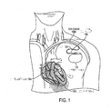
- FIG. 1 illustrates a schematic of one example of a pacemaker implantation.
- a lead 120 has a terminal connector 130c at one end and distal electrodes 130a and 130b at the other end.
- the lead is inserted into the right or left subclavian vein and maneuvered such that distal electrode 130a contacts the atrium wall and/or distal electrode 130b contacts the ventricle wall of the heart.
- the proximal end of the lead (terminal connector) is connected to an energy source that provides electrical energy to the heart, via the lead 120, at a desired rhythm or pattern, which itself undergoes a subcutaneous or submuscular implantation procedure. It should be appreciated that FIG.
- Typical pacing systems may include one, two, three, four or more leads and associated electrodes.
- one electrode may be referred to as the distal electrode and the other the proximal electrode (e.g., the tip and ring electrodes used for bipolar stimulation).
- lead 120 may need to be extracted from the body for any number of reasons. Infection caused by the pacing system (e.g., infection resulting from the implanted leads or the pacing generator pocket) is the leading reason for a physician to determine that, for the patient's safety, the lead(s) should be extracted from the body. In addition, physical damage to the lead may require lead extraction. For example, fracturing of the lead or damage to the insulation surrounding the lead may cause the device to operate non-optimally, to be altogether non-functional and/or present a risk to the patient, and therefore may require the lead to be extracted and optionally replaced.
- Infection caused by the pacing system e.g., infection resulting from the implanted leads or the pacing generator pocket
- the lead(s) should be extracted from the body.
- physical damage to the lead may require lead extraction. For example, fracturing of the lead or damage to the insulation surrounding the lead may cause the device to operate non-optimally, to be altogether non-functional and/or present a
- a lead left in the body from a previously removed device may need to be removed due to interference with a new lead and/or pacing device.
- an abandoned lead may occupy intravenous space preventing a new lead from being inserted, thus requiring the abandoned lead to be removed.
- Lead interaction with the body may also require the lead to be extracted.
- excessive scar tissue at the tip of the lead may render the lead non-functional and/or may require the device to provide more energy than the device was designed to deliver.
- Venous obstruction by the lead causing interruption of the blood flow, interference of the lead with the circulatory system or other implanted devices, and/or pain at the site of implant all may recommend extraction of the lead. Numerous other complications may arise that cause a physician to determine that lead extraction is required for the patient's comfort, safety and/or death. For example, a physician may want to replace a lead from a potentially dangerous recalled device or update an older device with a new device to exploit new technological advances.
- Standard pacemaker leads are formed from a coiled wire having a hollow center (lumen) along the axis of the lead.
- the lead lumen may be used to assist in extracting the lead from the body.
- Such lead extraction devices typically operate by having a guide wire with an outer diameter less than the inner diameter of the lead threaded through the lumen until it reaches the distal end (e.g., the location in which the lead is anchored into the ventricle or atrium wall of the heart).
- the guide wire may be provided with a distal portion that can be expanded to engage and grip the internal wire coil of the lead.
- the distal end of the guide wire may include a coil of wire that can be unwound from the proximal side of the guide wire once the guide wire has reached the distal end (e.g., the implantation end) of the lead. As the wire unwinds, it tangles with the internal wire coil of the lead to anchor the distal end of the guide wire. The guide wire may then be pulled out, extracting the lead along with it.
- lead extraction may be complicated by tissue adhering to the outer surface of the lead.
- scar tissue may form around the lead at any number of different sites (e.g., the insertion point of the lead into the vein or at any location along the vein and/or heart wall) making it difficult for a surgeon to extract the lead without tearing the surrounding tissue.
- the leads can become attached to one another creating a relatively complicated extraction procedure that is often problematic using conventional lead extraction devices.
- Lead extraction devices that utilize the internal lumen of the lead for extraction do not address the problem of fibrous tissue attached to the external portion of the lead and may therefore be rendered ineffective, or are used with significant risk of tearing critical internal blood vessels and causing dangerous, and sometimes fatal, damage to the patient should the lead be extracted using excessive force.
- a knife or edged implement operated by a surgeon and/or utilize laser or diathermic devices that provide laser or electrical energy to cut the surrounding tissue to release the lead for extraction.
- a hollow sheath having a cutting portion on the distal end may be threaded over the lead.
- a surgeon may then manually forced the sheath forward so that the cutting portion engages the attached tissue and cuts the tissue away from the lead.
- the surgeon may also manually rotate the sheath to facilitate cutting and or use a trigger gun that attaches to the sheath and that rotates the sheath when the trigger is engaged.
- laser or diathermic devices are affixed to the cutting portion of the lead to ablate the tissue to assist in separating surrounding tissue from the lead.
- US4576162 describes a lead extracting apparatus.
- the apparatus has a metal cannula which is slipped over the lead to be removed.
- a metal shearing cylinder with a cutting edge is advanced over the surface of the cannula.
- a mechanical locking element is activated to lock the cannula to the lead. Further advancement of the cylinder causes the teeth to separate a thin layer of scar tissue.
- the two-part form of claim 1 is based on this document.
- a device for assisting in removing an implanted lead comprising a body portion having a center adapted to accommodate the lead; a cutting component coupled to the body portion to assist in separating tissue from the lead; and characterised by at least one anchoring component disposed at least partially within the body portion, the at least one anchoring component capable of providing pressure on the lead that resists movement of at least part of the body portion along the lead at least in part by applying fluid pressure, wherein the at least one anchoring component includes at least one anchoring balloon that provides pressure on the lead to resist movement when inflated.
- Some aspects of the invention derive from Applicant's appreciation that utilizing pressure changes to semi-automate or fully-automate at least part of the lead extraction process may result in simpler, safer and more effective lead extraction procedures.
- one or more hydraulic and/or pneumatic techniques may be used to anchor and/or advance a lead extraction device along a lead and/or facilitate separating tissue from the lead or separating two leads from one another.
- anchor or anchoring is used herein to describe the function of applying force/pressure that tends to resist motion of at least one part, portion or component in at least one direction.
- utilizing pressure changes to semi-automate or fully-automate at least part of the lead extraction process may result in simpler, safer and more effective lead extraction procedures.
- one or more hydraulic and/or pneumatic techniques may be used to advance a lead extraction device along a lead.
- fluid pressure changes are used to inflate/deflate one or more balloons, tubes or other components, to anchor and/or advance the device over the lead and/or to cut/separate tissue from the lead.
- inflate describes the operation of increasing fluid pressure
- deflate describes the operation of decreasing fluid pressure.
- the term fluid is used herein to describe gases, liquids and some solids (e.g., foams or other solids that can be used to effect pressure changes).
- anchoring, advancing and cutting is achieved utilizing fluid pressure techniques.
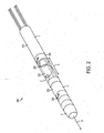
- FIG. 2 illustrates a lead extraction device in accordance with some embodiments of the present invention.
- Device 200 comprises a body 5 having a hollow central axis that is at least wide enough to accommodate a heart lead.
- the body includes a proximal portion 1, an expansion portion 2, a distal portion 3 and a cutting portion 4.
- Cutting portion 4 may be positioned at a distal end of the device (e.g., at one end of distal portion 3) and may be, for example, a circular blade having an opening designed to accommodate a lead and capable of cutting tissue that has grown on the lead as the device is advanced along the lead in the direction indicated by arrow 6.
- cutting portion 4 rotates as the device advances along the lead to facilitate separating the lead from any tissue that has grown on, or otherwise adhered to the lead, and or two separate two leads from one another.
- the blade does not rotate and tissue separation is performed by the cutting portion being advanced along the lead, as discussed in further detail below.
- the cutting portion may rotate and advance simultaneously or rotation and advancement may be two separate and independent motions.
- the rotation of the cutting portion may be in a single direction (e.g., clockwise rotation) or may rotate both clockwise and counterclockwise in alternation.
- the cutting portion may fully rotate or may affect only partial rotation, as the aspects of the invention are not limited for use with any particular cutting mechanism.
- Proximal portion 1 may be located at the opposite end of the device from the cutting blade and may contain one or more anchoring balloons 210 adapted to grip the lead when inflated.
- the anchoring balloon is torus shaped such that when deflated a lead can pass through the center of the torus unimpeded and when inflated the balloon constricts and grips the lead to anchor the device, as discussed in further detail below
- the term "balloon” refers herein to any structure or combination of structures, having one or more portions that vary under fluid pressure.
- a balloon may include structure(s) having one or more portions capable of being inflated and/or deflated using forced fluid (e.g., forced air, liquid or solid such as foam).
- a balloon can be a single component or formed from multiple components depending on what effect is desired upon inflating/deflating the balloon (e.g., elongation, constriction, anchoring, etc.).
- FIGS. 3A and 3B illustrate a cross-section of an anchoring component (e.g., an anchoring balloon) in both the deflated and inflated states, respectively, in accordance with some embodiments of the present invention.
- the anchoring component includes a balloon comprised of an outerl tube 305 formed from a relatively rigid material (e.g., a steel, silicone or polymer tube) and an inner tube formed from a relatively elastic material (e.g., silicone, nylon, polymer or other materials by which medical balloons and/or tubing are formed).
- a relatively rigid material e.g., a steel, silicone or polymer tube
- a relatively elastic material e.g., silicone, nylon, polymer or other materials by which medical balloons and/or tubing are formed.
- a gap 307a may exists between the outer and inner tube whereby the pressure within the gap permits the inner tube to relax such that there is a gap 307b between the inner tube 315 and the lead 375 and/or sufficient space or lack of resistance between inner tube 315 and lead 375 such that the anchoring component is capable of movement along the length of the lead.
- Inflating the anchoring component may include forcing fluid (e.g., air, liquid, etc.) into gap 307a causing increased pressure to be exerted on the inner tube. Because the outer tube is relatively rigid and resistant to expansion, the increased pressure causes the inner tube to depress inwards to grip the lead and fix the anchoring component relative to the lead, as illustrated in FIG. 3B .
- gap 307 expands under the increased pressure caused by fluid inflating pressing the inner tube towards the lead and causing gap 307b to decrease and/or be entirely removed as the inner tube constricts around the lead.
- FIGS. 3C and 3D illustrate a cross-section of an anchoring balloon in both the deflated and inflated stages, respectively, in accordance with alternative embodiments.
- Balloon 310 may be a torus shaped balloon that forms a central hole that, when the balloon is deflated, has a diameter that can accommodate the heart lead and allow relative movement between the lead and the balloon.
- balloon 310 is deflated and lead 375 passes through the center of the balloon relatively unimpeded as the inner wall of the balloon does not grip lead, thus allowing the balloon to slide up or down the lead.
- balloon 310 has been inflated such that the inner wall of the balloon grips the lead and the friction therebetween prevents motion of the balloon relative to the lead.
- inflation causes fluid to fill the balloon, simultaneously reducing the size of the center hole until the inner wall grips the lead.
- the anchoring balloons need not be designed to accommodate the lead through a center of the balloon.
- a balloon may be disposed over, under or to the side of a lead such that when the balloon is inflated, the balloon applies pressure to the lead such that the balloon resists relative movement between the lead and some portion of the lead extraction device.
- the expansion of balloon 310 in an outward direction may be substantially prevented, for example, by providing the balloon inside a relatively rigid tube (e.g., the body or outer tube of the lead extraction device) such that expansion of the balloon outward is prevented and inflation results primarily or substantially in inward constriction of the center hole.
- the relatively rigid tube may be formed from any material such as metal, plastic, polymer, silicone or any other suitable material. Outward expansion of the balloon may be prevented in other ways, as the aspects of the invention are not limited in this respect.
- FIGS. 3C and 3D are toroidal in shape, it should be appreciated that the anchoring balloon may be of any shape capable of gripping and releasing a lead. Other methods of achieving anchoring using pressure changes may be used as well, as the aspects of the invention are not limited in this respect. It should be appreciated that the cross-sections of the anchoring balloons in FIGS. 3A-3D are merely schematic to illustrate principles of anchoring via balloon inflation. The dimensions illustrated are not meant to depict actual absolute or relative dimensions.
- expansion portion 2 includes a spring mechanism 225 and an elongation component 220 (e.g., one or more elongation balloons).
- Spring mechanism 225 connects the proximal portion with the distal portion and an elongation balloon 220 is arranged to stretch the spring when inflated and allow the spring to return to repose when deflated.
- the elongation component may be formed from and inner tube and an outer tube, both of which may be relatively flexible. The inner tube and the outer tube may be connected to each other at each end (e.g., at the end where the expansion portion connects to the proximal portion and at the end where the expansion portion connects to the distal portion).
- Spring mechanism 225 may be any type of component such as a standard spring or an accordion type material that can be elongated under fluid pressure.
- Distal portion 3 may include one or more distal anchoring balloons (or any other type of anchoring mechanism) arranged to grip the lead at the distal end of the device.
- the one or more distal anchoring balloons may be similar in construction and operation to the anchoring balloons described in connection with FIGS. 3A-3D , or may be any other type of component capable of gripping and releasing the lead under fluid pressure as desired, as the aspects of the invention are not limited in this respect.
- Device 200 may also include a rotation component 234 coupled to the cutting portion to cause the cutting portion to rotate as the device advance forward along the lead.
- rotation component 234 has a member on both the proximal and distal end of the device to effect rotation and may use a slot and pin mechanism, as discussed in further detail below.
- Other types of rotation mechanisms may also be used (some embodiments of which are also discussed below), as the aspects of the invention are not limited for use with any particular type of rotation component.
- FIGS. 4A-4F illustrates the internal components of a lead extraction device (e.g., the internal components of lead extraction device 200 illustrated in FIG. 2 ) at each of a number of stages of an extraction operation cycle that advances the device over the lead and separates the lead from any attached tissue that may prevent the removal of the lead, according to some embodiments.
- device 400 includes a proximal anchor balloon 410, an expansion balloon 420, a distal anchoring balloon 430 and a spring 425 that connects the distal and proximal portions of the device.
- Device 400 is shown inserted over a lead 495, for example, by a surgeon that threads the exposed end of the lead through the central axis of the sheath.
- FIG. 4A illustrates a first stage of an operation cycle of the lead extraction device after the device has been placed on the lead.
- all of the balloons may be deflated.
- anchoring balloons 410 and 430 are deflated such that the device is free to slide along the lead (i.e., the lead can pass through the center of the sheath relatively unimpeded by either anchoring balloons.
- This stage allows the surgeon to thread the lead through the center of the sheath and position the device for extraction of the lead.
- the expansion balloon 420 may also be deflated such that spring 425 is in repose and the distal and proximal portion are as close together as the spring will allow. From this stage, the device is ready to begin extracting the lead.
- FIG. 4B illustrates a second stage of the operation cycle of the lead extraction device.
- the proximal anchoring balloon 410 is inflated such that the balloon grips the lead and anchors the proximal portion of the device such that motion of the proximal portion relative to the lead is prevented.
- the proximal anchoring balloon 410 may transition from deflated (e.g., as shown in FIG. 3A ) to inflated (e.g., as shown in FIG. 3B ) such that the inner tube is pressed inward to grip the lead.
- proximal anchoring balloon 410 may be implemented as the torus shaped balloon described in connection with FIGS. 3C and 3D , such that inflation causes the center hole to constrict around the threaded lead.
- FIG. 4C illustrates a third stage of the operation cycle that advances the distal portion of the device forward along the lead, separating tissue that may be attached to the lead.
- the elongation balloon 420 is inflated to stretch spring 425. Since the proximal portion of the device is anchored by inflated anchoring balloon 410, the spring forces the distal portion forward along the lead as the spring is stretched by elongation balloon 420. The forward force on the distal portion causes the cutting portion to advance along the lead and cut tissue attached to the lead to prepare the lead for extraction. In some embodiments, the forward force also rotates the cutting portion to facilitate separating the tissue from the lead, as discussed in further detail below.
- FIG. 4D illustrates a fourth stage of the operation cycle that anchors the distal portion of the device to the lead.
- the distal anchoring balloon 430 may be inflated to grip the lead.
- Anchoring balloon 430 may operate in a same or similar manner as the proximal balloon 410 describe above.
- both the proximal and distal portions of the device are anchored to the lead and the spring 425 is stretched by the inflated elongation balloon 420.
- anchoring balloon 430 may include an inflation tube or other inflation mechanism, although no such mechanism is illustrated in FIGS. 4A-4F .
- anchoring balloon 430 may be replaced with an anchoring component that applies a substantially constant resistance to movement relative to the lead such that inflation/deflation of the distal anchoring component is not necessary, some embodiments of the which are discussed in further detail below.
- FIG. 4E illustrates a fifth stage of the operation cycle wherein the elongation balloon 420 is deflated causing the spring 425 to tend to relax back to repose.
- proximal anchoring balloon 410 is also deflated. Because the distal anchoring balloon 430 is inflated, the force of the contracting spring as it returns to repose pulls the proximal portion of the device (now released due to the deflation of the proximal anchoring balloon 410) forwards to advance the proximal portion of the device along the lead. The distal anchoring balloon may then be deflated to return the device to the first stage.
- all balloons may be deflated and the device returns to its initial configuration but has been advanced along the lead, separating (or at least partially cutting/separating) tissue that the cutting portion may have encountered during the incremental advancement of the operation cycle (see e.g., FIG. 4F ).
- the stages may be repeated to continue to advance the device forward until the device has advanced as far as it needs to advanced in order to release the lead so that it can be pulled from the body. It should be appreciated that the various stages need not be performed sequentially and portions of the stages or entire stages may be performed simultaneously and/or may overlap in time, as the aspects of the invention are not limited for use with any particular timing scheme.
- the lead extraction devices described above embody a number of general concepts that facilitate advancing a lead extraction device along a lead while separating tissue that has attached to the lead and/or separating the lead from another lead to which is has adhered.
- the lead extraction devices describe above illustrate examples of how a lead extraction device can be internally advanced using applied pressure changes, including using applied pressure changes to anchor, advance and/or cut.
- anchoring, advancing and cutting can be implemented in a variety of different ways, some embodiments of which are described in further detail below. It should be further appreciated that implementations embodying the concepts of anchoring, advancing and cutting may be used alone or in any combination, as the aspects of the invention are not limited to the specific combinations specifically illustrated herein.
- the distal anchoring component is formed from a constant friction component, rather than an inflatable/deflatable anchoring component (e.g., the inflatable/deflatable anchoring balloons illustrated in FIGS. 3A-3D ).
- the distal anchoring component may provide a constant friction to the lead that is greater than the resistance of the proximal anchoring component on the lead when it is not engaged (e.g., deflated) and less than the resistance of proximal anchoring component on the lead when it is engaged (e.g., when inflated), as discussed in further detail below.
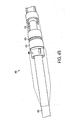
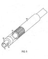
- FIG. 5 illustrates a distal anchoring component having a constant friction portion, in accordance with some embodiments of the present invention.
- Proximal anchoring component may be any of the anchoring components described herein capable of anchoring and releasing a lead as desired due to fluid pressure changes.
- expansion component 520 may include any of the mechanisms described above for elongating the distance between the proximal and distal portions of the lead extraction device (e.g., one or more elongation balloons).
- Distal anchoring component 530 may be a constant friction component that applies a substantially constant friction on the lead.
- Distal anchoring component 530 may be a relatively rigid tube having a portion that is bent inwards to contact the lead to apply a constant friction.
- the rigid tube may have one or more perforated tabs 532 that can be pressed inward to pinch the lead to provide a desired resistance against motion along the lead.
- the constant friction component may be formed by twisting a spring that contacts the lead at desired locations and pressure to apply a substantially constant friction to the lead.
- the distal anchoring component may have a substantially constant resistance that is greater than the resistance of the proximal anchoring component when the proximal anchoring component is not engaged and less than the resistance of the proximal anchoring component when the proximal anchoring component is engaged.
- the constant friction component provides greater resistance against movement such that as the spring mechanism returns to repose, the proximal portion (disengaged) is pulled towards the distal portion to advance the device along the lead.
- a purpose of some embodiments of a lead extraction device is to separate tissue that has grown on or attached itself to the lead to facilitate lead removal without unnecessarily tearing and/or damaging the surrounding tissue.
- separation may be performed by providing a cutting portion (e.g., a knife or blade) having one or more edges designed to cut tissue to help in separating tissue from the lead.
- the forward motion of the lead extraction device provides the force to separate tissue from the lead.
- the cutting capabilities of the lead extraction device may be improved by adding rotation in addition to forward motion. A number of non-limiting embodiments of rotating cutting portions are described in further detail below.
- FIGS. 6A and 6B illustrate a slot and pin mechanism that allows for rotations of the cutting portion during operation.
- FIG. 6A illustrates a lead extraction device have a cutting portion coupled to a rotation mechanism that causes the cutting portion to rotate during advancement of the distal end of the device, in accordance with some embodiments.
- FIGS. 6A and 6B components involved in rotation are illustrated while other components of the device may be omitted in the drawing, though discussed in the description.
- the portion of the device includes a relatively rigid tube 601, a cutting portion 640 and a rotation component including a member 634, member 644, pin 631, axial slot 632 and diagonal slot 633.
- Member 634 is coupled to the distal portion of the device and is forced forward when the device is elongated (e.g., upon inflation of one or more elongation balloons) and pin 631 is attached to member 634.
- Member 644 is coupled to the cutting portion and includes diagonal slot 633. As member 634 is advanced forward, the pin presses against the diagonal slot causing member 644 to rotate and advance, thus causing the cutting portion to simultaneously rotate and advance to cut incident tissue during the elongation phase of the lead extraction device.
- the pin and slot mechanism may be implemented in other ways, as the aspects of the invention are not limited in this respect.
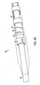
- FIGS. 7A and 7B illustrate a lead extraction device having a cutting portion coupled to a rotation mechanism, in accordance with some embodiments of the present invention.
- the premise behind the operation of the rotation mechanism in FIG. 7 involves the interlocking of reciprocal components, for example, interlocking teeth, prongs or other cooperating structures that can be engaged.
- FIG. 7 components involved in rotating the device are illustrated while other components may be omitted.
- the lead extraction device includes a relatively rigid tube 708, a portion of which may form the outer diameter of a proximal anchoring balloon.
- a rotation component is comprised of two cooperating rotating members 770 and 780, each having reciprocal teeth that correspond to one another and engage when brought together.
- Member 724 moves with the distal portion of the device and is attached to one side of member 770. Accordingly, when member 724 is forced forward (e.g., by inflation of an elongation balloon), member 770 is also moved forward to engage with member 780 as illustrated in FIG. 7B .
- Member 780 is in turn coupled to the cutting portion 740. Once members 770 and 780 engage, the cutting portion will rotate as member 770 is force forward and rotates do the elongation operation of the device. When the elongation component contracts, the members 770 and 780 disengage and return to the position illustrated in FIG. 7A . Thus, the cutting portion is rotated during the elongation stage of the operation cycle only.
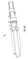
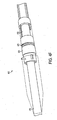
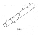
- FIG. 8 illustrates the front portion of a lead extraction device having a cutting portion coupled to a rotation component, in accordance with some embodiments.of the present invention. As discussed above, components effecting a rotation of the cutting portion are illustrated while other components may be omitted.
- the lead extraction device in FIG. 8 is designed with a rotation component capable of rotating the cutting portion both during elongation (e.g., advancement of the distal portion) and during contraction (e.g., advancement of the proximal portion).
- the rotation component includes three rotation members 870, 880 and 890. Rotation members 870 and 880 may be similar in principle and operation to the coopering rotating members 770 and 780 described above in connection with FIGS.
- rotating member 870 when rotating member 870 is forced forward and rotates, it rotates the cutting portion 840 when it engages with rotating member 880 to effect a forward advancement and rotation of the cutting portion during forward advancement of the distal portion (e.g., during an elongation phase).
- rotating member 880 includes teeth structures to engage with both the rotating member 870 and rotating member 890, the latter of which effects rotation of the cutting portion during the advancement of the proximal portion of the device (e.g., during a contracting phase).
- Rotating member 890 may be slid over the cutting portion and forced to move in the same direction as rotating member 870. When the expansion portion of the device is elongated, rotating member 870, and thus rotating member 890, are forced towards the distal end of the device.
- rotating member 870 engages rotating member 880 to advance and rotate the cutting portion as the expansion portion is elongated.
- the rotating member 870 moves back towards the proximal end, forcing rotating member 890 in the same direction.
- rotating member 880 remains static in the absence of forces from the other rotating members, rotating member 890 engages with and rotates rotating member 880 as it moves towards the proximal end.
- the rotation of rotating member 880 causes the cutting portion to rotate both in the elongation and contraction stages (e.g., both when the distal portion advances along the lead and when the proximal portion advances along the lead).
- FIG. 9 illustrates inflating balloons via tubes, in accordance with some embodiments of the present invention.
- a tube 905 is coupled to proximal anchoring balloon 910 such that fluid may be forced into the proximal anchoring balloon to inflate the balloon to grip the lead.
- tube 915 is coupled to elongation balloon 920 such that fluid may be forced into the balloon to elongate the balloon and stretch the spring mechanism.
- a third tube may be implemented to inflate the distal anchoring balloon in the same manner.
- the tubes may be of any type capable of providing fluid to the respective balloons (e.g., air, liquid or a solid such as foam).
- the tube may have an accordion shape and/or be capable of being stretched.
- the cross-section of the inflation tubes are shown as circular, the cross-section may be of any shape (e.g., elliptical), as the aspects of the invention are not limited in this respect.
- inflation may be achieved by annular tubes concentrically arranged about each of the respective components being inflated, as discussed in further detail below.
- the inflation tubes may be coupled to a respective pump mechanism that allows fluid to be pumped into the device (e.g., into the respective balloon).
- the pump mechanism may be a syringe with a spring and by pressing the syringe handle or plunger forces air/fluid into the balloons.
- the fluid is a liquid (e.g., water, saline or some other desired solution), thus utilizing hydraulics to operate the lead extraction device.
- the fluid is a gas (e.g., compressed air or some other gas such as an inactive or inert gas), thus utilizing pneumatics to operate the lead extraction device.
- a combination of hydraulic and pneumatic techniques may be used to operate the lead extraction device, as the aspects of the invention are not limited in this respect.
- the pump mechanism may be a squeeze pump that can be manually squeezed to fluid into the balloons (e.g., similar to squeeze balls commonly used to inflate blood pressure arm bands).
- the squeeze pump may include a release valve to release the pressure for deflation.
- Any of the various suitable pump mechanisms may be connected to a motor to inflate the respective balloons.
- the pump mechanism may be part of a compressor unit capable of producing forced fluid.
- fluid may be delivered to the device via one or more annular tubes provided concentrically around the balloons.
- the balloons may be inflated/deflated by any other suitable means, as the aspects of the invention are not limited to any particular method by which balloons are inflated/deflated.
- FIG. 10 illustrates a portion of a lead extraction device capable of operating without the use of a spring, in accordance with some embodiments of the present invention.
- the advancement of the lead extraction device in FIG. 10 may be powered by a mechanism capable of achieving sufficient forces both when inflating and deflating an elongation balloon.
- balloons may be inflated and/or deflated via tubes.
- a proximal anchoring balloon 1010 is inflated and/or deflated via inflation tube 1005 and elongation balloon 1020 is inflated and/or deflated via inflation tube 1015.
- the proximal anchoring balloon and elongation balloon may operate in a manner similar to any of the mechanisms described herein.
- Elongation balloon 1020 pushes part 1034 of the distal portion forward and rotates (via the rotation mechanism 1075) the knife to advance the distal portion of the device forward.
- a contracting balloon 1060 may be provided to perform substantially the same function.
- the energy stored in a stretched spring is replaced by energy stored in an inflated contracting balloon 1060. That is, after elongation and while elongation balloon 1020 is still inflated, the contracting balloon 1060 may be inflated to resist the distal portion and the proximal portion from coming together (e.g., similar to the resistance proffered by a stretched spring).
- the elongation balloon and the distal anchoring balloon may be deflated. The subsequent deflating of the contracting balloon releases the resistance and pulls the proximal portion towards the distal portion to complete the advancement of the device.
- some conventional lead extraction devices require the physician/surgeon to fully operate the device manually.
- This process may include manually securing one end of the lead (e.g., the portion protruding from the body and/or the portion that has been already extracted) while manually forcing the device forward to cut any connected tissue (e.g., by forcing forward a sheath having a knife on the distal end to engage with tissue interfering with the removal of the lead).
- This process can be very awkward for the surgeon and may be prone to error.
- various concepts described herein may be used alone or in different combinations to provide improvements to the fully manual lead extraction device.
- Several examples of lead extraction devices using anchoring concepts are described in further detail below.
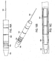
- FIG. 11A illustrates a portion of a lead extraction device that uses internal anchoring to assist in lead extraction, in accordance with some embodiments of the invention.
- FIG. 11B illustrates a cross-section of the portion of the lead extraction device illustrated in FIG. 11A .
- an anchoring balloon 1130 is provided on a distal end of a lead extraction device.
- some conventional techniques for lead extraction involve threading a sheath having a distal cutting portion over the lead and manually forcing the sheath against obstructing tissue and/or twisting the sheath to facilitate cutting of the surrounding tissue.
- One or more anchoring balloons added to the distal end of such a device may facilitate separating the lead from the surrounding tissue.
- Sheath 1101 may be a conventional sheath or any type of sheath capable of being threaded over the lead.
- the sheath has a relatively low rigidity for bending, but relatively high rigidity with respect to buckling and twisting.
- any suitable sheath may be used, as the aspect of the invention are not limited for use with any particular type of sheath or outer shell/body.
- the sheath may include a cutting portion on the distal end or may be provided without a cutting portion.
- One or more anchoring balloons may be provided at the distal end of the sheath.
- an anchoring balloon 1130 of the type discussed herein may be provided such that the sheath can be anchored to and released from the lead as desired.
- a surgeon may thread the sheath over the lead and push the device until it reaches attached tissue.
- the surgeon may then inflate anchoring balloon 1130 via inflation tube 1135 to anchor the device to the lead.
- the surgeon may pull on the device to release the lead from the attached tissue.
- the surgeon may also effect a twisting motion to assist in releasing the lead from the surrounding tissue. It should be appreciated that the surgeon may grip, pull and/or twist the device manually or may use other devices to assist and facilitate this motion, as the aspects of the invention are not limited in this respect.
- an anchored wire guide device may be pulled while the device is being pushed forward to the tissue and/or during the interval when the surgeon pulls/twists the anchored lead extraction device.
- one or more proximal anchoring balloons may be used to facilitate extraction of a lead from a body.
- the balloon illustrated in FIGS. 11A and 11B may be provided on the proximal side of the lead extraction device to assist in anchoring the device as a surgeon forces a connected distal portion forward along the lead.
- the lead extraction device may have a distal portion that can be advanced independently of the proximal portion, such as a device that has an inner and an outer sheath, the outer sheath having a cutting portion that a surgeon can manually push forward to separate tissue from the lead.
- the surgeon can position the device as desired and anchor the lead extraction device so that the surgeon does not have to both manually anchor the device and force forward the distal portion. Instead, the surgeon can focus on cutting the tissue at the distal end without having to worry about the proximal end of the device moving relative to the lead. This may result in freeing up one of the surgeons hand and decreasing the difficulty of the procedure.
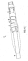
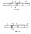
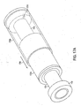
- FIGS. 12A and 12B illustrate a lead extraction device having an extension portion formed from a relatively rigid outer tube and a flexible internal elongation tube.
- the relatively rigid outer tube may allow increased pressure upon inflation, thus increasing the force with which the cutting portion can be advanced/rotated along the lead, thereby improving the cutting ability of the device.
- the lead extraction device illustrated in FIGS. 12A and 12B may include a cutting portion 1240, an expansion portion 1220 and a proximal portion 1210.
- the proximal portion 1210 may include one or more anchoring components of any type or combination of types described herein.
- cutting portion may include any type of knife and may be provided with or without one or more rotating components described herein.
- the expansion portion may be improved by providing both an outer tube 1222 that is relatively rigid (e.g., a steel or plastic tube) and an inner flexible elongation tube 1224.
- a seal 1226 may be provided between the cavity enclosing the expansion portion and the cavity enclosing the proximal anchoring component to prevent leakage from the elongation cavity to the anchoring cavity even under relatively high pressure.
- the seal may be of a conical shape and made of a relatively soft material such that when the inner elongation balloon is inflated, the fluid pushes the seal to against the outer tube, preventing leakage into the anchoring cavity (e.g., possible leakage in and around the inflation tube 1215).
- the seal may be arranged to prevent leakage external to the device.
- the portion of component 1220 that slides over component 1210 is extended and a gap may form between the two components.
- the seal may be arranged to prevent fluid leakage outside the device via the gap under such circumstances.
- the rigid outer tube prevents expansion of the elongation tube outward such that inflation pressure provides increased force in the longitudinal direction.
- the increased pressure that can be used to inflate the elongation balloon e.g., due to the outer rigid tube and/or the seal
- Other sealing mechanisms can be used to increase the pressure capacity of the device, as the aspects of the invention are not limited in this respect.
- Some aspects of the invention include using fluid pressure changes to anchor and advance/rotate a lead extraction device.
- some embodiments include one or more anchoring balloons (e.g., proximal and/or distal anchoring balloons) and one or more elongation balloons.
- fluid pressure changes can be used to both anchor and advance/rotate a lead extraction using balloons that perform both anchoring and forward motion functions.
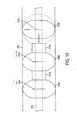
- FIG. 13 is a schematic representation illustrating the principle of using a chain of balloons that each operate as both anchoring and elongation balloons.
- FIG. 13 illustrates a portion of a lead extraction device having an outer tube 1301 formed from a relatively rigid material that substantially prevents balloons from inflating outwards.
- the portion of the device also includes a chain of three balloons 1310a-1310c, with balloon 1310a on the proximal side of the chain and balloon 1310c on the distal side of the chain.
- the balloons may be toroidal in shape or any shape having a center hole through which lead 1375 may be threaded.
- Balloons 1310 are connected via a connector 1317 that may include a relatively short length of pipe/tube and/or a valve that prevents fluid from flowing from one balloon to another until a desired pressure differential between the balloons is achieved.
- the balloons are illustrated in solid lines in the deflated state. The dotted line denotes the result of inflating balloon 1310a.
- the inside diameters 1311 of the deflated balloons are wider than the diameter of the lead so that the balloons can move relative to the lead.
- balloon 1310a When balloon 1310a is inflated (e.g., via an inflation tube), the balloon expands in the two directions indicated by the arrows. Specifically, the balloon expands such that the center hole constricts and grips the lead (as shown by the reduced inner diameter 1311a of balloon 1310a) and the balloon expands along the lead as indicated by the dotted lines.
- the outer tube prevents the balloon from expanding outwards.
- the expansion of balloon 1310a along the lead forces the adjacent balloon 1310b to advance along the lead. Fluid may be continually forced into balloon 1310a.
- the pressure differential between balloon 1310a and balloon 1310b reaches a threshold value determined by the pipe and/or valve, fluid is forced into balloon 1310b and the balloon begins to inflate.
- balloon 1310b begins to inflate to both anchor the balloon to the lead and force adjacent balloon 1310c to advance along the lead. Because balloon 1310a is anchored to the lead, the expansion of balloon 1310b does not effect the location of balloon 1310a with respect to the lead. When the pressure differential between balloons 1310b and 1310c reaches a threshold, balloon 1310c begins to inflate. When all three balloons are inflated, each balloon is anchored to the lead and the distal end of the chain has been advanced along the lead (e.g., by the sum of the incremental advancements of each balloon in the chain). It should be appreciated that the last balloon on the distal end of the chain can be coupled to a cutting portion and/or rotation component such that the expansion of the chain forces the cutting portion forward and/or rotates the cutting portion to separate incident tissue.
- the balloons are iteratively deflated from the proximal end to the distal end in a similar manner.
- balloon 1310a may first be deflated, releasing the lead as the inner diameter returns to its deflated dimensions. Because balloon 1310b is still anchored to the lead, the connection between balloons 1310a and 1310b causes balloon 1310a to be drawn towards balloon 1310b to advance the balloon along the lead. When the pressure differential between balloons 1310b and 1310a reaches a threshold value, balloon 1310b begins to deflate, releasing the balloons hold on the lead.
- FIG. 13 is schematic to illustrate the principle and relative dimensions may not be accurate as certain components are enlarged to better illustrate the underlying concepts.
- any number of balloons may be used to form the chain adapted to both anchor and advance a lead extraction device along the lead, as the aspects of the invention are not limited for use with any particular number of balloons.
- the linking component between the balloons may be any type of component that connects the balloons and allows fluid under pressure to pass between the balloons (e.g., that prevents fluid exchange until a desired pressure differential between adjacent balloons is reached and/or exceeded).
- the balloons in the chain can be formed from round torus shapes, cylindrical shapes or any other suitable shape that performs anchoring and advancement during an inflation/deflation cycle, as the aspects of the invention are not limited for use with balloons of any particular shape.
- typical heart leads cover the inner wire (or wire coil) with a dielectric material.
- This material is often made from silicone or a polyurethane material.
- Materials used for constructing balloons may also be made from the same or similar materials. Accordingly, a problem may arise that when a balloon is in the deflated state, while not gripping the lead, the inner circumference may rest against and/or contact the lead. As a result, some amount of friction remains between the inner circumference of the balloon and the lead. Depending on the extent of this friction, proper advancement of the balloons may be partially or entirely impeded, frustrating advancement of the device.
- Rings inserted within the inner circumference of the balloon that have some spring resistance outward to force the inner circumference of the balloon away from the lead may be provided to prevent the inner circumferences of the balloon from providing drag on the lead when deflated, as discussed in further detail below.
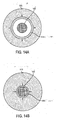
- FIG. 14 illustrates a cross-section of a balloon having a ring 1414 affixed to the inner circumference of balloon 1410.
- Ring 1414 may be formed from an elastic material that in the absence of other greater forces, returns to a resting state wherein the diameter of the ring is as shown in FIG. 14A .
- the ring may be collapsible when an outside force is applied that is greater than the ring's natural tendency to conform to the shape illustrated in FIG. 14A .
- the natural tendency of the ring to return to its maximum diameter forces the balloon 1410 away from the lead such that the balloon has little or no contact with the lead, allowing the balloon to move relative to the lead with relative freedom.
- ring 1414 may be formed from any suitable material that tends to a maximum diameter but whose diameter can be collapsed upon application of the force of an inflating balloon, as the aspects of the invention are not limited for use with rings of any particular material.
- stents may be used in place of the rings.
- a mesh stent may be disposed proximate the inner wall of the balloon such that when the balloon is deflated, the stent forces the balloon away from the lead.
- Other methods of forcing the balloon away from the lead when deflated may also be used, as the aspects of the invention are not limited in this respect.
- FIGS. 15A, 15B and 15C illustrate different views of a chain of balloons capable of both anchoring and advancing a lead extraction device.
- the chain of balloons may operate using the same or similar principle to that described in connection with FIG. 13 .
- balloons 1510 are cylindrical in shape, each connected to the adjacent balloon by a connector 1517 and inflated using inflation tube 1505.
- the connectors 1517 may include a valve that allows fluid to flow to adjacent balloons once a pressure differential between the adjacent balloons has been achieved. It should be appreciated that the dimensions and specific implementation illustrated in FIG. 15 is merely exemplary, and other dimensions, implementations and components may be used, as the aspects of the invention are not limited in this respect.
- the principle of using the same balloons for anchoring and advancing a lead extraction device is incorporated into a single balloon.
- a single cylindrical balloon may be used wherein the connectors are rings that are slid over the balloon and pinched to a desired diameter to create a "neck" between the segments of the balloon.
- component 1500 may be formed from a single cylindrical balloon.
- Connectors 1517 may be rings inserted over the balloon that pinch the balloon into segments 1510a-1510c. The resulting neck therefore provides the "valve" mechanism that permits fluid flow between the balloons only when a desired pressure differential has been achieved between the balloons.
- Other implementations that use the principle of balloons or balloon segments that both anchor and advance a lead extraction device may be used, as the aspects of the invention are not limited in this respect.
- FIGS. 16A, 16B and 16C illustrate views of a lead extraction device incorporating at least some of the anchoring/advancing techniques discussed above in connections with FIGS. 13-15 .
- component 1510 may be a chain of balloons or a chain of segments of a single balloon capable of both anchoring and advancing the lead extraction device. Any of the techniques described herein may be used to implement component 1510.
- component 1510 is coupled to a rotating component 1634 which is in turn coupled to cutting portion 1640. As component 1510 causes advancement, the rotation component 1634 is engaged and causes the cutting portion to rotate and advance to partially or completely separate tissue from the lead.
- Rotation component 1634 may be the same or similar to any of the rotation components described herein or may be implemented in a different suitable manner, as the aspects of the invention are not limited in this respect.
- cutting portion 1640 may be any suitable component adapted to cut through tissue, in addition to a cutting portion adapted with heat, laser and/or RF technology to soften/ablate tissue to facilitate cutting, as the aspects of the invention are not limited in this respect.
- the lead extraction device in FIG. 16 is illustrated as being inflated/deflated via inflation tube 1605, however, any inflation/deflation mechanism may be used.
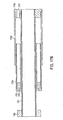
- FIG. 17A illustrates a expansion component for use with a lead extraction device, in accordance with some embodiments of the present invention.
- the expansion component uses a piston mechanism that may be either hydraulically or pneumatically operated to elongate a portion of the device to facilitate advancing the device along the lead.
- the expansion component may include a piston mechanism 1720, an inner tube 1724 and an end portion 1726.
- the piston mechanism 1720 may comprise inner part 1720a and outer part 1720b.
- the inner part 1720a may be moveably coupled to the outer part 1720b such that the inner part 1720a is capable of sliding into and out of outer part 1720b.
- Fluid pressure may be applied to the piston mechanism via hole 1715, which may in turn be connected to an inflation tube.
- the inner part 1720a When fluid pressure is applied to the piston mechanism 1720, the inner part 1720a is forced out of outer part 1720b in the direction of arrow 1706.
- the inner part 1720a may be coupled to a cutting portion or a distal portion coupled to the cutting portion such that when the piston mechanism is inflated, the cutting portion is advanced forward.
- inner part 1720a may be coupled to a rotation component such that when the piston mechanism is inflated, the rotation component causes the cutting portion to rotate simultaneously with or independent from the forward motion of the cutting portion.
- the piston mechanism may be coupled to a spring mechanism such that when the piston mechanism is inflated, the spring mechanism is stretched. When the piston mechanism is deflated, the spring may recoil back to the repose position. The force of the spring mechanism returning to repose may force the inner part 1720a back into outer part 1720b (e.g., by pulling outer part 1720b forward).
- the inner tube 1724 may be a substantially rigid tube that accommodates the lead through the expansion portion. End portion 1726 may be arranged to stop the advancement of the inner part 1720a under fluid pressure. It should be appreciated that the expansion component may be used alone or with any one or combination of the other components described herein to facilitate advancement of a lead extraction device along the lead. Other piston mechanisms that elongate via fluid pressure may be used, as the aspects of the invention are not limited for use with any particular type of piston mechanism.
- FIG. 17B illustrates a cross-section of the expansion portion illustrated in FIG. 17A , showing parts 1722 and 1723 that allow the inner part 1720a to slide out under fluid pressure.
- part 1720c illustrates an end piece 1720c through which inflation tube can be inserted to inflate the piston mechanism.
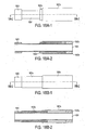
- FIGS. 18A and 18B illustrate a expansion portion for a lead extraction device in a deflated state (both a normal view and a cross-section view) and in an inflated state (both a normal view and a cross-section view), respectively.
- the expansion portion includes a piston mechanism 1820 that may comprise an inner part 1820a, an outer part 1820b and an end piece 1820c.
- the piston mechanism may operate in a manner similar or different than the piston mechanism described in connection with FIGS. 17A and 17B , as long as the inner part 1820a can be extended upon application of fluid pressure.
- FIG. 18A when the expansion component is in the deflated state, the inner part 1820a is substantially within outer part 1820b.
- fluid pressure inflates the piston mechanism as shown in FIG. 18B , inner part 1820a is forced outwards along the lead.
- Other parts, components and mechanism may be included in the expansion portion, as the aspects of the invention are no limited in this respect.
Claims (12)
- Appareil (200 ;400) visant à aider à extraire un fil implanté, ledit appareil comprenant :une partie corps (5 ;601 ;708 ;1101 ;1301) ayant un centre adapté de manière à recevoir le fil ;un élément de coupe (4 ;640 ;1240 ;1640 ;740 ;840) accouplé à la partie corps en vue d'aider à séparer les tissus du fil ; etau moins un élément d'ancrage (210 ;310 ;410 ;430 ;1310 ;1410 ;1510 ;910 ;1010 ;1130) disposé au moins en partie à l'intérieur de la partie corps, caractérisé en ce que le au moins un élément d'ancrage est capable de faire pression sur le fil qui résiste au mouvement d'au moins une section de la partie corps le long du fil au moins en partie en appliquant une pression par fluide,dans lequel le au moins un élément d'ancrage comprend au moins un ballonnet d'ancrage (210 ;310 ;410 ;430 ;1310 ;1410 ;1510 ;910 ;1010 ;1130) qui fait pression sur le fil en vue de résister au mouvement lorsqu'il est gonflé.
- Appareil selon la revendication 1, dans lequel la partie corps possède une partie distale (3) et une partie proximale (1 ;1210).
- Appareil selon la revendication 2, dans lequel le au moins un élément d'ancrage comprend un élément d'ancrage distal capable d'ancrer la partie distale au fil.
- Appareil selon la revendication 2, comprenant, en outre, au moins un élément détendeur (2 ;220 ;420 ;520 ;920 ;1020 ;1220 ;1720 ;1820) capable de modifier la distance entre la partie distale et la partie proximale au moins en partie en appliquant une pression par fluide.
- Appareil selon la revendication 4, dans lequel l'élément détendeur comprend au moins un ballonnet d'allongement (220 ;420 ;920 ;1020) capable d'augmenter la distance entre la partie distale et la partie proximale lorsqu'il est gonflé et/ou comprend un mécanisme à piston (1720 ;1820) fonctionnant sous pression par fluide.
- Appareil selon la revendication 5, dans lequel l'élément détendeur comprend un mécanisme à ressort (225 ;425) reliant la partie distale à la partie proximale, et dans lequel le mécanisme à ressort est étiré quand le au moins un ballonnet d'allongement est gonflé.
- Appareil selon la revendication 4, dans lequel le au moins un élément d'ancrage comprend un élément d'ancrage proximal (210 ;310 ;410 ;910 ;1010 ;1310 ;1410 ;1510) capable d'ancrer la partie proximale au fil.
- Appareil selon la revendication 7, comprenant, en outre, un élément d'ancrage distal (430 ;530 ;1130) qui fait pression sur le fil qui résiste au mouvement de la partie distale le long du fil.
- Appareil selon la revendication 4, dans lequel l'élément d'allongement est capable de forcer la partie distale en avant le long du fil, et dans lequel l'élément de coupe est accouplé à la partie distale de manière à ce que l'élément de coupe soit forcé en avant le long du fil par l'élément d'allongement.
- Appareil selon la revendication 9, comprenant, en outre, un élément de rotatif (234 ;634 ;644 ;631 ;632 ;633 ;770 ;780 ;870 ;880 ;890 ;1075 ;1634) accouplé à l'élément de coupe, l'élément rotatif étant capable de faire tourner la partie de coupe quand la partie distale est forcée en avant le long du fil.
- Appareil selon la revendication 1, dans lequel le au moins un élément d'ancrage comprend au moins un élément détendeur, le au moins élément détendeur étant capable de faire avancer au moins une certaine section de la partie corps le long du fil au moins en partie en appliquant une pression par fluide.
- Appareil selon la revendication 11, dans lequel le au moins un élément d'ancrage et le au moins un élément détendeur sont formés à partir d'une pluralité de ballonnets reliés, chacun des ballonnets reliés de la pluralité étant, lors du gonflement, capable de faire pression sur le fil qui résiste au mouvement d'au moins une section de la partie corps le long du fil et fait avancer au moins une section de la partie corps le long du fil.
Applications Claiming Priority (2)
| Application Number | Priority Date | Filing Date | Title |
|---|---|---|---|
| US14417609P | 2009-01-13 | 2009-01-13 | |
| PCT/IB2010/000206 WO2010082139A1 (fr) | 2009-01-13 | 2010-01-13 | Procédés d'extraction de fil et appareil afférent |
Publications (2)
| Publication Number | Publication Date |
|---|---|
| EP2384153A1 EP2384153A1 (fr) | 2011-11-09 |
| EP2384153B1 true EP2384153B1 (fr) | 2015-06-03 |
Family
ID=42040349
Family Applications (1)
| Application Number | Title | Priority Date | Filing Date |
|---|---|---|---|
| EP10705418.1A Not-in-force EP2384153B1 (fr) | 2009-01-13 | 2010-01-13 | Appareil d'extraction de fil |
Country Status (10)
| Country | Link |
|---|---|
| US (3) | US9301773B2 (fr) |
| EP (1) | EP2384153B1 (fr) |
| JP (3) | JP5587910B2 (fr) |
| CN (1) | CN102348422B (fr) |
| AU (1) | AU2010205447B2 (fr) |
| BR (1) | BRPI1006831A2 (fr) |
| CA (1) | CA2749251C (fr) |
| ES (1) | ES2546661T3 (fr) |
| IL (1) | IL213963A (fr) |
| WO (1) | WO2010082139A1 (fr) |
Families Citing this family (38)
| Publication number | Priority date | Publication date | Assignee | Title |
|---|---|---|---|---|
| US9028520B2 (en) | 2006-12-22 | 2015-05-12 | The Spectranetics Corporation | Tissue separating systems and methods |
| US8961551B2 (en) | 2006-12-22 | 2015-02-24 | The Spectranetics Corporation | Retractable separating systems and methods |
| AU2010205447B2 (en) * | 2009-01-13 | 2015-07-30 | Leadex Cardiac Ltd. | Lead extraction methods and apparatus |
| CA2835059A1 (fr) * | 2011-04-01 | 2012-10-04 | Leadex Cardiac Ltd. | Procedes et appareils d'extraction de plomb |
| EP2589348B1 (fr) | 2011-11-03 | 2017-12-06 | VascoMed GmbH | Dispositif destiné à l'explantation de dérivations d'électrodes |
| US9949753B2 (en) | 2012-09-14 | 2018-04-24 | The Spectranetics Corporation | Tissue slitting methods and systems |
| US9883885B2 (en) | 2013-03-13 | 2018-02-06 | The Spectranetics Corporation | System and method of ablative cutting and pulsed vacuum aspiration |
| US9283040B2 (en) | 2013-03-13 | 2016-03-15 | The Spectranetics Corporation | Device and method of ablative cutting with helical tip |
| US10383691B2 (en) | 2013-03-13 | 2019-08-20 | The Spectranetics Corporation | Last catheter with helical internal lumen |
| US9421035B2 (en) * | 2013-03-13 | 2016-08-23 | The Spectranetics Corporation | Method for lead tip removal using a stabilization device |
| US9456872B2 (en) | 2013-03-13 | 2016-10-04 | The Spectranetics Corporation | Laser ablation catheter |
| US9291663B2 (en) | 2013-03-13 | 2016-03-22 | The Spectranetics Corporation | Alarm for lead insulation abnormality |
| US10835279B2 (en) | 2013-03-14 | 2020-11-17 | Spectranetics Llc | Distal end supported tissue slitting apparatus |
| US9668765B2 (en) | 2013-03-15 | 2017-06-06 | The Spectranetics Corporation | Retractable blade for lead removal device |
| US9980743B2 (en) | 2013-03-15 | 2018-05-29 | The Spectranetics Corporation | Medical device for removing an implanted object using laser cut hypotubes |
| EP2967634B1 (fr) | 2013-03-15 | 2019-06-05 | The Spectranetics Corporation | Instrument chirurgical pour retirer un objet implanté |
| US10136913B2 (en) | 2013-03-15 | 2018-11-27 | The Spectranetics Corporation | Multiple configuration surgical cutting device |
| US10448999B2 (en) | 2013-03-15 | 2019-10-22 | The Spectranetics Corporation | Surgical instrument for removing an implanted object |
| US10842532B2 (en) | 2013-03-15 | 2020-11-24 | Spectranetics Llc | Medical device for removing an implanted object |
| US9918737B2 (en) | 2013-03-15 | 2018-03-20 | The Spectranetics Corporation | Medical device for removing an implanted object |
| US9889294B2 (en) * | 2013-08-25 | 2018-02-13 | Talpanetics bv | Extractor for removing a lead from a patient |
| US10207105B2 (en) | 2013-08-25 | 2019-02-19 | Talpanetics bv | Extractor for removing a lead from a patient |
| US10792490B2 (en) | 2013-11-12 | 2020-10-06 | Medtronic, Inc. | Open channel implant tools and implant techniques utilizing such tools |
| US10405924B2 (en) | 2014-05-30 | 2019-09-10 | The Spectranetics Corporation | System and method of ablative cutting and vacuum aspiration through primary orifice and auxiliary side port |
| JP3194755U (ja) * | 2014-09-02 | 2014-12-11 | 嗣允 藤原 | ペースメーカーリード癒着剥離用シース |
| US11083491B2 (en) | 2014-12-09 | 2021-08-10 | Medtronic, Inc. | Extravascular implant tools utilizing a bore-in mechanism and implant techniques using such tools |
| US10349978B2 (en) * | 2014-12-18 | 2019-07-16 | Medtronic, Inc. | Open channel implant tool with additional lumen and implant techniques utilizing such tools |
| USD770616S1 (en) | 2015-02-20 | 2016-11-01 | The Spectranetics Corporation | Medical device handle |
| USD765243S1 (en) | 2015-02-20 | 2016-08-30 | The Spectranetics Corporation | Medical device handle |
| US20170105762A1 (en) * | 2015-10-15 | 2017-04-20 | Medtronic Advanced Energy Llc | Lead extraction |
| WO2017180465A1 (fr) * | 2016-04-15 | 2017-10-19 | University Of Floriada Research Foundation, Inc. | Élimination de connexions électriques fixées au corps par croissance naturelle des tissus |
| US10952785B2 (en) | 2016-08-01 | 2021-03-23 | Medtronic Advanced Energy, Llc | Device for medical lead extraction |
| EP3490948B1 (fr) | 2016-11-14 | 2023-03-22 | Medtronic Advanced Energy LLC | Composition d'émail vitreux à propriétés optiques maîtrisées pour outil électrochirurgical |
| EP3456379B1 (fr) * | 2017-09-15 | 2020-03-11 | Sorin CRM SAS | Ensemble d'explantation destiné à récupérer des capsules autonomes intracorporelles |
| IL274764B1 (en) * | 2020-05-19 | 2024-04-01 | Xtrac O S Ltd | Vibration system and device for extracting a lead of an electronic cardiac implant |
| CN112729995B (zh) * | 2021-01-29 | 2023-09-22 | 徐州市检验检测中心 | 食品检验采样装置 |
| CN116981496A (zh) * | 2021-03-11 | 2023-10-31 | 皇家飞利浦有限公司 | 用于具有双动作旋转和轴向移动的无创引线取出工具的系统和装置 |
| WO2023212619A1 (fr) * | 2022-04-27 | 2023-11-02 | Medtronic, Inc. | Dispositif d'élimination de matériau pour préparation d'extraction de fil de sortie |
Citations (1)
| Publication number | Priority date | Publication date | Assignee | Title |
|---|---|---|---|---|
| US3763864A (en) * | 1971-10-29 | 1973-10-09 | G Dremann | Powered resectoscope |
Family Cites Families (18)
| Publication number | Priority date | Publication date | Assignee | Title |
|---|---|---|---|---|
| US4176662A (en) * | 1977-06-17 | 1979-12-04 | The United States Of America As Represented By The Administrator Of The National Aeronautics And Space Administration | Apparatus for endoscopic examination |
| US4429720A (en) * | 1982-09-23 | 1984-02-07 | Beck Richard D | Apparatus for seeking out and repairing leaks in pipes |
| US4576162A (en) * | 1983-03-30 | 1986-03-18 | Mccorkle Charles E | Apparatus and method for separation of scar tissue in venous pathway |
| JPS63255168A (ja) * | 1987-04-13 | 1988-10-21 | 株式会社ブリヂストン | 管外走行装置 |
| US4848168A (en) * | 1987-04-13 | 1989-07-18 | Bridgestone Corporation | Traveling device moving along elongated member |
| US5013310A (en) * | 1988-11-09 | 1991-05-07 | Cook Pacemaker Corporation | Method and apparatus for removing an implanted pacemaker lead |
| US5398670A (en) * | 1993-08-31 | 1995-03-21 | Ethicon, Inc. | Lumen traversing device |
| US5651781A (en) * | 1995-04-20 | 1997-07-29 | Grace-Wells Technology Partners No. 1, L.P. | Surgical cutting instrument |
| US6764441B2 (en) * | 2001-09-17 | 2004-07-20 | Case Western Reserve University | Peristaltically self-propelled endoscopic device |
| EP1722696A1 (fr) * | 2004-02-27 | 2006-11-22 | Cook Vascular TM Incorporated | Dispositif destine a extraire une structure allongee implantee dans des tissus biologiques |
| US20060184063A1 (en) * | 2005-02-15 | 2006-08-17 | Miller Michael E | Single motor handheld biopsy device |
| AU2006236684B2 (en) * | 2005-04-15 | 2011-08-11 | Cook Medical Technologies Llc | Lead extraction device |
| CN103272325B (zh) * | 2005-08-11 | 2016-04-06 | 泰克尼恩研究和发展基金有限公司 | 用于在通道内运动的顶端推进装置 |
| US9028520B2 (en) * | 2006-12-22 | 2015-05-12 | The Spectranetics Corporation | Tissue separating systems and methods |
| EP1990012B1 (fr) * | 2007-05-09 | 2010-06-30 | Jaak Ph. Janssens | Agencement d'outil médical |
| US20090030436A1 (en) * | 2007-07-27 | 2009-01-29 | Charles Steven T | Hydraulic acuation for microsurgical instruments |
| US8313493B2 (en) * | 2008-07-10 | 2012-11-20 | Cook Medical Technologies Llc | Hydraulic guidewire advancement system |
| AU2010205447B2 (en) * | 2009-01-13 | 2015-07-30 | Leadex Cardiac Ltd. | Lead extraction methods and apparatus |
-
2010
- 2010-01-13 AU AU2010205447A patent/AU2010205447B2/en not_active Ceased
- 2010-01-13 CN CN201080011758.5A patent/CN102348422B/zh not_active Expired - Fee Related
- 2010-01-13 EP EP10705418.1A patent/EP2384153B1/fr not_active Not-in-force
- 2010-01-13 US US12/686,572 patent/US9301773B2/en active Active
- 2010-01-13 BR BRPI1006831A patent/BRPI1006831A2/pt not_active Application Discontinuation
- 2010-01-13 WO PCT/IB2010/000206 patent/WO2010082139A1/fr active Application Filing
- 2010-01-13 ES ES10705418.1T patent/ES2546661T3/es active Active
- 2010-01-13 JP JP2011544948A patent/JP5587910B2/ja not_active Expired - Fee Related
- 2010-01-13 CA CA2749251A patent/CA2749251C/fr not_active Expired - Fee Related
-
2011
- 2011-07-06 IL IL213963A patent/IL213963A/en not_active IP Right Cessation
-
2014
- 2014-07-24 JP JP2014150596A patent/JP2014237010A/ja active Pending
- 2014-07-24 JP JP2014151209A patent/JP5806371B2/ja not_active Expired - Fee Related
-
2015
- 2015-10-02 US US14/873,872 patent/US20160022302A1/en not_active Abandoned
-
2016
- 2016-09-12 US US15/262,793 patent/US20160374721A1/en not_active Abandoned
Patent Citations (1)
| Publication number | Priority date | Publication date | Assignee | Title |
|---|---|---|---|---|
| US3763864A (en) * | 1971-10-29 | 1973-10-09 | G Dremann | Powered resectoscope |
Also Published As
| Publication number | Publication date |
|---|---|
| BRPI1006831A2 (pt) | 2016-04-12 |
| AU2010205447A1 (en) | 2011-07-28 |
| US20160374721A1 (en) | 2016-12-29 |
| CN102348422B (zh) | 2015-11-25 |
| CN102348422A (zh) | 2012-02-08 |
| JP2014237010A (ja) | 2014-12-18 |
| EP2384153A1 (fr) | 2011-11-09 |
| JP2012515011A (ja) | 2012-07-05 |
| AU2010205447B2 (en) | 2015-07-30 |
| US20160022302A1 (en) | 2016-01-28 |
| US9301773B2 (en) | 2016-04-05 |
| US20100198229A1 (en) | 2010-08-05 |
| WO2010082139A1 (fr) | 2010-07-22 |
| JP5806371B2 (ja) | 2015-11-10 |
| CA2749251C (fr) | 2018-07-03 |
| JP5587910B2 (ja) | 2014-09-10 |
| IL213963A (en) | 2015-04-30 |
| ES2546661T3 (es) | 2015-09-25 |
| IL213963A0 (en) | 2011-08-31 |
| JP2014221411A (ja) | 2014-11-27 |
| CA2749251A1 (fr) | 2010-07-22 |
Similar Documents
| Publication | Publication Date | Title |
|---|---|---|
| EP2384153B1 (fr) | Appareil d'extraction de fil | |
| US10499949B2 (en) | Systems for implanting and using a conduit within a tissue wall | |
| US9987470B2 (en) | Deflation and removal of implantable medical devices | |
| US10398470B2 (en) | Lead extraction methods and apparatus | |
| JP2018515306A (ja) | 経カテーテル人工弁の送達、再配置及び回収のための装置及び方法 | |
| JP5247682B2 (ja) | バルーンカテーテル | |
| JP5912198B2 (ja) | 心内膜装置の送り込みシステム、及び心室の有効容積を減じるシステム | |
| CN111565681B (zh) | 经皮植入物取回连接器和方法 | |
| US10251768B2 (en) | Intragastric balloon retrieval systems and related methods | |
| EP4243699A1 (fr) | Ensembles de fils et procédés d'occlusion de vaisseau sanguin dans des interventions vasculaires |
Legal Events
| Date | Code | Title | Description |
|---|---|---|---|
| PUAI | Public reference made under article 153(3) epc to a published international application that has entered the european phase |
Free format text: ORIGINAL CODE: 0009012 |
|
| 17P | Request for examination filed |
Effective date: 20110801 |
|
| AK | Designated contracting states |
Kind code of ref document: A1 Designated state(s): AT BE BG CH CY CZ DE DK EE ES FI FR GB GR HR HU IE IS IT LI LT LU LV MC MK MT NL NO PL PT RO SE SI SK SM TR |
|
| DAX | Request for extension of the european patent (deleted) | ||
| 17Q | First examination report despatched |
Effective date: 20140722 |
|
| REG | Reference to a national code |
Ref country code: DE Ref legal event code: R079 Ref document number: 602010025032 Country of ref document: DE Free format text: PREVIOUS MAIN CLASS: A61B0017320500 Ipc: A61N0001050000 |
|
| GRAP | Despatch of communication of intention to grant a patent |
Free format text: ORIGINAL CODE: EPIDOSNIGR1 |
|
| RIC1 | Information provided on ipc code assigned before grant |
Ipc: A61N 1/05 20060101AFI20141201BHEP Ipc: A61B 17/34 20060101ALN20141201BHEP Ipc: A61B 17/3205 20060101ALI20141201BHEP |
|
| INTG | Intention to grant announced |
Effective date: 20141218 |
|
| RIC1 | Information provided on ipc code assigned before grant |
Ipc: A61B 17/3205 20060101ALI20141209BHEP Ipc: A61B 17/34 20060101ALN20141209BHEP Ipc: A61N 1/05 20060101AFI20141209BHEP |
|
| RAP1 | Party data changed (applicant data changed or rights of an application transferred) |
Owner name: LEADEX CARDIAC LTD. |
|
| GRAS | Grant fee paid |
Free format text: ORIGINAL CODE: EPIDOSNIGR3 |
|
| GRAA | (expected) grant |
Free format text: ORIGINAL CODE: 0009210 |
|
| AK | Designated contracting states |
Kind code of ref document: B1 Designated state(s): AT BE BG CH CY CZ DE DK EE ES FI FR GB GR HR HU IE IS IT LI LT LU LV MC MK MT NL NO PL PT RO SE SI SK SM TR |
|
| REG | Reference to a national code |
Ref country code: GB Ref legal event code: FG4D |
|
| REG | Reference to a national code |
Ref country code: CH Ref legal event code: EP |
|
| REG | Reference to a national code |
Ref country code: AT Ref legal event code: REF Ref document number: 729597 Country of ref document: AT Kind code of ref document: T Effective date: 20150715 Ref country code: IE Ref legal event code: FG4D |
|
| REG | Reference to a national code |
Ref country code: DE Ref legal event code: R096 Ref document number: 602010025032 Country of ref document: DE |
|
| REG | Reference to a national code |
Ref country code: ES Ref legal event code: FG2A Ref document number: 2546661 Country of ref document: ES Kind code of ref document: T3 Effective date: 20150925 |
|
| REG | Reference to a national code |
Ref country code: NL Ref legal event code: FP |
|
| REG | Reference to a national code |
Ref country code: AT Ref legal event code: MK05 Ref document number: 729597 Country of ref document: AT Kind code of ref document: T Effective date: 20150603 |
|
| PG25 | Lapsed in a contracting state [announced via postgrant information from national office to epo] |
Ref country code: HR Free format text: LAPSE BECAUSE OF FAILURE TO SUBMIT A TRANSLATION OF THE DESCRIPTION OR TO PAY THE FEE WITHIN THE PRESCRIBED TIME-LIMIT Effective date: 20150603 Ref country code: FI Free format text: LAPSE BECAUSE OF FAILURE TO SUBMIT A TRANSLATION OF THE DESCRIPTION OR TO PAY THE FEE WITHIN THE PRESCRIBED TIME-LIMIT Effective date: 20150603 Ref country code: NO Free format text: LAPSE BECAUSE OF FAILURE TO SUBMIT A TRANSLATION OF THE DESCRIPTION OR TO PAY THE FEE WITHIN THE PRESCRIBED TIME-LIMIT Effective date: 20150903 Ref country code: LT Free format text: LAPSE BECAUSE OF FAILURE TO SUBMIT A TRANSLATION OF THE DESCRIPTION OR TO PAY THE FEE WITHIN THE PRESCRIBED TIME-LIMIT Effective date: 20150603 |
|
| REG | Reference to a national code |
Ref country code: LT Ref legal event code: MG4D |
|
| PG25 | Lapsed in a contracting state [announced via postgrant information from national office to epo] |
Ref country code: AT Free format text: LAPSE BECAUSE OF FAILURE TO SUBMIT A TRANSLATION OF THE DESCRIPTION OR TO PAY THE FEE WITHIN THE PRESCRIBED TIME-LIMIT Effective date: 20150603 Ref country code: LV Free format text: LAPSE BECAUSE OF FAILURE TO SUBMIT A TRANSLATION OF THE DESCRIPTION OR TO PAY THE FEE WITHIN THE PRESCRIBED TIME-LIMIT Effective date: 20150603 Ref country code: GR Free format text: LAPSE BECAUSE OF FAILURE TO SUBMIT A TRANSLATION OF THE DESCRIPTION OR TO PAY THE FEE WITHIN THE PRESCRIBED TIME-LIMIT Effective date: 20150904 Ref country code: BG Free format text: LAPSE BECAUSE OF FAILURE TO SUBMIT A TRANSLATION OF THE DESCRIPTION OR TO PAY THE FEE WITHIN THE PRESCRIBED TIME-LIMIT Effective date: 20150903 |
|
| REG | Reference to a national code |
Ref country code: FR Ref legal event code: PLFP Year of fee payment: 7 |
|
| PG25 | Lapsed in a contracting state [announced via postgrant information from national office to epo] |
Ref country code: EE Free format text: LAPSE BECAUSE OF FAILURE TO SUBMIT A TRANSLATION OF THE DESCRIPTION OR TO PAY THE FEE WITHIN THE PRESCRIBED TIME-LIMIT Effective date: 20150603 |
|
| PG25 | Lapsed in a contracting state [announced via postgrant information from national office to epo] |
Ref country code: CZ Free format text: LAPSE BECAUSE OF FAILURE TO SUBMIT A TRANSLATION OF THE DESCRIPTION OR TO PAY THE FEE WITHIN THE PRESCRIBED TIME-LIMIT Effective date: 20150603 Ref country code: PT Free format text: LAPSE BECAUSE OF FAILURE TO SUBMIT A TRANSLATION OF THE DESCRIPTION OR TO PAY THE FEE WITHIN THE PRESCRIBED TIME-LIMIT Effective date: 20151006 Ref country code: SK Free format text: LAPSE BECAUSE OF FAILURE TO SUBMIT A TRANSLATION OF THE DESCRIPTION OR TO PAY THE FEE WITHIN THE PRESCRIBED TIME-LIMIT Effective date: 20150603 Ref country code: PL Free format text: LAPSE BECAUSE OF FAILURE TO SUBMIT A TRANSLATION OF THE DESCRIPTION OR TO PAY THE FEE WITHIN THE PRESCRIBED TIME-LIMIT Effective date: 20150603 Ref country code: RO Free format text: LAPSE BECAUSE OF NON-PAYMENT OF DUE FEES Effective date: 20150603 Ref country code: IS Free format text: LAPSE BECAUSE OF FAILURE TO SUBMIT A TRANSLATION OF THE DESCRIPTION OR TO PAY THE FEE WITHIN THE PRESCRIBED TIME-LIMIT Effective date: 20151003 |
|
| REG | Reference to a national code |
Ref country code: DE Ref legal event code: R097 Ref document number: 602010025032 Country of ref document: DE |
|
| PLBE | No opposition filed within time limit |
Free format text: ORIGINAL CODE: 0009261 |
|
| STAA | Information on the status of an ep patent application or granted ep patent |
Free format text: STATUS: NO OPPOSITION FILED WITHIN TIME LIMIT |
|
| PG25 | Lapsed in a contracting state [announced via postgrant information from national office to epo] |
Ref country code: DK Free format text: LAPSE BECAUSE OF FAILURE TO SUBMIT A TRANSLATION OF THE DESCRIPTION OR TO PAY THE FEE WITHIN THE PRESCRIBED TIME-LIMIT Effective date: 20150603 |
|
| 26N | No opposition filed |
Effective date: 20160304 |
|
| PG25 | Lapsed in a contracting state [announced via postgrant information from national office to epo] |
Ref country code: SI Free format text: LAPSE BECAUSE OF FAILURE TO SUBMIT A TRANSLATION OF THE DESCRIPTION OR TO PAY THE FEE WITHIN THE PRESCRIBED TIME-LIMIT Effective date: 20150603 |
|
| PG25 | Lapsed in a contracting state [announced via postgrant information from national office to epo] |
Ref country code: LU Free format text: LAPSE BECAUSE OF FAILURE TO SUBMIT A TRANSLATION OF THE DESCRIPTION OR TO PAY THE FEE WITHIN THE PRESCRIBED TIME-LIMIT Effective date: 20160113 |
|
| PG25 | Lapsed in a contracting state [announced via postgrant information from national office to epo] |
Ref country code: MC Free format text: LAPSE BECAUSE OF FAILURE TO SUBMIT A TRANSLATION OF THE DESCRIPTION OR TO PAY THE FEE WITHIN THE PRESCRIBED TIME-LIMIT Effective date: 20150603 |
|
| REG | Reference to a national code |
Ref country code: IE Ref legal event code: MM4A |
|
| REG | Reference to a national code |
Ref country code: FR Ref legal event code: PLFP Year of fee payment: 8 |
|
| PG25 | Lapsed in a contracting state [announced via postgrant information from national office to epo] |
Ref country code: IE Free format text: LAPSE BECAUSE OF NON-PAYMENT OF DUE FEES Effective date: 20160113 |
|
| PG25 | Lapsed in a contracting state [announced via postgrant information from national office to epo] |
Ref country code: SE Free format text: LAPSE BECAUSE OF FAILURE TO SUBMIT A TRANSLATION OF THE DESCRIPTION OR TO PAY THE FEE WITHIN THE PRESCRIBED TIME-LIMIT Effective date: 20150603 |
|
| PG25 | Lapsed in a contracting state [announced via postgrant information from national office to epo] |
Ref country code: MT Free format text: LAPSE BECAUSE OF FAILURE TO SUBMIT A TRANSLATION OF THE DESCRIPTION OR TO PAY THE FEE WITHIN THE PRESCRIBED TIME-LIMIT Effective date: 20150603 |
|
| REG | Reference to a national code |
Ref country code: FR Ref legal event code: PLFP Year of fee payment: 9 |
|
| PG25 | Lapsed in a contracting state [announced via postgrant information from national office to epo] |
Ref country code: SM Free format text: LAPSE BECAUSE OF FAILURE TO SUBMIT A TRANSLATION OF THE DESCRIPTION OR TO PAY THE FEE WITHIN THE PRESCRIBED TIME-LIMIT Effective date: 20150603 Ref country code: CY Free format text: LAPSE BECAUSE OF FAILURE TO SUBMIT A TRANSLATION OF THE DESCRIPTION OR TO PAY THE FEE WITHIN THE PRESCRIBED TIME-LIMIT Effective date: 20150603 Ref country code: HU Free format text: LAPSE BECAUSE OF FAILURE TO SUBMIT A TRANSLATION OF THE DESCRIPTION OR TO PAY THE FEE WITHIN THE PRESCRIBED TIME-LIMIT; INVALID AB INITIO Effective date: 20100113 |
|
| PG25 | Lapsed in a contracting state [announced via postgrant information from national office to epo] |
Ref country code: MT Free format text: LAPSE BECAUSE OF FAILURE TO SUBMIT A TRANSLATION OF THE DESCRIPTION OR TO PAY THE FEE WITHIN THE PRESCRIBED TIME-LIMIT Effective date: 20160131 Ref country code: MK Free format text: LAPSE BECAUSE OF FAILURE TO SUBMIT A TRANSLATION OF THE DESCRIPTION OR TO PAY THE FEE WITHIN THE PRESCRIBED TIME-LIMIT Effective date: 20150603 Ref country code: TR Free format text: LAPSE BECAUSE OF FAILURE TO SUBMIT A TRANSLATION OF THE DESCRIPTION OR TO PAY THE FEE WITHIN THE PRESCRIBED TIME-LIMIT Effective date: 20150603 |
|
| PGFP | Annual fee paid to national office [announced via postgrant information from national office to epo] |
Ref country code: GB Payment date: 20190128 Year of fee payment: 10 Ref country code: DE Payment date: 20190129 Year of fee payment: 10 Ref country code: CH Payment date: 20190204 Year of fee payment: 10 Ref country code: ES Payment date: 20190201 Year of fee payment: 10 Ref country code: FR Payment date: 20190125 Year of fee payment: 10 Ref country code: NL Payment date: 20190126 Year of fee payment: 10 Ref country code: IT Payment date: 20190123 Year of fee payment: 10 |
|
| PGFP | Annual fee paid to national office [announced via postgrant information from national office to epo] |
Ref country code: BE Payment date: 20190128 Year of fee payment: 10 |
|
| REG | Reference to a national code |
Ref country code: DE Ref legal event code: R119 Ref document number: 602010025032 Country of ref document: DE |
|
| REG | Reference to a national code |
Ref country code: CH Ref legal event code: PL |
|
| REG | Reference to a national code |
Ref country code: NL Ref legal event code: MM Effective date: 20200201 |
|
| GBPC | Gb: european patent ceased through non-payment of renewal fee |
Effective date: 20200113 |
|
| REG | Reference to a national code |
Ref country code: BE Ref legal event code: MM Effective date: 20200131 |
|
| PG25 | Lapsed in a contracting state [announced via postgrant information from national office to epo] |
Ref country code: FR Free format text: LAPSE BECAUSE OF NON-PAYMENT OF DUE FEES Effective date: 20200131 Ref country code: GB Free format text: LAPSE BECAUSE OF NON-PAYMENT OF DUE FEES Effective date: 20200113 Ref country code: NL Free format text: LAPSE BECAUSE OF NON-PAYMENT OF DUE FEES Effective date: 20200201 Ref country code: DE Free format text: LAPSE BECAUSE OF NON-PAYMENT OF DUE FEES Effective date: 20200801 |
|
| PG25 | Lapsed in a contracting state [announced via postgrant information from national office to epo] |
Ref country code: BE Free format text: LAPSE BECAUSE OF NON-PAYMENT OF DUE FEES Effective date: 20200131 Ref country code: LI Free format text: LAPSE BECAUSE OF NON-PAYMENT OF DUE FEES Effective date: 20200131 Ref country code: CH Free format text: LAPSE BECAUSE OF NON-PAYMENT OF DUE FEES Effective date: 20200131 |
|
| PG25 | Lapsed in a contracting state [announced via postgrant information from national office to epo] |
Ref country code: IT Free format text: LAPSE BECAUSE OF NON-PAYMENT OF DUE FEES Effective date: 20200113 |
|
| REG | Reference to a national code |
Ref country code: ES Ref legal event code: FD2A Effective date: 20210603 |
|
| PG25 | Lapsed in a contracting state [announced via postgrant information from national office to epo] |
Ref country code: ES Free format text: LAPSE BECAUSE OF NON-PAYMENT OF DUE FEES Effective date: 20200114 |