EP2383988A1 - Receiver - Google Patents
Receiver Download PDFInfo
- Publication number
- EP2383988A1 EP2383988A1 EP11162579A EP11162579A EP2383988A1 EP 2383988 A1 EP2383988 A1 EP 2383988A1 EP 11162579 A EP11162579 A EP 11162579A EP 11162579 A EP11162579 A EP 11162579A EP 2383988 A1 EP2383988 A1 EP 2383988A1
- Authority
- EP
- European Patent Office
- Prior art keywords
- card
- contact type
- tuner
- receiver
- main body
- Prior art date
- Legal status (The legal status is an assumption and is not a legal conclusion. Google has not performed a legal analysis and makes no representation as to the accuracy of the status listed.)
- Withdrawn
Links
- 238000004519 manufacturing process Methods 0.000 description 9
- 230000006870 function Effects 0.000 description 5
- 238000000034 method Methods 0.000 description 5
- 230000008901 benefit Effects 0.000 description 3
- 230000004075 alteration Effects 0.000 description 1
- 230000008859 change Effects 0.000 description 1
- 230000003247 decreasing effect Effects 0.000 description 1
- 230000010354 integration Effects 0.000 description 1
- 230000008520 organization Effects 0.000 description 1
- 230000008569 process Effects 0.000 description 1
- 230000009467 reduction Effects 0.000 description 1
- 239000011347 resin Substances 0.000 description 1
- 229920005989 resin Polymers 0.000 description 1
- 238000006467 substitution reaction Methods 0.000 description 1
Images




Classifications
-
- H—ELECTRICITY
- H04—ELECTRIC COMMUNICATION TECHNIQUE
- H04N—PICTORIAL COMMUNICATION, e.g. TELEVISION
- H04N5/00—Details of television systems
- H04N5/64—Constructional details of receivers, e.g. cabinets or dust covers
Definitions
- the present invention generally relates to receivers. More specifically, the present invention relates to a receiver including a case main body with an opening for inserting a contact type IC card, an electric power supply board provided in the case main body, a contact type IC card connector where the contact type IC card is connected, and a tuner configured to receive a digital broadcasting signal.
- a broadcasting method of television broadcasting has been changing from an analog method to a digital method.
- a receiver configured to receive a digital broadcasting signal such as terrestrial television broadcasting and convert the broadcasting signal to an audio-visual signal which can be used by a normal television has been commercialized.
- FIG. 1 is a perspective view of a related art receiver 10.
- the related art receiver 10 functions as a receiver of the digital broadcasting signal.
- the receiver 10 includes a main body part 12 and a cover part 13.
- An analog board 14 and a digital board not illustrated in FIG. 1 are received in the main body part 12.
- a card inserting part 15 is formed in the main body part 12.
- An electric power supply circuit 16, a connector 17 where the contact type IC card 11 is connected, a tuner 18, and a guide member 19 configured to guide the contact type IC card 11 to the connector 17 are mounted on the analog board 14.
- a length W of the guide member 19 is designed so that the entirety of the contact type IC card 11 is received in the main body part 12 when the contact type IC card 11 is connected into the connector 17.
- the guide member 19 is provided on the analog board 14 so that a card inserting slit 21 is provided at the card inserting part 15.
- the contact type IC card 11 is guided by the guide member 19 so as to be connected into the connector 17 so that the receiver 10 functions as a receiver.
- a video displaying device including a card receiving part having a card inserting stand is discussed in Japanese Laid-Open Patent Application Publication No. 2003-55115 .
- embodiments of the present invention may provide a novel and useful receiver solving one or more of the problems discussed above.
- the embodiments of the present invention may provide a receiver that can be miniaturized while a manufacturing cost is reduced.
- a receiver including a case main body with an opening for inserting a contact type IC card; an electric power supply board provided in the case main body; a contact type IC card connector where the contact type IC card is expected to be connected; and a tuner configured to receive a digital broadcasting signal, wherein the contact type IC card connector is provided in a position so that an entirety of the contact type IC card is received in the case main body in a case where the contact type IC card is inserted through the inserting opening on the electric power supply board; and the tuner is situated in a position between the inserting opening and the contact type IC card connector, the position being where the tuner does not come in contact with the contact type IC card in the case where the contact type IC card is inserted.
- a receiver can be miniaturized while a manufacturing cost is reduced.
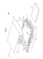
- FIG. 2 is a first exploded perspective view of a receiver of an embodiment of the present invention.
- a receiver 100 of the embodiment of the present invention is a device, such as a set-top box, configured to receive a digital broadcasting signal.
- the receiver 100 of the embodiment of the present invention functions as a receiver when a contact type IC (Integrated Circuit) card, called a B-CAS card 20, is inserted.
- An IC chip not illustrated in FIG. 2 , is mounted on the B-CAS card 20.
- An identification number and a cryptographic key peculiar to the card are stored in the IC chip.
- the receiver 100 includes a case main body 110 and a cover part 120.
- An electric power supply board 130 and a digital board 140 are received in the case main body 110.
- a inserting opening 111 where the B-CAS card 20 is inserted is formed in the case main body 110. By inserting the B-CAS card 20 into the inserting opening 111, the B-CAS card is connected to a B-CAS card connector 150 (see FIG. 3 ) discussed below.
- An electric power supply circuit mainly consisting of an analog circuit and the B-CAS card connector 150 are mounted on the electric power supply board 130 of the embodiment of the present invention.
- Two-surface (both-surfaces) mounting can be realized on the digital board 140 of the embodiment of the present invention.
- a digital circuit such as a CPU (Central Processing Unit) or a memory chip is mounted on a surface of the digital board 140 situated at the cover part 120 side.
- a tuner 160 is mounted on a surface of the digital board 140 situated at an opposite side to the cover part 120 side.
- the tuner 160 is configured to receive a digital broadcasting signal.
- Pins 141 shown in FIG. 2 are pins of the tuner 160 (See FIG. 3 ).
- a guide member 170 is provided at the cover part 120 (See FIG. 4 ).
- the guide member 170 is a plate-shaped member which is formed in a body at the cover part 120.
- the guide member 170 is configured to guide the B-CAS card 20 to a card inserting opening 151 of the B-CAS card connector 150.
- a piercing hole 142 is formed in the digital board 140.
- the piercing hole 142 is configured have the guide member 170 inserted in a case where the case main body 110 and the cover part 120 are connected to each other.
- the guide member 170 is inserted into the piercing hole 142, and the B-CAS card 20 inserted from the inserting opening 111 comes in contact with a head end of the guide member 170 just in front of the B-CAS card connector 150 so as to be guided to the card inserting opening 151.
- FIG. 3 is a second exploded perspective view of the receiver 100 of the embodiment of the present invention.
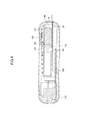
- FIG. 4 is a cross-sectional view taken along a line A-A of FIG. 2 of the receiver 100 of the embodiment of the present invention.
- FIG. 3 illustration of the digital board 140 is omitted.
- FIG. 4 shows a state where the B-CAS card 20 is inserted.
- the tuner 160 is provided between the inserting opening 111 of the case main body 110 and the card inserting opening 151 of the B-CAS card connector 150.
- the digital board 140 is stacked over the electric power supply board 130 so that the tuner 160 provided on the digital board 140 and the B-CAS card connector 150 provided on the electric power supply board 130 face each other. Since the digital board 140 is stacked over the electric power supply board 130, the tuner 160 is positioned between the inserting opening 111 of the case main body 110 and the card inserting opening 151 of the B-CAS card connector 150.
- a length W1 between the inserting opening 111 of the case main body 110 and the card inserting opening 151 of the B-CAS card connector 150 is designed so that an entirety of the B-CAS card 20 is received in the case main body 110 in a case where the B-CAS card 20 is inserted in the B-CAS card connector 150.
- the tuner 160 since the tuner 160 is in a space between the inserting opening 111 of the case main body 110 and the card inserting opening 151 of the B-CAS card connector 150, the space being not conventionally used, it is possible to miniaturize the receiver 100. Furthermore, in this embodiment, as shown in FIG. 4 , the tuner 160 is positioned so as not to come in contact with the B-CAS card 20 in a case where the B-CAS card 20 is inserted in the B-CAS card connector 150.
- the tuner 160 is positioned so as not to be overlapped with the inserting opening 111 and the card inserting opening 151 and thereby a surface S of the tuner 160 does not interfere with the path of the B-CAS card 20 in an inserting direction of the B-CAS card 20 from the inserting opening 111 to the card inserting opening 151 in the case where the B-CAS card 20 is inserted.
- the B-CAS card 20 can be inserted into the B-CAS card connector 150 without being obstructed by the tuner 160 at the time when the B-CAS card 20 is inserted.
- the tuner 160 of this embodiment functions as an auxiliary guide member configured to assist the guide member 170.
- the B-CAS card 20 is led to the guide member 170 along the surface S of the tuner 160.
- the B-CAS card 20 is guided by the guide member 170 so as to be inserted into the B-CAS card connector 150.
- the tuner 160 is provided so that the surface S of the tuner 160 is along the path from the inserting opening 111 to the card inserting opening 151 when the B-CAS card 20 is inserted.
- the tuner 160 can function as the auxiliary guide member from the inserting opening 111 to the guide member 170.
- the guide member 170 of this embodiment can be a plate-shaped member formed on a rear surface of the cover part 120. Hence, the guide member can have a structure smaller and simpler than that of the related art guide member.
- the guide member 170 may not be provided but only the tuner 160 may be used as the guide member.
- the surface S of the tuner 160 may be covered with a resin film or the like. By covering the surface S, it is possible to prevent the surface of the B-CAS card 20 from being damaged by the tuner 160 at the time when the B-CAS card 20 is inserted.
- the digital board 140 of this embodiment is discussed.
- arrangement of the tuner 160 at the digital board 140 is made in a special manner so that the digital board 140 can be miniaturized.
- FIG. 5 is a view for explaining the digital board 140 of the embodiment of the present invention.
- FIG. 5 shows an example of a board layout at the cover part 120 side of the digital board 140.
- the tuner 160 is mounted on a surface at a side opposite to the surface shown in FIG. 5 of the digital board 140.
- a side of the tuner 160 where the number of pins 141 is larger is positioned at an end part of the digital board 140.
- Through holes 144 are formed at an end part of the digital board 140.
- the through holes 144 are configured to have inserted the pins 141 of the tuner 160.
- the tuner 160 is mounted on the digital board 140 by inserting the pins 141 into the through holes 144.
- the side of the tuner 160 where the number of pins 141 is larger is positioned at the end part of the digital board 140, it is possible to prevent the through holes 144 from being formed in the vicinity of the center part of the digital board 140. Therefore, in the digital board 140 of this embodiment, it is possible to mount an IC, connected to a large number of signal lines, at an area H situated at an opposite side to an area where the tuner 160 is mounted. Therefore, high integration of the digital board 140 can be achieved.
- the tuner 160 since the tuner 160 is mounted on the digital board 140, a video signal line in the periphery of the tuner 160 is wired to the digital board 140. Therefore, it is possible to reduce noise of the video signal. Furthermore, the number of the signal lines configured to connect the electric power supply board 130 and the digital board 140 to each other can be decreased. The number of pins of a connector configured to connect the electric power supply board 130 and the digital board 140 can be made small.
- a debug circuit port is provided at an end part of the digital board 140. Because of this structure, the digital board 140 can be miniaturized.
- FIG. 6 is a view for explaining the debug circuit port of the related art digital board.
- the digital board 50 shown in FIG. 6 is received in, for example, the related art receiver 10.
- a digital board for development is formed and a debugging process of an IC mounted on the board is applied by using the digital board for development.
- a connector for debugging is provided on the digital board for development.
- the connector for debugging is predetermined based on a specification of an IC such as a CPU being a subject of the debugging.
- the connector for debugging is connected to a debug device or the like.
- the digital board 50 shown in FIG. 6 is the digital board for mass production.
- the digital board 50 Since the digital board 50 is produced in large quantities in a state where the connector for debugging is removed from the digital board for development, a pattern 51 for attaching the connector for debugging remains on the digital board. This pattern 51 is not necessary for the digital board for mass production. An area where the pattern 51 is formed is a useless area.
- the digital board 140 of this embodiment includes debug circuit ports 145 and 146 configured to connect a debug circuit.
- the debug circuit ports 145 and 146 are formed in component prohibited areas situated at both ends of the digital board 140.
- the component prohibited areas are used for supporting the digital board 140 in a manufacturing process of the digital board 140. It is prohibited to mount components in the component prohibited areas.
- the debug circuit ports 145 and 146 of this embodiment the same number of the ports as the number of signals necessary for debugging the IC mounted on the digital board 140 is formed. Therefore, the number of the ports of the debug circuit ports 145 and 146 is smaller than the number of pins of the related art debug connector.
- the debug circuits which are separately made in advance are connected into the debug circuit ports 145 and 146 so that the debugging is performed.
- this structure in this embodiment, it is possible to perform the debugging for each of the digital boards 140 even after the mass production of the digital boards 140. Therefore, in a case where a problem occurs in the product, it is possible to inspect every product for the problem.
- a receiver (100) including a case main body (110) with an opening (111) for inserting a contact type IC card (20); an electric power supply board (130) provided in the case main body (100); a contact type IC card connector (150) where the contact type IC card (20) is expected to be connected; and a tuner (160) configured to receive a digital broadcasting signal, wherein the contact type IC card connector (150) is provided in a position so that an entirety of the contact type IC card (20) is received in the case main body (110) in a case where the contact type IC card (20) is inserted through the inserting opening (111) on the electric power supply board (130); and the tuner (160) is situated in a position between the inserting opening (111) and the contact type IC card connector (150), the position being where the tuner (160) does not come in contact with the contact type IC card (20) in the case where the contact type IC card (20) is inserted.
- the tuner (160) may be provided on a digital board (140), and the digital board (140) is received in the case main body (110).
- the receiver (100) may further include a cover part (120) configured to cover the case main body (110); and a plate-shaped guide member (170) formed from the cover part (120) in a direction toward the case main body (110), the plate-shaped guide member (170) being configured to guide the contact type IC card (20) to the contact type IC card connector (150), wherein a piercing hole (142) is formed in the digital board (140), and the piercing hole (142) is configured to have the plate-shaped guide member (170) inserted.
- the contact type TC card connector (150) may be provided on the electric power supply board (130); and the electric power supply board (130) and the digital board (140) may face each other.
- the tuner (160) may be provided so that a surface of the tuner (160) is along a path of the connect type IC card (20) from the inserting opening (111) to a card inserting opening (151) of the contact type card connector (150).
Landscapes
- Engineering & Computer Science (AREA)
- Multimedia (AREA)
- Signal Processing (AREA)
- Structure Of Receivers (AREA)
- Coupling Device And Connection With Printed Circuit (AREA)
Abstract
A receiver includes a case main body with an opening for inserting an IC card; an electric power supply board provided in the case main body; a contact type IC card connector where the contact type IC card is expected to be connected; and a tuner configured to receive a digital broadcasting signal, wherein the contact type IC card connector is provided in a position so that an entirety of the contact type card is received in the case main body in a case where the contact type IC card is inserted through the inserting opening on the electric power supply board; and the tuner is situated in a position between the inserting opening and the contact type IC card connector, the position being where the tuner does not come in contact with the contact type IC card in the case where the contact type IC card is inserted.
Description
- This patent application is based upon and claims the benefit of priority of Japanese Patent Application No.
2010-104264 filed on April 28, 2010 - The present invention generally relates to receivers. More specifically, the present invention relates to a receiver including a case main body with an opening for inserting a contact type IC card, an electric power supply board provided in the case main body, a contact type IC card connector where the contact type IC card is connected, and a tuner configured to receive a digital broadcasting signal.
- In recent years, a broadcasting method of television broadcasting has been changing from an analog method to a digital method. Based on the change of the broadcasting method, for example, a receiver configured to receive a digital broadcasting signal such as terrestrial television broadcasting and convert the broadcasting signal to an audio-visual signal which can be used by a normal television has been commercialized.
-
FIG. 1 is a perspective view of arelated art receiver 10. When a card 11 for receiving a digital broadcasting signal is inserted, therelated art receiver 10 functions as a receiver of the digital broadcasting signal. - The
receiver 10 includes amain body part 12 and acover part 13. Ananalog board 14 and a digital board not illustrated inFIG. 1 are received in themain body part 12. Acard inserting part 15 is formed in themain body part 12. An electricpower supply circuit 16, aconnector 17 where the contact type IC card 11 is connected, atuner 18, and aguide member 19 configured to guide the contact type IC card 11 to theconnector 17 are mounted on theanalog board 14. A length W of theguide member 19 is designed so that the entirety of the contact type IC card 11 is received in themain body part 12 when the contact type IC card 11 is connected into theconnector 17. In addition, theguide member 19 is provided on theanalog board 14 so that acard inserting slit 21 is provided at thecard inserting part 15. - With this structure, the contact type IC card 11 is guided by the
guide member 19 so as to be connected into theconnector 17 so that thereceiver 10 functions as a receiver. A video displaying device including a card receiving part having a card inserting stand is discussed in Japanese Laid-Open Patent Application Publication No.2003-55115 - Conventionally, in the receiver, as well as other electronic devices, further miniaturization and cost reduction have been in demand.
- Accordingly, embodiments of the present invention may provide a novel and useful receiver solving one or more of the problems discussed above.
- More specifically, the embodiments of the present invention may provide a receiver that can be miniaturized while a manufacturing cost is reduced.
- Another aspect of the embodiments of the present invention may be to provide a receiver including a case main body with an opening for inserting a contact type IC card; an electric power supply board provided in the case main body; a contact type IC card connector where the contact type IC card is expected to be connected; and a tuner configured to receive a digital broadcasting signal, wherein the contact type IC card connector is provided in a position so that an entirety of the contact type IC card is received in the case main body in a case where the contact type IC card is inserted through the inserting opening on the electric power supply board; and the tuner is situated in a position between the inserting opening and the contact type IC card connector, the position being where the tuner does not come in contact with the contact type IC card in the case where the contact type IC card is inserted.
- According to the embodiment of the present invention, a receiver can be miniaturized while a manufacturing cost is reduced.
- Additional objects and advantages of the embodiments are set forth in part in the description which follows, and in part will become obvious from the description, or may be learned by practice of the invention. The object and advantages of the invention will be realized and attained by means of the elements and combinations particularly pointed out in the appended claims. It is to be understood that both the foregoing general description and the following detailed description are exemplary and explanatory and are not restrictive of the invention as claimed.
-
-
FIG. 1 is a perspective view of a related art receiver; -
FIG. 2 is a first exploded perspective view of a receiver of an embodiment of the present invention; -
FIG. 3 is a second exploded perspective view of the receiver of the embodiment of the present invention; -
FIG. 4 is a cross-sectional view taken along a line A-A ofFIG. 2 of the receiver of the embodiment of the present invention; -
FIG. 5 is a view for explaining a digital board of the embodiment of the present invention; and -
FIG. 6 is a view for explaining a debug circuit port of the digital board. - In an embodiment of the present invention, by effectively using a space which is not conventionally used and making a size of a guide member configured to guide a contact type IC card smaller, it is possible to realize a receiver that can be miniaturized while a manufacturing cost is reduced.
- A description of a receiver is given below, with reference to the
FIG. 2 through FIG. 6 of embodiments of the present invention. -
FIG. 2 is a first exploded perspective view of a receiver of an embodiment of the present invention. - A
receiver 100 of the embodiment of the present invention is a device, such as a set-top box, configured to receive a digital broadcasting signal. Thereceiver 100 of the embodiment of the present invention functions as a receiver when a contact type IC (Integrated Circuit) card, called a B-CAS card 20, is inserted. An IC chip, not illustrated inFIG. 2 , is mounted on the B-CAS card 20. An identification number and a cryptographic key peculiar to the card are stored in the IC chip. - The
receiver 100 includes a casemain body 110 and acover part 120. An electricpower supply board 130 and adigital board 140 are received in the casemain body 110. Ainserting opening 111 where the B-CAS card 20 is inserted is formed in the casemain body 110. By inserting the B-CAS card 20 into theinserting opening 111, the B-CAS card is connected to a B-CAS card connector 150 (seeFIG. 3 ) discussed below. - An electric power supply circuit mainly consisting of an analog circuit and the B-
CAS card connector 150 are mounted on the electricpower supply board 130 of the embodiment of the present invention. Two-surface (both-surfaces) mounting can be realized on thedigital board 140 of the embodiment of the present invention. As shown inFIG. 5 , a digital circuit such as a CPU (Central Processing Unit) or a memory chip is mounted on a surface of thedigital board 140 situated at thecover part 120 side. As shown inFIG. 4 , atuner 160 is mounted on a surface of thedigital board 140 situated at an opposite side to thecover part 120 side. Thetuner 160 is configured to receive a digital broadcasting signal.Pins 141 shown inFIG. 2 are pins of the tuner 160 (SeeFIG. 3 ). - In the
receiver 100 of the embodiment of the present invention, aguide member 170 is provided at the cover part 120 (SeeFIG. 4 ). Theguide member 170 is a plate-shaped member which is formed in a body at thecover part 120. Theguide member 170 is configured to guide the B-CAS card 20 to a card inserting opening 151 of the B-CAS card connector 150. Apiercing hole 142 is formed in thedigital board 140. Thepiercing hole 142 is configured have theguide member 170 inserted in a case where the casemain body 110 and thecover part 120 are connected to each other. In thereceiver 100 of the embodiment of the present invention, in the case where the casemain body 110 and thecover part 120 are connected to each other, theguide member 170 is inserted into thepiercing hole 142, and the B-CAS card 20 inserted from theinserting opening 111 comes in contact with a head end of theguide member 170 just in front of the B-CAS card connector 150 so as to be guided to the card inserting opening 151. - The
receiver 100 of the embodiment of the present invention is further discussed with reference toFIG. 3 andFIG. 4 .FIG. 3 is a second exploded perspective view of thereceiver 100 of the embodiment of the present invention.FIG. 4 is a cross-sectional view taken along a line A-A ofFIG. 2 of thereceiver 100 of the embodiment of the present invention. - In
FIG. 3 , illustration of thedigital board 140 is omitted.FIG. 4 shows a state where the B-CAS card 20 is inserted. - As shown in
FIG. 3 , in thereceiver 100 of the embodiment of the present invention, thetuner 160 is provided between the insertingopening 111 of the casemain body 110 and thecard inserting opening 151 of the B-CAS card connector 150. - The
digital board 140 is stacked over the electricpower supply board 130 so that thetuner 160 provided on thedigital board 140 and the B-CAS card connector 150 provided on the electricpower supply board 130 face each other. Since thedigital board 140 is stacked over the electricpower supply board 130, thetuner 160 is positioned between the insertingopening 111 of the casemain body 110 and thecard inserting opening 151 of the B-CAS card connector 150. - A length W1 between the inserting
opening 111 of the casemain body 110 and thecard inserting opening 151 of the B-CAS card connector 150 is designed so that an entirety of the B-CAS card 20 is received in the casemain body 110 in a case where the B-CAS card 20 is inserted in the B-CAS card connector 150. - In this embodiment, since the
tuner 160 is in a space between the insertingopening 111 of the casemain body 110 and thecard inserting opening 151 of the B-CAS card connector 150, the space being not conventionally used, it is possible to miniaturize thereceiver 100. Furthermore, in this embodiment, as shown inFIG. 4 , thetuner 160 is positioned so as not to come in contact with the B-CAS card 20 in a case where the B-CAS card 20 is inserted in the B-CAS card connector 150. In other words, thetuner 160 is positioned so as not to be overlapped with the insertingopening 111 and thecard inserting opening 151 and thereby a surface S of thetuner 160 does not interfere with the path of the B-CAS card 20 in an inserting direction of the B-CAS card 20 from the insertingopening 111 to thecard inserting opening 151 in the case where the B-CAS card 20 is inserted. In this embodiment, with this structure, the B-CAS card 20 can be inserted into the B-CAS card connector 150 without being obstructed by thetuner 160 at the time when the B-CAS card 20 is inserted. - In addition, the
tuner 160 of this embodiment functions as an auxiliary guide member configured to assist theguide member 170. In other words, in this embodiment, the B-CAS card 20 is led to theguide member 170 along the surface S of thetuner 160. The B-CAS card 20 is guided by theguide member 170 so as to be inserted into the B-CAS card connector 150. - Thus, in this embodiment, the
tuner 160 is provided so that the surface S of thetuner 160 is along the path from the insertingopening 111 to thecard inserting opening 151 when the B-CAS card 20 is inserted. With this structure, thetuner 160 can function as the auxiliary guide member from the insertingopening 111 to theguide member 170. - Therefore, the
guide member 170 of this embodiment can be a plate-shaped member formed on a rear surface of thecover part 120. Hence, the guide member can have a structure smaller and simpler than that of the related art guide member. - In this embodiment, for example, the
guide member 170 may not be provided but only thetuner 160 may be used as the guide member. In this case, the surface S of thetuner 160 may be covered with a resin film or the like. By covering the surface S, it is possible to prevent the surface of the B-CAS card 20 from being damaged by thetuner 160 at the time when the B-CAS card 20 is inserted. - Next, the
digital board 140 of this embodiment is discussed. In this embodiment, arrangement of thetuner 160 at thedigital board 140 is made in a special manner so that thedigital board 140 can be miniaturized. -
FIG. 5 is a view for explaining thedigital board 140 of the embodiment of the present invention.FIG. 5 shows an example of a board layout at thecover part 120 side of thedigital board 140. Thetuner 160 is mounted on a surface at a side opposite to the surface shown inFIG. 5 of thedigital board 140. In this embodiment, a side of thetuner 160 where the number ofpins 141 is larger is positioned at an end part of thedigital board 140. - Through
holes 144 are formed at an end part of thedigital board 140. The throughholes 144 are configured to have inserted thepins 141 of thetuner 160. Thetuner 160 is mounted on thedigital board 140 by inserting thepins 141 into the throughholes 144. In this embodiment, since the side of thetuner 160 where the number ofpins 141 is larger is positioned at the end part of thedigital board 140, it is possible to prevent the throughholes 144 from being formed in the vicinity of the center part of thedigital board 140. Therefore, in thedigital board 140 of this embodiment, it is possible to mount an IC, connected to a large number of signal lines, at an area H situated at an opposite side to an area where thetuner 160 is mounted. Therefore, high integration of thedigital board 140 can be achieved. - In addition, in this embodiment, since the
tuner 160 is mounted on thedigital board 140, a video signal line in the periphery of thetuner 160 is wired to thedigital board 140. Therefore, it is possible to reduce noise of the video signal. Furthermore, the number of the signal lines configured to connect the electricpower supply board 130 and thedigital board 140 to each other can be decreased. The number of pins of a connector configured to connect the electricpower supply board 130 and thedigital board 140 can be made small. - In addition, a debug circuit port is provided at an end part of the
digital board 140. Because of this structure, thedigital board 140 can be miniaturized. - Next, with reference to
FIG. 6 , a debug circuit port of the related art digital board is discussed. Here,FIG. 6 is a view for explaining the debug circuit port of the related art digital board. - The
digital board 50 shown inFIG. 6 is received in, for example, therelated art receiver 10. In the related art, when thereceiver 10 is developed, a digital board for development is formed and a debugging process of an IC mounted on the board is applied by using the digital board for development. A connector for debugging is provided on the digital board for development. The connector for debugging is predetermined based on a specification of an IC such as a CPU being a subject of the debugging. When the debugging is performed, the connector for debugging is connected to a debug device or the like. - In the conventional art, when the debugging for the digital board for development is completed, a digital board for mass production is manufactured in a state where the connector for debugging is removed. The
digital board 50 shown inFIG. 6 is the digital board for mass production. - Since the
digital board 50 is produced in large quantities in a state where the connector for debugging is removed from the digital board for development, apattern 51 for attaching the connector for debugging remains on the digital board. Thispattern 51 is not necessary for the digital board for mass production. An area where thepattern 51 is formed is a useless area. - In this embodiment, by eliminating a pattern unnecessary for the digital board for mass production, miniaturization of the
digital board 140 is realized. - Referring back to
FIG. 5 , thedigital board 140 of this embodiment includesdebug circuit ports debug circuit ports digital board 140. The component prohibited areas are used for supporting thedigital board 140 in a manufacturing process of thedigital board 140. It is prohibited to mount components in the component prohibited areas. In addition, in thedebug circuit ports digital board 140 is formed. Therefore, the number of the ports of thedebug circuit ports - When the debugging of the
digital board 140 of this embodiment is performed, the debug circuits which are separately made in advance are connected into thedebug circuit ports digital boards 140 even after the mass production of thedigital boards 140. Therefore, in a case where a problem occurs in the product, it is possible to inspect every product for the problem. - All examples and conditional language recited herein are intended for pedagogical purposes to aid the reader in understanding the invention and the concepts contributed by the inventor to furthering the art, and are to be construed as being without limitation to such specifically recited examples and conditions, nor does the organization of such examples in the specification relate to a showing of the superiority or inferiority of the invention. Although the embodiments of the present invention have been described in detail, it should be understood that the various changes, substitutions, and alterations could be made hereto without departing from the spirit and scope of the invention.
- Thus, according to the embodiment of the present invention, it is possible to provide a receiver (100), including a case main body (110) with an opening (111) for inserting a contact type IC card (20); an electric power supply board (130) provided in the case main body (100); a contact type IC card connector (150) where the contact type IC card (20) is expected to be connected; and a tuner (160) configured to receive a digital broadcasting signal, wherein the contact type IC card connector (150) is provided in a position so that an entirety of the contact type IC card (20) is received in the case main body (110) in a case where the contact type IC card (20) is inserted through the inserting opening (111) on the electric power supply board (130); and the tuner (160) is situated in a position between the inserting opening (111) and the contact type IC card connector (150), the position being where the tuner (160) does not come in contact with the contact type IC card (20) in the case where the contact type IC card (20) is inserted.
- The tuner (160) may be provided on a digital board (140), and the digital board (140) is received in the case main body (110).
- The receiver (100) may further include a cover part (120) configured to cover the case main body (110); and a plate-shaped guide member (170) formed from the cover part (120) in a direction toward the case main body (110), the plate-shaped guide member (170) being configured to guide the contact type IC card (20) to the contact type IC card connector (150), wherein a piercing hole (142) is formed in the digital board (140), and the piercing hole (142) is configured to have the plate-shaped guide member (170) inserted.
- The contact type TC card connector (150) may be provided on the electric power supply board (130); and the electric power supply board (130) and the digital board (140) may face each other.
- The tuner (160) may be provided so that a surface of the tuner (160) is along a path of the connect type IC card (20) from the inserting opening (111) to a card inserting opening (151) of the contact type card connector (150).
- It should be noted that the numerical references in the parentheses mentioned above are provided for easy understanding and are just examples. The interpretation of claim language is not limited to these examples.
Claims (5)
- A receiver, comprising:a case main body with an opening for inserting a contact type IC card;an electric power supply board provided in the case main body;a contact type IC card connector where the contact type IC card is expected to be connected; anda tuner configured to receive a digital broadcasting signal,wherein the contact type IC card connector is provided in a position so that an entirety of the contact type IC card is received in the case main body in a case where the contact type IC card is inserted through the inserting opening on the electric power supply board; and
the tuner is situated in a position between the inserting opening and the contact type IC card connector, the position being where the tuner does not come in contact with the contact type IC card in the case where the contact type IC card is inserted. - The receiver as claimed in claim 1, wherein the tuner is provided on a digital board; and
the digital board is received in the case main body. - The receiver as claimed in claim 2, further comprising:a cover part configured to cover the case main body; anda plate-shaped guide member formed from the cover part in a direction toward the case main body, the plate-shaped guide member being configured to guide the contact type IC card to the contact type IC card Connector,wherein a piercing hole is formed in the digital board, and the piercing hole is configured to have the plate-shaped guide member inserted.
- The receiver as claimed in claim 2, wherein the contact type IC card connector is provided on the electric power supply board; and
the electric power supply board and the digital board face each other. - The receiver as claimed in claim 1, wherein the tuner is provided so that a surface of the tuner is along a path of the contact type IC card from the inserting opening to a card inserting opening of the contact type card connector.
Applications Claiming Priority (1)
| Application Number | Priority Date | Filing Date | Title |
|---|---|---|---|
| JP2010104264A JP5531759B2 (en) | 2010-04-28 | 2010-04-28 | Receiver |
Publications (1)
| Publication Number | Publication Date |
|---|---|
| EP2383988A1 true EP2383988A1 (en) | 2011-11-02 |
Family
ID=44244258
Family Applications (1)
| Application Number | Title | Priority Date | Filing Date |
|---|---|---|---|
| EP11162579A Withdrawn EP2383988A1 (en) | 2010-04-28 | 2011-04-15 | Receiver |
Country Status (4)
| Country | Link |
|---|---|
| US (1) | US20110267548A1 (en) |
| EP (1) | EP2383988A1 (en) |
| JP (1) | JP5531759B2 (en) |
| CN (1) | CN102238352A (en) |
Cited By (1)
| Publication number | Priority date | Publication date | Assignee | Title |
|---|---|---|---|---|
| EP3016398A3 (en) * | 2014-10-28 | 2016-05-11 | Samsung Electronics Co., Ltd. | Set-top box and display apparatus having discrete-type card portion, and card portion-mounting methods thereof |
Citations (4)
| Publication number | Priority date | Publication date | Assignee | Title |
|---|---|---|---|---|
| JP2003055115A (en) | 2001-08-14 | 2003-02-26 | Meiji Seika Kaisha Ltd | Insecticidal and fungicidal mix composition for paddy rice |
| WO2009057124A2 (en) * | 2007-11-01 | 2009-05-07 | Innomedia Technologies Pvt. Ltd. | A set-top-box cabinet for natural cooling of internal electronics |
| CN201294592Y (en) * | 2008-10-17 | 2009-08-19 | 深圳市同洲电子股份有限公司 | Set-top box cabinet |
| JP2010104264A (en) | 2008-10-28 | 2010-05-13 | Globeride Inc | Fishing rod |
Family Cites Families (4)
| Publication number | Priority date | Publication date | Assignee | Title |
|---|---|---|---|---|
| JP2006310965A (en) * | 2005-04-26 | 2006-11-09 | Orion Denki Kk | Digital broadcast receiver |
| JP3113691U (en) * | 2005-06-14 | 2005-09-15 | オリオン電機株式会社 | Digital broadcast receiver having a shield structure |
| JP2007174711A (en) * | 2007-03-26 | 2007-07-05 | Fujifilm Corp | Electronic image recording device |
| JP2009100384A (en) * | 2007-10-18 | 2009-05-07 | Fujitsu Ten Ltd | Electronic equipment |
-
2010
- 2010-04-28 JP JP2010104264A patent/JP5531759B2/en not_active Expired - Fee Related
-
2011
- 2011-04-07 US US13/081,870 patent/US20110267548A1/en not_active Abandoned
- 2011-04-15 EP EP11162579A patent/EP2383988A1/en not_active Withdrawn
- 2011-04-27 CN CN2011101119419A patent/CN102238352A/en active Pending
Patent Citations (4)
| Publication number | Priority date | Publication date | Assignee | Title |
|---|---|---|---|---|
| JP2003055115A (en) | 2001-08-14 | 2003-02-26 | Meiji Seika Kaisha Ltd | Insecticidal and fungicidal mix composition for paddy rice |
| WO2009057124A2 (en) * | 2007-11-01 | 2009-05-07 | Innomedia Technologies Pvt. Ltd. | A set-top-box cabinet for natural cooling of internal electronics |
| CN201294592Y (en) * | 2008-10-17 | 2009-08-19 | 深圳市同洲电子股份有限公司 | Set-top box cabinet |
| JP2010104264A (en) | 2008-10-28 | 2010-05-13 | Globeride Inc | Fishing rod |
Cited By (1)
| Publication number | Priority date | Publication date | Assignee | Title |
|---|---|---|---|---|
| EP3016398A3 (en) * | 2014-10-28 | 2016-05-11 | Samsung Electronics Co., Ltd. | Set-top box and display apparatus having discrete-type card portion, and card portion-mounting methods thereof |
Also Published As
| Publication number | Publication date |
|---|---|
| JP5531759B2 (en) | 2014-06-25 |
| JP2011234235A (en) | 2011-11-17 |
| US20110267548A1 (en) | 2011-11-03 |
| CN102238352A (en) | 2011-11-09 |
Similar Documents
| Publication | Publication Date | Title |
|---|---|---|
| US6674644B2 (en) | Module and connector having multiple contact rows | |
| US7815467B2 (en) | Connector device | |
| US7874874B2 (en) | Connecting device having a build-in digital television tuner | |
| US7967632B2 (en) | Card connector | |
| US8848395B2 (en) | Securing mechanism and electronic device with connector cover | |
| US9949389B2 (en) | Image processing board and display apparatus having the same | |
| EP2575214B1 (en) | Socket for two cameras, camera module and terminal device | |
| US20130166806A1 (en) | Pci riser card | |
| US20110267548A1 (en) | Receiver | |
| JP5569128B2 (en) | Receiver | |
| KR102110972B1 (en) | Separation type tuner | |
| US6781828B2 (en) | Display having a detachable TV card | |
| US10412831B2 (en) | Circuit board and layout structure | |
| US20110273825A1 (en) | Receiving device and manufacturing method thereof | |
| KR20090001086A (en) | Tuner Connector | |
| US20040212726A1 (en) | Electronic image-capture module | |
| JP2011040334A (en) | Connection structure and connection method for high-frequency module | |
| US8406002B2 (en) | Low noise block down-converter with integrated feed | |
| US20140226294A1 (en) | Display device | |
| US20070059993A1 (en) | Signal line socket | |
| US20110164353A1 (en) | Electronic device with function expansion capabilities | |
| JP2008085676A (en) | Receiver and composite receiver | |
| JP2020123698A (en) | Electronic device | |
| KR20260030599A (en) | Integrated module with multiple functions | |
| KR20070040438A (en) | Tuner fixtures for electronics |
Legal Events
| Date | Code | Title | Description |
|---|---|---|---|
| AK | Designated contracting states |
Kind code of ref document: A1 Designated state(s): AL AT BE BG CH CY CZ DE DK EE ES FI FR GB GR HR HU IE IS IT LI LT LU LV MC MK MT NL NO PL PT RO RS SE SI SK SM TR |
|
| AX | Request for extension of the european patent |
Extension state: BA ME |
|
| PUAI | Public reference made under article 153(3) epc to a published international application that has entered the european phase |
Free format text: ORIGINAL CODE: 0009012 |
|
| 17P | Request for examination filed |
Effective date: 20120412 |
|
| STAA | Information on the status of an ep patent application or granted ep patent |
Free format text: STATUS: THE APPLICATION HAS BEEN WITHDRAWN |
|
| 18W | Application withdrawn |
Effective date: 20121220 |