EP2383855B1 - Arc flash detection system and method - Google Patents
Arc flash detection system and method Download PDFInfo
- Publication number
- EP2383855B1 EP2383855B1 EP11164071.0A EP11164071A EP2383855B1 EP 2383855 B1 EP2383855 B1 EP 2383855B1 EP 11164071 A EP11164071 A EP 11164071A EP 2383855 B1 EP2383855 B1 EP 2383855B1
- Authority
- EP
- European Patent Office
- Prior art keywords
- light
- diaphragm
- arc flash
- sensor
- optical fibers
- Prior art date
- Legal status (The legal status is an assumption and is not a legal conclusion. Google has not performed a legal analysis and makes no representation as to the accuracy of the status listed.)
- Active
Links
- 238000001514 detection method Methods 0.000 title claims description 34
- 238000000034 method Methods 0.000 title claims description 18
- 239000013307 optical fiber Substances 0.000 claims description 44
- 230000001681 protective effect Effects 0.000 claims description 11
- 230000003287 optical effect Effects 0.000 claims description 7
- 239000000463 material Substances 0.000 claims description 5
- 238000012545 processing Methods 0.000 claims description 4
- 238000001914 filtration Methods 0.000 claims 2
- 230000003213 activating effect Effects 0.000 claims 1
- 239000000356 contaminant Substances 0.000 claims 1
- 230000023077 detection of light stimulus Effects 0.000 claims 1
- 239000000835 fiber Substances 0.000 description 25
- 230000004044 response Effects 0.000 description 11
- 239000010408 film Substances 0.000 description 8
- 229920006254 polymer film Polymers 0.000 description 8
- 238000010586 diagram Methods 0.000 description 7
- 238000009826 distribution Methods 0.000 description 7
- 239000002184 metal Substances 0.000 description 7
- 239000004020 conductor Substances 0.000 description 5
- 238000009413 insulation Methods 0.000 description 5
- 230000005540 biological transmission Effects 0.000 description 4
- 230000008569 process Effects 0.000 description 3
- 238000005253 cladding Methods 0.000 description 2
- 238000000151 deposition Methods 0.000 description 2
- 230000008021 deposition Effects 0.000 description 2
- 238000013461 design Methods 0.000 description 2
- 238000004519 manufacturing process Methods 0.000 description 2
- 239000010409 thin film Substances 0.000 description 2
- 239000012780 transparent material Substances 0.000 description 2
- 238000013459 approach Methods 0.000 description 1
- 238000003491 array Methods 0.000 description 1
- 230000008878 coupling Effects 0.000 description 1
- 238000010168 coupling process Methods 0.000 description 1
- 238000005859 coupling reaction Methods 0.000 description 1
- 230000003111 delayed effect Effects 0.000 description 1
- 230000009977 dual effect Effects 0.000 description 1
- 238000004880 explosion Methods 0.000 description 1
- 239000002360 explosive Substances 0.000 description 1
- 239000007789 gas Substances 0.000 description 1
- 230000036039 immunity Effects 0.000 description 1
- 239000010410 layer Substances 0.000 description 1
- 239000007788 liquid Substances 0.000 description 1
- 230000007246 mechanism Effects 0.000 description 1
- 230000000116 mitigating effect Effects 0.000 description 1
- 238000012986 modification Methods 0.000 description 1
- 230000004048 modification Effects 0.000 description 1
- 230000007935 neutral effect Effects 0.000 description 1
- 230000002265 prevention Effects 0.000 description 1
- 230000005855 radiation Effects 0.000 description 1
- 230000035945 sensitivity Effects 0.000 description 1
- 238000004088 simulation Methods 0.000 description 1
- 239000002356 single layer Substances 0.000 description 1
- 239000007787 solid Substances 0.000 description 1
- 238000012360 testing method Methods 0.000 description 1
- 238000000427 thin-film deposition Methods 0.000 description 1
Images


Classifications
-
- H—ELECTRICITY
- H02—GENERATION; CONVERSION OR DISTRIBUTION OF ELECTRIC POWER
- H02H—EMERGENCY PROTECTIVE CIRCUIT ARRANGEMENTS
- H02H1/00—Details of emergency protective circuit arrangements
- H02H1/0007—Details of emergency protective circuit arrangements concerning the detecting means
- H02H1/0015—Using arc detectors
- H02H1/0023—Using arc detectors sensing non electrical parameters, e.g. by optical, pneumatic, thermal or sonic sensors
Definitions
- the invention relates generally to arc flash detection and, in particular, to arc flash sensors.
- Electric power circuits and switchgear equipment have conductors separated by insulation. Air space often serves as part or all of this insulation in some applications. If the conductors are too close to each other or voltage exceeds the insulation level, an arc can occur between conductors. Air or any other insulation (gas, solid, or liquid) between conductors can become ionized, making the insulation conductive and thereby enabling an arcing event. Arc events may induce temperatures that can reach as high as 20,000° C, vaporize conductors and adjacent materials, and release an explosive energy that destroys surrounding circuits.
- An arc flash is typically the result of a rapid energy release due to an arcing fault between two phases or between one phase and a neutral or ground.
- An arc flash can produce high heat, intense light, and acoustic waves similar to that of an explosion.
- an arc fault current typically includes a much lower magnitude as compared to a short circuit current, and circuit breakers do not necessarily react to such lower magnitudes of current.
- arc flash mitigation techniques use standard fuses and circuit breakers. However, such techniques have slow response times and are not fast enough to mitigate an arc flash.
- One technique to mitigate arc faults is to reduce the response time of arc sensors.
- reduced response time may be achieved by detecting specific characteristics of the arcing event such as light.
- Optical sensors detect light within an enclosure and determine the occurrence of the arc flash event.
- a method of light detection may lead to erroneous arc detection when stray light or light from other sources is detected.
- Such methods do not provide information regarding the location of the arcing event.
- Other techniques include implementing pressure sensors within the enclosure to detect arc flash induced pressure changes. Such methods, however, result in delayed detection as pressure build-up takes a significant amount of time.
- US 2007/014060 describes a sensor for detecting arcing faults, the sensor combining a photodetector, a pressure detector, and an accelerometer along with integrated circuitry.
- the circuitry controls each detector, operates the self-test circuitry, conditions the signals from the detectors, and communicates with the external network.
- the circuitry receives commands from the network and transmits the output decision from the sensor.
- US 2008/075404 describes a fiber optic sensor comprising a vibrating diaphragm, a single mode optic fiber having an endface and a Fabry-Perot type cavity between the diaphragm and the endface, wherein the sensor is adapted for detecting an on-line acoustic signature of sparking and arcing in a multitude of applications.
- WO 2010/147832 describes An apparatus to detect arc is presented.
- the apparatus includes a fiber sensor to detect characteristics of an arc flash and a processor to process at least two characteristics of the arc flash.
- the processor is further configured to generate an arc fault signal.
- a protective device is configured to mitigate the arc flash based on the arc fault signal.
- the invention resides in a sensor to simultaneously detect light and acoustic waves and in a method as recited in the appended claims.
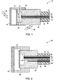
- FIG. 1 illustrates an arc flash sensor according to an embodiment of the invention.
- the sensor 10 includes a diaphragm 12 disposed near one end 13 of an optical fiber 14 having a fiber core 16 and a fiber cladding 18.
- the diaphragm 12 is configured to vibrate upon incidence of sound (acoustic waves) from an arc flash and reflect light from a laser beam 30 into the fiber core 16.
- acoustic waves may include pressure waves as well.
- the diaphragm comprises opaque material made of thin film and disposed in an elongated position.
- the diaphragm comprises a semi-transparent material.
- the semi-transparent material may include for example, a thin film that has been prestrained to respond to external air pressure dynamics and allow light transmission of about 30% to about 60%.
- the diaphragms comprises a metalized polymeric material. During fabrication of the diaphragm, metalized thin film deposition on the polymer film may be controlled to achieve desired thickness.
- diaphragm 12 may be enclosed within a protective sleeve 22 and a protective screen 24 that permits the acoustic waves from the external environment to reach the diaphragm.
- a fiber holder 20 is disposed around the optical fiber 14.
- the fiber holder includes a semi-transparent region configured to diffuse light originating from the arc flash into the fiber core 16.
- One or more optional holes 25 measuring about 0.5 mm to about 2 mm in diameter may be provided to enhance the light detection from arc flash.
- arc flash generated light is directed through the optional hole 25 towards fiber 14.
- light from an arc flash may additionally be directed towards fiber 14 through the protective screen and the diaphragm.
- the senor 10 is configured to receive acoustic waves 28 and light 26 from an arc flash.
- the sensor 10 is configured to obtain signals representative of acoustic wave and light simultaneously.
- Fiber core 16 is configured to direct laser beam 30 on the diaphragm 12.
- Diaphragm 12 is configured to vibrate based on the intensity and frequency of acoustic waves from the arc flash. Based on the vibrations, a unique pattern of light is reflected from the diaphragm in the direction of beam 31. Simultaneously, light originating from the arc flash is incident on the semi-transparent region 20.
- the semi-transparent region 20 is configured to diffuse light towards the fiber core 16.
- the semi-transparent region 20 is configured to diffuse light is at ultraviolet wavelengths.
- the distance between one end 13 of the optical fiber and the diaphragm 12 is optimized such that the reflected beam from the diaphragm 12 reaches the fiber core 16 without significant transmission losses.
- FIG. 2 illustrates an arc flash sensor according to another embodiment of the invention.
- the sensor 34 illustrates a dual fiber core design comprising two optical fibers 14, 36 having corresponding fiber cores 16, 38.
- One end 13 of the first optical fiber 14 is disposed proximate to the diaphragm 12.
- acoustic wave originating form the arc flash generate vibrations in the diaphragm.
- Reflected beam 31 captures such vibrations that are further processed to detect an arc flash.
- One end 40 of the second optical fiber 36 is disposed within the semi-transparent region 20 such that optical fiber 36 is configured to transmit diffused light resulting from the arc flash.
- optical fibers 14, 36 there are two optical fibers 14, 36 with first optical fiber 14 dedicated for acoustic wave detection and the second optical fiber 36 for light detection.
- fiber core 16 is configured for both directing the laser beam 30 on the diaphragm 12 and transmitting back the reflected beam 31 from the diaphragm 12 for further processing.
- cladding 41 around the end 40 of the optical fiber 36 is removed to increase light coupling efficiency.
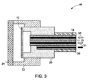
- FIG. 3 illustrates an arc flash sensor according to another embodiment of the invention.
- Sensor 44 includes three optical fibers 14, 15, 36 arranged in a manner that first optical fiber 14 is configured to transmit laser beam 30 onto the diaphragm 12 and second optical fiber 15 is configured to receive the reflected beam 31 from the diaphragm 12.
- Third optical fiber 36 as described in FIG. 2 is configured to detect light from the arc flash.
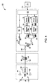
- FIG. 4 is a block diagram of an arc detection system according to an embodiment of the invention.
- the detection system 50 includes a sensor 52 coupled to an optical fiber cable 14.
- a light source 56 is coupled to the optical fiber cable 14 via an isolator 58 and a fiber splitter 60.
- the light source 56 comprises a lightemitting diode.
- the light source 56 comprises a laser diode that emits light at about near infrared wavelengths.
- a processor 62 is configured to process the combined light returning from the sensor 52 that includes reflected light 31 from the sensor and light diffused 64 through the semi-transparent region.
- the processor 62 is coupled to the fiber splitter 60 via optical filters 66, 68 and photo detectors 70, 72 and is further configured to generate an arc fault signal 73.
- the optical filters are configured to let through certain wavelength of light and to block the rest.
- Photo detectors 70, 72 are configured to generate an equivalent electrical voltage based upon the intensity and wavelength of incident light. Such electrical voltages are convenient for further processing via the processor 62.
- a protection device 74 may be coupled to the processor 62 in order to mitigate the arc flash.
- the protective device includes a protective relay configured to trip upon receiving a signal.
- the arc detection system 50 is configured to detect acoustic waves and light from an arc flash. In case of an arc flash event 48, acoustic waves 49 and light 64, among the other things, are emitted from the arc flash. Sensor 52 is configured to detect light and acoustic waves simultaneously. Sensor 52 may include any of the embodiments described in FIGs. 1-3 , for example. In one embodiment, the arc detection system 50 is adapted to implement sensor 10 having a single optical fiber 14 as discussed in FIG. 1 . Light source 56 such as a laser diode produces laser beam that is transmitted via the optical fiber to the sensor.
- Light source 56 such as a laser diode produces laser beam that is transmitted via the optical fiber to the sensor.
- Isolator 58 is disposed on the transmission end of the light source 56 such that the reflected beam 31 from the sensor and the light 64 from the arc flash are blocked from entering the laser light source 56.
- Fiber splitter 60 is configured to transmit laser beam 30 in one direction and transmit the reflected light 31 in another direction.
- the signal beam is further passed through fiber coupler 61 and then through the optical filters 66, 68.
- the optical filter 66 comprises a band-pass filter (of about 1550 nm) configured to pass light having wavelength for which the reflected beam is expected to be present to photo detector 70
- the optical filter 68 comprises a low-pass filter (of about ⁇ 700 nm) configured to pass light having wavelength for which the arc flash light is expected to be present to the photo detector 72.
- Processor 62 is configured to process the signals from both the photo detectors 70, 72 and generate an arc fault signal 73 in case of arc flash event 48.
- Protective device 74 is activated based upon the arc fault signal 73 and configured to interrupt power to mitigate the arc flash.
- FIG. 5 illustrates a block diagram of arc detection system 80 according to another embodiment of the invention.
- a lx3 fiber splitter 82 is implemented to couple the light source 56 and the photo detectors 70, 72.
- FIG. 5 is used to illustrate that the filters of FIG. 4 are not required in every embodiment.
- the photo detectors are configured to detect a particular range of wavelengths.
- photo detector 70 is configured to detect light in the range of about 1550 nanometer wavelength
- photo detector 72 is configured to detect light in the range from about 200 nanometer to about 700 nanometer wavelength.
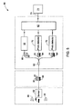
- FIG. 6 is a block diagram of arc detection system wherein at least two optical fibers are present in a sensor, such as described with respect to FIG. 2 .
- light is directed from light source through isolator 58 and coupler 90 to fiber 14 to sensor 34.
- Optical fiber 14 is configured to transmit reflected beam 31 from the diaphragm (12 as referenced in FIG. 2 ), and optical fiber 36 is configured to transmit light 64 from the arc flash.
- fiber coupler 90 is implemented to couple light source 56 and photo detector 70 to the sensor 34.
- FIG. 7 is an alternative embodiment wherein three optical fibers 14, 15, 36 (within a sensor of the type discussed with respect to FIG. 3 ) may be implemented in arc detection system 92.
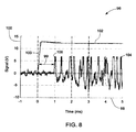
- FIG. 8 is a graph illustrating acoustic and light signals detected from an arc flash according to an embodiment of the invention.
- the graph 96 is obtained by measuring the acoustic and light signals in a simulated system having 480 V, 100 kA setup.
- the graph 96 depicts time in milliseconds on X-axis 98 and voltage on Y-axis 100.
- the profile 102 depicts the light component of the arc flash whereas profile 104 depicts the acoustic component of the arc flash.
- Relative time delay 99 between the detected arc flash induced light 103 and acoustic waves 106 serves as an unique signature.
- such relative time delay is in the order of about 0.5 ms to about 10 ms.
- Such a combination of profiles 102, 104 that form a unique pattern for a given system may be stored for future comparison. Using both acoustic and light data, and their relative time sequence is expected to mitigate the possibility of false alarm, and provide the location of arc flash event.
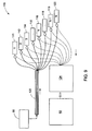
- FIG. 9 illustrates an electrical distribution system implementing arc flash sensors according to an embodiment of the invention.
- Electrical distribution system 110 includes a plurality of sensors 111-120 disposed around the system and configured to detect arc flash events. The sensors may include any design as discussed in FIGs. 1-3 .
- Light source 56 is coupled to optical fiber cable 122 and a plurality of sensors 111-120. Each sensor is coupled to photo detector array 124 via fiber couplers.
- a processor 62 is configured to generate an arc fault signal in case an arc fault is detected within the electrical distribution system. In one embodiment, processor 62 is configured to detect a location of the arc flash within the electrical distribution system based upon the signals from the plurality of sensors disposed around the distribution system.
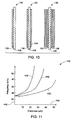
- FIG 10 illustrates several embodiments of the diaphragm implemented in an arc flash sensor according to an embodiment of the invention.
- the diaphragm 12 ( FIG. 1 ) includes polymer film with metal film deposition as indicated by the reference numeral 126.
- a single layer of thin metal film 130 (about 5nm to about 30 nm in thickness) is deposited on one side of the polymer film 128.
- reference numeral 132 illustrates at least two layers of thin metal films 130, 134 deposited on each side of the polymer film 128.
- reference numeral 136 illustrates the deposition of multiple layers of thin metal films 137, 138 deposited on one or both sides of the polymer film 128.
- the thickness of thin metal film or films controls the light transmission ratio and the frequency responses of the diaphragm with respect to acoustic waves.
- FIG. 11 illustrates frequency responses for the diaphragms in FIG. 10 .
- Graph 142 illustrates frequency measured in kHz on the Y-axis 146 and thickness measured in micrometers on X-axis 144.
- Profiles 148-152 are obtained from simulation.
- Profile 152 is an exemplary frequency response for a diaphragm configured to comprise a polymer film only.
- Profile 150 illustrates an exemplary frequency response for a diaphragm comprising thin metal film on both sides of the polymer film (132 in FIG. 10 ).
- Profile 148 illustrates an exemplary frequency response for a diaphragm comprising multilayer thin metal film on both sides of the polymer film (136 in FIG. 10 ).
- sensors as proposed in various embodiments of the invention may utilize low cost material and simple manufacture techniques. Further, such sensors have fast response and high sensitivity. Integrated sensors simultaneously detect radiation such as light and dynamic acoustic wave signals. Such integrated sensors enable fast detection of arc flash events. Optical fibers implemented for arc detection have advantages such as immunity to electromagnetic interference, reduced size and weight, distribution capability, and no additional power requirement. As used herein, the terms “a” and “an” do not denote a limitation of quantity, but rather denote the presence of at least one of the referenced item.
Landscapes
- Measurement Of Mechanical Vibrations Or Ultrasonic Waves (AREA)
- Electrostatic, Electromagnetic, Magneto- Strictive, And Variable-Resistance Transducers (AREA)
- Gas-Insulated Switchgears (AREA)
- Testing Of Short-Circuits, Discontinuities, Leakage, Or Incorrect Line Connections (AREA)
- Investigating Or Analyzing Materials By The Use Of Ultrasonic Waves (AREA)
Description
- The invention relates generally to arc flash detection and, in particular, to arc flash sensors.
- Electric power circuits and switchgear equipment have conductors separated by insulation. Air space often serves as part or all of this insulation in some applications. If the conductors are too close to each other or voltage exceeds the insulation level, an arc can occur between conductors. Air or any other insulation (gas, solid, or liquid) between conductors can become ionized, making the insulation conductive and thereby enabling an arcing event. Arc events may induce temperatures that can reach as high as 20,000° C, vaporize conductors and adjacent materials, and release an explosive energy that destroys surrounding circuits.
- An arc flash is typically the result of a rapid energy release due to an arcing fault between two phases or between one phase and a neutral or ground. An arc flash can produce high heat, intense light, and acoustic waves similar to that of an explosion. However, an arc fault current typically includes a much lower magnitude as compared to a short circuit current, and circuit breakers do not necessarily react to such lower magnitudes of current. Typically, arc flash mitigation techniques use standard fuses and circuit breakers. However, such techniques have slow response times and are not fast enough to mitigate an arc flash.
- One technique to mitigate arc faults is to reduce the response time of arc sensors. For example, reduced response time may be achieved by detecting specific characteristics of the arcing event such as light. Optical sensors detect light within an enclosure and determine the occurrence of the arc flash event. However, such a method of light detection may lead to erroneous arc detection when stray light or light from other sources is detected. Further, such methods do not provide information regarding the location of the arcing event. Other techniques include implementing pressure sensors within the enclosure to detect arc flash induced pressure changes. Such methods, however, result in delayed detection as pressure build-up takes a significant amount of time.
-
US 2007/014060 describes a sensor for detecting arcing faults, the sensor combining a photodetector, a pressure detector, and an accelerometer along with integrated circuitry. The circuitry controls each detector, operates the self-test circuitry, conditions the signals from the detectors, and communicates with the external network. The circuitry receives commands from the network and transmits the output decision from the sensor. -
US 2008/075404 describes a fiber optic sensor comprising a vibrating diaphragm, a single mode optic fiber having an endface and a Fabry-Perot type cavity between the diaphragm and the endface, wherein the sensor is adapted for detecting an on-line acoustic signature of sparking and arcing in a multitude of applications. -
WO 2010/147832 describes An apparatus to detect arc is presented. The apparatus includes a fiber sensor to detect characteristics of an arc flash and a processor to process at least two characteristics of the arc flash. The processor is further configured to generate an arc fault signal. A protective device is configured to mitigate the arc flash based on the arc fault signal. - There is a need for improved arc flash prevention mechanism that has an improved response time and minimizes false alarms.
- The invention resides in a sensor to simultaneously detect light and acoustic waves and in a method as recited in the appended claims.
- These and other features, aspects, and advantages of the present invention will become better understood when the following detailed description is read with reference to the accompanying drawings in which like characters represent like parts throughout the drawings, wherein:
-
FIG. 1 illustrates an arc flash sensor according to one embodiment of the invention; -
FIG. 2 illustrates an arc flash sensor according to another embodiment of the invention; -
FIG. 3 illustrates an arc flash sensor according to another embodiment of the invention; -
FIG. 4 is a block diagram of an arc detection system according to one embodiment of the invention; -
FIG. 5 is a block diagram of arc detection system according to another embodiment of the invention; -
FIGs. 6 is a block diagram of another arc detection system; -
FIG. 7 is a block diagram of another arc detection system; -
FIG. 8 is a graph of acoustic and light signals detected from an arc flash over time according to an embodiment of the invention; -
FIG. 9 illustrates an electrical distribution system implementing arc sensors according to one embodiment of the invention; -
FIG 10 illustrates several embodiments of the diaphragm implemented in arc flash sensors; and -
FIG. 11 illustrates frequency response for the diaphragms inFIG. 10 . -
FIG. 1 illustrates an arc flash sensor according to an embodiment of the invention. Thesensor 10 includes adiaphragm 12 disposed near oneend 13 of anoptical fiber 14 having afiber core 16 and afiber cladding 18. In one embodiment, thediaphragm 12 is configured to vibrate upon incidence of sound (acoustic waves) from an arc flash and reflect light from alaser beam 30 into thefiber core 16. As used herein, acoustic waves may include pressure waves as well. In one embodiment, the diaphragm comprises opaque material made of thin film and disposed in an elongated position. In another embodiment, the diaphragm comprises a semi-transparent material. The semi-transparent material may include for example, a thin film that has been prestrained to respond to external air pressure dynamics and allow light transmission of about 30% to about 60%. In one embodiment, to avoid saturation of photo detectors or detector arrays, the diaphragms comprises a metalized polymeric material. During fabrication of the diaphragm, metalized thin film deposition on the polymer film may be controlled to achieve desired thickness. - To provide protection for the diaphragm during operation while still allowing acoustic waves to be detected,
diaphragm 12 may be enclosed within aprotective sleeve 22 and aprotective screen 24 that permits the acoustic waves from the external environment to reach the diaphragm. Afiber holder 20 is disposed around theoptical fiber 14. In one embodiment, the fiber holder includes a semi-transparent region configured to diffuse light originating from the arc flash into thefiber core 16. One or moreoptional holes 25 measuring about 0.5 mm to about 2 mm in diameter may be provided to enhance the light detection from arc flash. In this embodiment, arc flash generated light is directed through theoptional hole 25 towardsfiber 14. In embodiments wherein theprotective screen 24 anddiaphragm 12 permit some amount of light to pass, light from an arc flash may additionally be directed towardsfiber 14 through the protective screen and the diaphragm. - In an exemplary operation, the
sensor 10 is configured to receiveacoustic waves 28 andlight 26 from an arc flash. Thesensor 10 is configured to obtain signals representative of acoustic wave and light simultaneously. Such an integrated approach of sensing acoustic wave and light simultaneously minimizes false alarms and enables early arc flash detection.Fiber core 16 is configured todirect laser beam 30 on thediaphragm 12.Diaphragm 12 is configured to vibrate based on the intensity and frequency of acoustic waves from the arc flash. Based on the vibrations, a unique pattern of light is reflected from the diaphragm in the direction ofbeam 31. Simultaneously, light originating from the arc flash is incident on thesemi-transparent region 20. Thesemi-transparent region 20 is configured to diffuse light towards thefiber core 16. In one embodiment, thesemi-transparent region 20 is configured to diffuse light is at ultraviolet wavelengths. The distance between oneend 13 of the optical fiber and thediaphragm 12 is optimized such that the reflected beam from thediaphragm 12 reaches thefiber core 16 without significant transmission losses. -
FIG. 2 illustrates an arc flash sensor according to another embodiment of the invention. Thesensor 34 illustrates a dual fiber core design comprising twooptical fibers fiber cores end 13 of the firstoptical fiber 14 is disposed proximate to thediaphragm 12. In the event of arc flash, acoustic wave originating form the arc flash generate vibrations in the diaphragm.Reflected beam 31 captures such vibrations that are further processed to detect an arc flash. Oneend 40 of the secondoptical fiber 36 is disposed within thesemi-transparent region 20 such thatoptical fiber 36 is configured to transmit diffused light resulting from the arc flash. In operation, there are twooptical fibers optical fiber 14 dedicated for acoustic wave detection and the secondoptical fiber 36 for light detection. In the illustrated embodiment,fiber core 16 is configured for both directing thelaser beam 30 on thediaphragm 12 and transmitting back the reflectedbeam 31 from thediaphragm 12 for further processing. In one embodiment, cladding 41 around theend 40 of theoptical fiber 36 is removed to increase light coupling efficiency. -
FIG. 3 illustrates an arc flash sensor according to another embodiment of the invention.Sensor 44 includes threeoptical fibers optical fiber 14 is configured to transmitlaser beam 30 onto thediaphragm 12 and secondoptical fiber 15 is configured to receive the reflectedbeam 31 from thediaphragm 12. Thirdoptical fiber 36 as described inFIG. 2 , is configured to detect light from the arc flash. -
FIG. 4 is a block diagram of an arc detection system according to an embodiment of the invention. Thedetection system 50 includes asensor 52 coupled to anoptical fiber cable 14. Alight source 56 is coupled to theoptical fiber cable 14 via anisolator 58 and afiber splitter 60. In one embodiment, thelight source 56 comprises a lightemitting diode. In another embodiment, thelight source 56 comprises a laser diode that emits light at about near infrared wavelengths. Aprocessor 62 is configured to process the combined light returning from thesensor 52 that includes reflected light 31 from the sensor and light diffused 64 through the semi-transparent region. In one embodiment, theprocessor 62 is coupled to thefiber splitter 60 viaoptical filters photo detectors arc fault signal 73. The optical filters are configured to let through certain wavelength of light and to block the rest.Photo detectors processor 62. Aprotection device 74 may be coupled to theprocessor 62 in order to mitigate the arc flash. In one embodiment, the protective device includes a protective relay configured to trip upon receiving a signal. - In an exemplary operation, the
arc detection system 50 is configured to detect acoustic waves and light from an arc flash. In case of anarc flash event 48,acoustic waves 49 and light 64, among the other things, are emitted from the arc flash.Sensor 52 is configured to detect light and acoustic waves simultaneously.Sensor 52 may include any of the embodiments described inFIGs. 1-3 , for example. In one embodiment, thearc detection system 50 is adapted to implementsensor 10 having a singleoptical fiber 14 as discussed inFIG. 1 .Light source 56 such as a laser diode produces laser beam that is transmitted via the optical fiber to the sensor.Isolator 58 is disposed on the transmission end of thelight source 56 such that the reflectedbeam 31 from the sensor and the light 64 from the arc flash are blocked from entering thelaser light source 56.Fiber splitter 60 is configured to transmitlaser beam 30 in one direction and transmit the reflected light 31 in another direction. In one embodiment, the signal beam is further passed throughfiber coupler 61 and then through theoptical filters optical filter 66 comprises a band-pass filter (of about 1550 nm) configured to pass light having wavelength for which the reflected beam is expected to be present tophoto detector 70, and theoptical filter 68 comprises a low-pass filter (of about < 700 nm) configured to pass light having wavelength for which the arc flash light is expected to be present to thephoto detector 72.Processor 62 is configured to process the signals from both thephoto detectors arc fault signal 73 in case ofarc flash event 48.Protective device 74 is activated based upon thearc fault signal 73 and configured to interrupt power to mitigate the arc flash. -
FIG. 5 illustrates a block diagram ofarc detection system 80 according to another embodiment of the invention. Instead of including twoseparate couplers lx3 fiber splitter 82 is implemented to couple thelight source 56 and thephoto detectors FIG. 5 is used to illustrate that the filters ofFIG. 4 are not required in every embodiment. In the embodiment ofFIG. 5 , the photo detectors are configured to detect a particular range of wavelengths. In one example,photo detector 70 is configured to detect light in the range of about 1550 nanometer wavelength andphoto detector 72 is configured to detect light in the range from about 200 nanometer to about 700 nanometer wavelength. -
FIG. 6 is a block diagram of arc detection system wherein at least two optical fibers are present in a sensor, such as described with respect toFIG. 2 . In operation, light is directed from light source throughisolator 58 andcoupler 90 tofiber 14 tosensor 34.Optical fiber 14 is configured to transmit reflectedbeam 31 from the diaphragm (12 as referenced inFIG. 2 ), andoptical fiber 36 is configured to transmit light 64 from the arc flash. In the embodiment ofFIG. 6 ,fiber coupler 90 is implemented to couplelight source 56 andphoto detector 70 to thesensor 34.FIG. 7 is an alternative embodiment wherein threeoptical fibers FIG. 3 ) may be implemented inarc detection system 92. -
FIG. 8 is a graph illustrating acoustic and light signals detected from an arc flash according to an embodiment of the invention. In an exemplary embodiment, thegraph 96 is obtained by measuring the acoustic and light signals in a simulated system having 480 V, 100 kA setup. Thegraph 96 depicts time in milliseconds onX-axis 98 and voltage on Y-axis 100. In the illustrated embodiment, theprofile 102 depicts the light component of the arc flash whereasprofile 104 depicts the acoustic component of the arc flash.Relative time delay 99 between the detected arc flash induced light 103 andacoustic waves 106 serves as an unique signature. In the certain embodiments, such relative time delay is in the order of about 0.5 ms to about 10 ms. Such a combination ofprofiles -
FIG. 9 illustrates an electrical distribution system implementing arc flash sensors according to an embodiment of the invention.Electrical distribution system 110 includes a plurality of sensors 111-120 disposed around the system and configured to detect arc flash events. The sensors may include any design as discussed inFIGs. 1-3 .Light source 56 is coupled tooptical fiber cable 122 and a plurality of sensors 111-120. Each sensor is coupled tophoto detector array 124 via fiber couplers. Aprocessor 62 is configured to generate an arc fault signal in case an arc fault is detected within the electrical distribution system. In one embodiment,processor 62 is configured to detect a location of the arc flash within the electrical distribution system based upon the signals from the plurality of sensors disposed around the distribution system. -
FIG 10 illustrates several embodiments of the diaphragm implemented in an arc flash sensor according to an embodiment of the invention. In an exemplary embodiment the diaphragm 12 (FIG. 1 ) includes polymer film with metal film deposition as indicated by thereference numeral 126. A single layer of thin metal film 130 (about 5nm to about 30 nm in thickness) is deposited on one side of thepolymer film 128. In another embodiment,reference numeral 132 illustrates at least two layers ofthin metal films polymer film 128. In another embodiment,reference numeral 136 illustrates the deposition of multiple layers ofthin metal films polymer film 128. The thickness of thin metal film or films controls the light transmission ratio and the frequency responses of the diaphragm with respect to acoustic waves. -
FIG. 11 illustrates frequency responses for the diaphragms inFIG. 10 .Graph 142 illustrates frequency measured in kHz on the Y-axis 146 and thickness measured in micrometers onX-axis 144. Profiles 148-152 are obtained from simulation.Profile 152 is an exemplary frequency response for a diaphragm configured to comprise a polymer film only.Profile 150 illustrates an exemplary frequency response for a diaphragm comprising thin metal film on both sides of the polymer film (132 inFIG. 10 ).Profile 148 illustrates an exemplary frequency response for a diaphragm comprising multilayer thin metal film on both sides of the polymer film (136 inFIG. 10 ). - Advantageously, sensors as proposed in various embodiments of the invention may utilize low cost material and simple manufacture techniques. Further, such sensors have fast response and high sensitivity. Integrated sensors simultaneously detect radiation such as light and dynamic acoustic wave signals. Such integrated sensors enable fast detection of arc flash events. Optical fibers implemented for arc detection have advantages such as immunity to electromagnetic interference, reduced size and weight, distribution capability, and no additional power requirement. As used herein, the terms "a" and "an" do not denote a limitation of quantity, but rather denote the presence of at least one of the referenced item.
- While only certain features of the invention have been illustrated and described herein, many modifications and changes will occur to those skilled in the art.
Claims (14)
- A sensor (10) to simultaneously detect light (26) and acoustic waves (28), the sensor comprising:one or more optical fibers (14, 15, 36) ;a diaphragm (12) disposed near one end of at least one of the one or more optical fibers (14, 15, 36), the one or more optical fibers (14, 15, 36) being configured to transmit light from a light source (56) onto the diaphragm (12) and to receive a reflected light beam (31) from the diaphragm (12) and the diaphragm (12) being configured to vibrate upon incidence of acoustic waves (28) from an arc flash; anda semi-transparent region (20) disposed around the one or more optical fibers (14, 15, 36) to diffuse light (26) originating from the arc flash into at least one of the one or more optical fibers (14, 15, 36).
- The sensor of claim 1, wherein the one or more optical fibers (14, 15, 36) comprise at least one optical fiber for transmitting the arc flash-generated light (26) towards a detection system (50).
- The sensor of claim 1 or 2, wherein the one or more optical fibers comprise a first optical fiber (14) having one end near the diaphragm (12) for transmitting light (30) from the light source (56) to the diaphragm (12) and for transmitting the reflected light beam (31) from the diaphragm (12) towards a detection system (50) and a second optical fiber (36) having an end disposed within the semi-transparent region (20) for transmitting light (26) resulting from the arc flash towards the detection system(50).
- The sensor of any of the preceding claims, wherein the one or more optical fibers comprise a first optical fiber (14) having one end near the diaphragm (12) for transmitting light from a light source (56) to the diaphragm (12), a second optical fiber (15) having one end near the diaphragm (12) and for transmitting reflected light beam (31) towards a detection system, and a third optical fiber (36) having an end disposed within the semi-transparent region (20 for transmitting light resulting from the arc flash towards the detection system (50).
- The sensor of any of the preceding claims, further comprising a protective screen (24) attached to the protective sleeve (22) and configured to enable acoustic waves reach the diaphragm (12) while preventing contaminants from reaching the diaphragm (12).
- The sensor of any of the preceding claims, wherein the diaphragm (12) comprises at least one of a transparent, a semi-transparent, or an opaque material.
- An arc flash detection system comprising
the sensor (52) of any of claims 1 to 6;
one or more photo detectors (70, 72) configured to detect different wavelengths of the reflected and diffused light (31, 64); and
a processor (62) coupled to the one or more photo detectors (70, 72) and configured to generate an arc fault signal (70) on detection of an occurrence (48) of an arc flash. - The arc flash detection system of claim 7, further comprising optical filters (66) coupled between the sensor (52) and the photo detectors (70, 72), wherein the filters (66) comprise at least one of a low-pass filter and a band-pass filter coupled between the sensor (52) and the photo detectors (70, 72).
- The arc flash detection system of claims 7 or 8, further comprising a protection device (74) coupled to the processor (62), wherein the processor (62) is configured to provide the arc fault signal to the protection device (74) upon a detection of the occurrence (48) of the arc flash.
- A method comprising:transmitting light via one or more optical fibers (14, 15, 36) from a light source (56) onto a diaphragm (12);diffusing light (26) originating from an arc flash into at least one of the one or more optical fibers (14, 15, 36) by a semi-transparent region (20) disposed around the one or more optical fibers (14, 15, 36), the diaphragm (12) being configured to vibrate upon incidence of acoustic waves (49) from the arc flash;transmitting light (31) originating from said one or more optical fibers (14, 15, 36) and reflected from the diaphragm (12), and the diffused light (64) to a detector system (50) via the one or more optical fibers (14, 15, 36);filtering and processing the transmitted reflected and diffused light (31, 64) to detect an occurrence of an arc flash.
- The method of claim 10, wherein the processing comprises determining a time delay between detection of acoustic waves (49) that are indicative of an arc flash and detection of light (64) that is indicative of an arc flash.
- The method of claim 10 or 11, further comprising generating an arc fault signal (73) to mitigate the arc flash.
- The method of any of claims 10 to 12, wherein filtering comprises detecting light of a plurality of wavelengths.
- The method of any of claims 10 to 13, further comprising activating a protective device (74) upon detection of the occurrence (48) of an arc flash.
Applications Claiming Priority (1)
| Application Number | Priority Date | Filing Date | Title |
|---|---|---|---|
| US12/770,827 US8040517B1 (en) | 2010-04-30 | 2010-04-30 | Arc flash detection system and method |
Publications (3)
| Publication Number | Publication Date |
|---|---|
| EP2383855A2 EP2383855A2 (en) | 2011-11-02 |
| EP2383855A3 EP2383855A3 (en) | 2012-08-15 |
| EP2383855B1 true EP2383855B1 (en) | 2013-08-28 |
Family
ID=44359489
Family Applications (1)
| Application Number | Title | Priority Date | Filing Date |
|---|---|---|---|
| EP11164071.0A Active EP2383855B1 (en) | 2010-04-30 | 2011-04-28 | Arc flash detection system and method |
Country Status (4)
| Country | Link |
|---|---|
| US (2) | US8040517B1 (en) |
| EP (1) | EP2383855B1 (en) |
| JP (1) | JP5829831B2 (en) |
| ES (1) | ES2434026T3 (en) |
Families Citing this family (42)
| Publication number | Priority date | Publication date | Assignee | Title |
|---|---|---|---|---|
| US8319173B2 (en) | 2008-09-19 | 2012-11-27 | Schweitzer Engineering Laboratories Inc | Arc flash protection with self-test |
| WO2010033837A1 (en) * | 2008-09-19 | 2010-03-25 | Schweitzer Engineering Laboratories, Inc. | Validation of arc flash detection systems |
| EP2329575A4 (en) | 2008-09-19 | 2013-09-04 | Schweitzer Engineering Lab Inc | Protective device with metering and oscillography |
| WO2010033851A1 (en) | 2008-09-19 | 2010-03-25 | Schweitzer Engineering Laboratories, Inc. | Electro-optical radiation collector for arc flash detection |
| WO2010033830A1 (en) * | 2008-09-19 | 2010-03-25 | Schweitzer Engineering Laboratories, Inc. | Secure arc flash detection |
| US8054594B2 (en) * | 2009-06-18 | 2011-11-08 | General Electric Company | ARC flash detection system |
| US8091429B2 (en) * | 2009-08-14 | 2012-01-10 | The Johns Hopkins University | Apparatus and method for high frequency low pressure arc flash sensor |
| DE102009057130A1 (en) * | 2009-12-08 | 2011-06-09 | Heinrich-Heine-Universität Düsseldorf | Method for analyzing the composition of gas mixtures |
| US9522396B2 (en) | 2010-12-29 | 2016-12-20 | S.D. Sight Diagnostics Ltd. | Apparatus and method for automatic detection of pathogens |
| WO2013098821A1 (en) | 2011-12-29 | 2013-07-04 | Parasight Ltd. | Methods and systems for detecting a pathogen in a biological sample |
| KR101266834B1 (en) * | 2012-04-24 | 2013-05-27 | 엘에스산전 주식회사 | Digital protection relay |
| US9438028B2 (en) | 2012-08-31 | 2016-09-06 | Schweitzer Engineering Laboratories, Inc. | Motor relay with integrated arc-flash detection |
| US9413155B2 (en) * | 2013-02-19 | 2016-08-09 | Kenneth Gerald Blemel | System to protect from unsafe conditions in an electrical power system |
| US9178353B2 (en) | 2013-03-27 | 2015-11-03 | Sunfield Semiconductor, Inc. | Active bypass diode circuit and solar power module with arc flash mitigation feature |
| EP2999988A4 (en) | 2013-05-23 | 2017-01-11 | S.D. Sight Diagnostics Ltd. | Method and system for imaging a cell sample |
| IL227276A0 (en) | 2013-07-01 | 2014-03-06 | Parasight Ltd | A method and system for preparing a monolayer of cells, particularly suitable for diagnosis |
| WO2015029032A1 (en) | 2013-08-26 | 2015-03-05 | Parasight Ltd. | Digital microscopy systems, methods and computer program products |
| CN103728017B (en) * | 2014-01-17 | 2015-08-05 | 安徽大学 | Light pressure detection method of light pressure sensor based on nano silver film |
| CN106030949B (en) * | 2014-02-19 | 2020-04-14 | 管理科学有限公司 | System for protecting against unsafe conditions in an electrical power system |
| CN103822707B (en) * | 2014-03-17 | 2016-04-20 | 中国科学院大气物理研究所 | Thunder and lightning high-speed photometer |
| JP6374708B2 (en) * | 2014-05-29 | 2018-08-15 | デクセリアルズ株式会社 | Ionic liquid, lubricant and magnetic recording medium |
| WO2016030897A1 (en) | 2014-08-27 | 2016-03-03 | S.D. Sight Diagnostics Ltd | System and method for calculating focus variation for a digital microscope |
| FR3034202B1 (en) * | 2015-03-25 | 2017-04-07 | Labinal Power Systems | METHOD AND DEVICE FOR PROTECTING AN ELECTRICAL NETWORK |
| CN105137300A (en) * | 2015-08-31 | 2015-12-09 | 武汉光迅科技股份有限公司 | Inclined-angle type double-fiber arc light detection probe |
| CN105203201B (en) * | 2015-09-11 | 2018-08-10 | 中国科学院电子学研究所 | Feel cylinder record and applies its sound wave sensing probe |
| EP3859425B1 (en) | 2015-09-17 | 2024-04-17 | S.D. Sight Diagnostics Ltd. | Methods and apparatus for detecting an entity in a bodily sample |
| FR3046232B1 (en) | 2015-12-28 | 2018-02-16 | Commissariat A L'energie Atomique Et Aux Energies Alternatives | METHOD FOR DETECTING AN ELECTRIC ARC BY ANALYSIS OF ITS ACOUSTIC SIGNATURE |
| WO2017168411A1 (en) | 2016-03-30 | 2017-10-05 | S.D. Sight Diagnostics Ltd | Image processing device for identifying blood parasites |
| EP3455610B1 (en) | 2016-05-11 | 2023-01-04 | S.D. Sight Diagnostics Ltd. | Sample carrier for optical measurements |
| CN109564209B (en) | 2016-05-11 | 2022-05-31 | 思迪赛特诊断有限公司 | Optical measurements performed on samples |
| FR3053122B1 (en) * | 2016-06-27 | 2018-07-27 | Commissariat A L'energie Atomique Et Aux Energies Alternatives | DEVICE FOR DETECTING AN ELECTRIC ARC FROM ITS ACOUSTIC SIGNATURE |
| CN107560726B (en) | 2016-06-30 | 2020-01-14 | 西门子公司 | Arc sensor and arc detection method |
| US10804689B2 (en) | 2016-11-18 | 2020-10-13 | Schweitzer Engineering Laboratories, Inc. | Methods and systems for evaluating arc flash exposure hazard |
| CN111788471B (en) | 2017-11-14 | 2023-12-12 | 思迪赛特诊断有限公司 | Sample carrier for optical measurement |
| JP6954151B2 (en) * | 2018-01-25 | 2021-10-27 | 王子ホールディングス株式会社 | Analytical substrate and its manufacturing method |
| RU2715477C1 (en) * | 2019-04-30 | 2020-02-28 | федеральное государственное автономное образовательное учреждение высшего образования "Национальный исследовательский университет ИТМО" (Университет ИТМО) | Arcing sensor |
| US10916391B1 (en) | 2019-09-23 | 2021-02-09 | Glen Payne | Arc flash detection systems and components thereof |
| US11837862B2 (en) | 2020-10-09 | 2023-12-05 | Schweitzer Engineering Laboratories, Inc. | Arc-flash sensor using optical fiber |
| US11527878B2 (en) | 2020-10-14 | 2022-12-13 | Eaton Intelligent Power Limited | Hybrid arc flash mitigation system |
| US11482851B2 (en) | 2020-10-14 | 2022-10-25 | Eaton Intelligent Power Limited | Arc flash mitigation device |
| US11796584B2 (en) * | 2022-01-03 | 2023-10-24 | Xerox Corporation | Partial discharge detection system and method |
| US11411382B1 (en) | 2022-01-26 | 2022-08-09 | Arc Suppression Technologies | Arc flash suppressor, system, and method |
Family Cites Families (40)
| Publication number | Priority date | Publication date | Assignee | Title |
|---|---|---|---|---|
| GB1476527A (en) * | 1974-10-02 | 1977-06-16 | Suhl Elektrogeraete Veb K | Arrangement for detecting sparking at the brushes of electrical machines |
| DE2856188C2 (en) * | 1978-12-27 | 1985-09-05 | Brown, Boveri & Cie Ag, 6800 Mannheim | Device for the detection of arcing faults in switchgear |
| DE3129041A1 (en) * | 1981-07-23 | 1983-02-03 | BBC Aktiengesellschaft Brown, Boveri & Cie., 5401 Baden, Aargau | FIBER OPTICAL SENSOR FOR DETECTING ELECTRIC ARCH DISCHARGE |
| SE450862B (en) * | 1981-09-04 | 1987-08-03 | Asea Ab | LIGHT BAG DETECTION |
| US4539480A (en) * | 1982-11-08 | 1985-09-03 | Cibertec S.A. | Electrical isolation system |
| JPS626181A (en) * | 1985-07-02 | 1987-01-13 | Mitsubishi Electric Corp | Abnormality detection device for gas insulating apparatus |
| US4791518A (en) * | 1986-06-09 | 1988-12-13 | Bbc Brown Boveri Ag | Device for detecting interfering arcs |
| US4903248A (en) * | 1988-03-09 | 1990-02-20 | Mine Safety Appliances Company | Photo-acoustic detector |
| US4866681A (en) * | 1988-03-09 | 1989-09-12 | Mine Safety Appliances Company | Photo-acoustic detector |
| FR2632066B1 (en) * | 1988-05-24 | 1990-08-10 | Lyonnaise Transmiss Optiques | DEVICE FOR MEASURING THE ENERGY OF AN ELECTRIC ARC |
| US4940933A (en) * | 1989-04-13 | 1990-07-10 | Westinghouse Electric Corp. | Fiber optic arc monitor |
| FR2658920B1 (en) * | 1990-02-26 | 1992-07-03 | Merlin Gerin | DEVICE FOR DETECTING AN INTERNAL ARC IN AN ARMORED ELECTRICAL INSTALLATION. |
| JPH04118893A (en) * | 1990-09-07 | 1992-04-20 | Matsushita Electric Ind Co Ltd | Discharge lamp lighting device |
| JPH0455583U (en) * | 1990-09-20 | 1992-05-13 | ||
| US5125749A (en) * | 1990-09-24 | 1992-06-30 | The Dow Chemical Company | Probe for photoacoustic analysis |
| US5185686A (en) * | 1991-03-28 | 1993-02-09 | Eaton Corporation | Direction sensing arc detection |
| JPH0759221A (en) * | 1993-08-11 | 1995-03-03 | Meidensha Corp | Abnormality detector for gas insulated power equipment |
| US6313641B1 (en) * | 1995-03-13 | 2001-11-06 | Square D Company | Method and system for detecting arcing faults and testing such system |
| US5940547A (en) * | 1995-03-30 | 1999-08-17 | Klockner-Moeller Gmbh | Optical fiber accidental arc detector for an electric power distribution switching device |
| US6037857A (en) * | 1997-06-06 | 2000-03-14 | Allen-Bradley Company, Llc | Serial data isolator industrial control system providing intrinsically safe operation |
| US5933308A (en) * | 1997-11-19 | 1999-08-03 | Square D Company | Arcing fault protection system for a switchgear enclosure |
| US6772077B1 (en) * | 1998-08-10 | 2004-08-03 | Hendry Mechanical Works | Electric arc monitoring systems |
| FR2783348B1 (en) * | 1998-09-15 | 2000-10-13 | Alstom Technology | METHOD OF DISCRIMINATION BETWEEN AN INTERNAL ARC AND A CUT-OUT ARC IN A MEDIUM OR HIGH VOLTAGE CIRCUIT BREAKER |
| JP2000346705A (en) * | 1999-06-09 | 2000-12-15 | Nissin Electric Co Ltd | Arc light detector |
| US6229680B1 (en) * | 1999-08-16 | 2001-05-08 | Eaton Corporation | Apparatus and method for optically detecting arcing faults in electric power systems in the presence of other light sources |
| US6433976B1 (en) * | 1999-09-24 | 2002-08-13 | Square D Company | Instantaneous arc fault light detector with resistance to false tripping |
| US6693438B2 (en) * | 2002-02-12 | 2004-02-17 | Eaton Corporation | Self-powered apparatus and method for optically detecting arcing faults in electric power systems in the presence of other light sources |
| US6734682B2 (en) | 2002-03-05 | 2004-05-11 | Eaton Corporation | Testing device for detecting and locating arc faults in an electrical system |
| US6903357B2 (en) * | 2002-10-28 | 2005-06-07 | The Boeing Company | Solid state spark detection |
| DE10342370B3 (en) * | 2003-09-09 | 2005-04-28 | Fachhochschule Nordhausen | Arrangement for monitoring electrical devices for the generation of arcing faults |
| US7035068B2 (en) * | 2003-12-05 | 2006-04-25 | Eaton Corporation | Apparatus and method employing an optical fiber for closed-loop feedback detection of arcing faults |
| US7148696B2 (en) | 2005-01-12 | 2006-12-12 | Eaton Corporation | Electrical switching apparatus and method including fault detection employing acoustic signature |
| US7536914B2 (en) * | 2005-07-18 | 2009-05-26 | The Johns Hopkins University | Sensor for detecting arcing faults |
| US7403129B2 (en) | 2006-05-10 | 2008-07-22 | Eaton Corporation | Electrical switching apparatus and method employing acoustic and current signals to distinguish between parallel and series arc faults |
| WO2007136779A2 (en) * | 2006-05-19 | 2007-11-29 | New Jersey Institute Of Technology | Aligned embossed diaphgragm based fiber optic sensor |
| JP2008032587A (en) * | 2006-07-31 | 2008-02-14 | Meidensha Corp | Ae sensor using interference-type optical fiber, and partial discharge measuring device by ae sensor |
| JP4308247B2 (en) * | 2006-12-25 | 2009-08-05 | サンテック株式会社 | Optical fiber sensor system |
| US7499251B2 (en) * | 2007-01-11 | 2009-03-03 | Eldridge R Byron | Arcing fault protection system for an air arc switchgear enclosure |
| US8342005B2 (en) * | 2008-12-01 | 2013-01-01 | Lawrence Livermore National Security, Llc | Micro-optical-mechanical system photoacoustic spectrometer |
| US8054594B2 (en) * | 2009-06-18 | 2011-11-08 | General Electric Company | ARC flash detection system |
-
2010
- 2010-04-30 US US12/770,827 patent/US8040517B1/en active Active
-
2011
- 2011-04-20 JP JP2011093576A patent/JP5829831B2/en active Active
- 2011-04-28 EP EP11164071.0A patent/EP2383855B1/en active Active
- 2011-04-28 ES ES11164071T patent/ES2434026T3/en active Active
- 2011-09-15 US US13/233,212 patent/US8154730B2/en active Active
Also Published As
| Publication number | Publication date |
|---|---|
| ES2434026T3 (en) | 2013-12-13 |
| EP2383855A2 (en) | 2011-11-02 |
| EP2383855A3 (en) | 2012-08-15 |
| JP2011237422A (en) | 2011-11-24 |
| JP5829831B2 (en) | 2015-12-09 |
| US20120002195A1 (en) | 2012-01-05 |
| US8154730B2 (en) | 2012-04-10 |
| US20110267620A1 (en) | 2011-11-03 |
| US8040517B1 (en) | 2011-10-18 |
Similar Documents
| Publication | Publication Date | Title |
|---|---|---|
| EP2383855B1 (en) | Arc flash detection system and method | |
| JP5571782B2 (en) | Arc flash detection system | |
| EP1335466B1 (en) | Self-powered apparatus and method for optically detecting arcing faults in electric power systems in the presence of other light sources | |
| US7580232B2 (en) | Arc detection system and method | |
| US10215793B2 (en) | Fiber aligned and motionally coupled with electric cable | |
| KR101936038B1 (en) | Methods, systems, and apparatus for detecting light and acoustic waves | |
| EP2329576B1 (en) | Electro-optical radiation collector for arc flash detection | |
| Parikh et al. | A novel approach for arc-flash detection and mitigation: At the speed of light and sound | |
| JP2015523551A (en) | Radiation detector | |
| KR102066535B1 (en) | Partial discharge detection system using optical fiber ultrasonic sensor in high voltage power system | |
| JPS6217693B2 (en) | ||
| KR102026452B1 (en) | Apparatus for detecting area of arc in electrical equipment | |
| WO2002021657A1 (en) | Fiber optic light sensor system | |
| KR102066534B1 (en) | System for detecting arc flash in distribution board | |
| CN109709453B (en) | Ultraviolet light ultrasonic wave composite arc discharge detection system | |
| Yin et al. | An all-fiber partial discharge monitoring system based on both intrinsic fiber optic interferometry sensor and fluorescent fiber | |
| US10254159B2 (en) | Power limiting methods for use with optical systems in hazardous area locations | |
| JPH08201224A (en) | Ultraviolet light source failure detection system | |
| KR20220121037A (en) | Arc Detecting Apparatus | |
| CN118641907A (en) | Transformer partial discharge measurement system | |
| JPS59208691A (en) | Fire detection system using optical fiber |
Legal Events
| Date | Code | Title | Description |
|---|---|---|---|
| AK | Designated contracting states |
Kind code of ref document: A2 Designated state(s): AL AT BE BG CH CY CZ DE DK EE ES FI FR GB GR HR HU IE IS IT LI LT LU LV MC MK MT NL NO PL PT RO RS SE SI SK SM TR |
|
| AX | Request for extension of the european patent |
Extension state: BA ME |
|
| RIN1 | Information on inventor provided before grant (corrected) |
Inventor name: CHEN, QIN Inventor name: WU, JUNTAO Inventor name: ALLCOCK, DAVID JOHN Inventor name: XIA, HUA Inventor name: MAO, ZHIHONG Inventor name: DEVEAUX, ROBERT |
|
| PUAI | Public reference made under article 153(3) epc to a published international application that has entered the european phase |
Free format text: ORIGINAL CODE: 0009012 |
|
| PUAL | Search report despatched |
Free format text: ORIGINAL CODE: 0009013 |
|
| AK | Designated contracting states |
Kind code of ref document: A3 Designated state(s): AL AT BE BG CH CY CZ DE DK EE ES FI FR GB GR HR HU IE IS IT LI LT LU LV MC MK MT NL NO PL PT RO RS SE SI SK SM TR |
|
| AX | Request for extension of the european patent |
Extension state: BA ME |
|
| RIC1 | Information provided on ipc code assigned before grant |
Ipc: H02H 1/00 20060101AFI20120706BHEP |
|
| GRAP | Despatch of communication of intention to grant a patent |
Free format text: ORIGINAL CODE: EPIDOSNIGR1 |
|
| 17P | Request for examination filed |
Effective date: 20130215 |
|
| GRAS | Grant fee paid |
Free format text: ORIGINAL CODE: EPIDOSNIGR3 |
|
| GRAA | (expected) grant |
Free format text: ORIGINAL CODE: 0009210 |
|
| AK | Designated contracting states |
Kind code of ref document: B1 Designated state(s): AL AT BE BG CH CY CZ DE DK EE ES FI FR GB GR HR HU IE IS IT LI LT LU LV MC MK MT NL NO PL PT RO RS SE SI SK SM TR |
|
| REG | Reference to a national code |
Ref country code: GB Ref legal event code: FG4D |
|
| REG | Reference to a national code |
Ref country code: CH Ref legal event code: EP |
|
| REG | Reference to a national code |
Ref country code: AT Ref legal event code: REF Ref document number: 629786 Country of ref document: AT Kind code of ref document: T Effective date: 20130915 |
|
| REG | Reference to a national code |
Ref country code: IE Ref legal event code: FG4D |
|
| REG | Reference to a national code |
Ref country code: DE Ref legal event code: R096 Ref document number: 602011002785 Country of ref document: DE Effective date: 20131024 |
|
| REG | Reference to a national code |
Ref country code: ES Ref legal event code: FG2A Ref document number: 2434026 Country of ref document: ES Kind code of ref document: T3 Effective date: 20131213 |
|
| REG | Reference to a national code |
Ref country code: AT Ref legal event code: MK05 Ref document number: 629786 Country of ref document: AT Kind code of ref document: T Effective date: 20130828 |
|
| REG | Reference to a national code |
Ref country code: LT Ref legal event code: MG4D |
|
| REG | Reference to a national code |
Ref country code: NL Ref legal event code: VDEP Effective date: 20130828 |
|
| PG25 | Lapsed in a contracting state [announced via postgrant information from national office to epo] |
Ref country code: LT Free format text: LAPSE BECAUSE OF FAILURE TO SUBMIT A TRANSLATION OF THE DESCRIPTION OR TO PAY THE FEE WITHIN THE PRESCRIBED TIME-LIMIT Effective date: 20130828 Ref country code: PT Free format text: LAPSE BECAUSE OF FAILURE TO SUBMIT A TRANSLATION OF THE DESCRIPTION OR TO PAY THE FEE WITHIN THE PRESCRIBED TIME-LIMIT Effective date: 20131230 Ref country code: CY Free format text: LAPSE BECAUSE OF FAILURE TO SUBMIT A TRANSLATION OF THE DESCRIPTION OR TO PAY THE FEE WITHIN THE PRESCRIBED TIME-LIMIT Effective date: 20130724 Ref country code: SE Free format text: LAPSE BECAUSE OF FAILURE TO SUBMIT A TRANSLATION OF THE DESCRIPTION OR TO PAY THE FEE WITHIN THE PRESCRIBED TIME-LIMIT Effective date: 20130828 Ref country code: NO Free format text: LAPSE BECAUSE OF FAILURE TO SUBMIT A TRANSLATION OF THE DESCRIPTION OR TO PAY THE FEE WITHIN THE PRESCRIBED TIME-LIMIT Effective date: 20131128 Ref country code: HR Free format text: LAPSE BECAUSE OF FAILURE TO SUBMIT A TRANSLATION OF THE DESCRIPTION OR TO PAY THE FEE WITHIN THE PRESCRIBED TIME-LIMIT Effective date: 20130828 Ref country code: AT Free format text: LAPSE BECAUSE OF FAILURE TO SUBMIT A TRANSLATION OF THE DESCRIPTION OR TO PAY THE FEE WITHIN THE PRESCRIBED TIME-LIMIT Effective date: 20130828 Ref country code: IS Free format text: LAPSE BECAUSE OF FAILURE TO SUBMIT A TRANSLATION OF THE DESCRIPTION OR TO PAY THE FEE WITHIN THE PRESCRIBED TIME-LIMIT Effective date: 20131228 |
|
| REG | Reference to a national code |
Ref country code: NL Ref legal event code: VDEP Effective date: 20130828 |
|
| PG25 | Lapsed in a contracting state [announced via postgrant information from national office to epo] |
Ref country code: PL Free format text: LAPSE BECAUSE OF FAILURE TO SUBMIT A TRANSLATION OF THE DESCRIPTION OR TO PAY THE FEE WITHIN THE PRESCRIBED TIME-LIMIT Effective date: 20130828 Ref country code: LV Free format text: LAPSE BECAUSE OF FAILURE TO SUBMIT A TRANSLATION OF THE DESCRIPTION OR TO PAY THE FEE WITHIN THE PRESCRIBED TIME-LIMIT Effective date: 20130828 Ref country code: SI Free format text: LAPSE BECAUSE OF FAILURE TO SUBMIT A TRANSLATION OF THE DESCRIPTION OR TO PAY THE FEE WITHIN THE PRESCRIBED TIME-LIMIT Effective date: 20130828 Ref country code: GR Free format text: LAPSE BECAUSE OF FAILURE TO SUBMIT A TRANSLATION OF THE DESCRIPTION OR TO PAY THE FEE WITHIN THE PRESCRIBED TIME-LIMIT Effective date: 20131129 Ref country code: BE Free format text: LAPSE BECAUSE OF FAILURE TO SUBMIT A TRANSLATION OF THE DESCRIPTION OR TO PAY THE FEE WITHIN THE PRESCRIBED TIME-LIMIT Effective date: 20130828 |
|
| PG25 | Lapsed in a contracting state [announced via postgrant information from national office to epo] |
Ref country code: CY Free format text: LAPSE BECAUSE OF FAILURE TO SUBMIT A TRANSLATION OF THE DESCRIPTION OR TO PAY THE FEE WITHIN THE PRESCRIBED TIME-LIMIT Effective date: 20130828 |
|
| PG25 | Lapsed in a contracting state [announced via postgrant information from national office to epo] |
Ref country code: NL Free format text: LAPSE BECAUSE OF FAILURE TO SUBMIT A TRANSLATION OF THE DESCRIPTION OR TO PAY THE FEE WITHIN THE PRESCRIBED TIME-LIMIT Effective date: 20130828 Ref country code: SK Free format text: LAPSE BECAUSE OF FAILURE TO SUBMIT A TRANSLATION OF THE DESCRIPTION OR TO PAY THE FEE WITHIN THE PRESCRIBED TIME-LIMIT Effective date: 20130828 Ref country code: EE Free format text: LAPSE BECAUSE OF FAILURE TO SUBMIT A TRANSLATION OF THE DESCRIPTION OR TO PAY THE FEE WITHIN THE PRESCRIBED TIME-LIMIT Effective date: 20130828 Ref country code: RO Free format text: LAPSE BECAUSE OF FAILURE TO SUBMIT A TRANSLATION OF THE DESCRIPTION OR TO PAY THE FEE WITHIN THE PRESCRIBED TIME-LIMIT Effective date: 20130828 Ref country code: CZ Free format text: LAPSE BECAUSE OF FAILURE TO SUBMIT A TRANSLATION OF THE DESCRIPTION OR TO PAY THE FEE WITHIN THE PRESCRIBED TIME-LIMIT Effective date: 20130828 Ref country code: DK Free format text: LAPSE BECAUSE OF FAILURE TO SUBMIT A TRANSLATION OF THE DESCRIPTION OR TO PAY THE FEE WITHIN THE PRESCRIBED TIME-LIMIT Effective date: 20130828 |
|
| PG25 | Lapsed in a contracting state [announced via postgrant information from national office to epo] |
Ref country code: IT Free format text: LAPSE BECAUSE OF FAILURE TO SUBMIT A TRANSLATION OF THE DESCRIPTION OR TO PAY THE FEE WITHIN THE PRESCRIBED TIME-LIMIT Effective date: 20130828 |
|
| REG | Reference to a national code |
Ref country code: DE Ref legal event code: R097 Ref document number: 602011002785 Country of ref document: DE |
|
| PLBE | No opposition filed within time limit |
Free format text: ORIGINAL CODE: 0009261 |
|
| STAA | Information on the status of an ep patent application or granted ep patent |
Free format text: STATUS: NO OPPOSITION FILED WITHIN TIME LIMIT |
|
| 26N | No opposition filed |
Effective date: 20140530 |
|
| REG | Reference to a national code |
Ref country code: DE Ref legal event code: R097 Ref document number: 602011002785 Country of ref document: DE Effective date: 20140530 |
|
| PG25 | Lapsed in a contracting state [announced via postgrant information from national office to epo] |
Ref country code: MC Free format text: LAPSE BECAUSE OF FAILURE TO SUBMIT A TRANSLATION OF THE DESCRIPTION OR TO PAY THE FEE WITHIN THE PRESCRIBED TIME-LIMIT Effective date: 20130828 Ref country code: LU Free format text: LAPSE BECAUSE OF FAILURE TO SUBMIT A TRANSLATION OF THE DESCRIPTION OR TO PAY THE FEE WITHIN THE PRESCRIBED TIME-LIMIT Effective date: 20140428 |
|
| REG | Reference to a national code |
Ref country code: IE Ref legal event code: MM4A |
|
| PG25 | Lapsed in a contracting state [announced via postgrant information from national office to epo] |
Ref country code: IE Free format text: LAPSE BECAUSE OF NON-PAYMENT OF DUE FEES Effective date: 20140428 |
|
| PG25 | Lapsed in a contracting state [announced via postgrant information from national office to epo] |
Ref country code: MT Free format text: LAPSE BECAUSE OF FAILURE TO SUBMIT A TRANSLATION OF THE DESCRIPTION OR TO PAY THE FEE WITHIN THE PRESCRIBED TIME-LIMIT Effective date: 20130828 |
|
| REG | Reference to a national code |
Ref country code: FR Ref legal event code: PLFP Year of fee payment: 6 |
|
| PG25 | Lapsed in a contracting state [announced via postgrant information from national office to epo] |
Ref country code: SM Free format text: LAPSE BECAUSE OF FAILURE TO SUBMIT A TRANSLATION OF THE DESCRIPTION OR TO PAY THE FEE WITHIN THE PRESCRIBED TIME-LIMIT Effective date: 20130828 |
|
| PG25 | Lapsed in a contracting state [announced via postgrant information from national office to epo] |
Ref country code: RS Free format text: LAPSE BECAUSE OF NON-PAYMENT OF DUE FEES Effective date: 20130828 Ref country code: BG Free format text: LAPSE BECAUSE OF FAILURE TO SUBMIT A TRANSLATION OF THE DESCRIPTION OR TO PAY THE FEE WITHIN THE PRESCRIBED TIME-LIMIT Effective date: 20130828 |
|
| PG25 | Lapsed in a contracting state [announced via postgrant information from national office to epo] |
Ref country code: HU Free format text: LAPSE BECAUSE OF FAILURE TO SUBMIT A TRANSLATION OF THE DESCRIPTION OR TO PAY THE FEE WITHIN THE PRESCRIBED TIME-LIMIT; INVALID AB INITIO Effective date: 20110428 Ref country code: TR Free format text: LAPSE BECAUSE OF FAILURE TO SUBMIT A TRANSLATION OF THE DESCRIPTION OR TO PAY THE FEE WITHIN THE PRESCRIBED TIME-LIMIT Effective date: 20130828 |
|
| REG | Reference to a national code |
Ref country code: FR Ref legal event code: PLFP Year of fee payment: 7 |
|
| REG | Reference to a national code |
Ref country code: FR Ref legal event code: PLFP Year of fee payment: 8 |
|
| PG25 | Lapsed in a contracting state [announced via postgrant information from national office to epo] |
Ref country code: MK Free format text: LAPSE BECAUSE OF FAILURE TO SUBMIT A TRANSLATION OF THE DESCRIPTION OR TO PAY THE FEE WITHIN THE PRESCRIBED TIME-LIMIT Effective date: 20130828 |
|
| PGFP | Annual fee paid to national office [announced via postgrant information from national office to epo] |
Ref country code: CH Payment date: 20180502 Year of fee payment: 8 |
|
| PG25 | Lapsed in a contracting state [announced via postgrant information from national office to epo] |
Ref country code: AL Free format text: LAPSE BECAUSE OF FAILURE TO SUBMIT A TRANSLATION OF THE DESCRIPTION OR TO PAY THE FEE WITHIN THE PRESCRIBED TIME-LIMIT Effective date: 20130828 |
|
| REG | Reference to a national code |
Ref country code: CH Ref legal event code: PL |
|
| PG25 | Lapsed in a contracting state [announced via postgrant information from national office to epo] |
Ref country code: CH Free format text: LAPSE BECAUSE OF NON-PAYMENT OF DUE FEES Effective date: 20190430 Ref country code: LI Free format text: LAPSE BECAUSE OF NON-PAYMENT OF DUE FEES Effective date: 20190430 |
|
| P01 | Opt-out of the competence of the unified patent court (upc) registered |
Effective date: 20230522 |
|
| REG | Reference to a national code |
Ref country code: DE Ref legal event code: R081 Ref document number: 602011002785 Country of ref document: DE Owner name: GENERAL ELECTRIC TECHNOLOGY GMBH, CH Free format text: FORMER OWNER: GENERAL ELECTRIC COMPANY, SCHENECTADY, NY, US |
|
| REG | Reference to a national code |
Ref country code: GB Ref legal event code: 732E Free format text: REGISTERED BETWEEN 20240222 AND 20240228 |
|
| PGFP | Annual fee paid to national office [announced via postgrant information from national office to epo] |
Ref country code: FI Payment date: 20240320 Year of fee payment: 14 Ref country code: GB Payment date: 20240320 Year of fee payment: 14 |
|
| PGFP | Annual fee paid to national office [announced via postgrant information from national office to epo] |
Ref country code: FR Payment date: 20240320 Year of fee payment: 14 |
|
| REG | Reference to a national code |
Ref country code: ES Ref legal event code: PC2A Owner name: GENERAL ELECTRIC TECHNOLOGY GMBH Effective date: 20240624 |
|
| PGFP | Annual fee paid to national office [announced via postgrant information from national office to epo] |
Ref country code: DE Payment date: 20240320 Year of fee payment: 14 |
|
| PGFP | Annual fee paid to national office [announced via postgrant information from national office to epo] |
Ref country code: ES Payment date: 20240502 Year of fee payment: 14 |