EP2383587A2 - PET-Detektormodul mit GAPD, gebildet aus Mikrozellen mit großen Bereichen - Google Patents
PET-Detektormodul mit GAPD, gebildet aus Mikrozellen mit großen Bereichen Download PDFInfo
- Publication number
- EP2383587A2 EP2383587A2 EP10174630A EP10174630A EP2383587A2 EP 2383587 A2 EP2383587 A2 EP 2383587A2 EP 10174630 A EP10174630 A EP 10174630A EP 10174630 A EP10174630 A EP 10174630A EP 2383587 A2 EP2383587 A2 EP 2383587A2
- Authority
- EP
- European Patent Office
- Prior art keywords
- gapd
- photosensor
- pet detector
- pet
- scintillation crystal
- Prior art date
- Legal status (The legal status is an assumption and is not a legal conclusion. Google has not performed a legal analysis and makes no representation as to the accuracy of the status listed.)
- Withdrawn
Links
Images


Classifications
-
- G—PHYSICS
- G01—MEASURING; TESTING
- G01T—MEASUREMENT OF NUCLEAR OR X-RADIATION
- G01T1/00—Measuring X-radiation, gamma radiation, corpuscular radiation, or cosmic radiation
- G01T1/29—Measurement performed on radiation beams, e.g. position or section of the beam; Measurement of spatial distribution of radiation
- G01T1/2914—Measurement of spatial distribution of radiation
- G01T1/2985—In depth localisation, e.g. using positron emitters; Tomographic imaging (longitudinal and transverse section imaging; apparatus for radiation diagnosis sequentially in different planes, steroscopic radiation diagnosis)
-
- A—HUMAN NECESSITIES
- A61—MEDICAL OR VETERINARY SCIENCE; HYGIENE
- A61B—DIAGNOSIS; SURGERY; IDENTIFICATION
- A61B6/00—Apparatus or devices for radiation diagnosis; Apparatus or devices for radiation diagnosis combined with radiation therapy equipment
- A61B6/02—Arrangements for diagnosis sequentially in different planes; Stereoscopic radiation diagnosis
- A61B6/03—Computed tomography [CT]
- A61B6/037—Emission tomography
-
- A—HUMAN NECESSITIES
- A61—MEDICAL OR VETERINARY SCIENCE; HYGIENE
- A61B—DIAGNOSIS; SURGERY; IDENTIFICATION
- A61B6/00—Apparatus or devices for radiation diagnosis; Apparatus or devices for radiation diagnosis combined with radiation therapy equipment
- A61B6/50—Apparatus or devices for radiation diagnosis; Apparatus or devices for radiation diagnosis combined with radiation therapy equipment specially adapted for specific body parts; specially adapted for specific clinical applications
- A61B6/508—Apparatus or devices for radiation diagnosis; Apparatus or devices for radiation diagnosis combined with radiation therapy equipment specially adapted for specific body parts; specially adapted for specific clinical applications for non-human patients
-
- A—HUMAN NECESSITIES
- A61—MEDICAL OR VETERINARY SCIENCE; HYGIENE
- A61B—DIAGNOSIS; SURGERY; IDENTIFICATION
- A61B6/00—Apparatus or devices for radiation diagnosis; Apparatus or devices for radiation diagnosis combined with radiation therapy equipment
- A61B6/52—Devices using data or image processing specially adapted for radiation diagnosis
- A61B6/5211—Devices using data or image processing specially adapted for radiation diagnosis involving processing of medical diagnostic data
- A61B6/5229—Devices using data or image processing specially adapted for radiation diagnosis involving processing of medical diagnostic data combining image data of a patient, e.g. combining a functional image with an anatomical image
- A61B6/5235—Devices using data or image processing specially adapted for radiation diagnosis involving processing of medical diagnostic data combining image data of a patient, e.g. combining a functional image with an anatomical image combining images from the same or different ionising radiation imaging techniques, e.g. PET and CT
-
- G—PHYSICS
- G01—MEASURING; TESTING
- G01T—MEASUREMENT OF NUCLEAR OR X-RADIATION
- G01T1/00—Measuring X-radiation, gamma radiation, corpuscular radiation, or cosmic radiation
- G01T1/29—Measurement performed on radiation beams, e.g. position or section of the beam; Measurement of spatial distribution of radiation
- G01T1/2914—Measurement of spatial distribution of radiation
- G01T1/2921—Static instruments for imaging the distribution of radioactivity in one or two dimensions; Radio-isotope cameras
- G01T1/2935—Static instruments for imaging the distribution of radioactivity in one or two dimensions; Radio-isotope cameras using ionisation detectors
-
- A—HUMAN NECESSITIES
- A61—MEDICAL OR VETERINARY SCIENCE; HYGIENE
- A61B—DIAGNOSIS; SURGERY; IDENTIFICATION
- A61B6/00—Apparatus or devices for radiation diagnosis; Apparatus or devices for radiation diagnosis combined with radiation therapy equipment
- A61B6/42—Arrangements for detecting radiation specially adapted for radiation diagnosis
- A61B6/4208—Arrangements for detecting radiation specially adapted for radiation diagnosis characterised by using a particular type of detector
- A61B6/4258—Arrangements for detecting radiation specially adapted for radiation diagnosis characterised by using a particular type of detector for detecting non x-ray radiation, e.g. gamma radiation
-
- G—PHYSICS
- G01—MEASURING; TESTING
- G01R—MEASURING ELECTRIC VARIABLES; MEASURING MAGNETIC VARIABLES
- G01R33/00—Arrangements or instruments for measuring magnetic variables
- G01R33/20—Arrangements or instruments for measuring magnetic variables involving magnetic resonance
- G01R33/44—Arrangements or instruments for measuring magnetic variables involving magnetic resonance using nuclear magnetic resonance [NMR]
- G01R33/48—NMR imaging systems
- G01R33/4808—Multimodal MR, e.g. MR combined with positron emission tomography [PET], MR combined with ultrasound or MR combined with computed tomography [CT]
- G01R33/481—MR combined with positron emission tomography [PET] or single photon emission computed tomography [SPECT]
Definitions
- the following disclosure relates to a positron emission tomography (PET) detector using a PET detector module and a PET fusion medical imaging device using the same. More particularly, the following disclosure relates to a PET detector module using a Geiger-mode avalanche photodiode (GAPD) as a photosensor, a PET detector using the same and a PET fusion medical imaging device using the same.
- PET positron emission tomography
- Structural imaging refers to structural and anatomical of the human body
- functional imaging refers to imaging of functional information of the cognitive, sensual or other functions of the human body in a direct or indirect manner.
- the structural or anatomical imaging technique includes computed tomography (CT), magnetic resonance imaging (MRI), or the like.
- CT computed tomography
- MRI magnetic resonance imaging
- PET positron emission tomography
- PET is a powerful biological imaging tool allowing monitoring of the functional processes of the human body in a noninvasive manner.
- a biological probe molecule labeled with a radioactive, positron-emitting isotope is injected into the body, and the distribution of radiation is reconstructed through tomography to visualize and quantify the physiological and biochemical responses in the body organs.
- the functional and molecular biological information about the brain or other organs provided by PET may be useful for the etiological study of disease, diagnosis, prognosis, monitoring after anticancer treatment, or the like.
- PET fusion medical imaging devices such as PET-CT, PET-MRI and PET-optical imaging are being developed.
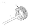
- FIG. 1a is a perspective view of a PET system and FIG. 1b is an enlarged perspective view of a PET detector in the PET system.
- a PET system 100 includes a PET detector 120, a cable 130 one end of which is connected to the PET detector 120, and a PET circuitry 140 connected to the other end of the cable 130.
- a bed 111 for transferring a patient is provided movably on a support 113, and the PET detector 120 is provided in an imaging bore (not shown) with a tubular form configured to allow a patient to be placed therein.
- a plurality of scintillation crystals 121 are arranged in annular shape to form a scintillation crystal array 122.
- the scintillation crystal array 122 is arranged in plural numbers along a length direction of the PET detector 120.
- the other end of the scintillation crystals 121 is connected to a photosensor, thereby configuring the PET detector 120.
- the photosensor (not shown) of the PET detector 120 converts the scintillation from the scintillation crystals 121 into an electrical signal.
- the photosensor may be a photomultiplier tube (PMT), a positive-intrinsic-negative PIN) diode, cadmium telluride (CdTe), cadmium zinc telluride (CZT), an avalanche photodiode (APD), a Geiger-mode avalanche photodiode (GAPD), or the like.
- the PMT was developed in 1974 and is currently the most frequently used photosensor in a PET device. Quantumefficiency is usually 25-30%. Recently, it was improved to 40% or higher. It is characterized by a high signal amplification factor and low noise characteristics and is advantageous in that the operation is very stable. However, high bias voltage requirement and sensitivity to magnetic field make it difficult to be applied in fusion imaging devices such as PET-MR.
- the GAPD is viewed as a promising next-generation photosensor that can replace the PMT, because of high signal amplification factor, low noise characteristics, mass producibility, magnetic resonance (MR) compatibility and operability at low bias voltage.
- the GAPD is a 4-9 mm 2 sized photosensor composed of a plurality of micro-cells having a size of tens to hundreds of micrometers arranged in two dimensions. Each micro-cell consists of an APD operating in Geiger mode. When a photon is incident, an electron is emitted typically with an amplification factor of 10 6 times.
- each micro-cell performs on/off switch operation that detects presence or absence of photon incidence. Assuming that one gamma ray reaches the scintillation crystal and then incident on the GAPD after being converted into multiple photons, the intensity of the incident gamma ray can be calculated by counting the number of the micro-cells with on reactions.
- the linearity problem for the 511 keV gamma ray has to be solved.
- the GAPD consisting of many micro-cells is commonly used in spite of low quantum efficiency.
- the GAPD having a smaller number of cells per unit area and thus having high quantum efficiency can provide high energy data, it is inapplicable to the PET detector because of the linearity problem for the 511 keV gamma ray.
- the present disclosure is directed to providing a positron emission tomography (PET) detector module using a Geiger-mode avalanche photodiode (GAPD) photosensor, which is capable of providing high energy and high energy and reaction depth data while maintaining linearity, a PET detector using the same, and a PET fusion medical imaging device using the same.
- PET positron emission tomography
- GAPD Geiger-mode avalanche photodiode
- the present disclosure provides a PET detector module including: a PET detector unit including a scintillation crystal detecting gamma rays emitted from a living body and converting them into a flash of light and a first GAPD photosensor and a second GAPD photosensor each being connected to either end of the scintillation crystal and converting the light flash into an electrical signal; and a reaction depth determination unit receiving the signals from the PET detector unit and comparing amplitude of the signals detected by the first GAPD photosensor and the second GAPD photosensor, thereby determining the position where the gamma rays are incident on the scintillation crystal (hereinafter, referred to as reaction depth).
- reaction depth receiving the signals from the PET detector unit and comparing amplitude of the signals detected by the first GAPD photosensor and the second GAPD photosensor, thereby determining the position where the gamma rays are incident on the scintillation crystal
- the first GAPD photosensor and the second GAPD photosensor may be a GAPD including micro-cells with a large area of 10 ⁇ m 2 or larger.
- the PET detector module may further include a signal processing unit providing information about energy of the incident gamma rays and reaction time from a combination of a signal output from the reaction depth determination unit and the signals from the PET detector unit.
- the scintillation crystal may be selected from bismuth germanate (BGO), lutetium oxyorthosilicate (LSO), lutetium yttrium oxyorthosilicate (LYSO), lutetium aluminum perovskite (LuAP), lutetium yttrium aluminum perovskite (LuYAP), lanthanum bromide (LaBr 3 ), lutetium iodide (LuI 3 ), gadolinium oxyorthosilicate (GSO), lutetium gadolinium oxyorthosilicate (LGSO) and lutetium aluminum garnet (LuAG).
- BGO bismuth germanate
- LSO lutetium oxyorthosilicate
- LYSO lutetium yttrium oxyorthosilicate
- LuAP lutetium aluminum perovskite
- LuYAP lutetium yttrium aluminum perovskite
- LaBr 3
- the present disclosure provides a PET detector module including: a PET detector unit comprising a scintillation crystal detecting 511 keV gamma rays emitted from a living body through a pair annihilation phenomenon toward opposite directions and converting them into a flash of light and a first GAPD photosensor and a second GAPD photosensor each being connected to either end of the scintillation crystal and converting the light flash into an electrical signal; a signal amplification unit receiving the signals detected by the first GAPD photosensor and the second GAPD photosensor and amplifying the signals; and a reaction depth determination unit receiving the signals from the signal amplification unit and comparing amplitude of the signals detected by the first GAPD photosensor and the second GAPD photosensor, thereby determining the position where the gamma rays are incident on the scintillation crystal (reaction depth).
- a PET detector unit comprising a scintillation crystal detecting 511 keV gamma rays emitted from a living
- the present disclosure provides a PET detector module including a PET detector unit including a scintillation crystal detecting 511 keV gamma rays emitted from a living body through a pair annihilation phenomenon toward opposite directions and converting them into a flash of light and a first GAPD photosensor and a second GAPD photosensor each being connected to either end of the scintillation crystal and converting the light flash into an electrical signal, extended in matrix form, in a polygonal or annular arrangement.
- a PET detector unit including a scintillation crystal detecting 511 keV gamma rays emitted from a living body through a pair annihilation phenomenon toward opposite directions and converting them into a flash of light and a first GAPD photosensor and a second GAPD photosensor each being connected to either end of the scintillation crystal and converting the light flash into an electrical signal, extended in matrix form, in a polygonal or annular arrangement.
- the present disclosure provides a PET detector module including a PET detector unit including a scintillation crystal detecting 511 keV gamma rays emitted from a living body through a pair annihilation phenomenon toward opposite directions and converting them into a flash of light and a first GAPD photosensor and a second GAPD photosensor each being connected to either end of the scintillation crystal and converting the light flash into an electrical signal, connected and arranged in circular shape.
- a PET detector module including a PET detector unit including a scintillation crystal detecting 511 keV gamma rays emitted from a living body through a pair annihilation phenomenon toward opposite directions and converting them into a flash of light and a first GAPD photosensor and a second GAPD photosensor each being connected to either end of the scintillation crystal and converting the light flash into an electrical signal, connected and arranged in circular shape.
- the present disclosure provides a PET-magnetic resonance imaging (MRI) fusion system comprising: an MRI bore allowing a patient to be placed therein and scanning magnetic resonance (MR) images; a PET detector provided in the MRI bore and comprising a scintillation crystal detecting gamma rays emitted from a living body and converting them into a flash of light and a first GAPD photosensor and a second GAPD photosensor each being connected to either end of the scintillation crystal and converting the light flash into an electrical signal, connected and arranged in cylindrical shape; and a circuitry processing signals about the MR images from the MRI bore and the signals from the PET detector and reconstructing images.
- MRI magnetic resonance imaging
- the PET detector module according to the disclosure is capable of providing high energy data and reaction depth data while maintaining linearity.
- the PET detector module exhibits significantly improved linearity and energy resolution. It is applicable to clinical and preclinical PET, especially as a PET detector for scanning small animals, breasts or brain.
- first may be referred to as a second component
- second component may be referred to as a first component.
- the term and/or encompasses both combinations of the plurality of related items disclosed and any one item from among the plurality of related items disclosed.
- FIG. 2 is a graph showing a relationship between the number of micro-cells of a Geiger-mode avalanche photodiode (GAPD) of a positron emission tomography (PET) detector, linearity, quantum efficiency (photon detection efficiency; PDE) and gain.
- GAPD Geiger-mode avalanche photodiode
- PET positron emission tomography
- the smaller the number of the micro-cells of a GAPD photosensor i.e. the larger the size of the micro-cells, amplification factor or quantum efficiency increases, but linearity decreases, making the GAPD photosensor inapplicable as a PET detector.
- the larger the number of the micro-cells of a GAPD photosensor i.e. the smaller the size of the micro-cells, linearity increases, but amplification factor or quantum efficiency decreases.
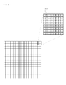
- FIG. 3 shows a GAPD photosensor commonly used in a PET detector
- FIG. 4 shows a GAPD photosensor used in a PET detector according to an embodiment of the present disclosure.
- a commonly used GAPD photosensor comprises 400 micro-cells 310 having an area approximately 10 ⁇ m 2 or smaller per mm 2 .
- a GAPD photosensor according to an embodiment of the present disclosure comprises 100 to 400 micro-cells 410 having an area approximately 10 ⁇ m 2 or larger per mm 2 .
- a GAPD photosensor according to an embodiment of the present disclosure may comprise 100 micro-cells 410 having an area approximately 100 ⁇ m 2 or larger per mm 2 .
- FIG. 5 shows a PET detector module according to an embodiment of the present disclosure.
- a PET detector module 500 comprises a PET detector unit 510, a cable 520, a reaction depth determination unit 530 and a signal processing unit 550.
- a plurality of the PET detector unit 510 are arranged in various forms to constitute a PET detector.
- the PET detector unit 510 comprises a scintillation crystal 511, and a first GAPD photosensor 513 and a second GAPD photosensor 515 each being connected to either end of the scintillation crystal 511.
- the scintillation crystal 511 forms a scintillation crystal array (not shown).
- the scintillation crystal 511 detects 511 keV gamma rays emitted from a living body through a pair annihilation phenomenon toward opposite directions.
- the scintillation crystal may be selected from bismuth germanate (BGO), lutetium oxyorthosilicate (LSO), lutetium yttrium oxyorthosilicate (LYSO), lutetium aluminum perovskite (LuAP), lutetium yttrium aluminum perovskite (LuYAP), lanthanum bromide (LaBr 3 ), lutetium iodide (LuI 3 ), gadolinium oxyorthosilicate (GSO), lutetium gadolinium oxyorthosilicate (LGSO) and lutetium aluminum garnet (LuAG).
- BGO bismuth germanate
- LSO lutetium oxyorthosilicate
- LYSO lutetium yttrium oxyorthosilicate
- LuAP lutetium aluminum perovskite
- LuYAP lutetium yttrium aluminum perovskite
- LaBr 3
- the first GAPD photosensor 513 and the second GAPD photosensor 515 convert the light flash into an electrical signal.
- the cable 520 transmits the electrical signal to the reaction depth determination unit 530.
- the reaction depth determination unit 530 may determine gamma ray reaction depth by comparing the number of the light flashes detected by the first GAPD photosensor 513 and the second GAPD photosensor 515. For example, it may receive the signals from the PET detector unit 510 and compare amplitude of the signals from the first GAPD photosensor 513 and the second GAPD photosensor 515, thereby determining the gamma ray reaction depth.
- the gamma ray reaction depth refers to the position where the gamma rays are incident on the scintillation crystal 511.
- the signal processing unit 550 provides information about energy of the incident gamma rays and reaction time from a combination of a signal output from the reaction depth determination unit 530 and the signals from the PET detector unit 510.
- FIG. 6 shows a PET detector comprising a PET detector module according to an embodiment of the present disclosure.
- a plurality of PET detector units 510 each comprising a scintillation crystal 511 and a first GAPD photosensor 513 and a second GAPD photosensor 515 each being connected to either end of the scintillation crystal 511 are arranged in cylindrical shape to constitute a PET detector.
- the PET detector units 510 may be extended in matrix form, in a polygonal or annular arrangement.
- FIG. 7 shows a PET detector comprising a PET detector module according to another embodiment of the present disclosure.
- a plurality of PET detector units 510 each comprising a scintillation crystal 511 and a first GAPD photosensor 513 and a second GAPD photosensor 515 each being connected to either end of the scintillation crystal 511 are arranged in circular shape to constitute a PET detector.
- the PET detector may be configured in other various shapes using the PET detector units. For example, one or more layer(s) of a plurality of scintillation crystals arranged in matrix form may be provided on the photosensor to constitute the PET detector.
- FIG. 8 shows a PET detector module according to another embodiment of the present disclosure.
- a PET detector module 600 comprises a PET detector 610, a cable 620, a signal amplification unit 630, a reaction depth determination unit 650 and a signal processing unit 670.
- the PET detector 610 comprises a scintillation crystal 611, and a first GAPD photosensor 613 and a second GAPD photosensor 615 each being connected to either end of the scintillation crystal 611.
- signals from the first GAPD photosensor 613 and the second GAPD photosensor 615 which convert a light flash into an electrical signal are transmitted to the signal amplification unit 630 via the cable 620.
- the signal amplification unit 630 amplifies the signals from the first GAPD photosensor 613 and the second GAPD photosensor 615 and transmits them to the reaction depth determination unit 650.
- the reaction depth determination unit 650 may determine gamma ray reaction depth by comparing the number of the light flashes detected by the first GAPD photosensor 613 and the second GAPD photosensor 615.
- the signal processing unit 670 provides information about energy of the incident gamma rays and reaction time from a combination of a signal output from the reaction depth determination unit 650 and the signals from the PET detector unit 610.
- FIG. 9 illustrates an example of determining reaction depth using a PET detector module according to an embodiment of the present disclosure.
- a PET detector unit comprises a scintillation crystal 730 and a first GAPD photosensor 710 and a second GAPD photosensor 720 each being connected to either end of the scintillation crystal730.
- a gamma ray is incident and 10 light flashes are produced, 5 flashes are detected by the first GAPD photosensor 710 and the remaining 5 flashes are detected by the second GAPD photosensor 720.
- the reaction depth determination unit it is determined by the reaction depth determination unit that gamma ray reaction 750 occurred at a position 0.5 in the scintillation crystal 730.
- the gamma ray reaction depth may be determined by comparing amplitude of the signals detected by the first GAPD photosensor 710 and the second GAPD photosensor 720.
- FIG. 10 illustrates an example of determining reaction depth using a PET detector module according to another embodiment of the present disclosure.
- a PET detector unit comprises a scintillation crystal 830 and a first GAPD photosensor 810 and a second GAPD photosensor 820 each being connected to either end of the scintillation crystal830.
- a gamma ray is incident and 10 light flashes are produced, 7 flashes are detected by the first GAPD photosensor 810 and the remaining 3 flashes are detected by the second GAPD photosensor 820. Accordingly, it is determined by the reaction depth determination unit that gamma ray reaction 850 occurred at a position 0.3 in the scintillation crystal 830.
- FIG. 11 shows a PET-magnetic resonance imaging (MRI) fusion system comprising a PET detector using a PET detector module according to an embodiment of the present disclosure and an MRI bore.
- MRI magnetic resonance imaging
- a PET-MRI fusion system 900 comprises an MRI bore 910 allowing a patient to be placed therein and scanning magnetic resonance (MR) images, a PET detector 920 according to an embodiment of the present disclosure provided in the MRI bore 910, a cable 930 one end of which is connected to the PET detector 920, and a circuitry 940 connected to the other end of the cable 930.
- MR magnetic resonance
- a plurality of scintillation crystals 921 are arranged in annular shape to form a scintillation crystal array 922.
- the scintillation crystal array 922 is arranged in plural numbers along a length direction of the PET detector 920.
- a first GAPDphotosensor and a second GAPDphotosensor are connected, thereby configuring the PET detector 920.
- Each of the first GAPD photosensor and the second GAPD photosensor is connected to the circuitry 940 via the cable 930.
- the circuitry 940 processes the signals from the PET detector 920 and signals about the MR images from the MRI bore 910 and reconstructs images.
- the above PET-MRI fusion system 900 is only an example of the PET-MRI fusion system using the PET detector module according to an embodiment of the present disclosure. Those skilled in the art will appreciate that various PET-MRI fusion systems may be configured using the PET detector module according to an embodiment of the present disclosure.
- a PET detector is configured according to an embodiment of the present disclosure using a 3 ⁇ 3 mm 2 sized GAPD consisting of 900 micro-cells and having a photon detection efficiency (PDE) of 50%.
- PDE photon detection efficiency
- N fired_microcell N total_microcells ⁇ 1 - e - ⁇ ⁇ N photons N total_microcells
- N fired_microcell is the number of the fired micro-cells
- N total_microcells is the number of the total micro-cells
- N photons is the number of the incident photons
- ⁇ the photon detection efficiency.
- the photon detection efficiency ⁇ is given as Equation 2.
- ⁇ QE ⁇ F ⁇ ⁇ Geiger where Q.E is the quantum efficiency, F is the fill factor and ⁇ Geiger is the probability of Geiger mode reaction.
- the total number of the fired micro-cells is 868 when a general PET detector is used, whereas it is 1460 when a PET detector according to an embodiment of the present disclosure is used.
- the number of the fired micro-cells is 730 for one GAPD, and the total number of the fired micro-cells is 1460 for two GAPDs.
- FIG. 12 is a graph showing a relationship between the number of incident photons and the number of the fired micro-cells.
- a (dual) PET detector according to an embodiment of the present disclosure was compared with an existing (single) PET detector for the same gamma rays with the same number of photons. More electrons were output when the (dual) PET detector according to an embodiment of the present disclosure was used. Therefore, the (dual) PET detector according to an embodiment of the present disclosure can provide more accurate information about energy and linearity.
- FIG. 13 is a graph showing linearity of a PET detector module according to an embodiment of the present disclosure.
- the linearity is an index indicating whether the number of output electrons (y-axis) is proportional to the energy of incident gamma ray(x-axis).
- an existing photosensor comprising a single GAPD shows a linearity of 86%.
- a PET detector module according to an embodiment of the present disclosure shows an improved linearity of 93%.
- the 511 keV gamma ray can be distinguished well linearly.
- FIG. 14 is a graph showing energy resolution of a PET detector module according to an embodiment of the present disclosure.
- the PET detector module according to an embodiment of the present disclosure shows an energy resolution of 9%. That is, the PET detector module according to an embodiment of the present disclosure exhibits an improved energy resolution.
- module refers to, but is not limited to, a software or hardware component, such as a field-programmable gate array (FPGA) or an application-specific integrated circuit (ASIC), which executes certain tasks.
- a module may be configured to reside in the addressable storage medium, and configured to execute on one or more processors.
- a module may include, by way of example, components, such as software components, object-oriented software components, class components and task components, processes, functions, attributes, procedures, subroutines, segments of program code, drivers, firmware, microcode, circuitry, data, databases, databases structures, tables, arrays and variables.
- the functionality provided for in the components and modules may be combined into fewer components and modules or further separated into additional components and modules.
- the components and modules may be implemented such that they execute one or more CPU(s) in a device or a secure multimedia card.
- the functionalities described above may be implemented by a processor such as a microprocessor, a controller, a microcontroller, an ASIC, etc. according to software or program codes coded to execute such functionalities. Designing, development and implementation of such codes will be easily understood by those skilled in the art based on the description of the present disclosure.
Landscapes
- Health & Medical Sciences (AREA)
- Life Sciences & Earth Sciences (AREA)
- Engineering & Computer Science (AREA)
- Medical Informatics (AREA)
- Physics & Mathematics (AREA)
- Molecular Biology (AREA)
- High Energy & Nuclear Physics (AREA)
- Nuclear Medicine, Radiotherapy & Molecular Imaging (AREA)
- Radiology & Medical Imaging (AREA)
- Animal Behavior & Ethology (AREA)
- Veterinary Medicine (AREA)
- Pathology (AREA)
- Public Health (AREA)
- Biomedical Technology (AREA)
- Heart & Thoracic Surgery (AREA)
- General Health & Medical Sciences (AREA)
- Surgery (AREA)
- Biophysics (AREA)
- Optics & Photonics (AREA)
- General Physics & Mathematics (AREA)
- Spectroscopy & Molecular Physics (AREA)
- Dentistry (AREA)
- Oral & Maxillofacial Surgery (AREA)
- Computer Vision & Pattern Recognition (AREA)
- Nuclear Medicine (AREA)
- Measurement Of Radiation (AREA)
Applications Claiming Priority (1)
| Application Number | Priority Date | Filing Date | Title |
|---|---|---|---|
| KR1020100038418A KR101169708B1 (ko) | 2010-04-26 | 2010-04-26 | 큰 면적을 가진 마이크로셀로 구성된 gapd를 이용한 pet 검출기 모듈 |
Publications (2)
| Publication Number | Publication Date |
|---|---|
| EP2383587A2 true EP2383587A2 (de) | 2011-11-02 |
| EP2383587A3 EP2383587A3 (de) | 2012-08-08 |
Family
ID=44653709
Family Applications (1)
| Application Number | Title | Priority Date | Filing Date |
|---|---|---|---|
| EP10174630A Withdrawn EP2383587A3 (de) | 2010-04-26 | 2010-08-31 | PET-Detektormodul mit GAPD, gebildet aus Mikrozellen mit großen Bereichen |
Country Status (3)
| Country | Link |
|---|---|
| US (1) | US8880144B2 (de) |
| EP (1) | EP2383587A3 (de) |
| KR (1) | KR101169708B1 (de) |
Cited By (2)
| Publication number | Priority date | Publication date | Assignee | Title |
|---|---|---|---|---|
| WO2019041172A1 (en) * | 2017-08-30 | 2019-03-07 | Shenzhen United Imaging Healthcare Co., Ltd. | SYSTEM, METHOD AND DETECTOR MODULE FOR PET IMAGING |
| WO2022052090A1 (zh) * | 2020-09-10 | 2022-03-17 | 深圳先进技术研究院 | Pet探测器单元、pet探测器 |
Families Citing this family (11)
| Publication number | Priority date | Publication date | Assignee | Title |
|---|---|---|---|---|
| WO2010109523A1 (ja) * | 2009-03-25 | 2010-09-30 | 株式会社島津製作所 | 放射線断層撮影装置 |
| US8809794B2 (en) * | 2011-02-02 | 2014-08-19 | Hamamatsu Photonics K.K. | Radiation detector |
| JP2014210047A (ja) * | 2013-04-18 | 2014-11-13 | 株式会社東芝 | X線ct装置 |
| KR101542836B1 (ko) * | 2013-05-27 | 2015-08-10 | 서강대학교산학협력단 | 양전자방출 단층촬영장치용 검출기 및 이를 이용한 양전자방출 단층촬영 시스템 |
| US9606245B1 (en) | 2015-03-24 | 2017-03-28 | The Research Foundation For The State University Of New York | Autonomous gamma, X-ray, and particle detector |
| KR101722314B1 (ko) | 2015-06-08 | 2017-03-31 | 연세대학교 원주산학협력단 | 섬광 픽셀의 교차 배열을 이용한 3차원 감마선 반응 위치 검출 모듈 |
| WO2019000389A1 (en) * | 2017-06-30 | 2019-01-03 | Shanghai United Imaging Healthcare Co., Ltd. | SYSTEM AND METHOD FOR POSITRON EMISSION TOMOGRAPHY |
| WO2019019197A1 (en) | 2017-07-28 | 2019-01-31 | Shenzhen United Imaging Healthcare Co., Ltd. | DETECTION DEVICE FOR POSITRON EMISSION TOMOGRAPHY |
| CN110376633A (zh) * | 2019-07-19 | 2019-10-25 | 东软医疗系统股份有限公司 | 医疗探测器及医疗成像设备 |
| KR102554026B1 (ko) * | 2021-03-11 | 2023-07-11 | 강원대학교산학협력단 | 최대우도함수를 이용한 감마선영상촬영기기 검출기 모듈의 디지털 위치신호 획득 방법 |
| CN116649990B (zh) | 2022-02-21 | 2025-12-12 | 上海联影医疗科技股份有限公司 | 一种探测器系统及成像设备 |
Family Cites Families (7)
| Publication number | Priority date | Publication date | Assignee | Title |
|---|---|---|---|---|
| US7238946B2 (en) * | 2003-06-27 | 2007-07-03 | Siemens Medical Solutions Usa, Inc. | Nuclear imaging system using scintillation bar detectors and method for event position calculation using the same |
| EP1853161A4 (de) * | 2004-12-29 | 2011-03-23 | Siemens Medical Solutions | Kombiniertes pet/mr-system und apd-basierter pet-detektor zur verwendung bei der simultanen pet/mr-darstellung |
| WO2006107727A2 (en) | 2005-04-01 | 2006-10-12 | San Diego State University Foundation | Edge-on sar scintillator devices and systems for enhanced spect, pet, and compton gamma cameras |
| WO2008048694A2 (en) * | 2006-02-01 | 2008-04-24 | Koninklijke Philips Electronics, N.V. | Geiger mode avalanche photodiode |
| WO2007120674A2 (en) * | 2006-04-10 | 2007-10-25 | Quantum Molecular Technologies, Inc. | Imaging apparatus and systems, and related methods |
| CN102608648B (zh) * | 2006-07-28 | 2015-06-03 | 皇家飞利浦电子股份有限公司 | 正电子发射断层摄影中的飞行时间测量 |
| US9588230B2 (en) * | 2008-09-15 | 2017-03-07 | Siemens Medical Solutions Usa, Inc. | Systems and methods for calibrating a silicon photomultiplier-based positron emission tomography system |
-
2010
- 2010-04-26 KR KR1020100038418A patent/KR101169708B1/ko not_active Expired - Fee Related
- 2010-08-31 EP EP10174630A patent/EP2383587A3/de not_active Withdrawn
- 2010-10-14 US US12/904,584 patent/US8880144B2/en not_active Expired - Fee Related
Non-Patent Citations (1)
| Title |
|---|
| PHOTONIQUE SA: "Blue-Green Sensitive Solid State Photomultiplier with 4.4mm2 Active Area", 1 January 2006 (2006-01-01), pages 1 - 3, XP055117257, Retrieved from the Internet <URL:http://www.photonique.ch/DataSheets/SSPM_0606BG4MM.pdf> [retrieved on 20140509] * |
Cited By (4)
| Publication number | Priority date | Publication date | Assignee | Title |
|---|---|---|---|---|
| WO2019041172A1 (en) * | 2017-08-30 | 2019-03-07 | Shenzhen United Imaging Healthcare Co., Ltd. | SYSTEM, METHOD AND DETECTOR MODULE FOR PET IMAGING |
| US11307313B2 (en) | 2017-08-30 | 2022-04-19 | Shanghai United Imaging Healthcare Co., Ltd. | System, method, and detector module for pet imaging |
| US12282124B2 (en) | 2017-08-30 | 2025-04-22 | Shanghai United Imaging Healthcare Co., Ltd. | System, method, and detector module for pet imaging |
| WO2022052090A1 (zh) * | 2020-09-10 | 2022-03-17 | 深圳先进技术研究院 | Pet探测器单元、pet探测器 |
Also Published As
| Publication number | Publication date |
|---|---|
| US20110263965A1 (en) | 2011-10-27 |
| KR20110118983A (ko) | 2011-11-02 |
| US8880144B2 (en) | 2014-11-04 |
| KR101169708B1 (ko) | 2012-07-30 |
| EP2383587A3 (de) | 2012-08-08 |
Similar Documents
| Publication | Publication Date | Title |
|---|---|---|
| US8880144B2 (en) | Pet detector module using GAPD composed of large area micro-cells | |
| Surti et al. | Advances in time-of-flight PET | |
| EP2438468B1 (de) | Pet-detektorsystem mit verbesserten fähigkeiten zur quantifizierung | |
| US9575192B1 (en) | Optical channel reduction method and apparatus for photodetector arrays | |
| Moses | Trends in PET imaging | |
| EP2404196B1 (de) | Temperaturausgleichs- und steuerschaltung für einzelphotonenzähler | |
| EP3508885A1 (de) | Nuklearmedizinisches multi-gammastrahlenphotonen-bildgebungssystem und verfahren mit simultaner arzneimittelemissionszeitkoinzidenz | |
| US9903961B1 (en) | Photodetector array readout multiplexer having summing, pulse shaping, and dynamic-switching circuits | |
| US9529100B2 (en) | Positron emission tomography detector and positron emission tomography system using same | |
| US9869781B2 (en) | Active pulse shaping of solid state photomultiplier signals | |
| Singh | A review of digital PET-CT technology: comparing performance parameters in SiPM integrated digital PET-CT systems | |
| US8115173B2 (en) | Implementation of wavelength shifters in phoswich detectors | |
| Lee et al. | High-resolution time-of-flight PET detector with 100 ps coincidence time resolution using a side-coupled phoswich configuration | |
| US8148697B2 (en) | Implementation of colored wavelength shifters in phoswich detectors | |
| Lee et al. | Advancements in positron emission tomography detectors: from silicon photomultiplier technology to artificial intelligence applications | |
| CN111685785A (zh) | Pet晶体位置查找表的校正方法、装置以及计算机设备 | |
| Zaidi et al. | The new challenges of brain PET imaging technology | |
| US20110270077A1 (en) | Method for removing noise of pet signal using modeling in pet-mri fusion device and pet system in pet-mri fusion device using the same | |
| KR101092648B1 (ko) | Pet 검출기에서의 감마선 펄스 신호의 도달 시간 검출방법 | |
| CN107374661A (zh) | 用于组合检测器信号的系统和方法 | |
| KR101450806B1 (ko) | 양전자방출 단층촬영기기의 센서 이득 제어 방법 및 시스템 | |
| Pizzichemi | Positron Emission Tomography: State of the art and future developments | |
| EP2413163B1 (de) | Verfahren zum Entfernen von Rauschen aus einem PET-Signal mit Filterung in einer PET-MRI-Fusionsvorrichtung und PET-System in der PET-MRi-Fusionsvorrichtung damit | |
| Wang | High spatial resolution dedicated head and neck positron emission tomography system based on cadmium zinc telluride detectors | |
| EP4478091A1 (de) | Systeme und verfahren zur flugzeitpositronenemissionstomographie |
Legal Events
| Date | Code | Title | Description |
|---|---|---|---|
| 17P | Request for examination filed |
Effective date: 20100831 |
|
| AK | Designated contracting states |
Kind code of ref document: A2 Designated state(s): AL AT BE BG CH CY CZ DE DK EE ES FI FR GB GR HR HU IE IS IT LI LT LU LV MC MK MT NL NO PL PT RO SE SI SK SM TR |
|
| AX | Request for extension of the european patent |
Extension state: BA ME RS |
|
| PUAI | Public reference made under article 153(3) epc to a published international application that has entered the european phase |
Free format text: ORIGINAL CODE: 0009012 |
|
| PUAL | Search report despatched |
Free format text: ORIGINAL CODE: 0009013 |
|
| AK | Designated contracting states |
Kind code of ref document: A3 Designated state(s): AL AT BE BG CH CY CZ DE DK EE ES FI FR GB GR HR HU IE IS IT LI LT LU LV MC MK MT NL NO PL PT RO SE SI SK SM TR |
|
| AX | Request for extension of the european patent |
Extension state: BA ME RS |
|
| RIC1 | Information provided on ipc code assigned before grant |
Ipc: G01T 1/29 20060101AFI20120703BHEP |
|
| 17Q | First examination report despatched |
Effective date: 20140516 |
|
| STAA | Information on the status of an ep patent application or granted ep patent |
Free format text: STATUS: THE APPLICATION IS DEEMED TO BE WITHDRAWN |
|
| 18D | Application deemed to be withdrawn |
Effective date: 20141127 |