EP2383544A1 - Optical encoder - Google Patents
Optical encoder Download PDFInfo
- Publication number
- EP2383544A1 EP2383544A1 EP11003455A EP11003455A EP2383544A1 EP 2383544 A1 EP2383544 A1 EP 2383544A1 EP 11003455 A EP11003455 A EP 11003455A EP 11003455 A EP11003455 A EP 11003455A EP 2383544 A1 EP2383544 A1 EP 2383544A1
- Authority
- EP
- European Patent Office
- Prior art keywords
- light receiving
- scale
- areas
- light
- receiving element
- Prior art date
- Legal status (The legal status is an assumption and is not a legal conclusion. Google has not performed a legal analysis and makes no representation as to the accuracy of the status listed.)
- Withdrawn
Links
- 230000003287 optical effect Effects 0.000 title claims abstract description 31
- 230000005856 abnormality Effects 0.000 claims abstract description 65
- 238000003491 array Methods 0.000 abstract description 34
- 238000010586 diagram Methods 0.000 description 7
- 239000002245 particle Substances 0.000 description 7
- 238000005259 measurement Methods 0.000 description 6
- 238000000034 method Methods 0.000 description 3
- 230000000694 effects Effects 0.000 description 2
- 239000000463 material Substances 0.000 description 2
- 238000013461 design Methods 0.000 description 1
- 238000012986 modification Methods 0.000 description 1
- 230000004048 modification Effects 0.000 description 1
- 238000012545 processing Methods 0.000 description 1
Images



Classifications
-
- G—PHYSICS
- G01—MEASURING; TESTING
- G01D—MEASURING NOT SPECIALLY ADAPTED FOR A SPECIFIC VARIABLE; ARRANGEMENTS FOR MEASURING TWO OR MORE VARIABLES NOT COVERED IN A SINGLE OTHER SUBCLASS; TARIFF METERING APPARATUS; MEASURING OR TESTING NOT OTHERWISE PROVIDED FOR
- G01D5/00—Mechanical means for transferring the output of a sensing member; Means for converting the output of a sensing member to another variable where the form or nature of the sensing member does not constrain the means for converting; Transducers not specially adapted for a specific variable
- G01D5/12—Mechanical means for transferring the output of a sensing member; Means for converting the output of a sensing member to another variable where the form or nature of the sensing member does not constrain the means for converting; Transducers not specially adapted for a specific variable using electric or magnetic means
- G01D5/244—Mechanical means for transferring the output of a sensing member; Means for converting the output of a sensing member to another variable where the form or nature of the sensing member does not constrain the means for converting; Transducers not specially adapted for a specific variable using electric or magnetic means influencing characteristics of pulses or pulse trains; generating pulses or pulse trains
- G01D5/24457—Failure detection
- G01D5/24461—Failure detection by redundancy or plausibility
-
- G—PHYSICS
- G01—MEASURING; TESTING
- G01D—MEASURING NOT SPECIALLY ADAPTED FOR A SPECIFIC VARIABLE; ARRANGEMENTS FOR MEASURING TWO OR MORE VARIABLES NOT COVERED IN A SINGLE OTHER SUBCLASS; TARIFF METERING APPARATUS; MEASURING OR TESTING NOT OTHERWISE PROVIDED FOR
- G01D5/00—Mechanical means for transferring the output of a sensing member; Means for converting the output of a sensing member to another variable where the form or nature of the sensing member does not constrain the means for converting; Transducers not specially adapted for a specific variable
- G01D5/12—Mechanical means for transferring the output of a sensing member; Means for converting the output of a sensing member to another variable where the form or nature of the sensing member does not constrain the means for converting; Transducers not specially adapted for a specific variable using electric or magnetic means
- G01D5/244—Mechanical means for transferring the output of a sensing member; Means for converting the output of a sensing member to another variable where the form or nature of the sensing member does not constrain the means for converting; Transducers not specially adapted for a specific variable using electric or magnetic means influencing characteristics of pulses or pulse trains; generating pulses or pulse trains
- G01D5/24471—Error correction
- G01D5/24476—Signal processing
-
- G—PHYSICS
- G01—MEASURING; TESTING
- G01D—MEASURING NOT SPECIALLY ADAPTED FOR A SPECIFIC VARIABLE; ARRANGEMENTS FOR MEASURING TWO OR MORE VARIABLES NOT COVERED IN A SINGLE OTHER SUBCLASS; TARIFF METERING APPARATUS; MEASURING OR TESTING NOT OTHERWISE PROVIDED FOR
- G01D5/00—Mechanical means for transferring the output of a sensing member; Means for converting the output of a sensing member to another variable where the form or nature of the sensing member does not constrain the means for converting; Transducers not specially adapted for a specific variable
- G01D5/26—Mechanical means for transferring the output of a sensing member; Means for converting the output of a sensing member to another variable where the form or nature of the sensing member does not constrain the means for converting; Transducers not specially adapted for a specific variable characterised by optical transfer means, i.e. using infrared, visible, or ultraviolet light
- G01D5/32—Mechanical means for transferring the output of a sensing member; Means for converting the output of a sensing member to another variable where the form or nature of the sensing member does not constrain the means for converting; Transducers not specially adapted for a specific variable characterised by optical transfer means, i.e. using infrared, visible, or ultraviolet light with attenuation or whole or partial obturation of beams of light
- G01D5/34—Mechanical means for transferring the output of a sensing member; Means for converting the output of a sensing member to another variable where the form or nature of the sensing member does not constrain the means for converting; Transducers not specially adapted for a specific variable characterised by optical transfer means, i.e. using infrared, visible, or ultraviolet light with attenuation or whole or partial obturation of beams of light the beams of light being detected by photocells
- G01D5/347—Mechanical means for transferring the output of a sensing member; Means for converting the output of a sensing member to another variable where the form or nature of the sensing member does not constrain the means for converting; Transducers not specially adapted for a specific variable characterised by optical transfer means, i.e. using infrared, visible, or ultraviolet light with attenuation or whole or partial obturation of beams of light the beams of light being detected by photocells using displacement encoding scales
Definitions
- the present invention relates to an optical encoder.
- an optical encoder which includes a scale having a grid-like scale marking formed along a predetermined direction; a light source emitting light to the scale; a light receiving element array including a plurality of light receiving elements arranged along the predetermined direction to output a signal based on light received via the scale; and a measurer measuring a location of the scale, based on the signal output from the light receiving element array (for example, see Japanese Patent Laid-Open Publication No. 2009-198318 ).
- the photoelectric encoder (optical encoder) disclosed in Japanese Patent Laid-Open Publication No. 2009-198318 is configured to be an absolute encoder. On the scale of this photoelectric encoder, an absolute pattern (scale marking) for measuring an absolute location and an incremental pattern (scale marking) for measuring a relative location are formed along a predetermined direction. The absolute pattern and the incremental pattern are patterns that transmit or block light emitted from the light source to generate light and dark sections.
- the photoelectric encoder includes a plurality of photodiode arrays (light receiving element arrays) arranged corresponding to the absolute pattern and the incremental pattern, and a signal processing circuit (measurer) measuring the location of the scale based on a signal output from the photodiode arrays.
- the photoelectric encoder disclosed in Japanese Patent Laid-Open Publication No. 2009-198318 measures an absolute location of the scale by making the absolute pattern a pattern of an M-sequence random number.
- a linear encoder disclosed in Japanese Patent Laid-Open Publication No. 2010-25879 measures an absolute location of a scale by making an upper track (absolute pattern) an equally spaced pattern.
- an optical encoder is explained which measures an absolute location of a scale by making an absolute pattern an equally spaced pattern.
- Fig. 4 is a pattern diagram illustrating an optical encoder 100 in which an absolute pattern is made an equally spaced pattern.
- an axis perpendicular to a plane of the paper is a Y axis
- two axes perpendicular to the Y axis are X and Z axes.
- the optical encoder 100 is configured to be an absolute encoder, and, as Fig.
- FIG. 4 illustrates, includes a scale 110; a light source 120; a lens 130 making light emitted from the light source 120 parallel light; and a circuit board 140 including a plurality of light receiving element arrays 141 - 143 and a measurer 144 measuring a location of the scale 100 based on signals output from the light receiving element arrays 141 - 143.
- the scale 110 includes absolute patterns 111 and 113 formed along the X axis direction for measuring an absolute location of the scale 110, and an incremental pattern 112 formed between the absolute patterns 111 and 113 along the X axis direction for measuring a relative location of the scale 110.
- a light-dark period of the absolute pattern 111 is set to be slightly shorter as compared to a light-dark period of the absolute pattern 113.
- a light-dark period of the incremental pattern 112 is set to be shorter as compared to the light-dark periods of the absolute patterns 111 and 113.
- the light receiving element arrays 141 and 143 output signals based on light emitted from the light source 120 and received via the absolute patterns 111 and 113.
- the light receiving element array 142 outputs a signal based on light emitted from the light source 120 and received via the incremental pattern 112.
- Fig 5 is a pattern diagram illustrating the circuit board 140 of the optical encoder 100.
- the light receiving element arrays 141 - 143 are formed with a plurality of groups each of which includes light receiving elements arranged at equal spacing, and are configured to output by combining signals output from the light receiving elements for each group.
- outputs are combined from a plurality of light receiving elements 141A, which are arranged at every 4 intervals.
- Outputs from light receiving elements 141B - 141D are also combined, similar to the light receiving elements 141A.
- signals output from the groups of light receiving elements 141A - 141D are input to the measurer 144 via amplifiers 145. That is, the light receiving element array 141 is formed with 4 groups each of which includes light receiving elements arranged at equal spacing.
- a period T of the groups in the light receiving element array 141 that is, the period T for which one cycle is from the light receiving element 141A to the light receiving element 141D, is set as the same as the light-dark period of the absolute pattern 111. Therefore, a signal output from the light receiving element array 141 is a 4-phase signal having a 90-degree phase difference.
- Configurations of the light receiving element arrays 142 and 143 are similar to that of the light receiving element array 141.
- a period of the groups in the light receiving element array 142 is set to be the same as the light-dark period of the incremental pattern 112.
- a period of the groups in the light receiving element array 143 is set to be the same as the light-dark period of the absolute pattern 113. That is, the period of the groups in the light receiving element array 142 is set to be shorter as compared to the periods of the groups in the light receiving element arrays 141 and 143.
- the measurer 144 converts the 4-phase signals output from the light receiving element arrays 141 - 143 to 2-phase signals, and, based on the 2-phase signals, generates respective phase signals corresponding to the absolute patterns 111 and 113 and the incremental pattern 112. Based on the phase signals corresponding to the absolute patterns 111 and 113 and the incremental pattern 112, the measurer 144 measures the location of the scale 110, similar to the linear encoder disclosed in Japanese Patent Laid-Open Publication No. 2010-25879 .
- an abnormality may occur in a signal output from the light receiving element arrays 141 - 143 when a shadow S falls on the light receiving element arrays 141 - 143 due to attachment of a foreign particle such as a piece of dirt and the like to the scale 110 or a breakage occurred to the scale 110.
- a foreign particle such as a piece of dirt and the like
- the optical encoder 100 cannot perform an adequate measurement.
- the period of the groups in the light receiving element array 142 is set to be shorter as compared to the periods of the groups in the light receiving element arrays 141 and 143. Therefore, there is a problem that an abnormality occurs easily especially in a signal output from the light receiving element arrays 141 and 143. This is because, as the period of the groups in a light receiving element array becomes shorter, the effect of the shadow S falling on the light receiving element arrays 141 - 143 (due to attachment of a foreign particle such as a piece of dirt and the like to the scale 110 or a breakage occurred to the scale 110) becomes larger.
- a non-limiting feature of the present disclosure is to provide an optical encoder capable of performing an adequate measurement even when an abnormality has occurred in a signal output from a light receiving element array.
- a non-limiting feature of the optical encoder of the present invention includes a scale having a grid-like scale marking formed along a predetermined direction; a light source emitting light to the scale; a light receiving element array including a plurality of light receiving elements arranged along the predetermined direction and outputting a signal based on light received via the scale; and a measurer measuring a location of the scale, based on the signal output from the light receiving element array.
- the light receiving element array is divided into a plurality of areas.
- the measurer includes an abnormality determiner determining whether an abnormality has occurred in each of the areas based a signal output from each of the areas; and a location measurer measuring the location of the scale based on signals output from the areas for each of which it is determined by the abnormality determiner that an abnormality has not occurred.
- the location measurer measures the location of the scale based on signals output from the areas for each of which the abnormality determiner has determined that-an abnormality has not occurred, among the areas of the light receiving element array. Therefore, an adequate measurement can be performed even when an abnormality has occurred in a signal output from the light receiving element array due to attachment of a foreign particle such as a piece of dirt and the like to the scale or a breakage occurred to the scale.
- a shadow falling on the light receiving element array due to attachment of a foreign particle such as a piece of dirt and the like to the scale or a breakage occurred to the scale, moves with respect to the light receiving element array according the location of the scale.
- a gap is formed between the areas of the light receiving element array. Therefore, when a shadow falling on the light receiving element array is smaller than the gap, it can be prevented that the shadow falls straddling between the areas. Therefore, according to the present invention, a more adequate measurement can be performed even when an abnormality has occurred in a signal output from the light receiving element array due to attachment of a foreign particle such as a piece of dirt and the like to the scale or a breakage occurred to the scale.
- the scale marking is a pattern generating equally spaced light and dark sections in the light emitted from the light source; each of the areas is formed with a plurality of groups each of which includes the light receiving elements arranged at equal spacing, and is configured to output by combining signals output from the light receiving elements for each group; a period of the groups is set to be the same as a light-dark period generated by the scale marking; and the abnormality determiner determines whether an abnormality has occurred in each of the areas by comparing signals output from the groups.
- the scale marking is a pattern generating equally spaced light and dark sections in the light emitted from the light source. Therefore, the light received by the light receiving element array via the scale forms light and dark sections in a sinusoidal form along the predetermined direction at an acceptance surface of the light receiving element array.
- the period of the groups in the light receiving element array is set to be the same as the light-dark period generated by the scale marking. Therefore, based on signals output from the groups in the light receiving element array, light and dark sections in a sinusoidal form formed on the acceptance surface of the light receiving element array can be reproduced.
- signals output from the groups in the light receiving element array are signals that combine signals based on light received by the light receiving elements arranged at locations in the same phase as the light and dark sections in a sinusoidal form formed on the acceptance surface of the light receiving element array. Therefore, the abnormality determiner can easily determine whether an abnormality has occurred in each of the areas by comparing signals output from the groups in the light receiving element array.
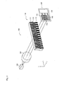
- Fig. 1 illustrates an optical encoder 1 according to the embodiment of the present invention.
- an axis perpendicular to a plane of the paper is a Y axis
- two axes perpendicular to the Y axis are X and Z axes.
- the optical encoder 1 is configured to be an absolute encoder, and, as Fig.
- FIG. 1 illustrates, includes a rectangular plate-shaped scale 2 with a longitudinal direction in the X axis direction; a light source 3 emitting light to the scale 2; a lens 4 converting the light emitted from the light source 3 to parallel light; and a board 5 arranged at a subsequent stage of a light path of the light emitted from the light source 3 passing through the lens 4 and the scale 2.
- the scale 2 is made of a transmissive material and has a grid-like scale marking formed along the X axis direction.
- the scale 2 includes absolute patterns 21 and 23 as scale markings for measuring an absolute location, and an incremental pattern 22 formed between the absolute patterns 21 and 23 as a scale marking for measuring a relative location.
- the absolute patterns 21 and 23 and the incremental pattern 22 are patterns that transmit or block light emitted from the light source 3 to generate equally spaced light and dark sections. Further, a light-dark period of the absolute pattern 21 is set to be slightly shorter as compared to a light-dark period of the absolute pattern 23. And, a light-dark period of the incremental pattern 22 is set to be shorter as compared to the light-dark periods of the absolute patterns 21 and 23.
- Fig. 2 is pattern diagram illustrating the board 5 of the optical encoder 1.
- the board 5 has a plurality of light receiving element arrays 51 - 53, and a measurer 54 measuring a location of the scale 2 based on signals output from the light receiving element arrays 51 - 53.
- the light receiving element array 51 is divided into two areas 511 and 512, and a gap is formed between the areas 511 and 512.
- the light receiving array 53 is divided into two areas 531 and 532, and a gap is formed between the areas 531 and 532.
- the areas 511 and 512, the light receiving element array 52 and the areas 531 and 532 are formed with a plurality of groups each of which includes light receiving elements arranged at equal spacing, and are configured to output by combining signals output from the light receiving elements for each group. Specifically, for example, in the area 511, outputs are combined from two light receiving elements 511A, which are separated by 4 intervals. Outputs from light receiving elements 511B-511D are also combined, similar to the light receiving elements 51 A. Further, signals output from the groups of the light receiving elements 511A-511D are input to the measurer 54 via an amplifier 55 formed from an operational amplifier and the like. That is, the area 511 is formed with 4 groups each of which includes light receiving elements arranged at equal spacing.
- a period T of the groups of the area 511 that is, the period T for which one cycle is from the light receiving element 511A to the light receiving element 511D, is set to be the same as the light-dark period of the absolute pattern 21. Therefore, signals output from the area 511 are 4-phase signals having a 90-degree phase difference.
- Configurations of the light receiving element array 52 and the areas 512, 531 and 532 are similar to that of the area 511.
- a period of the groups in the area 512 is set to be the same as the light-dark period of the absolute pattern 21.
- a period of the groups in the light receiving element array 52 is set as the same as the light-dark period of the incremental pattern 22.
- a period of the groups in each of the areas 531 and 532 is set to be same as the light-dark period of the absolute pattern 23.
- the measurer 54 includes abnormality determiners 541 determining whether an abnormality has occurred in the areas 511, 512, 531 and 532 based on signals output from the areas 511, 512, 531 and 532, and a location measurer 542 measuring a location of the scale 2 based on signals output from the light receiving element arrays 51 - 53.
- the abnormality determiners 541 determine whether an abnormality has occurred in the areas 511, 512, 531 and 532 by comparing signals output from the groups of the areas 511, 512, 531 and 532.
- the absolute patterns 21 and 23 are patterns for generating equally spaced light and dark sections in the light emitted from the light source 3. Therefore, light received by the light receiving element arrays 51 and 53 via the scale 2 form light and dark sections in a sinusoidal form along the predetermined direction at each of acceptance surfaces of the light receiving element arrays 51 and 53.
- signals output from the areas 511, 512, 531 and 532 are 4-phase signals having a 90-degree phase difference.
- the abnormality determiner 541 determines that an abnormality has occurred in the areas 511, 512, 531 or 532.
- a circuit for performing an addition of signals, a comparison with a threshold, and the like can be easily configured using hardware such as an operational amplifier, a comparator, and the like.
- the abnormality determiner 541 When it is determined that an abnormality has not occurred in any of the areas 511 and 512, the abnormality determiner 541 combines signals output from the areas 511 and 512, and outputs.
- the abnormality determiner 541 When it is determined that an abnormality has not occurred in any of the areas 531 and 532, the abnormality determiner 541 combines signals output from the areas 531 and 532, and outputs.
- the location measurer 542 converts 4-phase signals output from the areas 511, 512, 531 and 532 (for which it has been determined by the abnormality determiners 541 that an abnormality has not occurred) and the light receiving element array 52 to 2-phase signals, and, based on the 2-phase signals, generates respective phase signals corresponding to the absolute patterns 21 and 23 and the incremental pattern 22. Based on the phase signals corresponding to the absolute patterns 21 and 23 and the incremental pattern 22, the location measurer 542 measures the location of the scale 2, similar to the linear encoder disclosed in Japanese Patent Laid-Open Publication No. 2010-25879 .
- the location measurer 542 measures the location of the scale 2 based on signals output from the areas 511, 512, 531 and 532 for which the abnormality determiners 541 have determined that an abnormality has not occurred, among the areas 511, 512, 531 and 532 of the light receiving element arrays 51 and 53. Therefore, an adequate measurement can be performed even when an abnormality has occurred in a signal output from the light receiving element arrays 51 and 53 due to attachment of a foreign particle such as a piece of dirt and the like to the scale 2 or a breakage occurred to the scale 2.
- Gaps are formed between the areas 511, 512, 531 and 532 of the light receiving element arrays 51 and 53. Therefore, when a shadow S falling on the light receiving element arrays 51 and 53 is smaller than the gaps, it can be prevented that the shadow S falls straddling between the areas 511, 512, 531 and 532. Therefore, the optical encoder 1 can perform a more adequate measurement even when an abnormality has occurred in a signal output from the light receiving element arrays 51 and 53 due to attachment of a foreign particle such as a piece of dirt and the like to the scale 2 or a breakage occurred to the scale 2.
- the abnormality determiners 541 determine that an abnormality has occurred in the areas 511, 512, 531 or 532. Therefore, whether an abnormality has occurred in the areas 511, 512, 531 and 532 can be easily determined.
- the present invention is not limited to the above described embodiment. Design changes, improvements, and the like, within the scope of achieving the purpose of the present invention, are included in the present invention.
- the light receiving element array 52 was not divided into a plurality of areas. However, it is also possible to divide it into a plurality of areas.
- gaps were formed between the areas 511 and 512 and between the areas 531 and 532. However, it is also possible not to form the gaps.
- the abnormality determiners 541 determine that an abnormality has occurred in the areas 511, 512, 531 and 532. With respect to this point, for example, it is also possible that the abnormality determiners 541 determine whether an abnormality has occurred by adding all 4-phase signals output from the groups in each of the areas. Further, for example, it is also possible that the abnormality determiner 541 determines whether an abnormality has occurred by comparing the 4-phase signals output from the groups in each of the areas to a threshold.
- the abnormality determiner 541 determines whether an abnormality has occurred in each of the areas by comparing the signals output from the groups in each of the areas.
- the 4-phase signals output from the groups of the areas 511, 512, 531 and 532 are used to determine the abnormality of the areas 511, 512, 531 and 532.
- the present invention is not limited to the above embodiment.
- a configuration may be made where a group of 2-3 signals (i.e., 2-phase signals having a 180-degree phase difference or 3-phase signals having a 120-degree phase difference) are output from each of the areas 511, 512, 531 and 532.
- 2-phase signals or 3-phase signals are used to determine the abnormality of the areas 511, 512, 531 and 532.
- the abnormality determiners may determine whether an abnormality has occurred, by checking whether or not the following formula can be established, where 3-phase signals having a 120-degree phase difference are identified as signal 1, signal 2, and signal 3, as shown in Fig. 3 :
- Signal 1 Signal 2 / 2 + Signal 3 / 2
- the above formula can be established. Therefore, it is possible to determine whether an abnormality has occurred by checking whether or not the above formula can be established.
- the period of the groups in the light receiving element arrays 51 ⁇ 53 was set to be the same as the light-dark period of the scale marking in the scale 2.
- the absolute patterns 21 and 23 and the incremental pattern 22 are patterns that transmit or block light emitted from the light source 3 to generate equally spaced light and dark sections.
- the light receiving element arrays 51 - 53 are formed with a plurality of groups each of which includes light receiving elements arranged at equal spacing, and are configured to output by combining signals output from the light receiving elements for each group.
- the abnormality determiner 541 may determine an abnormality according to the configuration of the optical encoder. The point is that the abnormality determiner determines whether an abnormality has occurred in each area based on signals output from the each area of the light receiving element arrays.
- the optical encoder 1 was configured to be an absolute encoder. However, it is also possible to apply the present invention to an incremental encoder. Further, in the above described embodiment, the optical encoder 1 was configured to be a linear encoder. However, it is also possible to apply the present invention to a rotary encoder. In the above described embodiment, the optical encoder 1 is so configured that light transmitting through the scale 2 was received by the light receiving element arrays 51 ⁇ 53. With respect to this point, it is also possible to so configure the optical encoder that light reflected by the scale is received by the light receiving element arrays.
- the present invention can be suitably used as an optical encoder.
Landscapes
- Physics & Mathematics (AREA)
- General Physics & Mathematics (AREA)
- Engineering & Computer Science (AREA)
- Signal Processing (AREA)
- Optical Transform (AREA)
Abstract
An optical encoder includes a scale; a light source; a plurality of light receiving element arrays (three light receiving element arrays) receiving via the scale light emitted from the light source; and a measurer. The first and the third light receiving element arrays are each divided into two areas. The measurer includes an abnormality determiner determining whether an abnormality has occurred in the areas based on signals output from the areas, and a location measurer measuring a location of the scale based on signals output from the areas (for which the abnormality determiner has determined that an abnormality has not occurred) and the second light receiving element array.
Description
- The present invention relates to an optical encoder.
- Conventionally, an optical encoder is known which includes a scale having a grid-like scale marking formed along a predetermined direction; a light source emitting light to the scale; a light receiving element array including a plurality of light receiving elements arranged along the predetermined direction to output a signal based on light received via the scale; and a measurer measuring a location of the scale, based on the signal output from the light receiving element array (for example, see Japanese Patent Laid-Open Publication No.
2009-198318 - The photoelectric encoder (optical encoder) disclosed in Japanese Patent Laid-Open Publication No.
2009-198318 - Here, the photoelectric encoder disclosed in Japanese Patent Laid-Open Publication No.
2009-198318 2010-25879 -
Fig. 4 is a pattern diagram illustrating anoptical encoder 100 in which an absolute pattern is made an equally spaced pattern. InFig. 4 , an axis perpendicular to a plane of the paper is a Y axis, and two axes perpendicular to the Y axis are X and Z axes. Theoptical encoder 100 is configured to be an absolute encoder, and, asFig. 4 illustrates, includes ascale 110; alight source 120; alens 130 making light emitted from thelight source 120 parallel light; and acircuit board 140 including a plurality of light receiving element arrays 141 - 143 and ameasurer 144 measuring a location of thescale 100 based on signals output from the light receiving element arrays 141 - 143. - The
scale 110 includesabsolute patterns scale 110, and anincremental pattern 112 formed between theabsolute patterns scale 110. A light-dark period of theabsolute pattern 111 is set to be slightly shorter as compared to a light-dark period of theabsolute pattern 113. And, a light-dark period of theincremental pattern 112 is set to be shorter as compared to the light-dark periods of theabsolute patterns - The light
receiving element arrays light source 120 and received via theabsolute patterns receiving element array 142 outputs a signal based on light emitted from thelight source 120 and received via theincremental pattern 112. -
Fig 5 is a pattern diagram illustrating thecircuit board 140 of theoptical encoder 100. The light receiving element arrays 141 - 143 are formed with a plurality of groups each of which includes light receiving elements arranged at equal spacing, and are configured to output by combining signals output from the light receiving elements for each group. Specifically, for example, asFig. 5 illustrates, in the lightreceiving element array 141, outputs are combined from a plurality oflight receiving elements 141A, which are arranged at every 4 intervals. Outputs fromlight receiving elements 141B - 141D are also combined, similar to thelight receiving elements 141A. Further, signals output from the groups of light receivingelements 141A - 141D are input to themeasurer 144 viaamplifiers 145. That is, the lightreceiving element array 141 is formed with 4 groups each of which includes light receiving elements arranged at equal spacing. - Here, a period T of the groups in the light receiving
element array 141, that is, the period T for which one cycle is from thelight receiving element 141A to the lightreceiving element 141D, is set as the same as the light-dark period of theabsolute pattern 111. Therefore, a signal output from the lightreceiving element array 141 is a 4-phase signal having a 90-degree phase difference. Configurations of the lightreceiving element arrays receiving element array 141. Here, a period of the groups in the light receivingelement array 142 is set to be the same as the light-dark period of theincremental pattern 112. A period of the groups in the light receivingelement array 143 is set to be the same as the light-dark period of theabsolute pattern 113. That is, the period of the groups in the light receivingelement array 142 is set to be shorter as compared to the periods of the groups in the lightreceiving element arrays - The
measurer 144 converts the 4-phase signals output from the light receiving element arrays 141 - 143 to 2-phase signals, and, based on the 2-phase signals, generates respective phase signals corresponding to theabsolute patterns incremental pattern 112. Based on the phase signals corresponding to theabsolute patterns incremental pattern 112, themeasurer 144 measures the location of thescale 110, similar to the linear encoder disclosed in Japanese Patent Laid-Open Publication No.2010-25879 - However, in such an
optical encoder 100, for example, there is a problem that an abnormality may occur in a signal output from the light receiving element arrays 141 - 143 when a shadow S falls on the light receiving element arrays 141 - 143 due to attachment of a foreign particle such as a piece of dirt and the like to thescale 110 or a breakage occurred to thescale 110. When an abnormality occurs in a signal output from the light receiving element arrays 141 - 143, there is a problem that theoptical encoder 100 cannot perform an adequate measurement. - The period of the groups in the light receiving
element array 142 is set to be shorter as compared to the periods of the groups in the lightreceiving element arrays receiving element arrays scale 110 or a breakage occurred to the scale 110) becomes larger. - A non-limiting feature of the present disclosure is to provide an optical encoder capable of performing an adequate measurement even when an abnormality has occurred in a signal output from a light receiving element array.
- A non-limiting feature of the optical encoder of the present invention includes a scale having a grid-like scale marking formed along a predetermined direction; a light source emitting light to the scale; a light receiving element array including a plurality of light receiving elements arranged along the predetermined direction and outputting a signal based on light received via the scale; and a measurer measuring a location of the scale, based on the signal output from the light receiving element array. The light receiving element array is divided into a plurality of areas. The measurer includes an abnormality determiner determining whether an abnormality has occurred in each of the areas based a signal output from each of the areas; and a location measurer measuring the location of the scale based on signals output from the areas for each of which it is determined by the abnormality determiner that an abnormality has not occurred.
- According to such a configuration, the location measurer measures the location of the scale based on signals output from the areas for each of which the abnormality determiner has determined that-an abnormality has not occurred, among the areas of the light receiving element array. Therefore, an adequate measurement can be performed even when an abnormality has occurred in a signal output from the light receiving element array due to attachment of a foreign particle such as a piece of dirt and the like to the scale or a breakage occurred to the scale.
- In a non-limiting feature of the present invention, it is desirable that a gap is formed between the areas.
- Here, a shadow falling on the light receiving element array, due to attachment of a foreign particle such as a piece of dirt and the like to the scale or a breakage occurred to the scale, moves with respect to the light receiving element array according the location of the scale. In the present invention, a gap is formed between the areas of the light receiving element array. Therefore, when a shadow falling on the light receiving element array is smaller than the gap, it can be prevented that the shadow falls straddling between the areas. Therefore, according to the present invention, a more adequate measurement can be performed even when an abnormality has occurred in a signal output from the light receiving element array due to attachment of a foreign particle such as a piece of dirt and the like to the scale or a breakage occurred to the scale.
- In a non-limiting feature of the present invention, it is desirable that the scale marking is a pattern generating equally spaced light and dark sections in the light emitted from the light source; each of the areas is formed with a plurality of groups each of which includes the light receiving elements arranged at equal spacing, and is configured to output by combining signals output from the light receiving elements for each group; a period of the groups is set to be the same as a light-dark period generated by the scale marking; and the abnormality determiner determines whether an abnormality has occurred in each of the areas by comparing signals output from the groups.
- In a non-limiting feature of the present invention, the scale marking is a pattern generating equally spaced light and dark sections in the light emitted from the light source. Therefore, the light received by the light receiving element array via the scale forms light and dark sections in a sinusoidal form along the predetermined direction at an acceptance surface of the light receiving element array. Here, the period of the groups in the light receiving element array is set to be the same as the light-dark period generated by the scale marking. Therefore, based on signals output from the groups in the light receiving element array, light and dark sections in a sinusoidal form formed on the acceptance surface of the light receiving element array can be reproduced.
- Further, in a non-limiting feature of the present invention, signals output from the groups in the light receiving element array are signals that combine signals based on light received by the light receiving elements arranged at locations in the same phase as the light and dark sections in a sinusoidal form formed on the acceptance surface of the light receiving element array. Therefore, the abnormality determiner can easily determine whether an abnormality has occurred in each of the areas by comparing signals output from the groups in the light receiving element array.
- The present invention is further described in the detailed description which follows, in reference to the noted plurality of drawings by way of non-limiting examples of exemplary embodiments of the present invention, in which like reference numerals represent similar parts throughout the several views of the drawings, and wherein:
-
Fig. 1 illustrates an optical encoder according to an embodiment of the present invention; -
Fig. 2 is a pattern diagram illustrating a board of the optical encoder according to the embodiment of the present invention; -
Fig. 3 is a pattern diagram illustrating a method for abnormality determination using 3-phase signals in an alternative example according to the present invention; -
Fig. 4 is a pattern diagram illustrating an optical encoder in which an absolute pattern is made an equally spaced pattern; and -
Fig. 5 is a pattern diagram illustrating a board of an optical encoder. - The particulars shown herein are by way of example and for purposes of illustrative discussion of the embodiments of the present invention only and are presented in the cause of providing what is believed to be the most useful and readily understood description of the principles and conceptual aspects of the present invention. In this regard, no attempt is made to show structural details of the present invention in more detail than is necessary for the fundamental understanding of the present invention, the description is taken with the drawings making apparent to those skilled in the art how the forms of the present invention may be embodied in practice.
- In the following, an embodiment of the present invention is explained based on the drawings.
Fig. 1 illustrates anoptical encoder 1 according to the embodiment of the present invention. InFig. 1 , an axis perpendicular to a plane of the paper is a Y axis, and two axes perpendicular to the Y axis are X and Z axes. Theoptical encoder 1 is configured to be an absolute encoder, and, asFig. 1 illustrates, includes a rectangular plate-shapedscale 2 with a longitudinal direction in the X axis direction; alight source 3 emitting light to thescale 2; alens 4 converting the light emitted from thelight source 3 to parallel light; and aboard 5 arranged at a subsequent stage of a light path of the light emitted from thelight source 3 passing through thelens 4 and thescale 2. - The
scale 2 is made of a transmissive material and has a grid-like scale marking formed along the X axis direction. Specifically, thescale 2 includesabsolute patterns incremental pattern 22 formed between theabsolute patterns absolute patterns incremental pattern 22 are patterns that transmit or block light emitted from thelight source 3 to generate equally spaced light and dark sections. Further, a light-dark period of theabsolute pattern 21 is set to be slightly shorter as compared to a light-dark period of theabsolute pattern 23. And, a light-dark period of theincremental pattern 22 is set to be shorter as compared to the light-dark periods of theabsolute patterns -
Fig. 2 is pattern diagram illustrating theboard 5 of theoptical encoder 1. AsFig. 2 illustrates, theboard 5 has a plurality of light receiving element arrays 51 - 53, and ameasurer 54 measuring a location of thescale 2 based on signals output from the light receiving element arrays 51 - 53. The lightreceiving element array 51 is divided into twoareas areas element array 51, thelight receiving array 53 is divided into twoareas areas - The
areas element array 52 and theareas area 511, outputs are combined from twolight receiving elements 511A, which are separated by 4 intervals. Outputs from light receivingelements 511B-511D are also combined, similar to thelight receiving elements 51 A. Further, signals output from the groups of thelight receiving elements 511A-511D are input to themeasurer 54 via anamplifier 55 formed from an operational amplifier and the like. That is, thearea 511 is formed with 4 groups each of which includes light receiving elements arranged at equal spacing. - Here, a period T of the groups of the
area 511, that is, the period T for which one cycle is from thelight receiving element 511A to thelight receiving element 511D, is set to be the same as the light-dark period of theabsolute pattern 21. Therefore, signals output from thearea 511 are 4-phase signals having a 90-degree phase difference. Configurations of the lightreceiving element array 52 and theareas area 511. Here, a period of the groups in thearea 512 is set to be the same as the light-dark period of theabsolute pattern 21. A period of the groups in the light receivingelement array 52 is set as the same as the light-dark period of theincremental pattern 22. A period of the groups in each of theareas absolute pattern 23. - The
measurer 54 includesabnormality determiners 541 determining whether an abnormality has occurred in theareas areas location measurer 542 measuring a location of thescale 2 based on signals output from the light receiving element arrays 51 - 53. Theabnormality determiners 541 determine whether an abnormality has occurred in theareas areas - Here, the
absolute patterns light source 3. Therefore, light received by the light receivingelement arrays scale 2 form light and dark sections in a sinusoidal form along the predetermined direction at each of acceptance surfaces of the lightreceiving element arrays areas - Therefore, adding up signals having a 180-degree phase difference, such as signals output from, for example, the
light receiving elements 511A and thelight receiving elements 511C, results in 0. Therefore, in the present embodiment, when adding signals having a 180-degree phase difference (among the 4-phase signals output from the groups of theareas abnormality determiner 541 determines that an abnormality has occurred in theareas - A circuit for performing an addition of signals, a comparison with a threshold, and the like, can be easily configured using hardware such as an operational amplifier, a comparator, and the like. When it is determined that an abnormality has not occurred in any of the
areas abnormality determiner 541 combines signals output from theareas areas abnormality determiner 541 combines signals output from theareas - The
location measurer 542 converts 4-phase signals output from theareas abnormality determiners 541 that an abnormality has not occurred) and the light receivingelement array 52 to 2-phase signals, and, based on the 2-phase signals, generates respective phase signals corresponding to theabsolute patterns incremental pattern 22. Based on the phase signals corresponding to theabsolute patterns incremental pattern 22, thelocation measurer 542 measures the location of thescale 2, similar to the linear encoder disclosed in Japanese Patent Laid-Open Publication No.2010-25879 - The present embodiment as described above provides the following effects. (1) The
location measurer 542 measures the location of thescale 2 based on signals output from theareas abnormality determiners 541 have determined that an abnormality has not occurred, among theareas receiving element arrays element arrays scale 2 or a breakage occurred to thescale 2. - (2) Gaps are formed between the
areas receiving element arrays element arrays areas optical encoder 1 can perform a more adequate measurement even when an abnormality has occurred in a signal output from the light receivingelement arrays scale 2 or a breakage occurred to thescale 2. (3) When adding signals having a 180-degree phase difference (among the 4-phase signals output from the groups of theareas abnormality determiners 541 determine that an abnormality has occurred in theareas areas - The present invention is not limited to the above described embodiment. Design changes, improvements, and the like, within the scope of achieving the purpose of the present invention, are included in the present invention. For example, in the above described embodiment, the light receiving
element array 52 was not divided into a plurality of areas. However, it is also possible to divide it into a plurality of areas. In the above described embodiment, gaps were formed between theareas areas - In the above described embodiment, when adding signals having a 180-degree phase difference (among the 4-phase signals output from the groups of the
areas abnormality determiners 541 determine that an abnormality has occurred in theareas abnormality determiners 541 determine whether an abnormality has occurred by adding all 4-phase signals output from the groups in each of the areas. Further, for example, it is also possible that theabnormality determiner 541 determines whether an abnormality has occurred by comparing the 4-phase signals output from the groups in each of the areas to a threshold. The point is that theabnormality determiner 541 determines whether an abnormality has occurred in each of the areas by comparing the signals output from the groups in each of the areas. In the present embodiment, the 4-phase signals output from the groups of theareas areas areas areas signal 1,signal 2, andsignal 3, as shown inFig. 3 :
- In the above described embodiment, the period of the groups in the light receiving
element arrays 51 ― 53 was set to be the same as the light-dark period of the scale marking in thescale 2. - In the above described embodiment, the
absolute patterns incremental pattern 22 are patterns that transmit or block light emitted from thelight source 3 to generate equally spaced light and dark sections. The light receiving element arrays 51 - 53 are formed with a plurality of groups each of which includes light receiving elements arranged at equal spacing, and are configured to output by combining signals output from the light receiving elements for each group. However, it is also possible to apply an optical encoder of another configuration to the present invention. In this case, theabnormality determiner 541 may determine an abnormality according to the configuration of the optical encoder. The point is that the abnormality determiner determines whether an abnormality has occurred in each area based on signals output from the each area of the light receiving element arrays. - In the above described embodiment, the
optical encoder 1 was configured to be an absolute encoder. However, it is also possible to apply the present invention to an incremental encoder. Further, in the above described embodiment, theoptical encoder 1 was configured to be a linear encoder. However, it is also possible to apply the present invention to a rotary encoder. In the above described embodiment, theoptical encoder 1 is so configured that light transmitting through thescale 2 was received by the light receivingelement arrays 51 ― 53. With respect to this point, it is also possible to so configure the optical encoder that light reflected by the scale is received by the light receiving element arrays. - The present invention can be suitably used as an optical encoder.
- It is noted that the foregoing examples have been provided merely for the purpose of explanation and are in no way to be construed as limiting of the present invention. While the present invention has been described with reference to exemplary embodiments, it is understood that the words which have been used herein are words of description and illustration, rather than words of limitation. Changes may be made, within the purview of the appended claims, as presently stated and as amended, without departing from the scope and spirit of the present invention in its aspects. Although the present invention has been described herein with reference to particular structures, materials and embodiments, the present invention is not intended to be limited to the particulars disclosed herein; rather, the present invention extends to all functionally equivalent structures, methods and uses, such as are within the scope of the appended claims.
- The present invention is not limited to the above described embodiments, and various variations and modifications may be possible without departing from the scope of the present invention.
Claims (3)
- An optical encoder comprising:a scale having a grid scale marking formed along a predetermined direction;a light source configured to emit light to the scale;a light receiving element array comprising a plurality of light receiving elements arranged along the predetermined direction and configured to output a signal based on light received via the scale, the light receiving element array divided into a plurality of areas; anda measurer configured to measure a location of the scale based on the signal output from the light receiving element array, the measurer comprising:an abnormality determiner configured to determine whether an abnormality has occurred in each of the areas based a signal output from each of the areas; anda location measurer configured to measure the location of the scale based on the signal output from each of the areas for each of which it is determined by the abnormality determiner that an abnormality has not occurred.
- The optical encoder according to claim 1, wherein a gap is formed between the areas.
- The optical encoder according claim 1 or 2, wherein:the scale marking is a pattern generating equally spaced light and dark sections in the light emitted from the light source,each of the areas is formed with a plurality of groups, each of which includes the light receiving elements arranged at equal spacing, and is configured to output by combining signals output from the light receiving elements for each group,a period of the groups is set to be the same as a light-dark period generated by the scale marking, andthe abnormality determiner is configured to determine whether an abnormality has occurred in each of the areas by comparing signals output from each of the groups.
Applications Claiming Priority (2)
| Application Number | Priority Date | Filing Date | Title |
|---|---|---|---|
| JP2010104328 | 2010-04-28 | ||
| JP2011089011A JP5887064B2 (en) | 2010-04-28 | 2011-04-13 | Optical encoder |
Publications (1)
| Publication Number | Publication Date |
|---|---|
| EP2383544A1 true EP2383544A1 (en) | 2011-11-02 |
Family
ID=44279949
Family Applications (1)
| Application Number | Title | Priority Date | Filing Date |
|---|---|---|---|
| EP11003455A Withdrawn EP2383544A1 (en) | 2010-04-28 | 2011-04-27 | Optical encoder |
Country Status (4)
| Country | Link |
|---|---|
| US (1) | US20110266424A1 (en) |
| EP (1) | EP2383544A1 (en) |
| JP (1) | JP5887064B2 (en) |
| CN (1) | CN102288202A (en) |
Families Citing this family (14)
| Publication number | Priority date | Publication date | Assignee | Title |
|---|---|---|---|---|
| JP6032924B2 (en) | 2011-04-13 | 2016-11-30 | キヤノン株式会社 | Encoder |
| JP5791340B2 (en) | 2011-04-14 | 2015-10-07 | キヤノン株式会社 | Encoder |
| JP5755010B2 (en) * | 2011-04-14 | 2015-07-29 | キヤノン株式会社 | Encoder |
| JP5755009B2 (en) | 2011-04-14 | 2015-07-29 | キヤノン株式会社 | Encoder |
| JP6408804B2 (en) | 2014-07-03 | 2018-10-17 | キヤノン株式会社 | POSITION DETECTION DEVICE AND LENS DEVICE AND PHOTOGRAPHING DEVICE HAVING THE SAME |
| JP6437802B2 (en) | 2014-11-28 | 2018-12-12 | 株式会社ミツトヨ | Optical encoder |
| JP6517516B2 (en) | 2015-01-21 | 2019-05-22 | 株式会社ミツトヨ | Encoder |
| JP6739911B2 (en) * | 2015-09-04 | 2020-08-12 | キヤノン株式会社 | Position detection device, lens device, and imaging device |
| JP6664211B2 (en) | 2015-12-22 | 2020-03-13 | 株式会社ミツトヨ | Encoder |
| JP6705649B2 (en) | 2015-12-22 | 2020-06-03 | 株式会社ミツトヨ | Encoder |
| JP7066264B2 (en) * | 2018-01-31 | 2022-05-13 | 株式会社ミツトヨ | Encoder and encoder control method |
| JP7096009B2 (en) | 2018-02-21 | 2022-07-05 | 株式会社ミツトヨ | Manufacturing method of position detection encoder and position detection encoder |
| US10502593B1 (en) * | 2018-06-07 | 2019-12-10 | Philip M. Johnson | Linear and rotary multitrack absolute position encoder and methods using the same |
| KR102239911B1 (en) * | 2019-02-21 | 2021-04-13 | 하이윈 마이크로시스템 코포레이션 | Optical encoder and control method thereof |
Citations (5)
| Publication number | Priority date | Publication date | Assignee | Title |
|---|---|---|---|---|
| US6327791B1 (en) * | 1999-06-09 | 2001-12-11 | The Government Of The United States As Represented By The Secretary Of Commerce | Chain code position detector |
| EP1701138A2 (en) * | 2005-03-11 | 2006-09-13 | Mitutoyo Corporation | Photoelectric encoder |
| EP1821075A2 (en) * | 2006-02-15 | 2007-08-22 | Mitutoyo Corporation | Photoelectric encoder |
| JP2009198318A (en) | 2008-02-21 | 2009-09-03 | Mitsutoyo Corp | Photoelectric encoder |
| JP2010025879A (en) | 2008-07-24 | 2010-02-04 | Mitsutoyo Corp | Absolute linear encoder and position adjusting method thereof |
Family Cites Families (10)
| Publication number | Priority date | Publication date | Assignee | Title |
|---|---|---|---|---|
| JPH08304113A (en) * | 1995-05-09 | 1996-11-22 | Yokogawa Electric Corp | Vernier type absolute encoder |
| JP3278361B2 (en) * | 1996-10-25 | 2002-04-30 | オークマ株式会社 | Optical encoder |
| JP4703059B2 (en) * | 2001-08-28 | 2011-06-15 | 株式会社ミツトヨ | Photoelectric encoder |
| JP2005265768A (en) * | 2004-03-22 | 2005-09-29 | Nsk Ltd | Angle detector |
| JP4444715B2 (en) * | 2004-03-31 | 2010-03-31 | 株式会社ミツトヨ | Optical displacement measuring device |
| JP4498024B2 (en) * | 2004-06-15 | 2010-07-07 | キヤノン株式会社 | Optical encoder |
| JP5051973B2 (en) * | 2004-12-20 | 2012-10-17 | オリンパス株式会社 | Reflective optical encoder |
| US20080203283A1 (en) * | 2007-02-23 | 2008-08-28 | Yee Loong Chin | Optical encoder with detector lens |
| JP2009047595A (en) * | 2007-08-21 | 2009-03-05 | Mitsutoyo Corp | Absolute position length-measurement type encoder |
| US8415610B2 (en) * | 2008-06-05 | 2013-04-09 | Mitsubishi Electric Corporation | Optical encoder having a single signal track and an optical detecting part with sine and cosine signals |
-
2011
- 2011-04-13 JP JP2011089011A patent/JP5887064B2/en not_active Expired - Fee Related
- 2011-04-18 US US13/088,601 patent/US20110266424A1/en not_active Abandoned
- 2011-04-27 EP EP11003455A patent/EP2383544A1/en not_active Withdrawn
- 2011-04-28 CN CN2011101092670A patent/CN102288202A/en active Pending
Patent Citations (5)
| Publication number | Priority date | Publication date | Assignee | Title |
|---|---|---|---|---|
| US6327791B1 (en) * | 1999-06-09 | 2001-12-11 | The Government Of The United States As Represented By The Secretary Of Commerce | Chain code position detector |
| EP1701138A2 (en) * | 2005-03-11 | 2006-09-13 | Mitutoyo Corporation | Photoelectric encoder |
| EP1821075A2 (en) * | 2006-02-15 | 2007-08-22 | Mitutoyo Corporation | Photoelectric encoder |
| JP2009198318A (en) | 2008-02-21 | 2009-09-03 | Mitsutoyo Corp | Photoelectric encoder |
| JP2010025879A (en) | 2008-07-24 | 2010-02-04 | Mitsutoyo Corp | Absolute linear encoder and position adjusting method thereof |
Also Published As
| Publication number | Publication date |
|---|---|
| US20110266424A1 (en) | 2011-11-03 |
| JP5887064B2 (en) | 2016-03-16 |
| CN102288202A (en) | 2011-12-21 |
| JP2011247879A (en) | 2011-12-08 |
Similar Documents
| Publication | Publication Date | Title |
|---|---|---|
| US20110266424A1 (en) | Optical encoder | |
| CN105627921B (en) | A kind of the subdivision acquisition system and its measurement method of absolute type encoder | |
| US9759584B2 (en) | Encoder having a detection head with a reference detection receiving grating and a phase compensation receiving grating | |
| US7446306B2 (en) | Photoelectric encoder having multiple light-receiving elements | |
| JP6269334B2 (en) | Multipoint distance measuring device and shape measuring device | |
| JP4358387B2 (en) | Optical position measuring device | |
| EP3026400B1 (en) | Optical encoder | |
| EP1396704A3 (en) | Interferential position measuring device | |
| WO2015011848A1 (en) | Displacement measurement device and displacement measurement method | |
| EP2369304B1 (en) | Photoelectric encoder | |
| CN108204828B (en) | Optical position finder | |
| KR20150097738A (en) | Optical element | |
| CN201740513U (en) | Modularized displacement measuring device with low cost | |
| US10190893B2 (en) | Encoder | |
| CN102589447B (en) | Micro linear displacement sensor based on two-channel grating | |
| CN107017179B (en) | X-Y workbench with position measuring device | |
| CN108151658B (en) | Device and method for judging absolute position of reference point of grating ruler | |
| CN105783738B (en) | A Measuring Method of Incremental Small Range Displacement Sensor | |
| CN109916311B (en) | Scale grating and grating scale displacement sensor | |
| US9689715B2 (en) | Light source array used in an illumination portion of an optical encoder | |
| EP2803948B1 (en) | Reference signal generation apparatus and reference signal generation system | |
| US11353583B2 (en) | Optical position-measurement device with varying focal length along a transverse direction | |
| EP3193138B1 (en) | Method for measuring displacements of object | |
| JP4445498B2 (en) | Transmission type optical encoder | |
| JP6427093B2 (en) | Optical position measuring device |
Legal Events
| Date | Code | Title | Description |
|---|---|---|---|
| AK | Designated contracting states |
Kind code of ref document: A1 Designated state(s): AL AT BE BG CH CY CZ DE DK EE ES FI FR GB GR HR HU IE IS IT LI LT LU LV MC MK MT NL NO PL PT RO RS SE SI SK SM TR |
|
| AX | Request for extension of the european patent |
Extension state: BA ME |
|
| PUAI | Public reference made under article 153(3) epc to a published international application that has entered the european phase |
Free format text: ORIGINAL CODE: 0009012 |
|
| STAA | Information on the status of an ep patent application or granted ep patent |
Free format text: STATUS: THE APPLICATION IS DEEMED TO BE WITHDRAWN |
|
| 18D | Application deemed to be withdrawn |
Effective date: 20120503 |