EP2383193A1 - Corrugated cardboard box with perforated flaps and assembly of cut-outs for obtaining such a box - Google Patents
Corrugated cardboard box with perforated flaps and assembly of cut-outs for obtaining such a box Download PDFInfo
- Publication number
- EP2383193A1 EP2383193A1 EP11006155A EP11006155A EP2383193A1 EP 2383193 A1 EP2383193 A1 EP 2383193A1 EP 11006155 A EP11006155 A EP 11006155A EP 11006155 A EP11006155 A EP 11006155A EP 2383193 A1 EP2383193 A1 EP 2383193A1
- Authority
- EP
- European Patent Office
- Prior art keywords
- box
- flaps
- walls
- flap
- tray
- Prior art date
- Legal status (The legal status is an assumption and is not a legal conclusion. Google has not performed a legal analysis and makes no representation as to the accuracy of the status listed.)
- Granted
Links
Images


Classifications
-
- B—PERFORMING OPERATIONS; TRANSPORTING
- B65—CONVEYING; PACKING; STORING; HANDLING THIN OR FILAMENTARY MATERIAL
- B65D—CONTAINERS FOR STORAGE OR TRANSPORT OF ARTICLES OR MATERIALS, e.g. BAGS, BARRELS, BOTTLES, BOXES, CANS, CARTONS, CRATES, DRUMS, JARS, TANKS, HOPPERS, FORWARDING CONTAINERS; ACCESSORIES, CLOSURES, OR FITTINGS THEREFOR; PACKAGING ELEMENTS; PACKAGES
- B65D5/00—Rigid or semi-rigid containers of polygonal cross-section, e.g. boxes, cartons or trays, formed by folding or erecting one or more blanks made of paper
- B65D5/02—Rigid or semi-rigid containers of polygonal cross-section, e.g. boxes, cartons or trays, formed by folding or erecting one or more blanks made of paper by folding or erecting a single blank to form a tubular body with or without subsequent folding operations, or the addition of separate elements, to close the ends of the body
- B65D5/16—Rigid or semi-rigid containers of polygonal cross-section, e.g. boxes, cartons or trays, formed by folding or erecting one or more blanks made of paper by folding or erecting a single blank to form a tubular body with or without subsequent folding operations, or the addition of separate elements, to close the ends of the body the tubular body being formed with an aperture or removable portion arranged to allow removal or insertion of contents through one or more sides
-
- B—PERFORMING OPERATIONS; TRANSPORTING
- B31—MAKING ARTICLES OF PAPER, CARDBOARD OR MATERIAL WORKED IN A MANNER ANALOGOUS TO PAPER; WORKING PAPER, CARDBOARD OR MATERIAL WORKED IN A MANNER ANALOGOUS TO PAPER
- B31B—MAKING CONTAINERS OF PAPER, CARDBOARD OR MATERIAL WORKED IN A MANNER ANALOGOUS TO PAPER
- B31B50/00—Making rigid or semi-rigid containers, e.g. boxes or cartons
-
- B—PERFORMING OPERATIONS; TRANSPORTING
- B65—CONVEYING; PACKING; STORING; HANDLING THIN OR FILAMENTARY MATERIAL
- B65D—CONTAINERS FOR STORAGE OR TRANSPORT OF ARTICLES OR MATERIALS, e.g. BAGS, BARRELS, BOTTLES, BOXES, CANS, CARTONS, CRATES, DRUMS, JARS, TANKS, HOPPERS, FORWARDING CONTAINERS; ACCESSORIES, CLOSURES, OR FITTINGS THEREFOR; PACKAGING ELEMENTS; PACKAGES
- B65D5/00—Rigid or semi-rigid containers of polygonal cross-section, e.g. boxes, cartons or trays, formed by folding or erecting one or more blanks made of paper
- B65D5/32—Rigid or semi-rigid containers of polygonal cross-section, e.g. boxes, cartons or trays, formed by folding or erecting one or more blanks made of paper having bodies formed by folding and interconnecting two or more blanks each blank forming a body part, whereby each body part comprises at least one outside face of the box, carton or tray
- B65D5/321—Rigid or semi-rigid containers of polygonal cross-section, e.g. boxes, cartons or trays, formed by folding or erecting one or more blanks made of paper having bodies formed by folding and interconnecting two or more blanks each blank forming a body part, whereby each body part comprises at least one outside face of the box, carton or tray at least one container body part formed by folding up portions of a single blank connected to a central panel from all sides
-
- B—PERFORMING OPERATIONS; TRANSPORTING
- B65—CONVEYING; PACKING; STORING; HANDLING THIN OR FILAMENTARY MATERIAL
- B65D—CONTAINERS FOR STORAGE OR TRANSPORT OF ARTICLES OR MATERIALS, e.g. BAGS, BARRELS, BOTTLES, BOXES, CANS, CARTONS, CRATES, DRUMS, JARS, TANKS, HOPPERS, FORWARDING CONTAINERS; ACCESSORIES, CLOSURES, OR FITTINGS THEREFOR; PACKAGING ELEMENTS; PACKAGES
- B65D5/00—Rigid or semi-rigid containers of polygonal cross-section, e.g. boxes, cartons or trays, formed by folding or erecting one or more blanks made of paper
- B65D5/32—Rigid or semi-rigid containers of polygonal cross-section, e.g. boxes, cartons or trays, formed by folding or erecting one or more blanks made of paper having bodies formed by folding and interconnecting two or more blanks each blank forming a body part, whereby each body part comprises at least one outside face of the box, carton or tray
- B65D5/326—Rigid or semi-rigid containers of polygonal cross-section, e.g. boxes, cartons or trays, formed by folding or erecting one or more blanks made of paper having bodies formed by folding and interconnecting two or more blanks each blank forming a body part, whereby each body part comprises at least one outside face of the box, carton or tray at least one container body part formed by folding a single blank to a permanently assembled tube
-
- B—PERFORMING OPERATIONS; TRANSPORTING
- B31—MAKING ARTICLES OF PAPER, CARDBOARD OR MATERIAL WORKED IN A MANNER ANALOGOUS TO PAPER; WORKING PAPER, CARDBOARD OR MATERIAL WORKED IN A MANNER ANALOGOUS TO PAPER
- B31B—MAKING CONTAINERS OF PAPER, CARDBOARD OR MATERIAL WORKED IN A MANNER ANALOGOUS TO PAPER
- B31B2105/00—Rigid or semi-rigid containers made by assembling separate sheets, blanks or webs
- B31B2105/002—Making boxes characterised by the shape of the blanks from which they are formed
-
- B—PERFORMING OPERATIONS; TRANSPORTING
- B31—MAKING ARTICLES OF PAPER, CARDBOARD OR MATERIAL WORKED IN A MANNER ANALOGOUS TO PAPER; WORKING PAPER, CARDBOARD OR MATERIAL WORKED IN A MANNER ANALOGOUS TO PAPER
- B31B—MAKING CONTAINERS OF PAPER, CARDBOARD OR MATERIAL WORKED IN A MANNER ANALOGOUS TO PAPER
- B31B2110/00—Shape of rigid or semi-rigid containers
- B31B2110/30—Shape of rigid or semi-rigid containers having a polygonal cross section
-
- B—PERFORMING OPERATIONS; TRANSPORTING
- B65—CONVEYING; PACKING; STORING; HANDLING THIN OR FILAMENTARY MATERIAL
- B65D—CONTAINERS FOR STORAGE OR TRANSPORT OF ARTICLES OR MATERIALS, e.g. BAGS, BARRELS, BOTTLES, BOXES, CANS, CARTONS, CRATES, DRUMS, JARS, TANKS, HOPPERS, FORWARDING CONTAINERS; ACCESSORIES, CLOSURES, OR FITTINGS THEREFOR; PACKAGING ELEMENTS; PACKAGES
- B65D2519/00—Pallets or like platforms, with or without side walls, for supporting loads to be lifted or lowered
- B65D2519/00004—Details relating to pallets
- B65D2519/00258—Overall construction
- B65D2519/00313—Overall construction of the base surface
- B65D2519/00328—Overall construction of the base surface shape of the contact surface of the base
- B65D2519/00333—Overall construction of the base surface shape of the contact surface of the base contact surface having a stringer-like shape
-
- B—PERFORMING OPERATIONS; TRANSPORTING
- B65—CONVEYING; PACKING; STORING; HANDLING THIN OR FILAMENTARY MATERIAL
- B65D—CONTAINERS FOR STORAGE OR TRANSPORT OF ARTICLES OR MATERIALS, e.g. BAGS, BARRELS, BOTTLES, BOXES, CANS, CARTONS, CRATES, DRUMS, JARS, TANKS, HOPPERS, FORWARDING CONTAINERS; ACCESSORIES, CLOSURES, OR FITTINGS THEREFOR; PACKAGING ELEMENTS; PACKAGES
- B65D2519/00—Pallets or like platforms, with or without side walls, for supporting loads to be lifted or lowered
- B65D2519/00004—Details relating to pallets
- B65D2519/00547—Connections
- B65D2519/00706—Connections structures connecting the lid or cover to the side walls or corner posts
- B65D2519/00711—Connections structures connecting the lid or cover to the side walls or corner posts removable lid or covers
-
- B—PERFORMING OPERATIONS; TRANSPORTING
- B65—CONVEYING; PACKING; STORING; HANDLING THIN OR FILAMENTARY MATERIAL
- B65D—CONTAINERS FOR STORAGE OR TRANSPORT OF ARTICLES OR MATERIALS, e.g. BAGS, BARRELS, BOTTLES, BOXES, CANS, CARTONS, CRATES, DRUMS, JARS, TANKS, HOPPERS, FORWARDING CONTAINERS; ACCESSORIES, CLOSURES, OR FITTINGS THEREFOR; PACKAGING ELEMENTS; PACKAGES
- B65D5/00—Rigid or semi-rigid containers of polygonal cross-section, e.g. boxes, cartons or trays, formed by folding or erecting one or more blanks made of paper
- B65D5/02—Rigid or semi-rigid containers of polygonal cross-section, e.g. boxes, cartons or trays, formed by folding or erecting one or more blanks made of paper by folding or erecting a single blank to form a tubular body with or without subsequent folding operations, or the addition of separate elements, to close the ends of the body
- B65D5/12—Rigid or semi-rigid containers of polygonal cross-section, e.g. boxes, cartons or trays, formed by folding or erecting one or more blanks made of paper by folding or erecting a single blank to form a tubular body with or without subsequent folding operations, or the addition of separate elements, to close the ends of the body with end closures formed separately from tubular body
-
- B—PERFORMING OPERATIONS; TRANSPORTING
- B65—CONVEYING; PACKING; STORING; HANDLING THIN OR FILAMENTARY MATERIAL
- B65D—CONTAINERS FOR STORAGE OR TRANSPORT OF ARTICLES OR MATERIALS, e.g. BAGS, BARRELS, BOTTLES, BOXES, CANS, CARTONS, CRATES, DRUMS, JARS, TANKS, HOPPERS, FORWARDING CONTAINERS; ACCESSORIES, CLOSURES, OR FITTINGS THEREFOR; PACKAGING ELEMENTS; PACKAGES
- B65D5/00—Rigid or semi-rigid containers of polygonal cross-section, e.g. boxes, cartons or trays, formed by folding or erecting one or more blanks made of paper
- B65D5/42—Details of containers or of foldable or erectable container blanks
- B65D5/4204—Inspection openings or windows
-
- B—PERFORMING OPERATIONS; TRANSPORTING
- B65—CONVEYING; PACKING; STORING; HANDLING THIN OR FILAMENTARY MATERIAL
- B65D—CONTAINERS FOR STORAGE OR TRANSPORT OF ARTICLES OR MATERIALS, e.g. BAGS, BARRELS, BOTTLES, BOXES, CANS, CARTONS, CRATES, DRUMS, JARS, TANKS, HOPPERS, FORWARDING CONTAINERS; ACCESSORIES, CLOSURES, OR FITTINGS THEREFOR; PACKAGING ELEMENTS; PACKAGES
- B65D5/00—Rigid or semi-rigid containers of polygonal cross-section, e.g. boxes, cartons or trays, formed by folding or erecting one or more blanks made of paper
- B65D5/42—Details of containers or of foldable or erectable container blanks
- B65D5/64—Lids
- B65D5/68—Telescope flanged lids
Definitions
- the present invention relates to a box of generally parallelepipedal shape of corrugated cardboard sheet, for the packaging and transport of objects, said box comprising a cover formed of a lateral belt comprising a front wall, a rear wall, side walls and a top, and a tray forming a bottom comprising a central panel having four main sides each respectively provided with a first flap.
- the invention also relates to a set of blanks for the constitution of such a box.
- the present invention finds a particularly important application although not exclusive in the field of boxes used to present goods directly on pallet in large areas and so as to avoid handling costs and additional intermediate storage.
- this type of packaging allows easy and enjoyable access to products for the consumer regardless of the location of the box, at least on both front and rear accessible sides of the pallet.
- the present invention aims to avoid these disadvantages.
- a box of parallelepipedal general shape in corrugated cardboard sheet for the packaging and transport of objects, said box comprising a cover formed of a lateral belt comprising a front wall, a rear wall, walls side and a top, and a tray forming a bottom comprising a central panel having four main sides each respectively provided with a first flap, characterized in that the front and rear walls are U-shaped and each define with the top a central recess adapted to allow manual entry by a user into the box of an object laterally and / or from above, in that two first flaps facing said tray comprise a tab at each of their lateral ends, respectively fixed on the first adjacent flap to form said tray, and in that at least one of the front, rear or side walls of the lid is only attached to a corresponding first side flap of the tray, by one or more partially pre-cut portions and / or one or more bonding points allowing separation between lid walls and first flaps of the tray by manual separation obtained by exerting a force perpendic
- Such a box allows the use of cardboard of different qualities between the sidewall belt and the bottom.
- the bottom may be made of cardboard less resistant than the walls that must hold the compression, the bottom only to hold, buckling.
- the consumer can therefore use all levels of the pallet, either in trays or through openwork faces.
- the products are therefore instantly and directly available on the pallet itself, the only operation to be carried out to install the assembly being to remove the plastic film used during transport around the packaging, then possibly and as and when, remove the lids by simple lateral separation of lid / tray separation.
- the packaging according to the invention is perfectly stackable, and this by allowing a good resistance to compression.
- the lid of the box is easily disconnectable, which allows the display function to be on the pallet itself; either on a linear shelf.
- the invention also proposes a set of blanks for the constitution of a box for packaging and transporting objects, comprising at least two corrugated cardboard blanks, namely a first cutout suitable for forming the lid of the box, comprising a sequence of at least four main components, namely a front flap, a rear flap and two lateral flaps, terminated by a fastening tab and interconnected by first folding lines parallel to each other, said series of flaps forming the outer walls of the box and being connected on one side to a series of flaps by second fold lines perpendicular to said first fold lines, said flap sequence being adapted to at least partially form the top of the box and comprising two opposite second sidewalk flaps, each connected to the upper periphery of a corresponding lateral flap, and a second cutout forming the bottom of said box-shaped box, comprising a central panel provided with first flaps on its sides, characterized in that the front and rear flaps are in U shape and each define with the top a central recess adapted to allow manual entry by
- the front and rear panels comprise a central stiffening bar, for example tear-off, located in the middle or substantially in the middle of the corresponding obvious.
- said portions partially precut are at least two in number respectively located on either side of the side walls of the box.
- the first flaps of the second cutout are arranged to be fixed on said first blank by winding around a volume of determined dimensions during the formation of the box, before definitive joining.
- the first cut has eight flaps, namely four main flaps separated from each other by intermediate flaps adapted to form cut corners of the box.
- the invention also proposes a method for producing a polygonal box packaging box from at least two blanks of cardboard sheet or corrugated cardboard material, namely a first blank comprising a series of at least four main parts terminated by a fastening tab, interconnected by first folding lines parallel to each other, said sequence of flaps forming the outer walls of the box and being connected on one side to a series of flaps by second lines bending perpendicular to said first fold lines, said flap suite forming the top of said box, and a second cutout having at least two panels interconnected by a third fold line, i.e.
- said second blank forming the bottom tray-shaped bottom for said box, characterized in that the box is formed by winding the blanks around a determined volume, two reinforcing sheets are placed on a mandrel which is then introduced into the packaging to be made to then be left reinforcement inside said box by removing said mandrel.
- the box 1 comprises a lateral belt 2 of flaps, namely a front flap 3, U-shaped, a rear flap 4 also U-shaped and two side flaps 5 and 6 equal, rectangular interconnected by fold lines parallel 7.
- the bottom forming the tray is integral with the lower part of the lateral belt forming a lid on either side by a partially pre-cut portion P open, and / or by bonding points C in broken lines on the Figures 4 and 5 .
- This pre-cut part which is only glued on the adjacent wall, is easily disconnected from the cover.
- the box comprises a top 11 having two second flaps 12 and 13 opposing constituting sidewalks open to the fold line each provided on their peripheral lateral edges of an overhang or protrusion 14, 15, which will allow to exert the necessary counterpressure to adhering said second flaps on the outer face of third flaps.
- the top of the box 1 also comprises two third flaps 16, 17 substantially T-shaped whose base is connected by a fold line 18 to the corresponding lateral face 5, 6 and which comprises recesses 19 on its lateral ends away from the fold line, of rounded shape, on the one hand to allow the folding of the second flaps during the formation of the box, and on the other hand to allow the perforated portion 20 of the second U-shaped flaps overturned remain open, the third flaps 16, 17 are also glued on the underside of the first flaps.
- the third flaps 16, 17 are of width less than half the width of the side flaps.
- the top of the box is meanwhile perforated on a part so that it is thus constituted two recesses 21, in one piece with the openwork portions 22 of the U of the front flaps 3 and rear 4, allowing manual entry easy by a user, directly in the box, whose structure still allows the rigid maintenance of the whole.
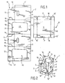
- the figure 2 shows the assembly 2, 8 of cutouts for making the box 1 of the figure 1 .
- the same reference numbers have been used to simplify the description of the same elements or similar elements in the rest of the description.
- the lateral belt 2 is terminated by a rectangular gluing tab 7 'connected to an adjacent lateral flap 7 by a fold line parallel to those connecting the other flaps of the suite.
- the figure 3 shows a variant 23 of lateral belt flaps relative to that of the figure 2 , with recesses 24 located on the fold line 18, forms complementary to the lugs 14, 15, adapted to cooperate with said lugs snap.
- Horizontal strips of stiffening cardboard 25 are here provided in the U-shaped recesses, for example two-thirds or three-quarters of the height of the flap, delimiting an upper recess portion 26 straddling the junction line between flaps. front or rear and second flaps 12 and 13 and a lower portion 27 of course.
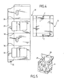
- FIGS. 4 and 5 show another embodiment of an assembly 28 according to the invention, whose second flaps 29, of generally identical shape to the second flaps 12, 13, are extended on each side on their lateral edges, tongues 30, foldable towards the adjacent side face 5, 6.
- these tongues are intended to be glued back on the outer side of the side flap, allowing the blocking of the sidewalks that will here allow the stacking of crates and their holding on pallets after partial emptying of objects even better.
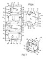
- FIGS 6 and 7 are front and perspective views of an eight-sided box 31.
- the figure 6 shows, flat, a first cut 32 of sheet material for the manufacture of an embodiment of the invention with eight sides and a second cut 33 for forming the bottom tray of the box shown in FIG. figure 7 .
- the cutout 32 comprises a series of eight aligned rectangular flaps 34, 35, 36, 37, 38, 40, 41, two by two connected by preformed and parallel fold lines 42.
- a tab 43 connected to the end flaps by a folding line parallel to the fold lines 42 mentioned above.
- first flaps 44, 45, 46, 47 are provided.
- Each first flap is articulated to the corresponding main flap by a preformed fold line 48.
- fold lines are aligned or substantially aligned and perpendicular to the fold lines 42.
- the rectangular flaps all have the same height or substantially the same height.
- the flaps 37 and 41 intended to form the side walls of the box of rectangular shape, identical, and provided with a handle 49 and the flaps 35 and 39 intended to form the front and rear walls provided with a perforated portion 50 straddling the corresponding fold line 48 between said wall and the adjacent flaps 44 and 46, themselves perforated towards said fold line and intended to partly form the top of the box, and secondly the flaps 34, 36, 38 and 40 suitable for forming the cut corners of the lid.
- This blank is intended to form by winding, and after fastening the shutters, the box of the figure 7 .
- the second cutout 33 is itself formed of an octagonal bottom 51 provided on each of its main sides 52 corresponding to the side faces and front and rear of third rectangular flaps 53 and 54 opposite two by two, namely two small flaps 53 devoid of lateral tabs, and two larger flaps 54 terminated on either side by first tabs 55, themselves connected to second tabs 56 to match, when the lower tray is formed around the lower portion 57 of the second cut (folded over itself to form the lid of the box 31), the cut corners of said tray, the last end tabs 56 being stuck on the adjacent small flaps 53, rectangular, corresponding to the other two sides facing the second cutting.
- the first flaps are of generally rectangular shape similar to the flaps 12, 13 and 16, 17 of the figures 2 and 3 , but moreover they comprise parts 58 biased outwards at their lateral end, on both sides, on at least part, and from the fold lines 48 of connection with the flaps.
- horizontal tongues or reinforcement bars 59 which are tear-off at the corresponding recesses 50, are also provided in the main lateral faces.
- lateral lugs 60 are provided for snapping into corresponding recesses 61 on the fold lines connecting with the flaps.
- connection between the tray and the bottom of the lid through two points of adhesive 62 on at least one of the faces and preferably on two side faces of the package and / or a portion pre-cut 63, for example in a closed manner on the flaps 53.
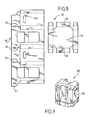
- FIGS. 8 and 9 show another embodiment of a set of cutouts 64 and a box 65 according to the invention on eight sides.
- first flaps is similar to that of the first flaps 29 with reference to the Figures 4 and 5 , taking into account of course intermediate flaps forming cut corners as described this time with reference to the figure 6 .
- Lateral tongues 67 are therefore provided and glued (cf. figure 9 ) on the side walls 68 to stiffen the whole.
- a central panel 75 rectangular or substantially rectangular, forming the upper face of the cover, connected laterally by fold lines 76 to two side panels 77, 78 forming at least partly the front and rear walls of the box, symmetrical with respect to the central panel, U-shaped bar which is towards the base of the box, and each respectively provided with a large substantially rectangular course 79, substantially occupying 2/3 or 4/5 or 5/6 è è of the surface of the panel, partly astride the fold lines 76, allowing access to the product once the body formed in accordance with the figure 11 .
- the side panels 77, 78 and the central panel 75 are provided on either side with fourth flaps adapted to form at least partially the side walls, said fourth flaps being substantially rectangular or trapezoidal.
- the cut 73 comprises two sets of lateral flaps 80, 81, 82 rectangular or substantially rectangular of the same height, namely a central flap 81 with a hollow handle 84 and two symmetrical flaps 80 and 82 with respect to the flap 81, each provided with a notch 85, covering the handle.
- the second cut is identical to or similar to the cutting of the figure 2 .
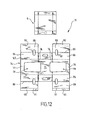
- the figure 12 shows as to another embodiment of a blank with three panels, namely a central panel 75 similar to the central panel described with reference to the figure 10 and two side panels 77 and 78 also identical to the side panels described with reference to FIG. figure 10 , but this time provided on each side with side flaps in three parts, namely a first flap 86 connected directly by a single fold line 87 to the side panels 77, 78 corresponding, a second flap 88 connected to the first flap by a double fold line 89 and a third flap. 90 forming tab connected to the second flap via a last fold line 91 parallel to the first two.
- the box is of the type described with reference to the figure 1 and obtained by simultaneously coating the first and second blanks around a first mandrel (not shown).
- step A a mandrel 93 of octagonal section with cut corners is brought (step A), on which are plated (step B) on either side two panels 94, having a central face 95 and two cut corners 96, on the faces 97 of the octagonal mandrel.
- step C The latter, with the veneered panels, is then lowered (step C) inside 98 of the parallelepiped body 1 until the bottom stop (step D).
- step E the mandrel is restricted in width in a manner known in itself and emerged upwards (step E) so as to obtain in step F the box 92 with reinforcements 94 inside.
- the figure 14 is in turn a perspective view of a pallet 98 of cases 99 according to the embodiment of the figure 1 equipped with 100 products regularly installed.
- the formation, filling and closing can be easily mechanized, while allowing the use of light and recycled papers by favoring a rigid structure since as already specified, because of the two-part packaging, it is possible to use two types of cardboard, one to resist compression, the other to resist buckling of the bottom.
- the present invention is not limited to the embodiments more particularly described. On the contrary, it embraces all the variants and in particular those in which the set of cuts comprises three cuts, to form respectively the bottom, the top of the lid and the side walls of said lid.
Abstract
Description
La présente invention concerne une boîte de forme générale parallélépipédique en feuille de carton ondulé, pour le conditionnement et le transport d'objets, ladite boîte comportant un couvercle formé d'une ceinture latérale comprenant une paroi avant, une paroi arrière, des parois latérales et un dessus, et une barquette formant un fond comprenant un panneau central comportant quatre cotés principaux chacun respectivement muni d'un premier rabat.The present invention relates to a box of generally parallelepipedal shape of corrugated cardboard sheet, for the packaging and transport of objects, said box comprising a cover formed of a lateral belt comprising a front wall, a rear wall, side walls and a top, and a tray forming a bottom comprising a central panel having four main sides each respectively provided with a first flap.
L'invention concerne également un ensemble de découpes pour la constitution d'une telle boîte.The invention also relates to a set of blanks for the constitution of such a box.
La présente invention trouve une application particulièrement importante bien que non exclusive dans le domaine des boîtes utilisées pour présenter des marchandises directement sur palette dans les grandes surfaces et ce de façon à éviter des coûts de manutentions et de stockage intermédiaire supplémentaire.The present invention finds a particularly important application although not exclusive in the field of boxes used to present goods directly on pallet in large areas and so as to avoid handling costs and additional intermediate storage.
En particulier, ce type d'emballage autorise un accès facile et agréable aux produits pour le consommateur quel que soit l'emplacement de la boîte, au moins sur les deux faces avant et arrière accessibles de la palette.In particular, this type of packaging allows easy and enjoyable access to products for the consumer regardless of the location of the box, at least on both front and rear accessible sides of the pallet.
On connaît déjà des dispositifs permettant d'avoir un accès en direct à des produits à l'intérieur d'emballages disposés sur une palette.Devices are already known for having direct access to products inside packages arranged on a pallet.
De tels dispositifs ne sont pas satisfaisants. En effet, ils nécessitent en général l'arrachage d'une partie des parois pour rendre les produits accessibles. De plus, lorsqu'il s'agit de barquettes ajourées, ces dernières n'ont pas une solidité importante, ce qui ne permet pas d'avoir des stockages sur palettes de produits lourds et/ou sur un nombre d'étages important.Such devices are not satisfactory. Indeed, they generally require the tearing of part of the walls to make the products accessible. In addition, when it comes to perforated trays, the latter do not have a significant strength, which does not allow storage on pallets of heavy products and / or a large number of floors.
La présente invention vise à éviter ces inconvénients.The present invention aims to avoid these disadvantages.
Dans ce but elle propose essentiellement une boîte de forme générale parallélépipédique en feuille de carton ondulé, pour le conditionnement et le transport d'objets, ladite boîte comportant un couvercle formé d'une ceinture latérale comprenant une paroi avant, une paroi arrière, des parois latérales et un dessus, et une barquette formant un fond comprenant un panneau central comportant quatre cotés principaux chacun respectivement muni d'un premier rabat, caractérisé en ce que
les parois avant et arrière sont en forme de U et définissent chacune avec le dessus un évidemment central propre à permettre la saisie manuelle par un utilisateur dans la boîte d'un objet latéralement et/ou par le dessus,
en ce que deux premiers rabats en vis à vis de ladite barquette comportent une languette à chacune de leurs extrémités latérales, respectivement fixée sur le premier rabat adjacent pour former ladite barquette,
et en ce qu'au moins une des parois avant, arrière ou latérales du couvercle est uniquement fixée à un premier rabat latéral correspondant de la barquette, par une ou plusieurs portions partiellement prédécoupées et/ou un ou plusieurs points de collage autorisant une désolidarisation entre parois du couvercle et premiers rabats de la barquette par écartement manuel obtenu en exerçant une force perpendiculairement aux parois.For this purpose it essentially proposes a box of parallelepipedal general shape in corrugated cardboard sheet, for the packaging and transport of objects, said box comprising a cover formed of a lateral belt comprising a front wall, a rear wall, walls side and a top, and a tray forming a bottom comprising a central panel having four main sides each respectively provided with a first flap, characterized in that
the front and rear walls are U-shaped and each define with the top a central recess adapted to allow manual entry by a user into the box of an object laterally and / or from above,
in that two first flaps facing said tray comprise a tab at each of their lateral ends, respectively fixed on the first adjacent flap to form said tray,
and in that at least one of the front, rear or side walls of the lid is only attached to a corresponding first side flap of the tray, by one or more partially pre-cut portions and / or one or more bonding points allowing separation between lid walls and first flaps of the tray by manual separation obtained by exerting a force perpendicular to the walls.
Une telle boîte autorise l'utilisation de carton de qualités différentes entre la ceinture de parois latérales et le fond. Par exemple, le fond peut être en carton moins résistant que les parois qui doivent tenir à la compression, le fond devant uniquement tenir,au flambage.Such a box allows the use of cardboard of different qualities between the sidewall belt and the bottom. For example, the bottom may be made of cardboard less resistant than the walls that must hold the compression, the bottom only to hold, buckling.
Avec l'invention il va être possible d'avoir un accès aux marchandises sur les deux faces principales de la boîte, pour prendre les produits devant et derrière la palette. De plus, elle permet une utilisation combinée avec ou sans la fonction présentoir sur une barquette dégagée de son couvercle.With the invention it will be possible to have access to goods on the two main faces of the box, to take the products in front of and behind the pallet. In addition, it allows a combined use with or without the display function on a tray disengaged from its lid.
Le consommateur peut dès lors se servir à tous les niveaux de la palette, soit dans les barquettes, soit au travers des faces ajourées.The consumer can therefore use all levels of the pallet, either in trays or through openwork faces.
Avec l'invention, les produits sont donc instantanément et directement disponibles sur la palette elle-même, la seule opération à effectuer pour installer l'ensemble étant d'ôter le film plastique utilisé pendant le transport autour de l'emballage, puis éventuellement et au fur et à mesure, d'ôter les couvercles par-simple écartement latéral de désolidarisation couvercle/barquette.With the invention, the products are therefore instantly and directly available on the pallet itself, the only operation to be carried out to install the assembly being to remove the plastic film used during transport around the packaging, then possibly and as and when, remove the lids by simple lateral separation of lid / tray separation.
L'emballage selon l'invention est parfaitement gerbable, et ce en autorisant une bonne tenue à la compression. Le couvercle de la boîte est facilement déconnectable, ce qui autorise la fonction présentoir soit sur la, palette elle-même; soit sur une étagère linéaire.The packaging according to the invention is perfectly stackable, and this by allowing a good resistance to compression. The lid of the box is easily disconnectable, which allows the display function to be on the pallet itself; either on a linear shelf.
Dans des modes de réalisation avantageux, on a de plus recours à l'une et/ou à l'autre des dispositions suivantes :
- les parois avant et arrière comportent une barre de rigidification horizontale située au milieu ou sensiblement au milieu de l'évidemment correspondant, avantageusement arrachable ;
- lesdites portions partiellement prédécoupées ou points de collage sont au moins au nombre de deux respectivement situés de part et d'autre sur les parois latérales de la boite ;
- les parois avant, arrière et latérales, sont séparées entre elles par des parois intermédiaires pour former une boîte à huit cotés, à coins coupés ;
- le couvercle est imbriqué dans la barquette ;
- la où les portions partiellement prédécoupées appartiennent à la barquette ;
- la ou les portions partiellement prédécoupées sont prédécoupées selon une ligne ouverte ;
- la ou les portions partiellement prédécoupées sont découpées selon une ligne fermée ;
- le couvercle comporte au moins quatre panneaux formant les parois, respectivement reliés entre eux par des lignes de pliage parallèles et une languette de collage d'extrémité, et en ce que le dessus de la boîte comprend deux deuxièmes rabats opposés à bord longitudinal libre en trottoir, ajourés en forme de U, dont l'extrémité des branches est reliée à l'extrémité des branches du U des parois avant et arrière correspondantes ;
- les deuxièmes rabats ajourés comportent sur leur coté latéral des débords de contre pression ;
- les deuxièmes rabats comportent sur leur coté latéral des deuxièmes languettes collées sur la paroi latérale en vis à vis ;
- le dessus de la boîte comporte de plus des troisièmes rabats reliés à la périphérie supérieure des parois latérales, collés sur les deuxièmes rabats pour former ledit dessus ;
- le couvercle comporte trois panneaux, à savoir un panneau central rectangulaire formant la face supérieure du couvercle de la caisse reliée latéralement par des lignes de pliage à deux panneaux latéraux formant au moins en partie les parois avant et arrière de la boîte, lesdits panneaux latéraux et/ou ledit panneau central étant munis de part et d'autre de quatrièmes rabats propres à former au moins partiellement lesdites parois latérales ;
- chaque paroi latérale comporte une poignée ;
- la boîte comporte de plus deux panneaux individuels latéraux de renfort interne, propres à coopérer à contact avec la face interne des parois latérales et à renforcer la tenue verticale de ladite boîte.
- the front and rear walls comprise a horizontal stiffening bar located in the middle or substantially in the middle of the corresponding recess, preferably tear-off;
- said portions partially precut or bonding points are at least two in number respectively located on either side of the side walls of the box;
- the front, rear and side walls are separated from each other by intermediate walls to form an eight-sided box with cut corners;
- the lid is nested in the tray;
- where the partially precut portions belong to the tray;
- the partially pre-cut portion or portions are precut along an open line;
- the partially precut portion or portions are cut along a closed line;
- the cover comprises at least four panels forming the walls, respectively interconnected by parallel folding lines and an end gluing tab, and in that the top of the box comprises two opposite second flaps with a free longitudinal sidewalk edge , U-shaped perforations, the end of the branches is connected to the end of the branches of the U of the corresponding front and rear walls;
- the second perforated flaps have on their lateral side counter pressure overhangs;
- the second flaps have on their lateral side second tongues glued to the side wall opposite;
- the top of the box further comprises third flaps connected to the upper periphery of the side walls, glued on the second flaps to form said top;
- the cover comprises three panels, namely a rectangular central panel forming the upper face of the cover of the box laterally connected by fold lines with two side panels forming at least partly the front and rear walls of the box, said side panels and / or said central panel being provided on either side with fourth flaps adapted to form at least partially said side walls;
- each side wall has a handle;
- the box further comprises two individual internal reinforcement lateral panels adapted to cooperate in contact with the internal face of the side walls and to reinforce the vertical holding of said box.
L'invention propose également un ensemble de découpes pour la constitution d'une boîte pour le conditionnement et le transport d'objets, comprenant au moins deux découpes en carton ondulé, à savoir une première découpe propre à former le couvercle de la boîte, comportant une suite d'au moins quatre volets principaux, à savoir un volet avant, un volet arrière et deux volets latéraux, terminée par une languette de fixation et reliés entre eux par des premières lignes de pliage parallèles entre elles, ladite suite de volets formant les parois externes de la boîte et étant reliée d'un coté à une suite de rabats par des deuxièmes lignes de pliage perpendiculaires auxdites premières lignes de pliage, ladite suite de rabats étant propre à former au moins partiellement le dessus de la boîte et comprenant deux deuxièmes rabats opposés en trottoir, chacun relié à la périphérie supérieure d'un volet latéral correspondant, et une deuxième découpe formant le fond de ladite boîte en forme de barquette, comportant un panneau central muni de premiers rabats sur ses cotés, caractérisé en ce que les Volets avant et arrière sont en forme de U et définissent chacun avec le dessus un évidemment central propre à permettre la saisie manuelle par un utilisateur dans la boîte d'un objet latéralement et/ou par le dessus, en ce que deux premiers rabats en vis à vis de ladite deuxième découpe comportent une languette à chacune de leurs extrémités latérales, respectivement destinée à être fixée sur le premier rabat adjacent pour former ladite barquette, et en ce qu'au moins une des parois avant, arrière ou latérales du couvercle est agencées pour être uniquement fixée à un premier rabat latéral correspondant de la barquette, par une ou plusieurs portions partiellement prédécoupées et/ou un ou plusieurs points de collage autorisant une désolidarisation entre parois du couvercle et premiers rabats de la barquette par écartement manuel obtenu en exerçant une force perpendiculairement aux parois.The invention also proposes a set of blanks for the constitution of a box for packaging and transporting objects, comprising at least two corrugated cardboard blanks, namely a first cutout suitable for forming the lid of the box, comprising a sequence of at least four main components, namely a front flap, a rear flap and two lateral flaps, terminated by a fastening tab and interconnected by first folding lines parallel to each other, said series of flaps forming the outer walls of the box and being connected on one side to a series of flaps by second fold lines perpendicular to said first fold lines, said flap sequence being adapted to at least partially form the top of the box and comprising two opposite second sidewalk flaps, each connected to the upper periphery of a corresponding lateral flap, and a second cutout forming the bottom of said box-shaped box, comprising a central panel provided with first flaps on its sides, characterized in that the front and rear flaps are in U shape and each define with the top a central recess adapted to allow manual entry by a user into the box of an object laterally and / or from above, in that two first flaps facing said second cutout comprise a tongue at each of their lateral ends, respectively intended to be fixed on the first adjacent flap for forming er said tray, and in that at least one of the front, rear or side walls of the lid is arranged to be attached solely to a corresponding first side flap of the tray, by one or more partially pre-cut portions and / or one or more bonding points allowing separation between the lid walls and first flaps of the tray by manual separation obtained by exerting a force perpendicular to the walls.
Dans un mode de réalisation avantageux, les panneaux avant et arrière comportent une barre de rigidification centrale, par exemple arrachable, située au milieu ou sensiblement au milieu de l'évidemment correspondant.In an advantageous embodiment, the front and rear panels comprise a central stiffening bar, for example tear-off, located in the middle or substantially in the middle of the corresponding obvious.
Avantageusement, lesdites portions partiellement prédécoupées sont au moins au nombre de deux respectivement situées de part et d'autre sur les parois latérales de la boîte.Advantageously, said portions partially precut are at least two in number respectively located on either side of the side walls of the box.
Dans un mode - de réalisation avantageux les premiers rabats de la deuxième découpe sont agencés pour être fixés sur ladite première découpe par enroulement autour d'un volume de dimensions déterminées lors de la formation de la boîte, avant solidarisation définitive.In an advantageous embodiment, the first flaps of the second cutout are arranged to be fixed on said first blank by winding around a volume of determined dimensions during the formation of the box, before definitive joining.
Avantageusement, la première découpe présente huit volets, à savoir quatre volets principaux séparés entre eux par des volets intermédiaires propres à former des coins coupés de la boîte.Advantageously, the first cut has eight flaps, namely four main flaps separated from each other by intermediate flaps adapted to form cut corners of the box.
L'invention propose également un procédé pour la réalisation d'une boîte d'emballage à section polygonale à partir d'au moins deux découpes de matière en feuille de carton ou carton ondulé, à savoir une première découpe comportant une suite d'au moins quatre volets principaux terminée par une languette de fixation, reliés entre eux par des premières lignes de pliage parallèles entre elles, ladite suite de volets formant les parois externes de la boîte et étant reliée d'un coté à une suite de rabats par des deuxièmes lignes de pliage perpendiculaires auxdites premières lignes de pliage, ladite suite de rabats formant le dessus de ladite boîte, et une deuxième découpe comportant au moins deux panneaux reliés entre eux par une troisième ligne de.pliage, à savoir un premier panneau et un ou plusieurs seconds panneaux, ladite deuxième découpe formant le fond en forme de barquette inférieure pour ladite boîte, caractérisée en ce que
on forme la boîte par enroulement des découpes autour d'un volume déterminé, on plaque deux feuilles de renfort sur un mandrin qu'on introduit ensuite dans l'emballage à fabriquer pour les laisser ensuite en renfort à l'intérieur de ladite boîte en retirant ledit mandrin.The invention also proposes a method for producing a polygonal box packaging box from at least two blanks of cardboard sheet or corrugated cardboard material, namely a first blank comprising a series of at least four main parts terminated by a fastening tab, interconnected by first folding lines parallel to each other, said sequence of flaps forming the outer walls of the box and being connected on one side to a series of flaps by second lines bending perpendicular to said first fold lines, said flap suite forming the top of said box, and a second cutout having at least two panels interconnected by a third fold line, i.e. a first panel and one or more seconds panels, said second blank forming the bottom tray-shaped bottom for said box, characterized in that
the box is formed by winding the blanks around a determined volume, two reinforcing sheets are placed on a mandrel which is then introduced into the packaging to be made to then be left reinforcement inside said box by removing said mandrel.
L'invention sera mieux comprise à la lecture de la description qui suit de modes de réalisation donnés ci-après à titre d'exemples non limitatifs.The invention will be better understood on reading the following description of embodiments given below by way of non-limiting examples.
La description se réfère aux dessins qui l'accompagnent dans lesquels :
- La
figure 1 est une vue en perspective de face d'un premier mode de réalisation d'une boîte selon l'invention. - La
figure 2 est une vue de dessus d'un ensemble de découpes permettant d'obtenir la boîte de lafigure 1 . - La
figure 3 est un autre mode de réalisation en vue de dessus d'un ensemble de découpes selon l'invention. - La
figure 4 est un troisième mode de réalisation d' un ensemble de découpes selon l'invention. - La
figure 5 est une vue en perspective de la boîte obtenue avec l'ensemble de lafigure 4 . - La
figure 6 est une vue de dessus en plan d'un quatrième mode de réalisation d'un ensemble selon l'invention à huit côtés. - La
figure 7 est une vue en perspective d'une boîte obtenue l'ensemble de lafigure 6 . - Les
figures 8 sont respectivement des vues en plan d'un ensemble de découpes, et en perspective de la boîte formée correspondant à un cinquième mode de réalisation selon l'invention.et 9 - Les
figures 10 et 11 sont d'une part une vue de dessus en plan d'un ensemble et d'autre part une vue en perspective de la boîte formée, correspondant à un sixième mode de réalisation. - La
figure 12 montre en plan un septième mode de réalisation d'un ensemble de découpes selon l'invention. - La
figure 13 montre les étapes de formation d'une boîte avec renfort en utilisant un mandrin selon un mode de réalisation de l'invention. - La
figure 14 est une vue en perspective d'une palette de boîtes selon le mode de réalisation de l'invention plus particulièrement décrit ici. - La
figure 1 montre une boîte 1 parallélépipédique par exemple en feuille de carton ondulé double face de 3 mm d'épaisseur pour le conditionnement d'objets (non représentés) par exemple constitués par des objets lourds type bouteilles de produits ménagers ou boîtes de conserve.
- The
figure 1 is a front perspective view of a first embodiment of a box according to the invention. - The
figure 2 is a top view of a set of cutouts to obtain the box of thefigure 1 . - The
figure 3 is another embodiment in top view of a set of blanks according to the invention. - The
figure 4 is a third embodiment of a set of blanks according to the invention. - The
figure 5 is a perspective view of the box obtained with the whole of thefigure 4 . - The
figure 6 is a top plan view of a fourth embodiment of an assembly according to the invention with eight sides. - The
figure 7 is a perspective view of a box got the whole of thefigure 6 . - The
Figures 8 and 9 are respectively plan views of a set of cuts, and in perspective of the formed box corresponding to a fifth embodiment according to the invention. - The
Figures 10 and 11 are on the one hand a plan view of a set and on the other hand a perspective view of the formed box, corresponding to a sixth embodiment. - The
figure 12 shows in plan a seventh embodiment of a set of blanks according to the invention. - The
figure 13 shows the steps of forming a box with reinforcement using a mandrel according to one embodiment of the invention. - The
figure 14 is a perspective view of a pallet of boxes according to the embodiment of the invention more particularly described here. - The
figure 1 shows aparallelepiped box 1, for example, a 3 mm thick double-faced corrugated cardboard sheet for the packaging of objects (not shown), for example constituted by heavy objects such as bottles of household products or cans.
La boîte 1 comprend une ceinture latérale 2 de volets, à savoir un volet avant 3, en forme de U, un volet arrière 4 également en forme de U et deux volets latéraux 5 et 6 égaux, rectangulaires reliés entre eux par des lignes de pliage parallèles 7.The
Elle comprend de plus un fond 8 formé d'un panneau central 9 muni sur chacun de ses côtés de premiers rabats 10 rectangulaires ou sensiblement rectangulaires, dont deux rabats opposés munis de languette 10' collés sur la périphérie externe des rabats adjacents pour former une barquette rigide.It further comprises a bottom 8 formed of a
Le fond formant barquette est solidaire avec la partie inférieure de la ceinture latérale formant couvercle de part et d'autre par une portion partiellement prédécoupée P ouverte, et/ou par des point de collage C en trait interrompus sur les
Cette partie prédécoupée, qui est seule collée sur la paroi adjacente, est donc facilement désolidarisable du couvercle.This pre-cut part, which is only glued on the adjacent wall, is easily disconnected from the cover.
La boîte comprend un dessus 11 comportant deux deuxièmes rabats 12 et 13 opposés constituant des trottoirs ajourés vers la ligne de pliage munis chacun sur leurs bords latéraux périphériques d'un débord ou excroissance 14, 15, qui va permettre d'exercer la contrepression nécessaire pour coller lesdits deuxièmes rabats sur la face externe de troisième rabats.The box comprises a top 11 having two
Le dessus de la boîte 1 comprend en effet également deux troisièmes rabats 16, 17 sensiblement en forme de T dont la base est reliée par une ligne de pliage 18 à la face latérale correspondante 5, 6 et qui comprend des évidements 19 sur ses extrémités latérales à distance de la ligne de pliage, de forme arrondie, d'une part pour autoriser le repliage des deuxièmes rabats lors de la formation de la boîte, et d'autre part permettre à la partie ajourée 20 des deuxièmes rabats en forme de U renversé de rester dégagée, les troisièmes rabats 16, 17 étant par ailleurs collés sur la face inférieure des premiers rabats.The top of the
Les troisièmes rabats 16, 17 sont de largeur inférieure à la moitié de la largeur des volets latéraux.The third flaps 16, 17 are of width less than half the width of the side flaps.
Le dessus de la boîte est quant-à-lui ajouré sur une partie de sorte qu'il est ainsi constitué deux évidements 21, d'une pièce avec les parties ajourées 22 du U des volets avant 3 et arrière 4, autorisant la saisie manuelle aisée par un utilisateur, directement dans la boîte, dont la structure autorise néanmoins le maintien rigide de l'ensemble.The top of the box is meanwhile perforated on a part so that it is thus constituted two
La
La
Des barrettes horizontales en carton 25, de rigidification sont ici prévues dans les évidements en U, par exemple au deux tiers ou au trois quarts de la hauteur du volet, délimitant une partie supérieure 26 d'évidement à cheval sur la ligne de jonction entre volets avant ou arrière et deuxièmes rabats 12 et 13 et une partie inférieure 27 d'évidemment.Horizontal strips of stiffening
Le collage des troisièmes rabats 16, 17 sur les deuxièmes rabats 12, 13 permet de rigidifier l'ensemble et d'éviter la torsion des faces latérales.The gluing of the
Les
Plus précisément ces languettes sont prévues pour être collées en retour sur la face externe du volet latéral, permettant le blocage des trottoirs qui vont ici autoriser le gerbage des caisses et leur tenue sur palettes après vidage partiel des objets de façon encore améliorée.More specifically these tongues are intended to be glued back on the outer side of the side flap, allowing the blocking of the sidewalks that will here allow the stacking of crates and their holding on pallets after partial emptying of objects even better.
Les
La
Plus précisément la découpe 32 comporte une suite de huit volets rectangulaires alignés 34, 35, 36, 37, 38, 40, 41, deux à deux reliés par des lignes de pliage préformées et parallèles 42.More precisely, the
Le long du bord libre du volet extrême 41 de la suite de volets est disposée une languette 43 reliée aux volets extrêmes par une ligne de pliage parallèle aux lignes de pliage 42 ci-dessus mentionnées.Along the free edge of the end flap 41 of the flap suite is disposed a
Par ailleurs d'un côté de la suite de volets sont prévus des premiers rabats 44, 45, 46, 47.Furthermore on one side of the flap suite are provided
Chaque premier rabat est articulé au volet principal correspondant par une ligne de pliage préformée 48.Each first flap is articulated to the corresponding main flap by a preformed
Ces lignes de pliage sont alignées ou sensiblement alignées et perpendiculaires aux lignes de pliage 42.These fold lines are aligned or substantially aligned and perpendicular to the fold lines 42.
Les volets rectangulaires présentent tous la même hauteur ou sensiblement de la même hauteur.The rectangular flaps all have the same height or substantially the same height.
Ils comportent d'une part les volets 37 et 41 destinés à former les parois latérales de la boîte de forme rectangulaire, identiques, et munis d'une poignée 49 et les volets 35 et 39 destinés à former les parois avant et arrière munis d'une partie ajourée 50 à cheval sur la ligne de pliage 48 correspondante entre ladite paroi et les rabats adjacents 44 et 46, eux-mêmes ajourés vers ladite ligne de pliage et destinés à former en partie le dessus de la boîte, et d'autre part les volets 34, 36, 38 et 40 intermédiaires propres à former les coins coupés du couvercle.They comprise on the one hand the
Ce flan est destiné à former par enroulement, et après solidarisation des volets, la boîte de la
La deuxième découpe 33 est quant-à-elle formée d'un fond 51 octogonal muni sur chacun de ses côtés principaux 52 correspondant aux faces latérales et avant et arrière de troisièmes rabats rectangulaires 53 et 54 opposés deux à deux, à savoir deux petits rabats 53 dénués de languettes latérales, et deux plus grands rabats 54 terminés de part et d'autre par des premières languettes 55, elles-mêmes reliées à des deuxièmes languettes 56 pour épouser, lorsque la barquette inférieure est formée autour de la partie inférieure 57 de la deuxième découpe (repliée sur elle-même pour former le couvercle de la boîte 31), les coins coupés de ladite barquette, les dernières languettes d'extrémité 56 étant collées sur les petits rabats adjacents 53, rectangulaires, correspondant aux deux autres côtés en vis à vis de la deuxième découpe.The
Les premiers rabats sont de forme généralement rectangulaire similaires aux rabats 12, 13 et 16, 17 des
Dans le mode de réalisation de la
De même, comme pour les découpes de la
Selon l'invention il est également prévu une solidarisation entre la barquette et la partie inférieure du couvercle par le biais de deux points de colle 62 sur au moins une des faces et avantageusement sur deux des faces latérales de l'emballage et/ou une portion prédécoupée 63 par exemple de façon fermée sur les rabats 53.According to the invention there is also provided a connection between the tray and the bottom of the lid through two points of adhesive 62 on at least one of the faces and preferably on two side faces of the package and / or a
Les
Ici le mode de réalisation des premiers rabats est similaire à celui des premiers rabats 29 en référence aux
Des languettes latérales 67 sont donc prévues et collées (cf.
On a représenté sur les
Plus précisément il est prévu un panneau central 75 rectangulaire ou sensiblement rectangulaire, formant la face supérieure du couvercle, relié latéralement par des lignes de pliage 76 à deux panneaux latéraux 77, 78 formant au moins en partie les parois avant et arrière de la boîte, symétriques par rapport au panneau central, en forme de U dont la barre est vers la base de la boîte, et chacun respectivement muni d'un grand évidemment 79 sensiblement rectangulaire, occupant sensiblement les 2/3 ou 4/5è ou 5/6è de la surface du panneau, à cheval en partie sur les lignes de pliage 76, permettant l'accès au produit une fois la caisse formée conformément à la
Les panneaux latéraux 77, 78 et le panneau central 75 sont munis de part et d'autre de quatrièmes rabats propres à former au moins partiellement les parois latérales, lesdits quatrièmes rabats étant sensiblement rectangulaires ou trapézoïdaux.The
Plus précisément en référence à la
La deuxième découpe est quant à elle identique ou similaire à la découpe de la
La
On a représenté sur la
La boîte est du type de celle décrite en référence à la
On amène tout d'abord (étape A) un mandrin 93 de section octogonale à coins coupés, sur lequel sont plaqués (étape B) de part et d'autre deux panneaux 94, comportant une face centrale 95 et deux coins coupés 96 latéraux, sur les faces 97 du mandrin octogonal.Firstly, a
Ce dernier, avec les panneaux plaqués, est alors descendu (étape C) à l'intérieur 98 de la caisse parallélépipédique 1 jusqu'en butée basse (étape D).The latter, with the veneered panels, is then lowered (step C) inside 98 of the
Puis le mandrin est restreint en largeur de façon connue en elle-même et ressorti vers le haut (étape E) de façon à obtenir à l'étape F la boîte 92 avec renforts 94 à l'intérieur.Then the mandrel is restricted in width in a manner known in itself and emerged upwards (step E) so as to obtain in step F the
La
Comme on le constate, il est possible d'extraire les produits 100 en partie basse 101, tout en conservant des boîtes pleines en partie haute 102.As can be seen, it is possible to extract the
Par exemple, certains objets ont été extraits des caisses 99', 99", 99''', sans déstabiliser pour autant la palette qui reste solide et de présentation agréable pour les consommateurs.For example, certain objects have been extracted from the
Ainsi, il est possible avec l'invention de constituer une palette complète, d'objets ou de produits, de les livrer directement en magasin et de présenter les objets ou produits en l'état au consommateur, sans aucune manipulation sur les emballages, c'est-à-dire sans arrachage de face, sans utilisation de cutter ni d'ouverture de rabat.Thus, it is possible with the invention to constitute a complete pallet, of objects or products, to deliver them directly in a store and to present the objects or products in the state to the consumer, without any manipulation on the packaging. that is to say without front pulling, without the use of a cutter or flap opening.
La formation, le remplissage et la fermeture peuvent être aisément mécanisés, tout en autorisant l'utilisation de papiers légers et recyclés en privilégiant une structure rigide puisque comme déjà précisé, du fait de l'emballage en deux parties, il est possible d'utiliser deux types de carton, un pour résister à la compression, l'autre pour résister au flambage du fond.The formation, filling and closing can be easily mechanized, while allowing the use of light and recycled papers by favoring a rigid structure since as already specified, because of the two-part packaging, it is possible to use two types of cardboard, one to resist compression, the other to resist buckling of the bottom.
Comme il va de soi et comme il résulte également de ce qui précède, la présente invention n'est pas limitée aux modes de réalisation plus particulièrement décrits. Elle en embrasse au contraire toutes les variantes et notamment celles où l'ensemble de découpes comporte trois découpes, pour former respectivement le fond, le dessus du couvercle et les parois latérales dudit couvercle.As is obvious and as also follows from the above, the present invention is not limited to the embodiments more particularly described. On the contrary, it embraces all the variants and in particular those in which the set of cuts comprises three cuts, to form respectively the bottom, the top of the lid and the side walls of said lid.
Claims (20)
les parois avant et arrière (3, 4 ; P, 35, 37 ; 78) sont en forme de U et définissent chacune avec le dessus un évidemment central (22, 50, 79) propre à permettre la saisie manuelle par un utilisateur dans la boîte d'un objet latéralement et/ou par le dessus, en ce que deux premiers rabats (10, 54) en vis à vis de ladite barquette comportent une languette (10', 56) à chacune de leurs extrémités latérales, respectivement fixée sur le premier rabat adjacent pour former ladite barquette,
et en ce qu'au moins une des parois avant, arrière ou latérales du couvercle est uniquement fixée à un premier rabat latéral correspondant de la barquette, par une ou plusieurs portions partiellement prédécoupées (P) autorisant une désolidarisation entre parois du couvercle et premiers rabats de la barquette par écartement manuel obtenu en exerçant une force perpendiculairement aux parois.Box (1, 31, 65, 72) of parallelepipedal general shape of corrugated sheet, for packaging and transporting objects, said box comprising a cover formed of a lateral belt (2, 23) comprising a front wall (3, 35), a rear wall (4, 37), side walls (5, 6; 37, 41) and a top, and a tray (8) forming a bottom comprising a central panel (9, 51) comprising four main sides each respectively provided with a first flap (10, 54), characterized in that
the front and rear walls (3, 4; P, 35, 37; 78) are U-shaped and each define with the top a central recess (22, 50, 79) adapted to allow manual entry by a user into the box of an object laterally and / or from above, in that two first flaps (10, 54) opposite said tray have a tongue (10 ', 56) at each of their lateral ends, respectively fixed on the first adjacent flap to form said tray,
and in that at least one of the front, rear or side walls of the lid is only attached to a corresponding first side flap of the tray, by one or more partially pre-cut portions (P) allowing separation between the lid walls and first flaps. of the tray by manual separation obtained by exerting a force perpendicular to the walls.
en ce que deux premiers rabats en vis à vis de ladite deuxième découpe comportent une languette à chacune de leurs extrémités latérales, respectivement destinée à être fixée sur le premier rabat adjacent pour former ladite barquette, et en ce qu'au moins une des parois avant, arrière ou latérales du couvercle est agencées pour être uniquement fixée à un premier rabat latéral correspondant de la barquette, par une ou plusieurs portions partiellement prédécoupées (P) autorisant une désolidarisation entre parois du couvercle et premiers rabats de la barquette par écartement manuel obtenu en exerçant une force perpendiculairement aux parois.Set of blanks for the constitution of a box for the packaging and transport of objects, comprising at least two corrugated cardboard blanks, namely a first cut to form the lid of the box, comprising a sequence of at least four main components, namely a front flap (3, 35), a rear flap (4, 37) and two lateral flaps (5, 6; 37, 41), terminated by a fastening tab (7 ') and connected between they by first folding lines (7) parallel to each other, said series of flaps forming the outer walls of the box and being connected on one side to a series of flaps by second fold lines perpendicular to said first fold lines, said flap sequence being adapted to at least partially form the top of the box and comprising two second opposite sidewalk flaps (12, 13; 29; 44, 46), each connected to the upper periphery of a corresponding lateral flap, and one x cutout forming the bottom of said box-shaped box, comprising a central panel (9, 51) provided with first flaps (10, 54) on its sides, characterized in that the front and rear flaps (3, 4; 35, 37; 78) are U-shaped and each define with the top a central recess (22, 50, 79) adapted to allow manual entry by a user in the box of an object laterally and / or from above,
in that two first flaps opposite said second cutout comprise a tongue at each of their lateral ends, respectively intended to be fixed on the first adjacent flap to form said tray, and in that at least one of the front walls , rear or side of the lid is arranged to be fixed only to a first side flap corresponding to the tray, by one or more portions partially precut (P) allowing a separation between the lid walls and first flaps of the tray by manual separation obtained in exerting a force perpendicular to the walls.
Applications Claiming Priority (2)
| Application Number | Priority Date | Filing Date | Title |
|---|---|---|---|
| FR0506415A FR2887529B1 (en) | 2005-06-23 | 2005-06-23 | BOX INVERTED CARDBOARD WITH ADJUSTED SHUTTERS AND SET OF CUTTONS FOR OBTAINING SUCH BOX |
| EP06764800A EP1919782B1 (en) | 2005-06-23 | 2006-06-21 | Corrugated cardboard box with open-work flaps and assembly of blanks for obtaining same |
Related Parent Applications (1)
| Application Number | Title | Priority Date | Filing Date |
|---|---|---|---|
| EP06764800.6 Division | 2006-06-21 |
Publications (2)
| Publication Number | Publication Date |
|---|---|
| EP2383193A1 true EP2383193A1 (en) | 2011-11-02 |
| EP2383193B1 EP2383193B1 (en) | 2012-11-07 |
Family
ID=35966992
Family Applications (2)
| Application Number | Title | Priority Date | Filing Date |
|---|---|---|---|
| EP06764800A Not-in-force EP1919782B1 (en) | 2005-06-23 | 2006-06-21 | Corrugated cardboard box with open-work flaps and assembly of blanks for obtaining same |
| EP11006155A Not-in-force EP2383193B1 (en) | 2005-06-23 | 2006-06-21 | Corrugated cardboard box with perforated flaps and assembly of cut-outs for obtaining such a box |
Family Applications Before (1)
| Application Number | Title | Priority Date | Filing Date |
|---|---|---|---|
| EP06764800A Not-in-force EP1919782B1 (en) | 2005-06-23 | 2006-06-21 | Corrugated cardboard box with open-work flaps and assembly of blanks for obtaining same |
Country Status (9)
| Country | Link |
|---|---|
| US (2) | US9180996B2 (en) |
| EP (2) | EP1919782B1 (en) |
| JP (1) | JP4961422B2 (en) |
| AT (1) | ATE541788T1 (en) |
| AU (1) | AU2006260871B2 (en) |
| CA (1) | CA2612790C (en) |
| FR (1) | FR2887529B1 (en) |
| WO (1) | WO2006136703A1 (en) |
| ZA (1) | ZA200711126B (en) |
Cited By (1)
| Publication number | Priority date | Publication date | Assignee | Title |
|---|---|---|---|---|
| US10358296B2 (en) | 2015-09-18 | 2019-07-23 | Maxwell Properties, Llc | Systems and methods for delivering asphalt concrete |
Families Citing this family (24)
| Publication number | Priority date | Publication date | Assignee | Title |
|---|---|---|---|---|
| FR2887529B1 (en) | 2005-06-23 | 2007-10-05 | Otor Sa | BOX INVERTED CARDBOARD WITH ADJUSTED SHUTTERS AND SET OF CUTTONS FOR OBTAINING SUCH BOX |
| US8017681B2 (en) | 2006-03-30 | 2011-09-13 | Maxwell Products, Inc. | Systems and methods for providing a thermoplastic product that includes packaging therefor |
| US20140077949A1 (en) * | 2008-01-28 | 2014-03-20 | Select Engineering Services Llc | Security Film |
| IT1394466B1 (en) * | 2009-04-21 | 2012-07-05 | Tiber Pack S R L | CONTAINER FOR PACKAGING AND EXPOSURE OF PRODUCTS AND ITS PROCESS OF FORMING |
| US9439490B2 (en) | 2011-12-30 | 2016-09-13 | L'oreal | Paperboard packaging containers and related methods of use |
| GB201205243D0 (en) | 2012-03-26 | 2012-05-09 | Kraft Foods R & D Inc | Packaging and method of opening |
| FI124705B (en) * | 2012-07-12 | 2014-12-15 | Jomet Oy | Hardware for adjusting the height of the packing box and closing the box |
| GB2511559B (en) | 2013-03-07 | 2018-11-14 | Mondelez Uk R&D Ltd | Improved Packaging and Method of Forming Packaging |
| GB2511560B (en) | 2013-03-07 | 2018-11-14 | Mondelez Uk R&D Ltd | Improved Packaging and Method of Forming Packaging |
| US9701087B2 (en) | 2013-09-06 | 2017-07-11 | Westrock Shared Services, Llc | Methods and machine for forming a container from a blank using a pre-fold mandrel section |
| US9878512B2 (en) | 2013-09-06 | 2018-01-30 | Westrock Shared Services, Llc | Methods and machine for forming a shipping and display container from a blank assembly using a pre-fold mandrel section |
| US9926102B2 (en) | 2014-06-05 | 2018-03-27 | Maxwell Properties, Llc | Systems and methods for providing a packaged thermoplastic material |
| US10052837B2 (en) | 2014-06-18 | 2018-08-21 | Westrock Shared Services, Llc | Methods and a machine for forming a container from a blank using a rotatable glue panel folder |
| US20190233157A1 (en) * | 2016-06-29 | 2019-08-01 | Oakbridge Investments Limited | Packaging system and method |
| US10865010B2 (en) | 2016-11-04 | 2020-12-15 | Westrock Shared Services, Llc | Carton and blank therefor |
| CA2984219A1 (en) * | 2016-11-04 | 2018-05-04 | Westrock Shared Services, Llc | Carton and blank therefor |
| USD840219S1 (en) | 2017-03-21 | 2019-02-12 | Diamond Assets, LLC | Shipping box |
| US10589894B2 (en) | 2017-08-15 | 2020-03-17 | Colgate-Palmolive Company | Corrugated box with hand openings in the front |
| SE542053C2 (en) * | 2017-10-17 | 2020-02-18 | Stora Enso Oyj | Wrap around package |
| US10377525B2 (en) * | 2017-12-08 | 2019-08-13 | Saba Saba | Package with auxiliary container lid |
| US10427827B2 (en) | 2018-01-30 | 2019-10-01 | S. C. Johnson & Son, Inc. | Box with improved gripping functionality |
| PL425462A1 (en) * | 2018-05-09 | 2019-11-18 | Nawracala Piotr Stamptex | Structural element |
| CN114132589A (en) * | 2020-09-03 | 2022-03-04 | 鸿富锦精密电子(郑州)有限公司 | Material taking box for material tray |
| US20220127038A1 (en) * | 2020-10-02 | 2022-04-28 | Westrock Shared Services, Llc | Modular packaging system |
Citations (3)
| Publication number | Priority date | Publication date | Assignee | Title |
|---|---|---|---|---|
| DE8901418U1 (en) * | 1989-02-08 | 1989-03-23 | Hans Riegelein & Sohn Gmbh & Co, 8501 Cadolzburg, De | |
| WO2003022693A1 (en) * | 2001-09-06 | 2003-03-20 | Stone Container Corporation | Shipping container convertible to a display container |
| FR2853886A1 (en) * | 2003-04-18 | 2004-10-22 | Otor Sa | Parallelepiped case for packing and transporting object, has base with central panel including flaps that are fixed on external peripheral part of front shutter which defines central recess with top to capture object |
Family Cites Families (51)
| Publication number | Priority date | Publication date | Assignee | Title |
|---|---|---|---|---|
| US552539A (en) * | 1896-01-07 | Mccartney | ||
| US1488533A (en) | 1922-04-18 | 1924-04-01 | Thure E Flood | Carton |
| US1865688A (en) | 1931-03-30 | 1932-07-05 | Frederick C Hannaford | Package container |
| US2139626A (en) * | 1935-10-04 | 1938-12-06 | Specialty Automatic Machine Co | Paper container for fluid |
| US2885137A (en) * | 1956-02-21 | 1959-05-05 | Waldorf Paper Prod Co | Stacking containers |
| US3342401A (en) | 1966-05-20 | 1967-09-19 | Union Camp Corp | Iced pack shipping box |
| US3633760A (en) | 1969-11-20 | 1972-01-11 | James T Vosbikian | Garment support |
| US3913300A (en) | 1974-01-04 | 1975-10-21 | Champion Int Corp | Roll forming carton lidding machine |
| US4117646A (en) | 1976-07-09 | 1978-10-03 | Hayssen Manufacturing Company | Method of applying a lid to a case |
| US4100715A (en) | 1977-06-13 | 1978-07-18 | Federal Paper Board Co., Inc. | Bottle packaging machine |
| US4310323A (en) | 1978-05-30 | 1982-01-12 | Moen Lenard E | Method of manufacture of H-divider containers |
| US4283188A (en) | 1979-04-13 | 1981-08-11 | Marq Packaging Systems, Inc. | H-section carton forming machine |
| US4318474A (en) * | 1979-11-19 | 1982-03-09 | The Continental Group, Inc. | 12-Pack carry back carton |
| US4596542A (en) | 1984-09-28 | 1986-06-24 | Moen Lenard E | Manufacture of internally reinforced boxes |
| US4601687A (en) | 1985-01-09 | 1986-07-22 | Weyerhaeuser Company | Machine for manufacture of H-divider containers having improved compression resistance |
| US4693411A (en) * | 1986-05-05 | 1987-09-15 | Oi Forest Products Sts Inc. | Collapsible bulk shipping container |
| AU604264B2 (en) * | 1986-11-12 | 1990-12-13 | Amcor Limited | Carton forming and packaging machine |
| JPH052426Y2 (en) * | 1986-11-27 | 1993-01-21 | ||
| FR2629012B1 (en) | 1988-03-22 | 1994-01-14 | Embal Systems | PROCESS AND MACHINE FOR MAKING POLYGONAL SECTION CRATES IN SHEET MATERIAL AND CRATES THUS OBTAINED |
| US4826016A (en) * | 1988-04-22 | 1989-05-02 | The Gillette Co. | Subdividable carton for containerized products |
| FR2665137B1 (en) * | 1990-07-24 | 1994-07-01 | Otor Sa | CRATES IN A SHEET MATERIAL, BLANKS AND MACHINE FOR THE PRODUCTION OF SUCH CRATES. |
| US5143278A (en) * | 1991-05-02 | 1992-09-01 | Packaging Systems, Inc. | Reinforced bulk material box |
| US5139194A (en) * | 1991-11-15 | 1992-08-18 | American Corrugated Products, Inc. | Reusable self-locking carton and tray assembly |
| US5398869A (en) * | 1992-11-03 | 1995-03-21 | The Clorox Company | Display-ready shipping carton |
| US5443205A (en) * | 1994-03-24 | 1995-08-22 | Kellogg Company | Shipping/display container |
| US5579990A (en) | 1995-10-11 | 1996-12-03 | Verrerie Cristallerie D'arques, J. G. Durand Et Cie | Carton for glass |
| US5938108A (en) * | 1996-12-16 | 1999-08-17 | Tenneco Packaging | Cheese barrel |
| FR2757833B1 (en) | 1996-12-27 | 1999-03-26 | Otor Sa | SHEET MATERIAL BOX WITH CENTERING TABS AND BLANK FOR THE REALIZATION OF SUCH A BOX |
| FR2762586B1 (en) | 1997-04-24 | 1999-07-16 | Otor Sa | PACKAGING, BLANK ASSEMBLY, METHOD AND DEVICE FOR PACKAGING AN ARTICLE OR A LOT OF ARTICLES OF UNDERMINED VOLUME |
| US5950911A (en) * | 1997-06-19 | 1999-09-14 | Union Camp Corporation | Device for holding a plurality of containers |
| US5950915A (en) * | 1997-10-14 | 1999-09-14 | Moen; Lenard E. | High strength stackable container |
| US6106450A (en) * | 1998-06-01 | 2000-08-22 | Georgia-Pacific Corporation | Apparatus and method for set-up of a non-rectangular container from a knocked-down-flat (KDF) precursor |
| US6138903A (en) | 1998-08-21 | 2000-10-31 | Longview Fibre Company | Multi-ply corrugated paperboard container |
| EP1171355B1 (en) * | 1999-04-19 | 2003-02-12 | Otor | Crate, set of blanks, method for opening a crate and method and machine for the production of said crate |
| JP2001122245A (en) * | 1999-10-28 | 2001-05-08 | Takeshi Endo | Folding box |
| US6311891B1 (en) | 2000-03-02 | 2001-11-06 | Weyerhaeuser Company | Bliss container with E divider |
| US6499655B1 (en) | 2000-03-11 | 2002-12-31 | Lenard E. Moen | Compartmented container |
| US6352199B1 (en) | 2000-05-01 | 2002-03-05 | Weyerhauser Company | Three-piece corrugated paperboard container |
| JP2003112723A (en) * | 2001-10-04 | 2003-04-18 | Rengo Co Ltd | Box doubling as packaging and displaying unit |
| US6619540B1 (en) | 2002-04-22 | 2003-09-16 | Bradford Company | Snap lock tote box handle and tote box construction |
| US20040094452A1 (en) * | 2002-11-12 | 2004-05-20 | Scott Leon James | Box for shipping and displaying product |
| US7607564B2 (en) * | 2003-08-05 | 2009-10-27 | International Paper Co. | Rigid corrugated bulk container for liquids and semi-liquid fluids |
| US7175066B2 (en) | 2003-09-02 | 2007-02-13 | Frito-Lay North America, Inc. | Shipping and display carton |
| US7059272B2 (en) * | 2003-10-28 | 2006-06-13 | Naoum Helou | Collapsible/expandable pet litter box and method of constructing same |
| US7473215B2 (en) | 2005-03-07 | 2009-01-06 | Moen Industries, Inc. | Shipping container and method of manufacturing same |
| FR2887529B1 (en) | 2005-06-23 | 2007-10-05 | Otor Sa | BOX INVERTED CARDBOARD WITH ADJUSTED SHUTTERS AND SET OF CUTTONS FOR OBTAINING SUCH BOX |
| US7462147B2 (en) | 2006-03-31 | 2008-12-09 | International Paper Company | Method of forming a container |
| FR2899873B1 (en) * | 2006-04-12 | 2008-07-11 | Otor Sa | FLAN MONO PIECE, CASE DISPLAY, METHOD AND DEVICE FOR MANUFACTURING SUCH BOX FROM THE FLAN |
| FR2907369B1 (en) | 2006-10-20 | 2009-01-16 | Sidel Participations | METHOD AND INSTALLATION FOR THE PREPARATION OF A COMPOSITE BOX |
| US7935041B2 (en) | 2008-08-25 | 2011-05-03 | Smurfit-Stone Container Enterprises, Inc. | Container with inner reinforcement and method and system of manufacturing |
| US7810707B2 (en) | 2008-11-11 | 2010-10-12 | York Container Company | Materials for and method for manufacturing container with end supports and resulting container |
-
2005
- 2005-06-23 FR FR0506415A patent/FR2887529B1/en not_active Expired - Fee Related
-
2006
- 2006-06-21 ZA ZA200711126A patent/ZA200711126B/en unknown
- 2006-06-21 US US11/922,222 patent/US9180996B2/en active Active
- 2006-06-21 AU AU2006260871A patent/AU2006260871B2/en not_active Ceased
- 2006-06-21 EP EP06764800A patent/EP1919782B1/en not_active Not-in-force
- 2006-06-21 WO PCT/FR2006/001404 patent/WO2006136703A1/en active Application Filing
- 2006-06-21 JP JP2008517534A patent/JP4961422B2/en not_active Expired - Fee Related
- 2006-06-21 AT AT06764800T patent/ATE541788T1/en active
- 2006-06-21 CA CA2612790A patent/CA2612790C/en active Active
- 2006-06-21 EP EP11006155A patent/EP2383193B1/en not_active Not-in-force
-
2010
- 2010-11-05 US US12/940,275 patent/US9187204B2/en active Active
Patent Citations (3)
| Publication number | Priority date | Publication date | Assignee | Title |
|---|---|---|---|---|
| DE8901418U1 (en) * | 1989-02-08 | 1989-03-23 | Hans Riegelein & Sohn Gmbh & Co, 8501 Cadolzburg, De | |
| WO2003022693A1 (en) * | 2001-09-06 | 2003-03-20 | Stone Container Corporation | Shipping container convertible to a display container |
| FR2853886A1 (en) * | 2003-04-18 | 2004-10-22 | Otor Sa | Parallelepiped case for packing and transporting object, has base with central panel including flaps that are fixed on external peripheral part of front shutter which defines central recess with top to capture object |
Cited By (1)
| Publication number | Priority date | Publication date | Assignee | Title |
|---|---|---|---|---|
| US10358296B2 (en) | 2015-09-18 | 2019-07-23 | Maxwell Properties, Llc | Systems and methods for delivering asphalt concrete |
Also Published As
| Publication number | Publication date |
|---|---|
| AU2006260871A1 (en) | 2006-12-28 |
| JP4961422B2 (en) | 2012-06-27 |
| EP2383193B1 (en) | 2012-11-07 |
| US20080245849A1 (en) | 2008-10-09 |
| CA2612790C (en) | 2013-07-30 |
| EP1919782A1 (en) | 2008-05-14 |
| FR2887529B1 (en) | 2007-10-05 |
| ZA200711126B (en) | 2009-05-27 |
| WO2006136703A1 (en) | 2006-12-28 |
| JP2008543686A (en) | 2008-12-04 |
| US20110098167A1 (en) | 2011-04-28 |
| FR2887529A1 (en) | 2006-12-29 |
| AU2006260871B2 (en) | 2012-05-10 |
| ATE541788T1 (en) | 2012-02-15 |
| US9180996B2 (en) | 2015-11-10 |
| EP1919782B1 (en) | 2012-01-18 |
| US9187204B2 (en) | 2015-11-17 |
| CA2612790A1 (en) | 2006-12-28 |
Similar Documents
| Publication | Publication Date | Title |
|---|---|---|
| EP2383193B1 (en) | Corrugated cardboard box with perforated flaps and assembly of cut-outs for obtaining such a box | |
| EP0746506B1 (en) | Box or lid made of a rigid sheet material, blank, and method for making same | |
| EP2259972B1 (en) | Set of cardboard blanks, box and method for making a box with such blanks | |
| EP2007635B1 (en) | Display container with telescopic lid | |
| EP1171355B1 (en) | Crate, set of blanks, method for opening a crate and method and machine for the production of said crate | |
| FR2967138A1 (en) | SIDEWALK PLATFORM WITH BOMB AND FLAN CENTERS FOR THE PRODUCTION OF SUCH A PLATEAU | |
| EP0785138B1 (en) | Blanks assembly for packing case in the form of a display and case obtained from such assembly | |
| FR2792290A1 (en) | Set of blanks for construction of folding crate form tray and lid and crate has transverse side wall which may be manually torn from remainder of crate | |
| FR2853886A1 (en) | Parallelepiped case for packing and transporting object, has base with central panel including flaps that are fixed on external peripheral part of front shutter which defines central recess with top to capture object | |
| EP0765823A1 (en) | Container for bicycles | |
| EP3049336B1 (en) | Tray made from cardboard sheet material, blank, device and method for producing such a tray | |
| EP2829486B1 (en) | Packaging comprising a semi-rigid material and a heat-shrinkable film, blank and method of manufacture | |
| EP2331431B1 (en) | Packaging box for storing and dispensing z-folded precut wiping materials with a horizontal outlet | |
| FR2778635A1 (en) | Cardboard packaging transformable into display shelf | |
| FR2802179A1 (en) | Cardboard blank with tear-off wall for packaging crate has flaps forming bottom, top and side walls joined by pre-cut junction lines, and tear-off portions join side walls to bottom | |
| EP0812773B1 (en) | Box for packaging of pastries or cakes | |
| WO1992021587A1 (en) | Packaging having a flexible inner bag and a rigid outer casing, and method for producing same | |
| FR2795049A1 (en) | Set of blanks for construction of folding crate form tray and lid and crate has transverse side wall which may be manually torn from remainder of crate | |
| FR2653409A1 (en) | Transport and display box for a set of objects | |
| FR2795050A1 (en) | Set of blanks for construction of folding crate form tray and lid and crate has transverse side wall which may be manually torn from remainder of crate | |
| FR2742420A1 (en) | Flat pack packaging container | |
| FR2734244A1 (en) | Cardboard carrying packaging for thermally moulded yoghurt pots made from blank | |
| FR2884495A1 (en) | Display pack for product, has front, rear and lateral walls, where rear wall has height greater than that of front wall and each lateral wall has upper edge whose height is lesser than half height of rear wall |
Legal Events
| Date | Code | Title | Description |
|---|---|---|---|
| 17P | Request for examination filed |
Effective date: 20110727 |
|
| AC | Divisional application: reference to earlier application |
Ref document number: 1919782 Country of ref document: EP Kind code of ref document: P |
|
| AK | Designated contracting states |
Kind code of ref document: A1 Designated state(s): AT BE BG CH CY CZ DE DK EE ES FI FR GB GR HU IE IS IT LI LT LU LV MC NL PL PT RO SE SI SK TR |
|
| PUAI | Public reference made under article 153(3) epc to a published international application that has entered the european phase |
Free format text: ORIGINAL CODE: 0009012 |
|
| GRAP | Despatch of communication of intention to grant a patent |
Free format text: ORIGINAL CODE: EPIDOSNIGR1 |
|
| RIC1 | Information provided on ipc code assigned before grant |
Ipc: B65D 5/32 20060101ALI20120522BHEP Ipc: B65D 5/16 20060101AFI20120522BHEP |
|
| GRAS | Grant fee paid |
Free format text: ORIGINAL CODE: EPIDOSNIGR3 |
|
| GRAA | (expected) grant |
Free format text: ORIGINAL CODE: 0009210 |
|
| AC | Divisional application: reference to earlier application |
Ref document number: 1919782 Country of ref document: EP Kind code of ref document: P |
|
| AK | Designated contracting states |
Kind code of ref document: B1 Designated state(s): AT BE BG CH CY CZ DE DK EE ES FI FR GB GR HU IE IS IT LI LT LU LV MC NL PL PT RO SE SI SK TR |
|
| REG | Reference to a national code |
Ref country code: GB Ref legal event code: FG4D Free format text: NOT ENGLISH |
|
| REG | Reference to a national code |
Ref country code: CH Ref legal event code: EP Ref country code: AT Ref legal event code: REF Ref document number: 582887 Country of ref document: AT Kind code of ref document: T Effective date: 20121115 |
|
| REG | Reference to a national code |
Ref country code: IE Ref legal event code: FG4D Free format text: LANGUAGE OF EP DOCUMENT: FRENCH |
|
| REG | Reference to a national code |
Ref country code: DE Ref legal event code: R096 Ref document number: 602006032988 Country of ref document: DE Effective date: 20130103 |
|
| REG | Reference to a national code |
Ref country code: AT Ref legal event code: MK05 Ref document number: 582887 Country of ref document: AT Kind code of ref document: T Effective date: 20121107 |
|
| REG | Reference to a national code |
Ref country code: NL Ref legal event code: VDEP Effective date: 20121107 |
|
| REG | Reference to a national code |
Ref country code: LT Ref legal event code: MG4D |
|
| PG25 | Lapsed in a contracting state [announced via postgrant information from national office to epo] |
Ref country code: SE Free format text: LAPSE BECAUSE OF FAILURE TO SUBMIT A TRANSLATION OF THE DESCRIPTION OR TO PAY THE FEE WITHIN THE PRESCRIBED TIME-LIMIT Effective date: 20121107 Ref country code: IS Free format text: LAPSE BECAUSE OF FAILURE TO SUBMIT A TRANSLATION OF THE DESCRIPTION OR TO PAY THE FEE WITHIN THE PRESCRIBED TIME-LIMIT Effective date: 20130307 Ref country code: LT Free format text: LAPSE BECAUSE OF FAILURE TO SUBMIT A TRANSLATION OF THE DESCRIPTION OR TO PAY THE FEE WITHIN THE PRESCRIBED TIME-LIMIT Effective date: 20121107 Ref country code: NL Free format text: LAPSE BECAUSE OF FAILURE TO SUBMIT A TRANSLATION OF THE DESCRIPTION OR TO PAY THE FEE WITHIN THE PRESCRIBED TIME-LIMIT Effective date: 20121107 Ref country code: FI Free format text: LAPSE BECAUSE OF FAILURE TO SUBMIT A TRANSLATION OF THE DESCRIPTION OR TO PAY THE FEE WITHIN THE PRESCRIBED TIME-LIMIT Effective date: 20121107 |
|
| PG25 | Lapsed in a contracting state [announced via postgrant information from national office to epo] |
Ref country code: LV Free format text: LAPSE BECAUSE OF FAILURE TO SUBMIT A TRANSLATION OF THE DESCRIPTION OR TO PAY THE FEE WITHIN THE PRESCRIBED TIME-LIMIT Effective date: 20121107 Ref country code: SI Free format text: LAPSE BECAUSE OF FAILURE TO SUBMIT A TRANSLATION OF THE DESCRIPTION OR TO PAY THE FEE WITHIN THE PRESCRIBED TIME-LIMIT Effective date: 20121107 Ref country code: PL Free format text: LAPSE BECAUSE OF FAILURE TO SUBMIT A TRANSLATION OF THE DESCRIPTION OR TO PAY THE FEE WITHIN THE PRESCRIBED TIME-LIMIT Effective date: 20121107 Ref country code: PT Free format text: LAPSE BECAUSE OF FAILURE TO SUBMIT A TRANSLATION OF THE DESCRIPTION OR TO PAY THE FEE WITHIN THE PRESCRIBED TIME-LIMIT Effective date: 20130307 Ref country code: GR Free format text: LAPSE BECAUSE OF FAILURE TO SUBMIT A TRANSLATION OF THE DESCRIPTION OR TO PAY THE FEE WITHIN THE PRESCRIBED TIME-LIMIT Effective date: 20130208 |
|
| PG25 | Lapsed in a contracting state [announced via postgrant information from national office to epo] |
Ref country code: AT Free format text: LAPSE BECAUSE OF FAILURE TO SUBMIT A TRANSLATION OF THE DESCRIPTION OR TO PAY THE FEE WITHIN THE PRESCRIBED TIME-LIMIT Effective date: 20121107 |
|
| PG25 | Lapsed in a contracting state [announced via postgrant information from national office to epo] |
Ref country code: EE Free format text: LAPSE BECAUSE OF FAILURE TO SUBMIT A TRANSLATION OF THE DESCRIPTION OR TO PAY THE FEE WITHIN THE PRESCRIBED TIME-LIMIT Effective date: 20121107 Ref country code: SK Free format text: LAPSE BECAUSE OF FAILURE TO SUBMIT A TRANSLATION OF THE DESCRIPTION OR TO PAY THE FEE WITHIN THE PRESCRIBED TIME-LIMIT Effective date: 20121107 Ref country code: DK Free format text: LAPSE BECAUSE OF FAILURE TO SUBMIT A TRANSLATION OF THE DESCRIPTION OR TO PAY THE FEE WITHIN THE PRESCRIBED TIME-LIMIT Effective date: 20121107 Ref country code: CZ Free format text: LAPSE BECAUSE OF FAILURE TO SUBMIT A TRANSLATION OF THE DESCRIPTION OR TO PAY THE FEE WITHIN THE PRESCRIBED TIME-LIMIT Effective date: 20121107 Ref country code: BG Free format text: LAPSE BECAUSE OF FAILURE TO SUBMIT A TRANSLATION OF THE DESCRIPTION OR TO PAY THE FEE WITHIN THE PRESCRIBED TIME-LIMIT Effective date: 20130207 |
|
| PG25 | Lapsed in a contracting state [announced via postgrant information from national office to epo] |
Ref country code: IT Free format text: LAPSE BECAUSE OF FAILURE TO SUBMIT A TRANSLATION OF THE DESCRIPTION OR TO PAY THE FEE WITHIN THE PRESCRIBED TIME-LIMIT Effective date: 20121107 Ref country code: RO Free format text: LAPSE BECAUSE OF FAILURE TO SUBMIT A TRANSLATION OF THE DESCRIPTION OR TO PAY THE FEE WITHIN THE PRESCRIBED TIME-LIMIT Effective date: 20121107 |
|
| PLBE | No opposition filed within time limit |
Free format text: ORIGINAL CODE: 0009261 |
|
| STAA | Information on the status of an ep patent application or granted ep patent |
Free format text: STATUS: NO OPPOSITION FILED WITHIN TIME LIMIT |
|
| 26N | No opposition filed |
Effective date: 20130808 |
|
| PG25 | Lapsed in a contracting state [announced via postgrant information from national office to epo] |
Ref country code: ES Free format text: LAPSE BECAUSE OF FAILURE TO SUBMIT A TRANSLATION OF THE DESCRIPTION OR TO PAY THE FEE WITHIN THE PRESCRIBED TIME-LIMIT Effective date: 20130218 |
|
| PG25 | Lapsed in a contracting state [announced via postgrant information from national office to epo] |
Ref country code: CY Free format text: LAPSE BECAUSE OF FAILURE TO SUBMIT A TRANSLATION OF THE DESCRIPTION OR TO PAY THE FEE WITHIN THE PRESCRIBED TIME-LIMIT Effective date: 20121107 |
|
| REG | Reference to a national code |
Ref country code: DE Ref legal event code: R097 Ref document number: 602006032988 Country of ref document: DE Effective date: 20130808 |
|
| PG25 | Lapsed in a contracting state [announced via postgrant information from national office to epo] |
Ref country code: MC Free format text: LAPSE BECAUSE OF FAILURE TO SUBMIT A TRANSLATION OF THE DESCRIPTION OR TO PAY THE FEE WITHIN THE PRESCRIBED TIME-LIMIT Effective date: 20121107 |
|
| REG | Reference to a national code |
Ref country code: CH Ref legal event code: PL |
|
| REG | Reference to a national code |
Ref country code: IE Ref legal event code: MM4A |
|
| PG25 | Lapsed in a contracting state [announced via postgrant information from national office to epo] |
Ref country code: CH Free format text: LAPSE BECAUSE OF NON-PAYMENT OF DUE FEES Effective date: 20130630 Ref country code: IE Free format text: LAPSE BECAUSE OF NON-PAYMENT OF DUE FEES Effective date: 20130621 Ref country code: LI Free format text: LAPSE BECAUSE OF NON-PAYMENT OF DUE FEES Effective date: 20130630 |
|
| PG25 | Lapsed in a contracting state [announced via postgrant information from national office to epo] |
Ref country code: TR Free format text: LAPSE BECAUSE OF FAILURE TO SUBMIT A TRANSLATION OF THE DESCRIPTION OR TO PAY THE FEE WITHIN THE PRESCRIBED TIME-LIMIT Effective date: 20121107 |
|
| PG25 | Lapsed in a contracting state [announced via postgrant information from national office to epo] |
Ref country code: LU Free format text: LAPSE BECAUSE OF NON-PAYMENT OF DUE FEES Effective date: 20130621 Ref country code: HU Free format text: LAPSE BECAUSE OF FAILURE TO SUBMIT A TRANSLATION OF THE DESCRIPTION OR TO PAY THE FEE WITHIN THE PRESCRIBED TIME-LIMIT; INVALID AB INITIO Effective date: 20060621 |
|
| REG | Reference to a national code |
Ref country code: FR Ref legal event code: PLFP Year of fee payment: 11 |
|
| REG | Reference to a national code |
Ref country code: FR Ref legal event code: PLFP Year of fee payment: 12 |
|
| REG | Reference to a national code |
Ref country code: FR Ref legal event code: PLFP Year of fee payment: 13 |
|
| REG | Reference to a national code |
Ref country code: BE Ref legal event code: HC Owner name: DS SMITH PACKAGING FRANCE; FR Free format text: DETAILS ASSIGNMENT: CHANGE OF OWNER(S), CHANGEMENT DE NOM DU PROPRIETAIRE Effective date: 20180712 |
|
| REG | Reference to a national code |
Ref country code: FR Ref legal event code: CA Effective date: 20181105 Ref country code: FR Ref legal event code: CD Owner name: DS SMITH PACKAGING FRANCE, FR Effective date: 20181105 |
|
| REG | Reference to a national code |
Ref country code: DE Ref legal event code: R082 Ref document number: 602006032988 Country of ref document: DE Representative=s name: DEHNS, DE Ref country code: DE Ref legal event code: R081 Ref document number: 602006032988 Country of ref document: DE Owner name: DS SMITH PACKAGING FRANCE, FR Free format text: FORMER OWNER: OTOR, PUTEAUX, FR |
|
| PGFP | Annual fee paid to national office [announced via postgrant information from national office to epo] |
Ref country code: BE Payment date: 20190619 Year of fee payment: 14 |
|
| PGFP | Annual fee paid to national office [announced via postgrant information from national office to epo] |
Ref country code: DE Payment date: 20190830 Year of fee payment: 14 |
|
| PGFP | Annual fee paid to national office [announced via postgrant information from national office to epo] |
Ref country code: GB Payment date: 20200727 Year of fee payment: 15 |
|
| REG | Reference to a national code |
Ref country code: DE Ref legal event code: R119 Ref document number: 602006032988 Country of ref document: DE |
|
| REG | Reference to a national code |
Ref country code: BE Ref legal event code: MM Effective date: 20200630 |
|
| PG25 | Lapsed in a contracting state [announced via postgrant information from national office to epo] |
Ref country code: DE Free format text: LAPSE BECAUSE OF NON-PAYMENT OF DUE FEES Effective date: 20210101 Ref country code: BE Free format text: LAPSE BECAUSE OF NON-PAYMENT OF DUE FEES Effective date: 20200630 |
|
| PGFP | Annual fee paid to national office [announced via postgrant information from national office to epo] |
Ref country code: FR Payment date: 20210630 Year of fee payment: 16 |
|
| GBPC | Gb: european patent ceased through non-payment of renewal fee |
Effective date: 20210621 |
|
| PG25 | Lapsed in a contracting state [announced via postgrant information from national office to epo] |
Ref country code: GB Free format text: LAPSE BECAUSE OF NON-PAYMENT OF DUE FEES Effective date: 20210621 |
|
| PG25 | Lapsed in a contracting state [announced via postgrant information from national office to epo] |
Ref country code: FR Free format text: LAPSE BECAUSE OF NON-PAYMENT OF DUE FEES Effective date: 20220630 |