EP2383119A1 - Gravure printing press - Google Patents
Gravure printing press Download PDFInfo
- Publication number
- EP2383119A1 EP2383119A1 EP11003291A EP11003291A EP2383119A1 EP 2383119 A1 EP2383119 A1 EP 2383119A1 EP 11003291 A EP11003291 A EP 11003291A EP 11003291 A EP11003291 A EP 11003291A EP 2383119 A1 EP2383119 A1 EP 2383119A1
- Authority
- EP
- European Patent Office
- Prior art keywords
- ink
- plate cylinder
- gravure plate
- circumferential surface
- cylinder
- Prior art date
- Legal status (The legal status is an assumption and is not a legal conclusion. Google has not performed a legal analysis and makes no representation as to the accuracy of the status listed.)
- Withdrawn
Links
Images


Classifications
-
- B—PERFORMING OPERATIONS; TRANSPORTING
- B41—PRINTING; LINING MACHINES; TYPEWRITERS; STAMPS
- B41F—PRINTING MACHINES OR PRESSES
- B41F9/00—Rotary intaglio printing presses
- B41F9/06—Details
-
- B—PERFORMING OPERATIONS; TRANSPORTING
- B41—PRINTING; LINING MACHINES; TYPEWRITERS; STAMPS
- B41F—PRINTING MACHINES OR PRESSES
- B41F9/00—Rotary intaglio printing presses
- B41F9/06—Details
- B41F9/08—Wiping mechanisms
- B41F9/10—Doctors, scrapers, or like devices
- B41F9/1081—Doctors, scrapers, or like devices using two or more blades
-
- B—PERFORMING OPERATIONS; TRANSPORTING
- B41—PRINTING; LINING MACHINES; TYPEWRITERS; STAMPS
- B41F—PRINTING MACHINES OR PRESSES
- B41F9/00—Rotary intaglio printing presses
- B41F9/06—Details
- B41F9/08—Wiping mechanisms
Definitions
- the present invention relates to a doctor blade of a gravure printing press.
- a conventional gravure printing press includes a gravure plate cylinder which includes, on its circumferential surface, a large number of minute recesses that form image areas upon being filled with ink, an ink supply device which supplies the ink onto the circumferential surface of the gravure plate cylinder, a doctor blade, the distal end of which comes into contact with the circumferential surface of the gravure plate cylinder to scrape away the ink adhering on portions other than the recesses in the gravure plate cylinder, and an impression cylinder which is opposed to and in contact with the gravure plate cylinder.
- the ink in the recesses of the gravure plate cylinder is transferred and printed on a printing object, which is supplied between the gravure plate cylinder and the impression cylinder.
- the doctor blade of the gravure printing press has not only a function of scraping away the ink adhering on portions other than the large number of minute recesses that form image areas in the gravure plate cylinder, but also a function of filling the large number of recesses with the ink supplied from the ink supply device. Therefore, when only one doctor blade is provided, as in the case of the above-mentioned gravure printing press, not only a necessary amount of ink cannot fill the recesses, but also an ink scraping failure occurs in the non-image areas. In this case, a printing failure occurs. Especially when wiring lines are formed on a sheet substrate using ink which contains, e.g., silver paste and therefore has high viscosity, the occurrence of a printing failure becomes conspicuous, thus leading to a conduction failure of the wiring lines.
- a gravure printing press comprising a gravure plate cylinder which includes, on a circumferential surface thereof, a plurality of recesses that form image areas upon being filled with ink, an ink supply device which supplies the ink onto the circumferential surface of the gravure plate cylinder, a first blade which comes into contact with the circumferential surface of the gravure plate cylinder at a contact angle of less than 45°, and a second blade which comes into contact with the circumferential surface of the gravure plate cylinder at a contact angle of more than 45°.
- an impression cylinder 4 is opposed to a gravure plate cylinder 1 while their circumferential surfaces are kept in contact with each other.
- the gravure plate cylinder 1 includes, on its circumferential surface, a large number of recesses 2 that form image areas upon being filled with ink.
- Ink 3 containing sliver paste (conductive paste) for an electrode is supplied from a chamber type ink supply device 12 onto the circumferential surface of the gravure plate cylinder 1 including the recesses 2.
- a sheet-like printing object 5 is printed by the ink on the gravure plate cylinder 1 upon passing between the gravure plate cylinder 1 and the impression cylinder 4.
- the ink 3 when the ink 3 is supplied from the ink supply device 12 onto the circumferential surface of the gravure plate cylinder 1, it fills the recesses 2 in the gravure plate cylinder 1.
- the ink which fills the recesses 2 is transferred onto the printing object 5 when the recesses 2 are opposed to the impression cylinder 4, thereby printing electrical wiring lines on the printing object 5.
- a holding member (not shown) holds first and second doctor blades 6 and 7, the distal ends of which come into contact with the circumferential surface of the gravure plate cylinder 1.
- the doctor blade 6 is arranged upstream of the doctor blade 7 in the rotation direction of the gravure plate cylinder 1 with a predetermined spacing from it.
- the applicant of this invention repeated various kinds of experiments, and the experimental results revealed that as the contact angle between the doctor blade and the circumferential surface of the gravure plate cylinder gets larger, the function of scraping away ink improves but the function of filling the recesses with ink degrades.
- the experimental results also revealed that as the contact angle between the doctor blade and the circumferential surface of the gravure plate cylinder gets smaller, the function of filling ink in the recesses improves but the function of scraping away ink degrades.
- the present invention has been made in consideration of the above-mentioned findings, and proposes that the contact angles between the circumferential surface of the gravure plate cylinder 1 and the first and second doctor blades 6 and 7 should be set to different angles.
- a contact angle ⁇ 1 of the doctor blade 6 with the circumferential surface of the gravure plate cylinder 1 is set less than 45°
- a contact angle ⁇ 2 of the doctor blade 7 with the circumferential surface of the gravure plate cylinder 1 is set more than 45°.
- the contact angle ⁇ 1 means the angle formed between the doctor blade 6 and a segment A1 - A2, located upstream in the rotation direction of the gravure plate cylinder 1, on a tangent to the circumferential surface of the gravure plate cylinder 1 at a point A1 where the distal end of the doctor blade 6 comes into contact with this circumferential surface.
- the contact angle ⁇ 2 means the angle formed between the doctor blade 7 and a segment B1 - B2, located upstream in the rotation direction of the gravure plate cylinder 1, on a tangent to the circumferential surface of the gravure plate cylinder 1 at a point B1 where the distal end of the doctor blade 7 comes into contact with this circumferential surface.
- the gravure plate cylinder 1 is provided with the first doctor blade 6 having a contact angle ⁇ 1 with the gravure plate cylinder 1, that is set less than 45° (0° ⁇ ⁇ 1 ⁇ 45°), and the second doctor blade 7 having a contact angle ⁇ 2 with the gravure plate cylinder 1, that is set more than 45°.
- the contact angle ⁇ 1 need only satisfy 0° ⁇ ⁇ 1 ⁇ 45°, and the contact angle ⁇ 2 need only satisfy 45° ⁇ ⁇ 2 ⁇ 90°.
- the ink 3 supplied from the ink supply device 12 onto the circumferential surface of the gravure plate cylinder 1 is first pushed into the recesses 2 by the doctor blade 6 capable of producing a large filling force, thereby reliably filling the recesses 2 with a necessary amount of ink.
- the doctor blade 6 which exclusively performs an ink filling operation is provided separately from that which performs an ink scraping operation, insufficient filling can be reliably compensated for.
- the doctor blade 7 After the doctor blade 6 performs a filling operation, the doctor blade 7 reliably scrapes away superfluous ink adhering on the circumferential surface of the gravure plate cylinder 1. In this case as well, when ink containing silver paste is used, the ink itself has high viscosity and a heavy weight and this makes it hard to scrape away the ink. However, the force V2 with which the doctor blade 7 scrapes away the ink is so large that superfluous ink adhering on the circumferential surface of the gravure plate cylinder 1 can be reliably scraped away.
- ink which reliably fills the recesses 2 only by a necessary amount is transferred onto the printing object 5, and superfluous ink adhering on the circumferential surface of the gravure plate cylinder 1 is reliably scraped away.
- printing is performed with a sufficient amount of ink and no ink is transferred onto the non-image areas, thus improving the printing quality.
- the doctor blade 6 is provided upstream of the doctor blade 7 in the rotation direction of the gravure plate cylinder 1, the recesses 2 can be reliably filled with the ink 3. After that, the doctor blade 7 can reliably scrape away the ink 3 which does not fill the recesses 2.
- a blanket cylinder 10 is opposed to a gravure plate cylinder 1 and an impression cylinder 4 while their circumferential surfaces are kept in contact with each other to perform printing when a printing object 5 passes between the blanket cylinder 10 and the impression cylinder 4.
- a blanket (not shown) mounted on the circumferential surface of the blanket cylinder 10 is made of a material with a low surface energy, such as silicone.
- contact angles ⁇ 1 and ⁇ 2 of doctor blades 6 and 7 are set to the same angles as in the first embodiment.
- the contact angle ⁇ 1 of the doctor blade 6 with the circumferential surface of the gravure plate cylinder 1 is set less than 45°
- the contact angle ⁇ 2 of the doctor blade 7 with the circumferential surface of the gravure plate cylinder 1 is set more than 45°.
- the blanket cylinder 10 Because the blanket cylinder 10 is more likely to elastically deform, it partly enters recesses 2 in the gravure plate cylinder 1, as shown in Fig. 4A , upon receiving ink 3 from the gravure plate cylinder 1. Thus, the ink in the recesses 2 is pushed by the blanket cylinder 10, thereby bringing the ink 3 into tight contact with the surface of the blanket cylinder 10. As a result, the ink 3 transferred onto the blanket cylinder 10 is reliably transferred onto the surface of the blanket cylinder 10 to reproduce the image on the plate, as shown in Fig. 4B .
- the ink 3 transferred onto the blanket cylinder 10 is opposed to the printing object 5 with rotation of the blanket cylinder 10, as shown in Fig. 4C .
- the ink 3 is pressed against the printing object 5 by the action of the impression cylinder 4, thereby transferring it onto the printing object 5, as shown in Fig. 4D .
- the blanket cylinder 10 deforms and has a low surface energy, the separation characteristics of the ink are so good that the ink 3 does not stay behind on the surface of the blanket cylinder 10.
- almost the entire amount of ink 3 on the blanket cylinder 10 is reliably transferred onto the printing object 5, so a printing surface 3a of the ink 3 becomes smooth.
- the entire surface of the printing object 5, including the portions to be printed by the ink 3 becomes smooth, thus improving the printing quality.
- the third embodiment of the present invention will be described next with reference to Figs. 5 and 6 .
- the feature of the third embodiment lies in that a reverse-angle doctor blade is used as a doctor blade 7, that is, a contact angle ⁇ 2 of the doctor blade 7 is set more than 90°, as shown in Fig. 5 .
- a contact angle ⁇ 1 of a doctor blade 6 is set less than 45°, as in the first and second embodiments.
- the reverse-angle doctor blade can be more efficiently, effectively prevented from falling into recesses 2 while strengthening the ink scraping force, as compared with a doctor blade with a contact angle ⁇ 2 of 45° to 90°. Accordingly, because the reverse-angle doctor blade enters the recesses 2 only by a small amount upon bending, and the ink which has already filled the recesses 2 is not scraped away, as shown in Fig. 6 . Therefore, ink 3 which fills the recesses 2 is stored intact, and superfluous ink adhering on the circumferential surface of a gravure plate cylinder 1 is reliably scraped away. As a result, no ink is transferred onto the non-image areas, thus improving the printing quality.
- each of the doctor blade 6 having a contact angle of less than 45° and the doctor blade 7 having a contact angle of more than 45° is provided in one portion
- one or both of the doctor blades 6 and 7 may be provided in two or more portions as needed. In this case, three or more doctor blades 6 and 7 are freely arranged as needed with respect to the rotation direction of the gravure plate cylinder 1.
- doctor blade 6 is arranged upstream of the doctor blade 7 in the rotation direction of the gravure plate cylinder 1
- doctor blade 7 may be arranged upstream of the doctor blade 6 in the rotation direction of the gravure plate cylinder 1.
- the present invention is not limited to this.
- the component contained in the ink 3 may be carbon which has so small a particle diameter that it is hard for the doctor blade to scrape away it, and need only be a paste with high viscosity.
- the blanket mounted on the blanket cylinder 10 is made of silicone, the present invention is not limited to this.
- this blanket may be made of PTFE (polytetrafluoroethylene) or PVDF (polyvinylidene fluoride), and need only be a material with a low surface energy and good separation characteristics.
- the first blade can reliably fill the recesses in the gravure plate cylinder with the ink, a necessary amount of ink is transferred onto the printing object. Also, the second blade reliably scrapes away the ink in the non-image areas, thus improving the printing quality.
Landscapes
- Engineering & Computer Science (AREA)
- Mechanical Engineering (AREA)
- Rotary Presses (AREA)
- Inking, Control Or Cleaning Of Printing Machines (AREA)
Abstract
A gravure printing press includes a gravure plate cylinder (1) which includes, on its circumferential surface, a plurality of recesses (2) that form image areas upon being filled with ink, an ink supply device (12) which supplies the ink onto the circumferential surface of the gravure plate cylinder, a first blade (6) which comes into contact with the circumferential surface of the gravure plate cylinder at a contact angle of less than 45°, and a second blade (7) which comes into contact with the circumferential surface of the gravure plate cylinder at a contact angle of more than 45°.
Description
- The present invention relates to a doctor blade of a gravure printing press.
- As disclosed in Japanese Patent Laid-Open No.
07-24990 - The doctor blade of the gravure printing press has not only a function of scraping away the ink adhering on portions other than the large number of minute recesses that form image areas in the gravure plate cylinder, but also a function of filling the large number of recesses with the ink supplied from the ink supply device. Therefore, when only one doctor blade is provided, as in the case of the above-mentioned gravure printing press, not only a necessary amount of ink cannot fill the recesses, but also an ink scraping failure occurs in the non-image areas. In this case, a printing failure occurs. Especially when wiring lines are formed on a sheet substrate using ink which contains, e.g., silver paste and therefore has high viscosity, the occurrence of a printing failure becomes conspicuous, thus leading to a conduction failure of the wiring lines.
- It is an object of the present invention to provide a gravure printing press which attains a higher printing quality.
- In order to achieve the above-mentioned object, according to the present invention, there is provided a gravure printing press comprising a gravure plate cylinder which includes, on a circumferential surface thereof, a plurality of recesses that form image areas upon being filled with ink, an ink supply device which supplies the ink onto the circumferential surface of the gravure plate cylinder, a first blade which comes into contact with the circumferential surface of the gravure plate cylinder at a contact angle of less than 45°, and a second blade which comes into contact with the circumferential surface of the gravure plate cylinder at a contact angle of more than 45°.
-
-
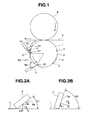
Fig. 1 is a view showing an array of cylinders in the main part of a gravure printing press according to the first embodiment of the present invention; -
Fig. 2A is a side view showing a first doctor blade having a contact angle θ1 with the circumferential surface of a gravure plate cylinder, that is less than 45°; -
Fig. 2B is a side view showing a second doctor blade having a contact angle θ2 with the circumferential surface of the gravure plate cylinder, that is more than 45°; -
Fig. 3 is a view showing an array of cylinders in the main part of a gravure printing press according to the second embodiment of the present invention; -
Figs. 4A to 4D are views for explaining an ink transfer operation by a blanket cylinder shown inFig. 3 ; -
Fig. 5 is a side view showing a gravure plate cylinder according to the third embodiment of the present invention; and -
Fig. 6 is a view for explaining an ink scraping operation by a doctor blade shown inFig. 5 . - The first embodiment of the present invention will be described first with reference to
Figs. 1, 2A, and 2B . As shown inFig. 1 , animpression cylinder 4 is opposed to agravure plate cylinder 1 while their circumferential surfaces are kept in contact with each other. Thegravure plate cylinder 1 includes, on its circumferential surface, a large number ofrecesses 2 that form image areas upon being filled with ink.Ink 3 containing sliver paste (conductive paste) for an electrode is supplied from a chamber typeink supply device 12 onto the circumferential surface of thegravure plate cylinder 1 including therecesses 2. A sheet-like printing object 5 is printed by the ink on thegravure plate cylinder 1 upon passing between thegravure plate cylinder 1 and theimpression cylinder 4. - In this arrangement, when the
ink 3 is supplied from theink supply device 12 onto the circumferential surface of thegravure plate cylinder 1, it fills therecesses 2 in thegravure plate cylinder 1. The ink which fills therecesses 2 is transferred onto theprinting object 5 when therecesses 2 are opposed to theimpression cylinder 4, thereby printing electrical wiring lines on theprinting object 5. - A holding member (not shown) holds first and
second doctor blades gravure plate cylinder 1. Thedoctor blade 6 is arranged upstream of thedoctor blade 7 in the rotation direction of thegravure plate cylinder 1 with a predetermined spacing from it. - The applicant of this invention repeated various kinds of experiments, and the experimental results revealed that as the contact angle between the doctor blade and the circumferential surface of the gravure plate cylinder gets larger, the function of scraping away ink improves but the function of filling the recesses with ink degrades. The experimental results also revealed that as the contact angle between the doctor blade and the circumferential surface of the gravure plate cylinder gets smaller, the function of filling ink in the recesses improves but the function of scraping away ink degrades.
- The present invention has been made in consideration of the above-mentioned findings, and proposes that the contact angles between the circumferential surface of the
gravure plate cylinder 1 and the first andsecond doctor blades doctor blade 6 with the circumferential surface of thegravure plate cylinder 1 is set less than 45°, and a contact angle θ2 of thedoctor blade 7 with the circumferential surface of thegravure plate cylinder 1 is set more than 45°. - Note that the contact angle θ1 means the angle formed between the
doctor blade 6 and a segment A1 - A2, located upstream in the rotation direction of thegravure plate cylinder 1, on a tangent to the circumferential surface of thegravure plate cylinder 1 at a point A1 where the distal end of thedoctor blade 6 comes into contact with this circumferential surface. Also, the contact angle θ2 means the angle formed between thedoctor blade 7 and a segment B1 - B2, located upstream in the rotation direction of thegravure plate cylinder 1, on a tangent to the circumferential surface of thegravure plate cylinder 1 at a point B1 where the distal end of thedoctor blade 7 comes into contact with this circumferential surface. - The relationships between the contact angles of the
doctor blades gravure plate cylinder 1 and the functions of thedoctor blades Figs. 2A and 2B . As shown inFig. 2A , when the contact angle θ1 is relatively small, the downward tilt of a vector V representing the force acting on thegravure plate cylinder 1 from ablade surface 6a of thedoctor blade 6 is large. In this case, a force V1 with which thedoctor blade 6 fills therecesses 2 in thegravure plate cylinder 1 with the ink is large. On the other hand, a force V2 with which thedoctor blade 6 scrapes away the ink adhering on the circumferential surface of thegravure plate cylinder 1 is small. - In contrast, as shown in
Fig. 2B , when the contact angle θ2 is relatively large, the downward tilt of a vector V representing the force acting on thegravure plate cylinder 1 from ablade surface 7a of thedoctor blade 7 is small. In this case, a force V1 with which thedoctor blade 7 fills therecesses 2 in thegravure plate cylinder 1 with the ink is small. On the other hand, a force V2 with which thedoctor blade 7 scrapes away the ink adhering on the circumferential surface of thegravure plate cylinder 1 is large. - The magnitudes of the force V1 which acts to fill the ink and the force V2 which acts to scrape away the ink, mentioned above, reverse as the contact angle reaches 45°. That is, when the contact angle is less than 45°, the ink filling force produced by the doctor blade is large. However, when the contact angle is more than 45°, the ink scraping force produced by the doctor blade is large.
- As described above, the
gravure plate cylinder 1 according to the present invention is provided with thefirst doctor blade 6 having a contact angle θ1 with thegravure plate cylinder 1, that is set less than 45° (0° < θ1 < 45°), and thesecond doctor blade 7 having a contact angle θ2 with thegravure plate cylinder 1, that is set more than 45°. The contact angle θ1 need only satisfy 0° < θ1 < 45°, and the contact angle θ2 need only satisfy 45° < θ2 < 90°. - In the gravure printing press with the above-mentioned arrangement, the
ink 3 supplied from theink supply device 12 onto the circumferential surface of thegravure plate cylinder 1 is first pushed into therecesses 2 by thedoctor blade 6 capable of producing a large filling force, thereby reliably filling therecesses 2 with a necessary amount of ink. Especially when ink containing silver paste is used, the ink itself has high viscosity and a heavy weight, so insufficient filling in therecesses 2 is likely to occur. Therefore, because thedoctor blade 6 which exclusively performs an ink filling operation is provided separately from that which performs an ink scraping operation, insufficient filling can be reliably compensated for. - After the
doctor blade 6 performs a filling operation, thedoctor blade 7 reliably scrapes away superfluous ink adhering on the circumferential surface of thegravure plate cylinder 1. In this case as well, when ink containing silver paste is used, the ink itself has high viscosity and a heavy weight and this makes it hard to scrape away the ink. However, the force V2 with which thedoctor blade 7 scrapes away the ink is so large that superfluous ink adhering on the circumferential surface of thegravure plate cylinder 1 can be reliably scraped away. Thus, ink which reliably fills therecesses 2 only by a necessary amount is transferred onto theprinting object 5, and superfluous ink adhering on the circumferential surface of thegravure plate cylinder 1 is reliably scraped away. As a result, printing is performed with a sufficient amount of ink and no ink is transferred onto the non-image areas, thus improving the printing quality. - Also, because the
doctor blade 6 is provided upstream of thedoctor blade 7 in the rotation direction of thegravure plate cylinder 1, therecesses 2 can be reliably filled with theink 3. After that, thedoctor blade 7 can reliably scrape away theink 3 which does not fill therecesses 2. - The second embodiment of the present invention will be described next with reference to
Figs. 3 and4A to 4D . In the second embodiment, ablanket cylinder 10 is opposed to agravure plate cylinder 1 and animpression cylinder 4 while their circumferential surfaces are kept in contact with each other to perform printing when aprinting object 5 passes between theblanket cylinder 10 and theimpression cylinder 4. A blanket (not shown) mounted on the circumferential surface of theblanket cylinder 10 is made of a material with a low surface energy, such as silicone. In the second embodiment, contact angles θ1 and θ2 ofdoctor blades doctor blade 6 with the circumferential surface of thegravure plate cylinder 1 is set less than 45°, and the contact angle θ2 of thedoctor blade 7 with the circumferential surface of thegravure plate cylinder 1 is set more than 45°. - Because the
blanket cylinder 10 is more likely to elastically deform, it partly entersrecesses 2 in thegravure plate cylinder 1, as shown inFig. 4A , upon receivingink 3 from thegravure plate cylinder 1. Thus, the ink in therecesses 2 is pushed by theblanket cylinder 10, thereby bringing theink 3 into tight contact with the surface of theblanket cylinder 10. As a result, theink 3 transferred onto theblanket cylinder 10 is reliably transferred onto the surface of theblanket cylinder 10 to reproduce the image on the plate, as shown inFig. 4B . - The
ink 3 transferred onto theblanket cylinder 10 is opposed to theprinting object 5 with rotation of theblanket cylinder 10, as shown inFig. 4C . Theink 3 is pressed against theprinting object 5 by the action of theimpression cylinder 4, thereby transferring it onto theprinting object 5, as shown inFig. 4D . At this time, because theblanket cylinder 10 deforms and has a low surface energy, the separation characteristics of the ink are so good that theink 3 does not stay behind on the surface of theblanket cylinder 10. In this manner, almost the entire amount ofink 3 on theblanket cylinder 10 is reliably transferred onto theprinting object 5, so aprinting surface 3a of theink 3 becomes smooth. As a result, the entire surface of theprinting object 5, including the portions to be printed by theink 3, becomes smooth, thus improving the printing quality. - The third embodiment of the present invention will be described next with reference to
Figs. 5 and 6 . The feature of the third embodiment lies in that a reverse-angle doctor blade is used as adoctor blade 7, that is, a contact angle θ2 of thedoctor blade 7 is set more than 90°, as shown inFig. 5 . Note that a contact angle θ1 of adoctor blade 6 is set less than 45°, as in the first and second embodiments. - The reverse-angle doctor blade can be more efficiently, effectively prevented from falling into
recesses 2 while strengthening the ink scraping force, as compared with a doctor blade with a contact angle θ2 of 45° to 90°. Accordingly, because the reverse-angle doctor blade enters therecesses 2 only by a small amount upon bending, and the ink which has already filled therecesses 2 is not scraped away, as shown inFig. 6 . Therefore,ink 3 which fills therecesses 2 is stored intact, and superfluous ink adhering on the circumferential surface of agravure plate cylinder 1 is reliably scraped away. As a result, no ink is transferred onto the non-image areas, thus improving the printing quality. - Although an example in which each of the
doctor blade 6 having a contact angle of less than 45° and thedoctor blade 7 having a contact angle of more than 45° is provided in one portion has been described in each of the above-mentioned embodiments, one or both of thedoctor blades more doctor blades gravure plate cylinder 1. - Also, although the
doctor blade 6 is arranged upstream of thedoctor blade 7 in the rotation direction of thegravure plate cylinder 1, thedoctor blade 7 may be arranged upstream of thedoctor blade 6 in the rotation direction of thegravure plate cylinder 1. - Moreover, although silver paste has been taken as an example of the component contained in the
ink 3, the present invention is not limited to this. For example, the component contained in theink 3 may be carbon which has so small a particle diameter that it is hard for the doctor blade to scrape away it, and need only be a paste with high viscosity. Although the blanket mounted on theblanket cylinder 10 is made of silicone, the present invention is not limited to this. For example, this blanket may be made of PTFE (polytetrafluoroethylene) or PVDF (polyvinylidene fluoride), and need only be a material with a low surface energy and good separation characteristics. - As has been described above, according to the present invention, because the first blade can reliably fill the recesses in the gravure plate cylinder with the ink, a necessary amount of ink is transferred onto the printing object. Also, the second blade reliably scrapes away the ink in the non-image areas, thus improving the printing quality.
Claims (8)
- A gravure printing press characterized by comprising:a gravure plate cylinder (1) which includes, on a circumferential surface thereof, a plurality of recesses (2) that form image areas upon being filled with ink (3);an ink supply device (12) which supplies the ink onto the circumferential surface of said gravure plate cylinder;a first blade (6) which comes into contact with the circumferential surface of said gravure plate cylinder at a contact angle of less than 45°; anda second blade (7) which comes into contact with the circumferential surface of said gravure plate cylinder at a contact angle of more than 45°.
- An apparatus according to claim 1, wherein
said first blade is arranged upstream of said second blade in a rotation direction of said gravure plate cylinder. - An apparatus according to claim 1, wherein
the contact angle of said second blade with the circumferential surface of said gravure plate cylinder is set more than 90°. - An apparatus according to claim 1, further comprising:an impression cylinder (4) which is opposed to said gravure plate cylinder while circumferential surfaces thereof are kept in contact with each other,wherein printing is performed when a printing object (5) passes between said gravure plate cylinder and said impression cylinder.
- An apparatus according to claim 1, further comprising:a blanket cylinder (10) which is opposed to said gravure plate cylinder while circumferential surfaces thereof are kept in contact with each other; andan impression cylinder (4) which is opposed to said blanket cylinder,wherein printing is performed when a printing object (5) passes between said blanket cylinder and said impression cylinder.
- An apparatus according to claim 1, wherein
said first blade fills said plurality of recesses with the ink, and said second blade scrapes away the ink which does not fill said plurality of recesses. - An apparatus according to claim 1, wherein
the ink supplied from said ink supply device contains a paste with high viscosity. - An apparatus according to claim 7, wherein
the paste which is contained in the ink and has high viscosity includes silver paste.
Applications Claiming Priority (1)
| Application Number | Priority Date | Filing Date | Title |
|---|---|---|---|
| JP2010102110A JP2011230348A (en) | 2010-04-27 | 2010-04-27 | Gravure printing machine |
Publications (1)
| Publication Number | Publication Date |
|---|---|
| EP2383119A1 true EP2383119A1 (en) | 2011-11-02 |
Family
ID=44065397
Family Applications (1)
| Application Number | Title | Priority Date | Filing Date |
|---|---|---|---|
| EP11003291A Withdrawn EP2383119A1 (en) | 2010-04-27 | 2011-04-19 | Gravure printing press |
Country Status (6)
| Country | Link |
|---|---|
| US (1) | US20110259220A1 (en) |
| EP (1) | EP2383119A1 (en) |
| JP (1) | JP2011230348A (en) |
| KR (1) | KR20110119561A (en) |
| CN (1) | CN102233709A (en) |
| TW (1) | TW201206714A (en) |
Cited By (1)
| Publication number | Priority date | Publication date | Assignee | Title |
|---|---|---|---|---|
| EP4159463A1 (en) | 2021-10-04 | 2023-04-05 | Hueck Folien Gesellschaft m.b.H. | Gravure printing cylinder for microprinting |
Families Citing this family (8)
| Publication number | Priority date | Publication date | Assignee | Title |
|---|---|---|---|---|
| JP6112502B2 (en) * | 2012-10-05 | 2017-04-12 | 株式会社小森コーポレーション | Gravure offset printing machine |
| JP6213111B2 (en) * | 2013-09-30 | 2017-10-18 | 大日本印刷株式会社 | Gravure printing machine and gravure printing method |
| JP6233807B2 (en) * | 2014-02-26 | 2017-11-22 | 株式会社小森コーポレーション | Gravure printing machine and operation method of gravure printing machine |
| US9579878B1 (en) * | 2015-10-30 | 2017-02-28 | Industrial Technology Research Institute | Gravure printing system and method of using the same |
| CN106626726A (en) * | 2016-12-25 | 2017-05-10 | 天津荣彩3D科技有限公司 | Novel intaglio printing coating device |
| WO2018193542A1 (en) * | 2017-04-19 | 2018-10-25 | カナロア・トレード株式会社 | Gravure coater |
| CN108582970A (en) * | 2018-04-21 | 2018-09-28 | 海宁市天祥包装机械厂 | Intaglio press |
| CN117301697A (en) * | 2022-06-22 | 2023-12-29 | 至善实业股份有限公司 | Methods to improve the printing quality of gravure printing machines |
Citations (5)
| Publication number | Priority date | Publication date | Assignee | Title |
|---|---|---|---|---|
| US4009657A (en) * | 1975-02-25 | 1977-03-01 | Scott Paper Company | Apparatus for applying fluid to an intaglio roll for transfer to a soft, absorbent fibrous web |
| EP0320226A2 (en) * | 1987-12-07 | 1989-06-14 | Robert Temple Bowden | Prewipe blade |
| US5112653A (en) * | 1989-07-03 | 1992-05-12 | Consolidated Papers, Inc. | Method of and apparatus for coating high speed traveling webs |
| JPH0724990A (en) | 1993-07-13 | 1995-01-27 | Komori Corp | Doctor blade device for gravure printing machine |
| US6360660B1 (en) * | 1998-11-25 | 2002-03-26 | Allison Tech Sales Incorporated | Doctor blade systems |
Family Cites Families (5)
| Publication number | Priority date | Publication date | Assignee | Title |
|---|---|---|---|---|
| JP3158718B2 (en) * | 1992-09-28 | 2001-04-23 | ソニー株式会社 | Printing equipment |
| JPH0872218A (en) * | 1994-09-05 | 1996-03-19 | Rengo Co Ltd | Printing roll and printing apparatus |
| JP2002321336A (en) * | 2001-04-26 | 2002-11-05 | Dainippon Printing Co Ltd | Intaglio press |
| JP2004111822A (en) * | 2002-09-20 | 2004-04-08 | Sumitomo Rubber Ind Ltd | Method for manufacturing translucent electromagnetic wave shielding member |
| JP4984433B2 (en) * | 2005-05-16 | 2012-07-25 | 大日本印刷株式会社 | Method for forming light emitting layer and method for producing organic light emitting device using the same |
-
2010
- 2010-04-27 JP JP2010102110A patent/JP2011230348A/en active Pending
-
2011
- 2011-04-15 TW TW100113157A patent/TW201206714A/en unknown
- 2011-04-19 EP EP11003291A patent/EP2383119A1/en not_active Withdrawn
- 2011-04-21 CN CN2011101043814A patent/CN102233709A/en active Pending
- 2011-04-25 KR KR1020110038665A patent/KR20110119561A/en not_active Ceased
- 2011-04-26 US US13/094,739 patent/US20110259220A1/en not_active Abandoned
Patent Citations (5)
| Publication number | Priority date | Publication date | Assignee | Title |
|---|---|---|---|---|
| US4009657A (en) * | 1975-02-25 | 1977-03-01 | Scott Paper Company | Apparatus for applying fluid to an intaglio roll for transfer to a soft, absorbent fibrous web |
| EP0320226A2 (en) * | 1987-12-07 | 1989-06-14 | Robert Temple Bowden | Prewipe blade |
| US5112653A (en) * | 1989-07-03 | 1992-05-12 | Consolidated Papers, Inc. | Method of and apparatus for coating high speed traveling webs |
| JPH0724990A (en) | 1993-07-13 | 1995-01-27 | Komori Corp | Doctor blade device for gravure printing machine |
| US6360660B1 (en) * | 1998-11-25 | 2002-03-26 | Allison Tech Sales Incorporated | Doctor blade systems |
Cited By (2)
| Publication number | Priority date | Publication date | Assignee | Title |
|---|---|---|---|---|
| EP4159463A1 (en) | 2021-10-04 | 2023-04-05 | Hueck Folien Gesellschaft m.b.H. | Gravure printing cylinder for microprinting |
| WO2023057279A1 (en) | 2021-10-04 | 2023-04-13 | Hueck Folien Gesellschaft M.B.H. | Intaglio printing cylinder for microprinting |
Also Published As
| Publication number | Publication date |
|---|---|
| US20110259220A1 (en) | 2011-10-27 |
| TW201206714A (en) | 2012-02-16 |
| CN102233709A (en) | 2011-11-09 |
| KR20110119561A (en) | 2011-11-02 |
| JP2011230348A (en) | 2011-11-17 |
Similar Documents
| Publication | Publication Date | Title |
|---|---|---|
| US20110259220A1 (en) | Gravure printing press | |
| JP5438593B2 (en) | Gravure offset printing machine | |
| US20080083367A1 (en) | Gravure coating apparatus | |
| EP1020304A3 (en) | Offset printing method and printing apparatus using the same | |
| EP1936565A3 (en) | Method for decimation of images | |
| EP2136291A3 (en) | Image forming system, image forming method and image forming apparatus | |
| JP2007261270A (en) | Anilox printing unit | |
| EP1731319A3 (en) | Inkjet printing apparatus, inkjet printing method and inkjet printing system | |
| EP1939006B1 (en) | Method of printing | |
| CN105252883A (en) | Intelligent electronic intaglio-printing-roll printing system and plate making method | |
| CN203019801U (en) | Pressure resisting cylinder type printing device | |
| EP1712356A3 (en) | System and method for pad printing | |
| CN216683680U (en) | Energy-saving screen printer | |
| CA2717444A1 (en) | Rotating cliche pad printer | |
| US20190047311A1 (en) | Printing plate, laminated ceramic electronic component producing method, and printer | |
| CN102416760B (en) | To version measuring cell | |
| JP2002321336A (en) | Intaglio press | |
| KR20140100628A (en) | The Roll to Roll printer equipped with inclined gravure cylinder and Electrolyte membrance and Separating film for battery using of it | |
| CN214294956U (en) | Ink scraping device of gravure printing machine | |
| CN114885508A (en) | Flexible integrated circuit production system and method | |
| CN101351339B (en) | Pad printing presses with pad attachment and printing pads | |
| JP5607421B2 (en) | Gravure offset printing machine | |
| CN115515792A (en) | Master roll for gravure printing, gravure printing device, and method for manufacturing multilayer ceramic capacitor | |
| CN110621504A (en) | Roller device and printing machine | |
| JP2015160397A (en) | Blanket for gravure offset printing and wiring pattern forming method using the same |
Legal Events
| Date | Code | Title | Description |
|---|---|---|---|
| AK | Designated contracting states |
Kind code of ref document: A1 Designated state(s): AL AT BE BG CH CY CZ DE DK EE ES FI FR GB GR HR HU IE IS IT LI LT LU LV MC MK MT NL NO PL PT RO RS SE SI SK SM TR |
|
| AX | Request for extension of the european patent |
Extension state: BA ME |
|
| PUAI | Public reference made under article 153(3) epc to a published international application that has entered the european phase |
Free format text: ORIGINAL CODE: 0009012 |
|
| STAA | Information on the status of an ep patent application or granted ep patent |
Free format text: STATUS: THE APPLICATION IS DEEMED TO BE WITHDRAWN |
|
| 18D | Application deemed to be withdrawn |
Effective date: 20120503 |