EP2383066A2 - Sonotrodenhalterungssystem - Google Patents
Sonotrodenhalterungssystem Download PDFInfo
- Publication number
- EP2383066A2 EP2383066A2 EP11003460A EP11003460A EP2383066A2 EP 2383066 A2 EP2383066 A2 EP 2383066A2 EP 11003460 A EP11003460 A EP 11003460A EP 11003460 A EP11003460 A EP 11003460A EP 2383066 A2 EP2383066 A2 EP 2383066A2
- Authority
- EP
- European Patent Office
- Prior art keywords
- sonotrode
- web
- arms
- shaped bracket
- clamped
- Prior art date
- Legal status (The legal status is an assumption and is not a legal conclusion. Google has not performed a legal analysis and makes no representation as to the accuracy of the status listed.)
- Withdrawn
Links
- 239000000463 material Substances 0.000 claims abstract description 10
- 238000007789 sealing Methods 0.000 claims abstract description 5
- 238000002604 ultrasonography Methods 0.000 claims description 17
- 239000004744 fabric Substances 0.000 claims description 5
- 239000010408 film Substances 0.000 claims description 5
- 239000004745 nonwoven fabric Substances 0.000 claims description 5
- 239000004033 plastic Substances 0.000 claims description 5
- 229920003023 plastic Polymers 0.000 claims description 5
- 239000004753 textile Substances 0.000 claims description 5
- 238000004049 embossing Methods 0.000 claims description 4
- 238000005304 joining Methods 0.000 claims description 4
- 230000000284 resting effect Effects 0.000 claims 1
- 238000007493 shaping process Methods 0.000 abstract description 3
- 230000015572 biosynthetic process Effects 0.000 abstract 1
- 230000001771 impaired effect Effects 0.000 abstract 1
- 230000003534 oscillatory effect Effects 0.000 description 9
- 239000002131 composite material Substances 0.000 description 3
- 230000010355 oscillation Effects 0.000 description 3
- 230000009466 transformation Effects 0.000 description 3
- 238000003466 welding Methods 0.000 description 2
- 238000010521 absorption reaction Methods 0.000 description 1
- 238000010276 construction Methods 0.000 description 1
- 230000003993 interaction Effects 0.000 description 1
- 238000004519 manufacturing process Methods 0.000 description 1
- 238000004806 packaging method and process Methods 0.000 description 1
- 239000007787 solid Substances 0.000 description 1
- 230000004936 stimulating effect Effects 0.000 description 1
- 239000012815 thermoplastic material Substances 0.000 description 1
Images

Classifications
-
- B—PERFORMING OPERATIONS; TRANSPORTING
- B23—MACHINE TOOLS; METAL-WORKING NOT OTHERWISE PROVIDED FOR
- B23K—SOLDERING OR UNSOLDERING; WELDING; CLADDING OR PLATING BY SOLDERING OR WELDING; CUTTING BY APPLYING HEAT LOCALLY, e.g. FLAME CUTTING; WORKING BY LASER BEAM
- B23K20/00—Non-electric welding by applying impact or other pressure, with or without the application of heat, e.g. cladding or plating
- B23K20/10—Non-electric welding by applying impact or other pressure, with or without the application of heat, e.g. cladding or plating making use of vibrations, e.g. ultrasonic welding
-
- B—PERFORMING OPERATIONS; TRANSPORTING
- B06—GENERATING OR TRANSMITTING MECHANICAL VIBRATIONS IN GENERAL
- B06B—METHODS OR APPARATUS FOR GENERATING OR TRANSMITTING MECHANICAL VIBRATIONS OF INFRASONIC, SONIC, OR ULTRASONIC FREQUENCY, e.g. FOR PERFORMING MECHANICAL WORK IN GENERAL
- B06B3/00—Methods or apparatus specially adapted for transmitting mechanical vibrations of infrasonic, sonic, or ultrasonic frequency
-
- B—PERFORMING OPERATIONS; TRANSPORTING
- B26—HAND CUTTING TOOLS; CUTTING; SEVERING
- B26D—CUTTING; DETAILS COMMON TO MACHINES FOR PERFORATING, PUNCHING, CUTTING-OUT, STAMPING-OUT OR SEVERING
- B26D7/00—Details of apparatus for cutting, cutting-out, stamping-out, punching, perforating, or severing by means other than cutting
- B26D7/08—Means for treating work or cutting member to facilitate cutting
- B26D7/086—Means for treating work or cutting member to facilitate cutting by vibrating, e.g. ultrasonically
-
- B—PERFORMING OPERATIONS; TRANSPORTING
- B26—HAND CUTTING TOOLS; CUTTING; SEVERING
- B26D—CUTTING; DETAILS COMMON TO MACHINES FOR PERFORATING, PUNCHING, CUTTING-OUT, STAMPING-OUT OR SEVERING
- B26D7/00—Details of apparatus for cutting, cutting-out, stamping-out, punching, perforating, or severing by means other than cutting
-
- B—PERFORMING OPERATIONS; TRANSPORTING
- B29—WORKING OF PLASTICS; WORKING OF SUBSTANCES IN A PLASTIC STATE IN GENERAL
- B29C—SHAPING OR JOINING OF PLASTICS; SHAPING OF MATERIAL IN A PLASTIC STATE, NOT OTHERWISE PROVIDED FOR; AFTER-TREATMENT OF THE SHAPED PRODUCTS, e.g. REPAIRING
- B29C65/00—Joining or sealing of preformed parts, e.g. welding of plastics materials; Apparatus therefor
- B29C65/02—Joining or sealing of preformed parts, e.g. welding of plastics materials; Apparatus therefor by heating, with or without pressure
- B29C65/08—Joining or sealing of preformed parts, e.g. welding of plastics materials; Apparatus therefor by heating, with or without pressure using ultrasonic vibrations
-
- B—PERFORMING OPERATIONS; TRANSPORTING
- B29—WORKING OF PLASTICS; WORKING OF SUBSTANCES IN A PLASTIC STATE IN GENERAL
- B29C—SHAPING OR JOINING OF PLASTICS; SHAPING OF MATERIAL IN A PLASTIC STATE, NOT OTHERWISE PROVIDED FOR; AFTER-TREATMENT OF THE SHAPED PRODUCTS, e.g. REPAIRING
- B29C66/00—General aspects of processes or apparatus for joining preformed parts
- B29C66/80—General aspects of machine operations or constructions and parts thereof
- B29C66/81—General aspects of the pressing elements, i.e. the elements applying pressure on the parts to be joined in the area to be joined, e.g. the welding jaws or clamps
- B29C66/814—General aspects of the pressing elements, i.e. the elements applying pressure on the parts to be joined in the area to be joined, e.g. the welding jaws or clamps characterised by the design of the pressing elements, e.g. of the welding jaws or clamps
- B29C66/8145—General aspects of the pressing elements, i.e. the elements applying pressure on the parts to be joined in the area to be joined, e.g. the welding jaws or clamps characterised by the design of the pressing elements, e.g. of the welding jaws or clamps characterised by the constructional aspects of the pressing elements, e.g. of the welding jaws or clamps
-
- B—PERFORMING OPERATIONS; TRANSPORTING
- B29—WORKING OF PLASTICS; WORKING OF SUBSTANCES IN A PLASTIC STATE IN GENERAL
- B29C—SHAPING OR JOINING OF PLASTICS; SHAPING OF MATERIAL IN A PLASTIC STATE, NOT OTHERWISE PROVIDED FOR; AFTER-TREATMENT OF THE SHAPED PRODUCTS, e.g. REPAIRING
- B29C66/00—General aspects of processes or apparatus for joining preformed parts
- B29C66/80—General aspects of machine operations or constructions and parts thereof
- B29C66/81—General aspects of the pressing elements, i.e. the elements applying pressure on the parts to be joined in the area to be joined, e.g. the welding jaws or clamps
- B29C66/816—General aspects of the pressing elements, i.e. the elements applying pressure on the parts to be joined in the area to be joined, e.g. the welding jaws or clamps characterised by the mounting of the pressing elements, e.g. of the welding jaws or clamps
- B29C66/8167—Quick change joining tools or surfaces
-
- Y—GENERAL TAGGING OF NEW TECHNOLOGICAL DEVELOPMENTS; GENERAL TAGGING OF CROSS-SECTIONAL TECHNOLOGIES SPANNING OVER SEVERAL SECTIONS OF THE IPC; TECHNICAL SUBJECTS COVERED BY FORMER USPC CROSS-REFERENCE ART COLLECTIONS [XRACs] AND DIGESTS
- Y10—TECHNICAL SUBJECTS COVERED BY FORMER USPC
- Y10T—TECHNICAL SUBJECTS COVERED BY FORMER US CLASSIFICATION
- Y10T156/00—Adhesive bonding and miscellaneous chemical manufacture
- Y10T156/12—Surface bonding means and/or assembly means with cutting, punching, piercing, severing or tearing
Definitions
- the invention relates to a system for supporting a vibrating structure comprising a sonotrode of an ultrasound system, and more particularly to a sonotrode mounting system. It further relates to an apparatus comprising an ultrasound system with such a sonotrode holder system for sealing, joining, separating, perforating and / or embossing materials such as, in particular, plastics, films, nonwovens, fabrics / textiles and / or paper.
- Ultrasound systems with at least one oscillating structure having a sonotrode and a converter, an ultrasonic generator stimulating the converter and an anvil opposite the sonotrode are already known as such.
- the ultrasonic generator generates an alternating voltage, which is converted by the converter usually according to the piezoelectric transducer principle into a mechanical vibration.
- this mechanical vibration is transmitted to the materials to be processed.
- the material to be connected to the contact surfaces is plasticized by the interplay of the physical conditions between the anvil and sonotrode, that is to say in particular sound reflection, sound absorption and boundary surface friction, whereby the relevant materials, in particular plastics, films, nonwovens, fabric / Textiles and / or paper to be welded together.
- the relevant materials in particular plastics, films, nonwovens, fabric / Textiles and / or paper to be welded together.
- Prerequisite for the welding is a small minimum proportion of a thermoplastic material.
- the oscillatory structure of the ultrasound system can in principle also comprise an amplitude transformation piece connected between the converter and the sonotrode.
- the contact surface of the sonotrode which comes into contact with the materials to be processed can in particular be flat.
- the welding contours, etc. are provided on the anvil. Sonotrode and anvil can be moved towards and away from each other. It is also possible to arrange several sonotrodes or oscillating structures next to one another.
- auxiliary boosters which are each connected at one end fixed to the sonotrode and the other end each capable of oscillating and the sonotrode are inserted supporting in an opening of a holder.
- the auxiliary boosters can be supported on a vibration node occurring in these occurring in the vibration structure longitudinal vibration on the holder.
- the invention has for its object to provide a sonotrode system that allows a reliable, stable mounting of the oscillatory structure of an ultrasound system with the simplest possible, robust construction.
- the replacement of a respective vibrating structure or parts of this vibrating structure is to be facilitated from a composite.
- a correspondingly improved device of the type mentioned is to be created.
- a sonotrode mounting system with at least one supportable on a support generally U-shaped bracket comprising a web and two legs, each spring-tiltable about a node provided in the web area and between which an ultrasonic sonotrode can be clamped, wherein at least the free ends of the legs bear against this sonotrode when the sonotrode is clamped, and the clamp can be supported on the support in the web region.
- the sonotrode or the vibration-bearing parts can be designed relatively massive, whereby a robust support is achieved. Under mechanical stress occur at most slight changes in shape of the clip.
- a simpler exchange of a respective oscillating structure or of parts of this oscillatory structure from a composite is now also possible.
- the free ends of the legs of a respective generally U-shaped chamber are each provided with a notch in which engages a provided on the sonotrode approach with clamped sonotrode.
- the approach may be relatively small and be formed for example by a particular small chamfered surface.
- the free ends of the legs of a respective generally U-shaped brackets may each be provided with a corresponding projection which engages in a corresponding notch of the sonotrode with a strained sonotrode.
- the approach is preferably relatively small again.
- the respective cooperating lugs and notches are preferably dimensioned such that when the sonotrode is clamped in particular due to Transverse oscillations of the sonotrode occurring tilting movements of the legs are not hindered by the node.
- the clip is preferably supported in the node of the tilting movements of the carrier.
- the tilting movements of the leg supporting recesses are provided in the web region of a respective generally U-shaped bracket.
- the web of a respective generally U-shaped bracket is subdivided into two web sections respectively associated with one of the two legs and the web sections in particular detachably connectable to one another, for example to form the U-shaped clip. are pivotable.
- each web portion may each be provided a recess supporting the tilting movement of the associated leg.
- the free ends of the limbs of a respective generally U-shaped clamp engage in or on the sonotrode in the vibration node of the longitudinal vibration generated in the sonotrode.
- the sonotrode mounting system ensures a stable mounting of the oscillation structure of an ultrasound system.
- the holder preferably engages in the vibration node of the longitudinal vibration occurring in the sonotrode, where it is braced can be.
- the transverse expansion movement of the sonotrode occurring there requires a co-movement of the generally U-shaped clamp in the form of a transversal oscillation.
- By appropriate shaping of the holder is formed at the foot, ie in the web area of the generally U-shaped bracket a tilting movement.
- the clip is preferably supported or fixed at the junction of this tilting movement on the carrier, for example a carrier plate.
- the holder is therefore preferably stored at the junction of a tilting vibration.
- the above-mentioned object is also achieved by a device for sealing, joining, separating, perforating and / or embossing materials such as, in particular, plastics, films, nonwovens, fabrics / textiles and / or paper, with an ultrasound system that has at least one sonotrode and a converter comprising the oscillating structure, an ultrasonic generator exciting the converter, an anvil associated with the sonotrode, and a sonotrode mounting system associated with the sonotrode, wherein the free ends of the legs of a respective generally U-shaped bracket preferably at the vibration node of the longitudinal vibration generated at the sonotrode Sonotrode abut or engage with this.
- an ultrasound system that has at least one sonotrode and a converter comprising the oscillating structure, an ultrasonic generator exciting the converter, an anvil associated with the sonotrode, and a sonotrode mounting system associated with the sonotrode, wherein the free ends of the legs of a respective generally U-shaped bracket preferably at the vibration node of the longitudinal vibration generated at
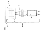
- Fig. 1 shows a schematic representation of an exemplary embodiment of an ultrasound system 10 of a device for sealing, joining, separating, perforating and / or embossing of materials such as in particular plastics, films, nonwovens, fabrics / textiles and / or paper, including the production of packaging suitable is.
- the ultrasound system 10 comprises at least one oscillating structure 18 having a sonotrode 12, a converter 14 and optionally an amplitude transformation piece 16, an ultrasound generator (not shown) exciting the converter 14 and an anvil 20 opposite the sonotrode 12.
- the sonotrode 12 and the anvil 20 may contact each other be moved to and away from each other.
- Fig. 2 shows a schematic perspective view of an exemplary embodiment of a sonotrode support system 22 according to the invention, which may for example be associated with the sonotrode 12 of such an ultrasound system 10, as shown in the Fig. 1 is shown.
- the sonotrode support system 22 comprises at least one generally U-shaped bracket 24, which can be supported on a support (not shown), with a web 26 and two limbs 28 which can each be resiliently tilted about a node 30 provided in the region of the web 26 and between which an ultrasound Sonotrode 12 is clamped, with at clamped sonotrode 12 at least the free ends 28 'of the legs 28 abut against this sonotrode 12 and engage with this and the clip 24 is supported in the web area on the carrier.
- the sonotrode 12 may have a generally cuboidal, elongated shape, and the two legs 28 of a respective bracket 24 may extend at two opposite longitudinal sides 38 of the sonotrode 12 generally perpendicular to the longitudinal axis of the sonotrode between these clamped sonotrode 12.
- the web 26 of the generally U-shaped clamp 24 is arranged on the sonotrode side 42 opposite the contact side 40 of the sonotrode 12 which comes into contact with the materials to be processed. Between this contact side 40 opposite Sonotrodenseite 42 and the web 26 of the bracket 24, a free space 44 is provided.
- Fig. 3 in which the sonotrode support system 22 according to Fig. 2 is shown in a schematic cross-sectional representation, in the present case, the free ends 28 'of the legs 28 of a respective generally U-shaped bracket 24, for example, each provided with a notch 32, engages in the clamped sonotrode 12 provided on the sonotrode 12 lug 34 ,
- the respective cooperating lugs 34 and notches 32 are dimensioned such that the tilting movements of the legs 28 around the node 30 that occur when the sonotrode 12 is clamped in are not hindered.
- a respective generally U-shaped bracket 24 is preferably mounted in the node 30 of the tilting movements or supported on the carrier.
- these recesses 36 may be introduced in particular from opposite sides of the web 26 forth and each extending parallel to the sonotrode longitudinal direction.
- the web 26 of a respective generally U-shaped bracket 24 may be divided into two each one of the two legs 28 associated web portions 26 ', 26 ", which are in particular releasably connectable to form the U-shaped bracket 24 and its web 26. These web sections 26 ', 26 "can be screwed together, for example. As based on the FIGS. 2 and 3 can be seen, in each web portion 26 '26 "each one the tilting movement of the associated leg 28 supporting recess 36 is provided.
- the free ends 28 'of the legs 28 of a respective generally U-shaped bracket 24 preferably engage the vibration node of the longitudinal vibration generated in the sonotrode 12 at the sonotrode 12. In the present case, therefore, the projections 34 and notches 32 in Vibration node of the generated in the sonotrode 12 longitudinal vibration with each other.
- the web portions 26 ', 26 "forming the web 26 of a respective generally U-shaped bracket 24 can each be designed as a base-like foot adjoining the relevant end of the associated leg 28.
- the node 30 of the tilting movements is preferably located on the from the legs 28 side facing away from the web 26 and the web portions 26 ', 26 ". With this web surface facing away from the legs 28, a respective generally U-shaped bracket 24 can then be supported, for example, on a carrier, for example carrier plate.
- the holder engages in the vibration node of the longitudinal vibration generated in the sonotrode at the sonotrode and is braced there.
- the there, i. Occurring in the region of the free leg ends transverse expansion movement of the sonotrode causes a Mitbe admire the respective generally U-shaped bracket in the form of a transverse vibration.
- the respective generally U-shaped bracket may be located at the junction of this tilting movement, which may in particular be on the leg's opposite end surface, for example on a support, e.g. a support plate to be fixed.
- the parts carrying the oscillatory structure can be made more solid, which makes the mounting more robust.
- a respective generally U-shaped bracket is mounted in the node of the tilting vibration.
Landscapes
- Engineering & Computer Science (AREA)
- Mechanical Engineering (AREA)
- Life Sciences & Earth Sciences (AREA)
- Forests & Forestry (AREA)
- Lining Or Joining Of Plastics Or The Like (AREA)
- Treatment Of Fiber Materials (AREA)
- Pressure Welding/Diffusion-Bonding (AREA)
- Percussion Or Vibration Massage (AREA)
- Apparatuses For Generation Of Mechanical Vibrations (AREA)
Abstract
Description
- Die Erfindung betrifft ein System zur Halterung eines eine Sonotrode umfassenden Schwinggebildes eines Ultraschallsystems und insbesondere ein Sonotrodenhalterungssystem. Sie betrifft ferner eine ein Ultraschallsystem mit einem solchen Sonotrodenhalterungssystem umfassende Vorrichtung zum Siegeln, Verbinden, Trennen, Perforieren und/oder Prägen von Materialien wie insbesondere Kunststoffen, Folien, Vliesen, Geweben/Textilien und/oder Papier.
- Ultraschallsysteme mit wenigstens einem eine Sonotrode und einen Konverter aufweisenden Schwinggebilde, einem den Konverter anregenden Ultraschallgenerator sowie einem der Sonotrode gegenüberliegenden Amboss sind als solche bereits bekannt. Dabei erzeugt der Ultraschallgenerator eine Wechselspannung, die vom Konverter in der Regel nach dem piezoelektrischen Wandlerprinzip in eine mechanische Schwingung umgewandelt wird. Über das angekoppelte Schwinggebilde wird diese mechanische Schwingung auf die zu bearbeitenden Materialien übertragen. Soll beispielsweise eine Verbindung hergestellt werden, wird das zu verbindende Material an den Kontaktflächen durch das Zusammenspiel der physikalischen Gegebenheiten zwischen Amboss und Sonotrode, das heißt insbesondere Schallreflexion, Schallabsorption und Grenzflächenreibung plastifiziert, wodurch die betreffenden Materialien, insbesondere Kunststoffe, Folien, Vliese, Gewebe/Textilien und/oder Papier, miteinander verschweißt werden. Voraussetzung für das Verschweißen ist ein geringer Mindestanteil eines thermoplastischen Kunststoffes.
- Das Schwinggebilde des Ultraschallsystems kann grundsätzlich auch ein zwischen dem Konverter und die Sonotrode geschaltetes Amplitudentransformationsstück umfassen. Die mit den zu bearbeitenden Materialien in Berührung kommende Kontaktfläche der Sonotrode kann insbesondere eben sein. In diesem Fall sind zum Beispiel die Schweißkonturen usw. am Amboss vorgesehen. Sonotrode und Amboss können aufeinander zu und voneinander weg bewegt werden. Es können auch mehrere Sonotroden bzw. Schwinggebilde nebeneinander angeordnet werden.
- Bei einem aus der
DE 20 2004 003 917 U1 bekannten System zur Halterung des Schwinggebildes eines Ultraschallsystems sind an der Sonotrode wenigstens vier Hilfsbooster angeordnet, die mit einem Ende jeweils fest mit der Sonotrode verbunden sind und deren anderes Ende jeweils schwingfähig und die Sonotrode abstützend in eine Öffnung eines Halters eingesetzt sind. Dabei können die Hilfsbooster an einem in diesen auftretenden Schwingungsknoten der im Schwinggebilde entstehenden Longitudinalschwingung am Halter abgestützt sein. - Der Erfindung liegt die Aufgabe zugrunde, ein Sonotrodensystem zu schaffen, das bei möglichst einfachem, robustem Aufbau eine zuverlässige, stabile Halterung des Schwinggebildes eines Ultraschallsystems ermöglicht. Zudem soll der Austausch eines jeweiligen Schwinggebildes oder von Teilen dieses Schwinggebildes aus einem Verbund erleichtert werden. Überdies soll eine entsprechend verbesserte Vorrichtung der eingangs genannten Art geschaffen werden.
- Erfindungsgemäß wird diese Aufgabe gelöst durch ein Sonotrodenhalterungssystem mit wenigstens einer an einem Träger abstützbaren allgemein U-förmigen Klammer, die einen Steg und zwei Schenkel umfasst, die jeweils um einen im Stegbereich vorgesehenen Knotenpunkt federnd kippbar sind und zwischen die eine Ultraschall-Sonotrode einspannbar ist, wobei bei eingespannter Sonotrode zumindest die freien Enden der Schenkel an dieser Sonotrode anliegen und die Klammer im Stegbereich an dem Träger abstützbar ist.
- Aufgrund dieser Ausbildung ergibt sich ein insgesamt sehr stabiler Aufbau des Halterungssystems, womit die Betriebssicherheit entsprechend erhöht wird. Die die Sonotrode bzw. das Schwinggebilde tragenden Teile können relativ massiv ausgelegt werden, wodurch eine robuste Halterung erreicht wird. Unter mechanischer Belastung treten allenfalls geringe Formänderungen der Klammer auf. Zudem ist aufgrund der erfindungsgemäßen Ausgestaltung nunmehr auch ein einfacheres Austauschen eines jeweiligen Schwinggebildes oder von Teilen dieses Schwinggebildes aus einem Verbund möglich.
- Bevorzugt sind die freien Enden der Schenkel einer jeweiligen allgemein U-förmigen Kammer jeweils mit einer Kerbe versehen, in die bei eingespannter Sonotrode ein an der Sonotrode vorgesehener Ansatz eingreift. Dabei kann der Ansatz relativ klein und beispielsweise durch eine insbesondere kleine angefaste Fläche gebildet sein.
- Alternativ können jedoch auch die freien Enden der Schenkel einer jeweiligen allgemein U-förmigen Klammern jeweils mit einem entsprechenden Ansatz versehen sein, der bei angespannter Sonotrode in eine entsprechende Kerbe der Sonotrode eingreift. Auch in diesem Fall ist der Ansatz vorzugsweise wieder relativ klein.
- Die jeweils zusammenwirkenden Ansätze und Kerben sind bevorzugt so bemessen, dass die bei eingespannter Sonotrode insbesondere aufgrund von Transversalschwingungen der Sonotrode auftretenden Kippbewegungen der Schenkel um den Knotenpunkt nicht behindert werden.
- Die Klammer ist bevorzugt im Knotenpunkt der Kippbewegungen an den Träger abstützbar.
- Gemäß einer zweckmäßigen praktischen Ausgestaltung des erfindungsgemäßen Sonotrodenhalterungssystems sind im Stegbereich einer jeweiligen allgemein U-förmigen Klammer die Kippbewegungen der Schenkel unterstützende Aussparungen vorgesehen.
- Von Vorteil ist insbesondere auch, wenn der Steg einer jeweiligen allgemein U-förmigen Klammer in zwei jeweils einem der beiden Schenkel zugeordnete Stegabschnitte unterteilt ist und die Stegabschnitte zur Bildung der U-förmigen Klammer insbesondere lösbar miteinander verbindbar, z.B. verschwenkbar sind.
- In jedem Stegabschnitt kann jeweils eine die Kippbewegung des zugeordneten Schenkels unterstützende Aussparung vorgesehen sein.
- Gemäß einer bevorzugten praktischen Ausführungsform des erfindungsgemäßen Sonotrodenhalterungssystems ist vorgesehen, dass die freien Enden der Schenkel einer jeweiligen allgemein U-förmigen Klammer im Schwingungsknoten der in der Sonotrode erzeugten Longitudinalschwingung an der Sonotrode an bzw. mit dieser in Eingriff treten.
- Das erfindungsgemäße Sonotrodenhalterungssystem gewährleistet eine stabile Halterung des Schwingungsgebildes eines Ultraschallsystems. Dabei greift die Halterung bevorzugt im Schwingungsknoten der in der Sonotrode auftretenden Longitudinalschwingung an, wo sie verspannt werden kann. Die dort auftretende Querdehnungsbewegung der Sonotrode bedingt ein Mitbewegen der allgemein U-förmigen Klammer in Form einer Transversalschwingung. Durch eine entsprechende Formgebung der Halterung entsteht an deren Fuß, das heißt im Stegbereich der allgemein U-förmigen Klammer eine Kippbewegung. Die Klammer wird bevorzugt im Knotenpunkt dieser Kippbewegung am Träger, beispielsweise einer Trägerplatte abgestützt oder fixiert. Die Halterung wird also bevorzugt im Knotenpunkt einer Kippschwingung gelagert.
- Erfindungsgemäß wird die zuvor genannte Aufgabe zudem gelöst durch eine Vorrichtung zum Siegeln, Verbinden, Trennen, Perforieren und/oder Prägen von Materialien wie insbesondere Kunststoffen, Folien, Vliesen, Geweben/Textilien und/oder Papier, mit einem Ultraschallsystems, das wenigstens ein eine Sonotrode und einen Konverter aufweisendes Schwinggebilde, einen den Konverter anregenden Ultraschallgenerator, einen der Sonotrode gegenüberliegenden Amboss sowie ein der Sonotrode zugeordnetes erfindungsgemäßes Sonotrodenhalterungssystem umfasst, wobei die freien Enden der Schenkel einer jeweiligen allgemein U-förmigen Klammer bevorzugt im Schwingungsknoten der in der Sonotrode erzeugten Longitudinalschwingung an der Sonotrode anliegen bzw. mit dieser in Eingriff treten.
- Die Erfindung wird im Folgenden anhand von Ausführungsbeispielen unter Bezugnahme auf die Zeichnung näher erläutert; in dieser zeigen:
- Fig. 1
- eine schematische Darstellung einer beispielhaften Ausführungsform eines Ultraschallsystems,
- Fig. 2
- eine schematische perspektivische Darstellung einer beispielhaften Ausführungsform eines erfindungsgemäßen Sonotrodenhalterungssystems und
- Fig. 3
- eine schematische Querschnittsdarstellung des Sonotrodenhalterungssystems gemäß
Fig. 2 . -
Fig. 1 zeigt in schematischer Darstellung eine beispielhafte Ausführungsform eines Ultraschallsystems 10 einer Vorrichtung zum Siegeln, Verbinden, Trennen, Perforieren und/oder Prägen von Materialien wie insbesondere Kunststoffen, Folien, Vliesen, Geweben/Textilien und/oder Papier, die unter anderem auch zur Herstellung von Verpackungen geeignet ist. - Das Ultraschallsystem 10 umfasst wenigstens ein eine Sonotrode 12, einen Konverter 14 und gegebenenfalls ein Amplitudentransformationsstück 16 aufweisendes Schwinggebilde 18, einen den Konverter 14 anregenden Ultraschallgenerator (nicht gezeigt) sowie einen der Sonotrode 12 gegenüberliegenden Amboss 20. Die Sonotrode 12 und der Amboss 20 können aufeinander zu und voneinander weg bewegt werden.
-
Fig. 2 zeigt in schematischer perspektivischer Darstellung eine beispielhafte Ausführungsform eines erfindungsgemäßen Sonotrodenhalterungssystems 22, das beispielsweise der Sonotrode 12 eines solchen Ultraschallsystems 10 zugeordnet sein kann, wie es in derFig. 1 dargestellt ist. - Das Sonotrodenhalterungssystem 22 umfasst wenigstens eine an einem Träger (nicht gezeigt) abstützbare allgemein U-förmige Klammer 24 mit einem Steg 26 und zwei Schenkeln 28, die jeweils um einen im Bereich des Steges 26 vorgesehenen Knotenpunkt 30 federnd kippbar sind und zwischen die eine Ultraschall-Sonotrode 12 einspannbar ist, wobei bei eingespannter Sonotrode 12 zumindest die freien Enden 28' der Schenkel 28 an dieser Sonotrode 12 anliegen bzw. mit dieser in Eingriff treten und die Klammer 24 im Stegbereich an dem Träger abstützbar ist.
- Wie anhand der
Fig. 2 zu erkennen ist, sind im vorliegenden Fall zwei allgemein U-förmige Klammern 24 vorgesehen. - Die Sonotrode 12 kann eine allgemein quaderförmige, längliche Form besitzen, und die beiden Schenkel 28 einer jeweiligen Klammer 24 können sich bei zwischen diese eingespannter Sonotrode 12 auf den beiden einander gegenüberliegenden Längsseiten 38 der Sonotrode 12 allgemein senkrecht zur Sonotrodenlängsachse erstrecken. Dabei ist bei eingespannter Sonotrode 12 der Steg 26 der allgemein U-förmigen Klammer 24 auf der der mit den zu bearbeitenden Materialien in Berührung kommenden Kontaktseite 40 der Sonotrode 12 gegenüberliegenden Sonotrodenseite 42 angeordnet. Zwischen dieser der Kontaktseite 40 gegenüberliegenden Sonotrodenseite 42 und dem Steg 26 der Klammer 24 ist ein freier Zwischenraum 44 vorgesehen.
- Wie insbesondere auch anhand der
Fig. 3 zu erkennen ist, in der das Sonotrodenhalterungssystem 22 gemäßFig. 2 in einer schematischen Querschnittsdarstellung wiedergegeben ist, sind im vorliegenden Fall die freien Enden 28' der Schenkel 28 einer jeweiligen allgemein U-förmigen Klammer 24 beispielsweise jeweils mit einer Kerbe 32 versehen, in die bei eingespannter Sonotrode 12 ein an der Sonotrode 12 vorgesehener Ansatz 34 eingreift. - Grundsätzlich ist jedoch beispielsweise auch eine solche Ausführung denkbar, bei der die freien Enden 28' der Schenkel 28 einer jeweiligen allgemein U-förmigen Klammer 24 jeweils mit einem Ansatz versehen sind, der bei eingespannter Sonotrode 12 in eine Kerbe der Sonotrode 12 eingreift.
- Die jeweils zusammenwirkenden Ansätze 34 und Kerben 32 sind so bemessen, dass die bei eingespannter Sonotrode 12 auftretenden Kippbewegungen der Schenkel 28 um den Knotenpunkt 30 nicht behindert werden.
- Eine jeweilige allgemein U-förmige Klammer 24 ist bevorzugt im Knotenpunkt 30 der Kippbewegungen gelagert bzw. an dem Träger abgestützt.
- Im Steg 26 einer jeweiligen allgemein U-förmigen Klammer 24 sind die Kippbewegungen der Schenkel 28 unterstützende Aussparungen 36 vorgesehen. Wie in den
Fig. 2 und 3 erkennbar, können diese Aussparungen 36 insbesondere von einander gegenüberliegenden Seiten des Stegs 26 her eingebracht sein und sich jeweils parallel zur Sonotrodenlängsrichtung erstrecken. - Der Steg 26 einer jeweiligen allgemein U-förmigen Klammer 24 kann in zwei jeweils einem der beiden Schenkel 28 zugeordnete Stegabschnitte 26', 26" unterteilt sein, die zur Bildung der U-förmigen Klammer 24 bzw. deren Stegs 26 insbesondere lösbar miteinander verbindbar sind. Dabei können diese Stegabschnitte 26', 26" beispielsweise miteinander verschraubt werden. Wie anhand der
Fig. 2 und 3 zu erkennen ist, ist in jedem Stegabschnitt 26' 26" jeweils eine die Kippbewegung des zugeordneten Schenkels 28 unterstützende Aussparung 36 vorgesehen. - Die freien Enden 28' der Schenkel 28 einer jeweiligen allgemein U-förmigen Klammer 24 greifen bevorzugt im Schwingungsknoten der in der Sonotrode 12 erzeugten Longitudinalschwingung an der Sonotrode 12 an. Im vorliegenden Fall treten also die Ansätze 34 und Kerben 32 im Schwingunsknoten der in der Sonotrode 12 erzeugten Longitudinalschwingung miteinander in Eingriff.
- Wie anhand der
Fig. 2 und 3 zu erkennen ist, können die den Steg 26 einer jeweiligen allgemein U-förmigen Klammer 24 bildenden Stegabschnitte 26', 26" jeweils als sich an das betreffende Ende des zugeordneten Schenkels 28 anschließender sockelartiger Fuß ausgeführt sein. Der Knotenpunkt 30 der Kippbewegungen liegt bevorzugt auf der von den Schenkeln 28 abgewandten Seite des Steges 26 bzw. der Stegabschnitte 26', 26". Mit dieser von den Schenkeln 28 abgewandten Stegfläche kann eine jeweilige allgemein U-förmige Klammer 24 dann beispielsweise auf einem Träger, zum Beispiel Trägerplatte, abgestützt sein. - Es wird somit eine sehr stabile Halterung für das Schwinggebilde des Ultraschallsystems erreicht. Die Halterung greift im Schwingungsknoten der in der Sonotrode erzeugten Longitudinalschwingung an der Sonotrode an und wird dort verspannt. Die dort, d.h. im Bereich der freien Schenkelenden auftretende Querdehnungsbewegung der Sonotrode bedingt ein Mitbewegen der jeweiligen allgemein U-förmigen Klammer in Form einer Transversalschwingung. Durch eine entsprechende Formgebung bzw. Ausgestaltung der Klammer entsteht an deren Fuß oder Steg eine Kippbewegung. Die jeweilige allgemein U-förmige Klammer kann im Knotenpunkt dieser Kippbewegung, der insbesondere auf der den Schenkeln gegenüberliegenden Endfläche des Steges liegen kann, beispielsweise an einem Träger, z.B. einer Trägerplatte, fixiert werden.
- Unter mechanischer Belastung treten allenfalls geringe Formänderungen der allgemein U-förmigen Klammer auf. Zudem ist ein einfaches Austauschen eines jeweiligen Schwinggebildes oder von Teilen dieses Schwinggebildes aus einem Verbund möglich.
- Es ergibt sich insgesamt eine sehr stabile Halterung des Schwinggebildes, womit eine hohe Betriebssicherheit erreicht wird.
- Mit dem erfindungsgemäßen Sonotrodenhalterungssystem können die das Schwinggebilde tragenden Teile massiver ausgelegt werden, womit die Halterung robuster wird. Bevorzugt wird eine jeweilige allgemein U-förmige Klammer im Knotenpunkt der Kippschwingung gelagert.
-
- 10
- Ultraschallsystem
- 12
- Sonotrode
- 14
- Konverter
- 16
- Amplitudentransformationsstück
- 18
- Schwinggebilde
- 20
- Amboss
- 22
- Sonotrodenhalterungssystem
- 24
- allgemein U-förmige Klammer
- 26
- Steg
- 26'
- Stegabschnitt
- 26"
- Stegabschnitt
- 28
- Schenkel
- 28'
- freies Schenkelende
- 30
- Knotenpunkt
- 32
- Kerbe
- 34
- Ansatz
- 36
- Aussparung
- 38
- Längsseiten
- 40
- Kontaktseite
- 42
- der Kontaktseite gegenüberliegende Seite
- 44
- Zwischenraum
Claims (10)
- Sonotrodenhalterungssystem (22) mit wenigstens einer an einem Träger abstützbaren allgemein U-förmigen Klammer (24), die einen Steg (26) und zwei Schenkel (28) umfasst, die jeweils um einen im Stegbereich vorgesehenen Knotenpunkt (30) federnd kippbar sind und zwischen die eine Ultraschall-Sonotrode (12) einspannbar ist, wobei bei eingespannter Sonotrode (12) zumindest die freien Enden (28') der Schenkel (28) an dieser Sonotrode (12) anliegen und die Klammer (24) im Stegbereich an dem Träger abstützbar ist.
- Sonotrodenhalterungssystem nach Anspruch 1,
dadurch gekennzeichnet,
dass die freien Enden (28') der Schenkel (28) einer jeweiligen allgemein U-förmigen Klammer (24) jeweils mit einer Kerbe (32) versehen sind, in die bei eingespannter Sonotrode (12) ein an der Sonotrode (12) vorgesehener Ansatz (34) eingreift. - Sonotrodenhalterungssystem nach Anspruch 1,
dadurch gekennzeichnet,
dass die freien Enden (28') der Schenkel (28) einer jeweiligen allgemein U-förmigen Klammer (24) jeweils mit einem Ansatz versehen sind, der bei eingespannter Sonotrode (12) in eine Kerbe der Sonotrode (12) eingreift. - Sonotrodenhalterungssystem nach Anspruch 1 oder 2,
dadurch gekennzeichnet,
dass die jeweils zusammenwirkenden Ansätze (34) und Kerben (32) so bemessen sind, dass die bei eingespannter Sonotrode (12) auftretenden Kippbewegungen der Schenkel (28) um den Knotenpunkt (30) nicht behindert werden. - Sonotrodenhalterungssystem nach einem der vorhergehenden Ansprüche,
dadurch gekennzeichnet,
dass eine jeweilige allgemein U-förmige Klammer (24) im Knotenpunkt (30) der Kippbewegungen an dem Träger abstützbar ist. - Sonotrodenhalterungssystem nach einem der vorhergehenden Ansprüche,
dadurch gekennzeichnet,
dass im Stegbereich einer jeweiligen allgemein U-förmigen Klammer (24) die Kippbewegungen der Schenkel (28) unterstützende Aussparungen (36) vorgesehen sind. - Sonotrodenhalterungssystem nach einem der vorhergehenden Ansprüche,
dadurch gekennzeichnet,
dass der Steg (26) einer jeweiligen allgemein U-förmigen Klammer (24) in zwei jeweils einem der beiden Schenkeln (28) zugeordnete Stegabschnitte (26', 26") unterteilt ist und die Stegabschnitte (26', 26") zur Bildung der U-förmigen Klammer (24) insbesondere lösbar miteinander verbindbar sind. - Sonotrodenhalterungssystem nach Anspruch 7,
dadurch gekennzeichnet,
dass in jedem Stegabschnitt (26', 26") jeweils eine die Kippbewegung des zugeordneten Schenkels (28) unterstützende Aussparung (36) vorgesehen ist. - Sonotrodenhalterungssystem nach einem der vorhergehenden Ansprüche,
dadurch gekennzeichnet,
dass die freien Enden (28') der Schenkel (28) einer jeweiligen allgemein U-förmigen Klammer (24) im Schwingungsknoten der in der Sonotrode (12) erzeugten Longitudinalschwingung an der Sonotrode (12) anliegen bzw. mit dieser in Eingriff treten. - Vorrichtung zum Siegeln, Verbinden, Trennen, Perforieren und/oder Prägen von Materialien wie insbesondere Kunststoffen, Folien, Vliesen, Geweben/Textilien und/oder Papier, mit einem Ultraschallsystems (10), das wenigstens ein eine Sonotrode (12) und einen Konverter (14) aufweisendes Schwinggebilde (18), einen den Konverter (14) anregenden Ultraschallgenerator, einen der Sonotrode (12) gegenüberliegenden Amboss (20) sowie ein der Sonotrode (12) zugeordnetes Sonotrodenhalterungssystem (22) nach einem der vorhergehenden Ansprüche umfasst, wobei die freien Enden (28') der Schenkel (28) einer jeweiligen allgemein U-förmigen Klammer (24) bevorzugt im Schwingungsknoten der in der Sonotrode (12) erzeugten Longitudinalschwingung an der Sonotrode (12) anliegen bzw. mit dieser in Eingriff treten.
Applications Claiming Priority (1)
| Application Number | Priority Date | Filing Date | Title |
|---|---|---|---|
| DE102010018444A DE102010018444A1 (de) | 2010-04-27 | 2010-04-27 | Sonotrodenhalterungssystem |
Publications (2)
| Publication Number | Publication Date |
|---|---|
| EP2383066A2 true EP2383066A2 (de) | 2011-11-02 |
| EP2383066A3 EP2383066A3 (de) | 2014-08-13 |
Family
ID=44343771
Family Applications (1)
| Application Number | Title | Priority Date | Filing Date |
|---|---|---|---|
| EP11003460.0A Withdrawn EP2383066A3 (de) | 2010-04-27 | 2011-04-27 | Sonotrodenhalterungssystem |
Country Status (3)
| Country | Link |
|---|---|
| US (1) | US20110259526A1 (de) |
| EP (1) | EP2383066A3 (de) |
| DE (1) | DE102010018444A1 (de) |
Cited By (1)
| Publication number | Priority date | Publication date | Assignee | Title |
|---|---|---|---|---|
| DE102021124104A1 (de) | 2021-09-17 | 2023-03-23 | Telsonic Holding Ag | Ultraschallsonotrode und Ultraschallschwingvorrichtung |
Families Citing this family (2)
| Publication number | Priority date | Publication date | Assignee | Title |
|---|---|---|---|---|
| EP2368694A1 (de) * | 2010-03-22 | 2011-09-28 | Tetra Laval Holdings & Finance S.A. | Sonotrode |
| DE102017220079A1 (de) * | 2017-11-10 | 2019-05-16 | Schunk Sonosystems Gmbh | Ultraschall-Schweißeinrichtung |
Citations (1)
| Publication number | Priority date | Publication date | Assignee | Title |
|---|---|---|---|---|
| DE202004003917U1 (de) | 2004-03-12 | 2004-05-19 | Sonotronic Nagel Gmbh | Sonotrodenwerkzeug für eine Sonotrode |
Family Cites Families (14)
| Publication number | Priority date | Publication date | Assignee | Title |
|---|---|---|---|---|
| JPH03183527A (ja) * | 1989-12-13 | 1991-08-09 | Hitachi Constr Mach Co Ltd | 超音波接合装置 |
| DE4313875C3 (de) * | 1993-04-28 | 2001-01-18 | Karl Widmann Schweismaschinen | Vorrichtung zum Herstellen von Einsteckhüllen oder Einbanddecken |
| DE29601393U1 (de) * | 1996-01-17 | 1996-04-04 | Dr. Hielscher GmbH, 14532 Stahnsdorf | Ultraschall-Sonotrode mit Flansch |
| JP3215084B2 (ja) * | 1998-04-28 | 2001-10-02 | 株式会社アルテクス | 超音波振動接合用共振器 |
| JP3290632B2 (ja) * | 1999-01-06 | 2002-06-10 | 株式会社アルテクス | 超音波振動接合装置 |
| TW460345B (en) * | 1999-08-02 | 2001-10-21 | Arutekusu Kk | Joining device by ultrasonic vibration |
| JP4603122B2 (ja) * | 2000-02-23 | 2010-12-22 | 四国化工機株式会社 | 超音波シール装置 |
| EP1719605B1 (de) * | 2004-02-25 | 2015-07-08 | Zuiko Corporation | Schweisssystem für bahn |
| US7344620B2 (en) * | 2004-05-10 | 2008-03-18 | Bandelin Electronic Gmbh & Co. Kg | Ultrasonic sonotrode |
| JP2006239749A (ja) * | 2005-03-04 | 2006-09-14 | Toray Eng Co Ltd | 超音波接合方法および超音波接合装置 |
| US7748590B2 (en) * | 2005-05-16 | 2010-07-06 | Ford Global Technologies, Llc | Ultrasonic welding apparatus |
| DE102005038344A1 (de) * | 2005-08-13 | 2007-02-15 | Tetra Laval Holdings & Finance S.A. | Vorrichtung zum Ultraschallbearbeiten von Werkstücken |
| EP1987784B1 (de) * | 2007-04-30 | 2011-12-14 | Stryker Trauma GmbH | Vorrichtung zur Herstellung einer nicht rotations-symmetrischen Aussparung in einem Knochen |
| JP4564548B2 (ja) * | 2008-04-28 | 2010-10-20 | 株式会社アルテクス | 超音波振動接合用共振器とそれを支持する支持装置 |
-
2010
- 2010-04-27 DE DE102010018444A patent/DE102010018444A1/de not_active Withdrawn
-
2011
- 2011-04-27 EP EP11003460.0A patent/EP2383066A3/de not_active Withdrawn
- 2011-04-27 US US13/095,079 patent/US20110259526A1/en not_active Abandoned
Patent Citations (1)
| Publication number | Priority date | Publication date | Assignee | Title |
|---|---|---|---|---|
| DE202004003917U1 (de) | 2004-03-12 | 2004-05-19 | Sonotronic Nagel Gmbh | Sonotrodenwerkzeug für eine Sonotrode |
Cited By (1)
| Publication number | Priority date | Publication date | Assignee | Title |
|---|---|---|---|---|
| DE102021124104A1 (de) | 2021-09-17 | 2023-03-23 | Telsonic Holding Ag | Ultraschallsonotrode und Ultraschallschwingvorrichtung |
Also Published As
| Publication number | Publication date |
|---|---|
| DE102010018444A1 (de) | 2011-10-27 |
| US20110259526A1 (en) | 2011-10-27 |
| EP2383066A3 (de) | 2014-08-13 |
Similar Documents
| Publication | Publication Date | Title |
|---|---|---|
| DE4448017B4 (de) | Vorrichtung und Verfahren zum Sieben,Klassieren, Sichten, Filtern oder Sortieren von Stoffen | |
| EP2288450B1 (de) | Sonotrode für eine ultraschallschwingeinheit | |
| DE202009014956U1 (de) | Ultraschall-Schweißvorrichtung | |
| DE102010029395A1 (de) | Torsionssonotrode, Ultraschall-Schweißvorrichtung und Verfahren zur Herstellung einer Schweißverbindung mittels Ultraschall | |
| DE4439470C1 (de) | Vorrichtung zum Ultraschallbearbeiten eines Werkstücks | |
| WO2009068293A1 (de) | Vibrationsschneidvorrichtung und ein verfahren zum vibrationsschneiden | |
| EP3096935B1 (de) | Verfahren zum fügen von faserverstärktem kunststoffmaterial | |
| EP3645204A1 (de) | Verfahren und anordnung zum elektrisch leitenden verbinden von leitern mit einer rückhalteeinrichtung | |
| DE102016208650A1 (de) | Verfahren zur Herstellung eines schienenförmigen Hybridbauteils sowie ein derartiges Hybridbauteil | |
| DE102010005230A1 (de) | Vorrichtung und Verfahren zur Ultraschall-Materialbearbeitung | |
| DE102013107154B4 (de) | Antriebsvorrichtung | |
| WO2008040540A1 (de) | Vorrichtung zum anregen eines in einem siebrahmen eingefassten siebgewebes mittels ultraschall | |
| DE112010001902T5 (de) | Ergonomisches Horn | |
| WO2018041811A1 (de) | Ultraschallschwingsystem mit mantelflächen-amplitudentransformator | |
| DE102010018444A1 (de) | Sonotrodenhalterungssystem | |
| EP2847464B1 (de) | Vorrichtung und anordnung zum erzeugen eines luftstroms | |
| EP3592498B1 (de) | Ultraschallschweissvorrichtung und verfahren zum ultraschallschweissen | |
| EP3556540A1 (de) | Vibrationsschweissvorrichtung, verfahren zum verbinden von mindestens zwei länglichen bauteilen mittels vibrationsschweissen sowie ein herstellungsverfahren für die vibrationsschweissvorrichtung | |
| EP2331268B1 (de) | Vorrichtung zum erzeugen von hochfrequenten schwingungen sowie verfahren zu deren betreiben | |
| WO1999046061A1 (de) | Verfahren zum anregen eines siebrahmens mit ultraschall | |
| DE102019211778B4 (de) | Übertragerstruktur, Vorrichtung und Verwendung einer Übertragerstruktur oder Vorrichtung | |
| EP1034726A1 (de) | Verfahren zum Verbinden eines Verankerungsteils aus Kunststoff mit einem Bauteil aus Holz, Verankerungsteil, Verbindungsteil sowie Lattenuntermatratze | |
| EP3600700B1 (de) | Torsionales ultraschallbearbeitungssystem und verfahren zum abstimmen eines torsionsschwingers | |
| EP2261008A1 (de) | Vorrichtung und Verfahren zur Ultraschallbehandlung | |
| EP2708291A2 (de) | Sonotrodenhalterung |
Legal Events
| Date | Code | Title | Description |
|---|---|---|---|
| AK | Designated contracting states |
Kind code of ref document: A2 Designated state(s): AL AT BE BG CH CY CZ DE DK EE ES FI FR GB GR HR HU IE IS IT LI LT LU LV MC MK MT NL NO PL PT RO RS SE SI SK SM TR |
|
| AX | Request for extension of the european patent |
Extension state: BA ME |
|
| PUAI | Public reference made under article 153(3) epc to a published international application that has entered the european phase |
Free format text: ORIGINAL CODE: 0009012 |
|
| RAP1 | Party data changed (applicant data changed or rights of an application transferred) |
Owner name: MS SPAICHINGEN GMBH |
|
| PUAL | Search report despatched |
Free format text: ORIGINAL CODE: 0009013 |
|
| AK | Designated contracting states |
Kind code of ref document: A3 Designated state(s): AL AT BE BG CH CY CZ DE DK EE ES FI FR GB GR HR HU IE IS IT LI LT LU LV MC MK MT NL NO PL PT RO RS SE SI SK SM TR |
|
| AX | Request for extension of the european patent |
Extension state: BA ME |
|
| RIC1 | Information provided on ipc code assigned before grant |
Ipc: B29C 65/08 20060101ALI20140704BHEP Ipc: B06B 3/00 20060101AFI20140704BHEP Ipc: B23K 20/10 20060101ALI20140704BHEP Ipc: B26D 7/00 20060101ALI20140704BHEP |
|
| STAA | Information on the status of an ep patent application or granted ep patent |
Free format text: STATUS: THE APPLICATION IS DEEMED TO BE WITHDRAWN |
|
| 18D | Application deemed to be withdrawn |
Effective date: 20141101 |