EP2383045A2 - Dispensing device for liquids - Google Patents
Dispensing device for liquids Download PDFInfo
- Publication number
- EP2383045A2 EP2383045A2 EP11162228A EP11162228A EP2383045A2 EP 2383045 A2 EP2383045 A2 EP 2383045A2 EP 11162228 A EP11162228 A EP 11162228A EP 11162228 A EP11162228 A EP 11162228A EP 2383045 A2 EP2383045 A2 EP 2383045A2
- Authority
- EP
- European Patent Office
- Prior art keywords
- housing
- attachment
- medium
- discharge device
- pumping
- Prior art date
- Legal status (The legal status is an assumption and is not a legal conclusion. Google has not performed a legal analysis and makes no representation as to the accuracy of the status listed.)
- Granted
Links
Images


Classifications
-
- F—MECHANICAL ENGINEERING; LIGHTING; HEATING; WEAPONS; BLASTING
- F04—POSITIVE - DISPLACEMENT MACHINES FOR LIQUIDS; PUMPS FOR LIQUIDS OR ELASTIC FLUIDS
- F04B—POSITIVE-DISPLACEMENT MACHINES FOR LIQUIDS; PUMPS
- F04B43/00—Machines, pumps, or pumping installations having flexible working members
- F04B43/12—Machines, pumps, or pumping installations having flexible working members having peristaltic action
- F04B43/1238—Machines, pumps, or pumping installations having flexible working members having peristaltic action using only one roller as the squeezing element, the roller moving on an arc of a circle during squeezing
-
- A—HUMAN NECESSITIES
- A45—HAND OR TRAVELLING ARTICLES
- A45D—HAIRDRESSING OR SHAVING EQUIPMENT; EQUIPMENT FOR COSMETICS OR COSMETIC TREATMENTS, e.g. FOR MANICURING OR PEDICURING
- A45D40/00—Casings or accessories specially adapted for storing or handling solid or pasty toiletry or cosmetic substances, e.g. shaving soaps or lipsticks
- A45D40/26—Appliances specially adapted for applying pasty paint, e.g. using roller, using a ball
- A45D40/261—Appliances specially adapted for applying pasty paint, e.g. using roller, using a ball using a ball, a roller or the like
-
- A—HUMAN NECESSITIES
- A61—MEDICAL OR VETERINARY SCIENCE; HYGIENE
- A61H—PHYSICAL THERAPY APPARATUS, e.g. DEVICES FOR LOCATING OR STIMULATING REFLEX POINTS IN THE BODY; ARTIFICIAL RESPIRATION; MASSAGE; BATHING DEVICES FOR SPECIAL THERAPEUTIC OR HYGIENIC PURPOSES OR SPECIFIC PARTS OF THE BODY
- A61H15/00—Massage by means of rollers, balls, e.g. inflatable, chains, or roller chains
- A61H15/0092—Massage by means of rollers, balls, e.g. inflatable, chains, or roller chains hand-held
-
- B—PERFORMING OPERATIONS; TRANSPORTING
- B05—SPRAYING OR ATOMISING IN GENERAL; APPLYING FLUENT MATERIALS TO SURFACES, IN GENERAL
- B05B—SPRAYING APPARATUS; ATOMISING APPARATUS; NOZZLES
- B05B11/00—Single-unit hand-held apparatus in which flow of contents is produced by the muscular force of the operator at the moment of use
- B05B11/01—Single-unit hand-held apparatus in which flow of contents is produced by the muscular force of the operator at the moment of use characterised by the means producing the flow
- B05B11/10—Pump arrangements for transferring the contents from the container to a pump chamber by a sucking effect and forcing the contents out through the dispensing nozzle
- B05B11/1001—Piston pumps
- B05B11/1015—Piston pumps actuated without substantial movement of the nozzle in the direction of the pressure stroke
-
- B—PERFORMING OPERATIONS; TRANSPORTING
- B05—SPRAYING OR ATOMISING IN GENERAL; APPLYING FLUENT MATERIALS TO SURFACES, IN GENERAL
- B05B—SPRAYING APPARATUS; ATOMISING APPARATUS; NOZZLES
- B05B11/00—Single-unit hand-held apparatus in which flow of contents is produced by the muscular force of the operator at the moment of use
- B05B11/01—Single-unit hand-held apparatus in which flow of contents is produced by the muscular force of the operator at the moment of use characterised by the means producing the flow
- B05B11/10—Pump arrangements for transferring the contents from the container to a pump chamber by a sucking effect and forcing the contents out through the dispensing nozzle
- B05B11/1028—Pumps having a pumping chamber with a deformable wall
- B05B11/1032—Pumps having a pumping chamber with a deformable wall actuated without substantial movement of the nozzle in the direction of the pressure stroke
-
- B—PERFORMING OPERATIONS; TRANSPORTING
- B05—SPRAYING OR ATOMISING IN GENERAL; APPLYING FLUENT MATERIALS TO SURFACES, IN GENERAL
- B05B—SPRAYING APPARATUS; ATOMISING APPARATUS; NOZZLES
- B05B11/00—Single-unit hand-held apparatus in which flow of contents is produced by the muscular force of the operator at the moment of use
- B05B11/01—Single-unit hand-held apparatus in which flow of contents is produced by the muscular force of the operator at the moment of use characterised by the means producing the flow
- B05B11/10—Pump arrangements for transferring the contents from the container to a pump chamber by a sucking effect and forcing the contents out through the dispensing nozzle
- B05B11/1042—Components or details
- B05B11/1052—Actuation means
-
- B—PERFORMING OPERATIONS; TRANSPORTING
- B05—SPRAYING OR ATOMISING IN GENERAL; APPLYING FLUENT MATERIALS TO SURFACES, IN GENERAL
- B05B—SPRAYING APPARATUS; ATOMISING APPARATUS; NOZZLES
- B05B12/00—Arrangements for controlling delivery; Arrangements for controlling the spray area
- B05B12/08—Arrangements for controlling delivery; Arrangements for controlling the spray area responsive to condition of liquid or other fluent material to be discharged, of ambient medium or of target ; responsive to condition of spray devices or of supply means, e.g. pipes, pumps or their drive means
- B05B12/12—Arrangements for controlling delivery; Arrangements for controlling the spray area responsive to condition of liquid or other fluent material to be discharged, of ambient medium or of target ; responsive to condition of spray devices or of supply means, e.g. pipes, pumps or their drive means responsive to conditions of ambient medium or target, e.g. humidity, temperature position or movement of the target relative to the spray apparatus
- B05B12/126—Arrangements for controlling delivery; Arrangements for controlling the spray area responsive to condition of liquid or other fluent material to be discharged, of ambient medium or of target ; responsive to condition of spray devices or of supply means, e.g. pipes, pumps or their drive means responsive to conditions of ambient medium or target, e.g. humidity, temperature position or movement of the target relative to the spray apparatus responsive to target velocity, e.g. to relative velocity between spray apparatus and target
-
- A—HUMAN NECESSITIES
- A61—MEDICAL OR VETERINARY SCIENCE; HYGIENE
- A61H—PHYSICAL THERAPY APPARATUS, e.g. DEVICES FOR LOCATING OR STIMULATING REFLEX POINTS IN THE BODY; ARTIFICIAL RESPIRATION; MASSAGE; BATHING DEVICES FOR SPECIAL THERAPEUTIC OR HYGIENIC PURPOSES OR SPECIFIC PARTS OF THE BODY
- A61H15/00—Massage by means of rollers, balls, e.g. inflatable, chains, or roller chains
- A61H2015/0007—Massage by means of rollers, balls, e.g. inflatable, chains, or roller chains with balls or rollers rotating about their own axis
- A61H2015/0028—Massage by means of rollers, balls, e.g. inflatable, chains, or roller chains with balls or rollers rotating about their own axis disc-like, i.e. diameter substantially greater than width
- A61H2015/0035—Massage by means of rollers, balls, e.g. inflatable, chains, or roller chains with balls or rollers rotating about their own axis disc-like, i.e. diameter substantially greater than width multiple on the same axis
-
- A—HUMAN NECESSITIES
- A61—MEDICAL OR VETERINARY SCIENCE; HYGIENE
- A61H—PHYSICAL THERAPY APPARATUS, e.g. DEVICES FOR LOCATING OR STIMULATING REFLEX POINTS IN THE BODY; ARTIFICIAL RESPIRATION; MASSAGE; BATHING DEVICES FOR SPECIAL THERAPEUTIC OR HYGIENIC PURPOSES OR SPECIFIC PARTS OF THE BODY
- A61H2201/00—Characteristics of apparatus not provided for in the preceding codes
- A61H2201/10—Characteristics of apparatus not provided for in the preceding codes with further special therapeutic means, e.g. electrotherapy, magneto therapy or radiation therapy, chromo therapy, infrared or ultraviolet therapy
- A61H2201/105—Characteristics of apparatus not provided for in the preceding codes with further special therapeutic means, e.g. electrotherapy, magneto therapy or radiation therapy, chromo therapy, infrared or ultraviolet therapy with means for delivering media, e.g. drugs or cosmetics
-
- A—HUMAN NECESSITIES
- A61—MEDICAL OR VETERINARY SCIENCE; HYGIENE
- A61H—PHYSICAL THERAPY APPARATUS, e.g. DEVICES FOR LOCATING OR STIMULATING REFLEX POINTS IN THE BODY; ARTIFICIAL RESPIRATION; MASSAGE; BATHING DEVICES FOR SPECIAL THERAPEUTIC OR HYGIENIC PURPOSES OR SPECIFIC PARTS OF THE BODY
- A61H2201/00—Characteristics of apparatus not provided for in the preceding codes
- A61H2201/12—Driving means
- A61H2201/1253—Driving means driven by a human being, e.g. hand driven
-
- A—HUMAN NECESSITIES
- A61—MEDICAL OR VETERINARY SCIENCE; HYGIENE
- A61H—PHYSICAL THERAPY APPARATUS, e.g. DEVICES FOR LOCATING OR STIMULATING REFLEX POINTS IN THE BODY; ARTIFICIAL RESPIRATION; MASSAGE; BATHING DEVICES FOR SPECIAL THERAPEUTIC OR HYGIENIC PURPOSES OR SPECIFIC PARTS OF THE BODY
- A61H2201/00—Characteristics of apparatus not provided for in the preceding codes
- A61H2201/16—Physical interface with patient
- A61H2201/1683—Surface of interface
- A61H2201/1685—Surface of interface interchangeable
-
- A—HUMAN NECESSITIES
- A61—MEDICAL OR VETERINARY SCIENCE; HYGIENE
- A61H—PHYSICAL THERAPY APPARATUS, e.g. DEVICES FOR LOCATING OR STIMULATING REFLEX POINTS IN THE BODY; ARTIFICIAL RESPIRATION; MASSAGE; BATHING DEVICES FOR SPECIAL THERAPEUTIC OR HYGIENIC PURPOSES OR SPECIFIC PARTS OF THE BODY
- A61H2201/00—Characteristics of apparatus not provided for in the preceding codes
- A61H2201/16—Physical interface with patient
- A61H2201/1683—Surface of interface
- A61H2201/169—Physical characteristics of the surface, e.g. material, relief, texture or indicia
-
- B—PERFORMING OPERATIONS; TRANSPORTING
- B05—SPRAYING OR ATOMISING IN GENERAL; APPLYING FLUENT MATERIALS TO SURFACES, IN GENERAL
- B05B—SPRAYING APPARATUS; ATOMISING APPARATUS; NOZZLES
- B05B11/00—Single-unit hand-held apparatus in which flow of contents is produced by the muscular force of the operator at the moment of use
- B05B11/0005—Components or details
- B05B11/0008—Sealing or attachment arrangements between sprayer and container
-
- B—PERFORMING OPERATIONS; TRANSPORTING
- B05—SPRAYING OR ATOMISING IN GENERAL; APPLYING FLUENT MATERIALS TO SURFACES, IN GENERAL
- B05B—SPRAYING APPARATUS; ATOMISING APPARATUS; NOZZLES
- B05B11/00—Single-unit hand-held apparatus in which flow of contents is produced by the muscular force of the operator at the moment of use
- B05B11/0005—Components or details
- B05B11/0027—Means for neutralising the actuation of the sprayer ; Means for preventing access to the sprayer actuation means
- B05B11/0032—Manually actuated means located downstream the discharge nozzle for closing or covering it, e.g. shutters
-
- B—PERFORMING OPERATIONS; TRANSPORTING
- B05—SPRAYING OR ATOMISING IN GENERAL; APPLYING FLUENT MATERIALS TO SURFACES, IN GENERAL
- B05B—SPRAYING APPARATUS; ATOMISING APPARATUS; NOZZLES
- B05B11/00—Single-unit hand-held apparatus in which flow of contents is produced by the muscular force of the operator at the moment of use
- B05B11/01—Single-unit hand-held apparatus in which flow of contents is produced by the muscular force of the operator at the moment of use characterised by the means producing the flow
- B05B11/02—Membranes or pistons acting on the contents inside the container, e.g. follower pistons
- B05B11/028—Pistons separating the content remaining in the container from the atmospheric air to compensate underpressure inside the container
-
- B—PERFORMING OPERATIONS; TRANSPORTING
- B05—SPRAYING OR ATOMISING IN GENERAL; APPLYING FLUENT MATERIALS TO SURFACES, IN GENERAL
- B05B—SPRAYING APPARATUS; ATOMISING APPARATUS; NOZZLES
- B05B11/00—Single-unit hand-held apparatus in which flow of contents is produced by the muscular force of the operator at the moment of use
- B05B11/01—Single-unit hand-held apparatus in which flow of contents is produced by the muscular force of the operator at the moment of use characterised by the means producing the flow
- B05B11/10—Pump arrangements for transferring the contents from the container to a pump chamber by a sucking effect and forcing the contents out through the dispensing nozzle
- B05B11/1001—Piston pumps
- B05B11/1023—Piston pumps having an outlet valve opened by deformation or displacement of the piston relative to its actuating stem
-
- B—PERFORMING OPERATIONS; TRANSPORTING
- B05—SPRAYING OR ATOMISING IN GENERAL; APPLYING FLUENT MATERIALS TO SURFACES, IN GENERAL
- B05B—SPRAYING APPARATUS; ATOMISING APPARATUS; NOZZLES
- B05B11/00—Single-unit hand-held apparatus in which flow of contents is produced by the muscular force of the operator at the moment of use
- B05B11/01—Single-unit hand-held apparatus in which flow of contents is produced by the muscular force of the operator at the moment of use characterised by the means producing the flow
- B05B11/10—Pump arrangements for transferring the contents from the container to a pump chamber by a sucking effect and forcing the contents out through the dispensing nozzle
- B05B11/1042—Components or details
- B05B11/1066—Pump inlet valves
- B05B11/1067—Pump inlet valves actuated by pressure
- B05B11/1069—Pump inlet valves actuated by pressure the valve being made of a resiliently deformable material or being urged in a closed position by a spring
-
- B—PERFORMING OPERATIONS; TRANSPORTING
- B05—SPRAYING OR ATOMISING IN GENERAL; APPLYING FLUENT MATERIALS TO SURFACES, IN GENERAL
- B05B—SPRAYING APPARATUS; ATOMISING APPARATUS; NOZZLES
- B05B11/00—Single-unit hand-held apparatus in which flow of contents is produced by the muscular force of the operator at the moment of use
- B05B11/01—Single-unit hand-held apparatus in which flow of contents is produced by the muscular force of the operator at the moment of use characterised by the means producing the flow
- B05B11/10—Pump arrangements for transferring the contents from the container to a pump chamber by a sucking effect and forcing the contents out through the dispensing nozzle
- B05B11/1088—Pump arrangements for transferring the contents from the container to a pump chamber by a sucking effect and forcing the contents out through the dispensing nozzle the pump being a double-acting pump
Definitions
- the invention relates to a discharge device for a medium having a housing, an outlet opening for the medium and a pumping device for conveying the medium from a medium reservoir to the outlet opening, wherein the pumping device has at least one movable first pump member which promotes relative movement relative to the housing causes the medium from the medium reservoir to the outlet opening.
- Generic discharge devices are well known from the prior art. They are used in particular for the discharge of pharmaceutical and cosmetic liquids. These are usually conveyed by operating an actuating handle of the discharge by a user using the pumping device.
- deodorant scooters on whose outlet side a ball is mounted, which is rotated by rolling on the skin of a user. She wears a liquid film from an interior of the deodorant roller to the outside, where it is discharged by rolling on the skin of the user.
- the object of the invention is to develop a generic discharge device to the effect that this allows a particularly comfortable and reliable way of discharging a medium on a surface, in particular on a skin area of a user.
- this is achieved by providing at least one roll-off member rotatably mounted about a roll-off axis of rotation on the housing of a discharge device which is at least partially freely accessible on an outer side of the housing and which is coupled to the pumping device via a coupling mechanism. a rotational movement of the unrolling element causes a movement of the first pumping member and thereby a medium delivery by means of the pumping device.
- a generic discharge device is preferably designed as a mobile device to be guided with one hand. This is intended with the at least one rolling member against a medium to be provided with the surface, in particular a skin area pressed. Starting from this pressed starting position, the discharge device is moved while maintaining a sufficient pressing force transversely to the extension of the Abrollgliedmosachse on said surface or skin area, wherein it comes to unroll the Abrollgliedes on the surface. This will cause the pumping device operated, which promotes the medium from the medium reservoir to the outlet opening, so that this medium is then discharged on said surface.
- the dispensing device according to the invention is particularly advantageous for the elderly and for people with physical disabilities, as it allows the medium to be deployed on any part of the body and without restriction as to the orientation of the dispensing device.
- the outlet opening is preferably slightly set back from the maximum radius of the unwinding member, preferably by 2 mm or less, in particular between 1 mm and 2 mm. This ensures that even in an overhead position the medium reaches the area to be provided with the medium.
- This distance of 1 mm to 2 mm is particularly advantageous in connection with a wide outlet opening, preferably with a width of at least 15 mm, since it allows a strip of a defined thickness and a defined width to be applied to the skin, not a subsequent one Manual distribution by the user requires more. This is very useful, for example, in the application of cold wax.
- the rolling member is preferably formed as a wheel. However, it can also be designed as a rotatable about the Abrollglied rotation axis ball.
- the Abrollglied-axis of rotation is preferably aligned orthogonal to the main direction of extension of the discharge and / or defined by the discharge opening discharge.
- the unwinding member may itself be arranged in the outlet opening, so that the medium is dispensed via the unrolling member.
- the outlet opening is formed separately from the unrolling element and in which, in particular, different perforations are provided in a housing wall for the unrolling member on the one hand and the outlet opening on the other hand.
- the outlet opening may have various shapes and thus be designed, for example, to deliver the medium in the form of a broad stroke.
- a medium storage can be designed so that it has a constant volume, wherein in the course of the discharge of the medium to prevent a negative pressure in the medium storage air is sucked to replace the discharged medium in the medium storage.
- a volume-variable medium reservoir in particular a medium reservoir such as a tube or a bag with a shape-flexible wall which adapts to the decreasing volume of media, or a medium reservoir with a drag piston.
- Such designs with volume-variable medium reservoirs are advantageous because they do not absorb air over their entire life cycle and thus there is no danger that the pumping device sucks air instead of the medium in unfavorable orientation of the discharge.
- the pump device is designed such that it sucks the medium from the medium reservoir by means of negative pressure or sets the medium in the medium reservoir under overpressure, so that a medium discharge is ensured reliably and independently of the orientation of the discharge.
- the pumping device may be designed such that it directly encompasses the medium reservoir. In such an embodiment, the medium reservoir is thus reduced in volume in the course of rolling the Abrollgliedes to promote the medium to the outlet.
- a design is preferred in which the pump device is designed separately and is arranged between the medium reservoir on the one hand and the outlet opening on the other hand.
- the pump device has, with the first pump member, at least one pump member, which is designed to be movable relative to the housing.
- this movable pump member directly limits a volume variable pumping chamber of the pumping device.
- it indirectly conveys the medium, it being possible for example to design it as a sliding shoe of a peristaltic pump.
- the first pump member is rotatably mounted relative to the housing.
- a greater structural flexibility is achieved when the rotatable first pump member is rotatably mounted about an axis deviating from the Abrollglied axis of rotation, which may for example be arranged parallel to the Abrollglied axis of rotation.
- Such a rotatably mounted first pump member may be formed, for example, as a screw conveyor or in particular as part of a peristaltic pump whose delivery hose is squeezed together by means of the first pump member to push the medium in the hose in the direction of the outlet opening.
- the first pump member may in particular also be designed to be translationally movable relative to the housing and / or to a second pump member of the pump apparatus.
- This allows the design of the pump device as a piston pump, wherein the first pump member in such a case is preferably fixedly connected to the piston of this piston pump or forms.
- An embodiment of the pumping device as a bellows pump can also be realized by a first pumping element that is movable in translation.
- the pump device with the first and the second pump member together as a whole about a first pivot axis pivotally mounted on the housing, wherein the first pump member is mounted on a abrollglied mineral stationary and eccentric to the Abrollglied axis of rotation pivot axis pivotally mounted on the rolling member.
- the pump device which is preferably designed as a piston pump, is thus pivotally mounted in its entirety in the housing.
- the first pumping member and the second pumping member form the cylinder and the piston of the pumping device.
- the coupling mechanism between the unwinding member and the first pumping member can be achieved in such a case, for example via a pivotally mounted on the first pumping member and pivotally eccentrically mounted on the unwinding connecting rod intermediate member.
- a design is advantageous in which the first pumping member is operatively connected to the unwinding member by means of a slotted guide, this slotted guide preferably comprising a guide track rotatable about a guide track rotation axis and surrounding this guide track rotation axis on the unrolling member or a rotary member operatively connected to the unrolling member, which is spaced from the guide track rotation axis varying, and wherein the slotted guide further comprises an extension, the is attached to the first pump member and engages in the guide track.
- this structure can be designed simply, if the guide track of the slide guide is provided directly on the rolling member, so that the guide track rotates together with the rolling member to the Abrollglied rotation axis.
- the extension which is attached to the pump member and therefore only linearly movable relative to the housing, is translationally displaced by the varying spacing of the guide track of the guide track rotation axis and thus causes the pumping operation of the pumping device.
- a coupling mechanism with slide guide forces both the Hubals and the return stroke of the first pump member, so that a return spring, in particular a metallic return spring, can be omitted.
- the guide track which is subject to varying degrees of deviation from the guide track rotational axis, can have an eccentric circular shape with respect to the guide track.
- Advantageous may also be more complex designs, in which the distance of the guide track from the guide track rotational axis has a plurality of minima and maxima, in particular two or three minima and maxima, since this can cause a 360 ° rotational movement of the guide track two, three or more pump strokes causes a piston pump.
- the pumping chamber of the pumping device may be followed by a homogenisation chamber which receives part of the medium, preferably 50%, of it during the pumping stroke of the pumping device and which discharges this stored medium through the outlet opening during the return stroke. Even so, a quasi-continuous promotion of the medium can be achieved.
- the invention also relates to an attachment for use with a discharge device.
- the discharge device for the use of which such an attachment is provided, comprises a housing, a medium reservoir, an outlet opening, a pumping device for conveying medium from the medium reservoir to the outlet opening and an actuating region movable in translation relative to the housing, by means of which the pumping device is actuated by translational displacement can.
- the attachment according to the invention is designed such that it has a housing which is designed for releasable coupling to the housing of the discharge device. Furthermore, the article as well as the discharge device according to the invention described above, a rotatably mounted about an axis of rotation on the housing of the essay mounted rolling member, which is arranged at least partially freely accessible on an outer side of the housing of the essay.
- the attachment further has a translationally guided relative to the housing of the attachment movable actuating portion which is adapted to abut in a coupling state in which the attachment is coupled to the discharge device, on the actuating surface of the discharge device.
- a coupling mechanism is provided, the is coupled to the actuating portion and the rolling member, which causes a rotational movement of the rolling member a translational lifting movement of the actuating portion.
- an inventive attachment works similar to the prescribed discharge device according to the invention.
- the attachment does not itself have a pumping device and a medium reservoir, but is instead designed to be placed on a discharge device known per se, which contains these components.
- the coupling mechanism is therefore not adapted to directly connect the rolling member with a part of the pumping device, but acts on the actuating portion, which in turn moves the pumping device of the coupled discharge and rests for this purpose, for example on an operating handle provided for manual operation of the discharge.
- the attachment according to the invention can be used to easily modify conventional dispensing devices to dispense the medium stored in response to the unwinding of the unwinding member.
- the discharge devices used for this purpose can be used in a form suitable directly for manual discharge. However, it can also be provided that an applicator arranged on these discharge devices is removed before the attachment according to the invention can be coupled.
- the housing of the attachment can preferably be attached to the housing of the discharge device by means of a connection that can be achieved without tools, for example by a snap connection.
- the essay can make do without its own outlet opening in a first embodiment.
- the essay is designed to in that the outlet opening of the discharge device to which the attachment is intended to be coupled is exposed even when the attachment is mounted in such a way that the medium can be discharged directly through it.
- a design in which the attachment has a connecting channel which connects an outlet opening provided on the attachment with an inlet opening provided on the attachment is advantageous, wherein the inlet opening is arranged on the attachment in such a way that it is connected in the coupling state to the outlet opening of the discharge device.
- Such a design may be advantageous because the attachment does not need recesses or the like to leave the discharge opening of the discharge device accessible.
- the outlet opening is displaced together with the actuating handle in the course of an actuation operation, so that without own outlet opening of the attachment a displacement of the outlet opening of the discharge relative to the attachment in the course of actuation would be expected.
- An outlet opening provided on the attachment also makes it possible to influence the discharge characteristics of the medium in a targeted manner through flow geometries assigned to the outlet opening.
- the coupling mechanism which couples the roll-off member with the translationally movable operating portion, has a slotted guide.
- This preferably has about a guide track rotation axis rotatable and the guide track axis of rotation surrounding guide track on the rolling member itself or on a connected thereto rotary member, wherein the guide track is spaced from the guide track rotation axis varying.
- this link guide has an extension, in this case on Operating section is mounted and engages in the guide track.
- the mode of operation corresponds to the above-described mode of operation with regard to the discharge device according to the invention.
- a pressure-dependent opening outlet valve is provided in the region of the outlet opening of the discharge device or of the attachment in order to prevent the penetration of contaminants.
- the at least one unwinding member is preferably designed as a massage roller with a plurality of protruding projections in the radial direction. With such a massage roller, a relaxing effect of the treated body part is achieved simultaneously with the discharge of medium. It is also advantageous if the at least one unwinding element is exchangeable without tools, so that the massaging effect can be selectively produced, adapted and avoided by changing the unwinding element.
- the invention comprises, in addition to the discharge device according to the invention and the attachment according to the invention also a set of an attachment according to the invention and a known discharge with the above sub-components.
- the essay adapted to the discharge device that the housing of the attachment to the housing of the discharge device can be coupled. In the coupled state that can be achieved thereby, the actuating portion of the attachment abuts against the actuating region of the discharge device.
- a dispensing device according to the invention or a set with an attachment according to the invention can be used for a large number of liquid media.
- use with food or glue is possible.
- use in particular with pharmaceutical or cosmetic products which are to be applied to the skin of a patient is regarded as intended use in particular.
- the discharge device according to the invention or the discharge device with the attachment according to the invention is filled with such a cosmetic or pharmaceutical liquid.
- cosmetic fluids are especially nourishing cream, Cullulitecreme, sunscreen, body lotion, shower gel, self-tanner and cold wax dispenser for the depilation of body parts into consideration.
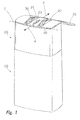
- Fig. 1 shows a discharge device according to the invention in an overall view.
- This discharge device has a medium reservoir 10, to which an assembly 20 is coupled, which in the manner explained below comprises the components which are required for discharging the medium from the medium reservoir 10.
- the assembly 20 has a housing, on whose front side an outlet opening 23 is provided for the medium.
- rolling members 30 are provided in openings 21 of the housing, which are mounted rotatably about a common axis of rotation 1 on the housing.
- a pump device within the housing is operatively coupled to the roll-off members 30 such that rotation of the roll-off members 30 about the roll-off member rotation axis 1 causes discharge of the medium through the outlet opening 23, regardless of the orientation of the discharge device.
- a closure flap 22 is provided, which is attached by means of a film hinge on the housing.
- the illustrated dispensing device is provided for applying media to the skin of a user. It may be both cosmetic and pharmaceutical media.
- the discharge device is pressed with its open end flap on the skin of the user with open flap 22 and then moved in one of the illustrated by the arrows 2 directions, in which case unwind the rolling members 30 on the skin of the user and thereby cause the discharge process.
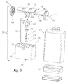
- Fig. 2 shows the assembly 20 and the media storage 10 in an exploded view.
- the housing of the assembly 20 comprises two housing components 24, 26, which are firmly connected to each other by means of connecting means 25. Together, the housing components 24, 26 define a receiving space 27 in which the components described below are arranged.
- These arranged in the receiving space 27 components initially include the previously mentioned Abrollglieder 30, which are mounted by means of a shaft member 32 and a receiving bore 26a for the axle 32 on the upper housing member 26 so that they through the openings 21 in the housing part 26 therethrough for the intended use according to protrude outside.
- components 41, 42, 43, 45, 46 of a pump device 40 are included, the pump cylinder of which is formed by a cylinder section 47 attached to the housing component 24.
- the components 41, 42, 43 form the piston of the pump device 40.
- the components 45, 46 and the cylinder portion 47 form the piston cylinder together with inlet valve.
- the medium reservoir 10 is formed in two parts and has a tow piston 12 used.
- the medium reservoir 10 is shown in dashed lines. It can be seen that this includes the drag piston 12, which is displaced in the direction of arrow 3 upwards.
- the region 14 above the drag piston 12 is filled with the medium to be discharged. In the course of the suction of the medium by the pumping device 40, the amount of media in the region 14 is reduced, so that due to the tightness of this region against incoming air of the tow piston 12 in the direction of the arrow 3 moves upward.
- the component 41 is hollow-cylindrical and has at its lower and at its upper end support portions 41 b, 41 c, which are displaceable in hollow cylindrical regions of the housing components 24, 26 along the pumping direction 4.
- the formed as a piston core member 42 is inserted and latched from below, wherein the locking portion 42a is formed in a manner not shown so that despite the inserted piston core 42 medium can flow into the hollow cylindrical member 41.
- piston sleeve 43 On the piston core 42 made of an elastic material piston sleeve 43 is pushed, which is compared to the composite of the piston core 42 and the component 41 slidably limited to form an exhaust valve on the outside is the piston sleeve 43 sealingly against the inner wall of the cylinder portion 47 and defines a cylindrical pumping chamber 44 upwards.
- a homogenization chamber 49 is bounded by the upper end 41 b and the outlet opening 23. The purpose of this homogenization chamber is described below with reference to Fig. 5a to 5d still explained.
- the lower end of the pumping device 40 is formed by an inlet opening 48, which is closed during a discharge operation of the valve ball 45, which is pressed by an elastically deflectable arm of the pressed-in the lower end of the cylinder portion 47 member 46 in its closed position.
- the Fig. 5a shows an initial state in which the piston 41, 42, 43 is in its upper end position, since the projections 41 a engage at this time in the part of the guide track 30 a, which is the Abrollglied axis of rotation 1 closest.
- the pumping chamber 44 is already filled with medium at this time, continued movement of the unwinding member 30 in the direction of Clockwise, indicated by arrow 5, to the fact that the piston 41, 42, 43 is pressed in the direction of arrow 4a down. Due to the depressed in the valve seat valve ball 45, the medium from the pumping chamber 44 can not escape down.
- the application of pharmaceutical or cosmetic liquids on the skin of a user is very easy, since the user must carry the discharge only under slight contact pressure on the skin. This causes a pumping operation of the pumping device 40. Since the medium reservoir 10 is formed with a drag piston 12 and thus always medium is present at the inlet 48 of the pumping device 40, it is also not to be feared that only air is sucked in by the pumping device 40. It therefore does not depend on the correct orientation of the discharge when the medium.
- Fig. 6a and 6b show an alternative design.
- a conventional discharge device 150 is used, which is supplemented by an attachment 120 according to the invention.
- the conventional discharge device 150 has a medium reservoir 152. Furthermore, it comprises an internal and not shown pumping device. It has an actuating portion 154 with an outlet tube 156. The pumping device, not shown, can be actuated by this actuating portion 154 is pressed together with the outlet tube 156 in the direction of the arrow 4a down.
- the attachment 120 with two housing parts 124, 126 is snapped into a corresponding groove 158 of the discharge device 150 by means of a snap-action device 124a.
- the coupled state is in the Fig. 6b shown.
- an actuating portion 141 of the attachment 120 designed as a hollow body rests on the actuating region 154 of the discharge device 150 and in this case comprises its outlet tube 156.
- the operating portion 141 is formed similar to the piston member 41 of the embodiment of Fig. 1 to 5 , In the same way as described there, it has extensions 141a, which engage in a guide groove 130a of two rolling members 130 of the attachment 120. A rolling of the rolling members 130 about the Abrollglied axis of rotation 1 thus results in the article 120 of the embodiment of Fig. 6a and 6b to a translational vertical displacement of the component 141, wherein thereby in the coupled state of the actuating portion 154 and the outlet tube 156 of the discharge 150 in a lifting movement be offset in the direction of arrow 4, which leads to a discharge process.
- the medium discharged thereby through the outlet pipe 156 penetrates at the lower end 141 b into the hollow cylindrical member 142 and leaves it at its upper end 141 c, to be subsequently discharged via the outlet opening 123.
- Fig. 7 shows an assembly 220, the alternative to the assembly 20 of the Fig. 1 to 5 Can be used. These are distinguished by the fact that instead of the piston pump device 40, a hose pumping device 240 is used.
- This peristaltic pumping device 240 has a pumping wheel 241, around which a pump hose 244 is connected, which connects an inlet 248 of the peristaltic pumping device 240 to an outlet opening 223. On the side facing away from the pump wheel 241, the pump hose 244 bears against a circular support surface 245.
- the pumping wheel 241 has axially on both sides two rolling members 230, which are rotatably connected to the pumping wheel 241.
- This design of the conveyor assembly 220 with a hose pump 240 allows a particularly simple and inexpensive construction of a discharge device according to the invention and an attachment according to the invention.
Landscapes
- Health & Medical Sciences (AREA)
- Engineering & Computer Science (AREA)
- Life Sciences & Earth Sciences (AREA)
- Animal Behavior & Ethology (AREA)
- Epidemiology (AREA)
- Pain & Pain Management (AREA)
- Physical Education & Sports Medicine (AREA)
- Rehabilitation Therapy (AREA)
- Mechanical Engineering (AREA)
- General Engineering & Computer Science (AREA)
- General Health & Medical Sciences (AREA)
- Public Health (AREA)
- Veterinary Medicine (AREA)
- Reciprocating Pumps (AREA)
- Massaging Devices (AREA)
- Containers And Packaging Bodies Having A Special Means To Remove Contents (AREA)
Abstract
Austragvorrichtung. Die Erfindung betrifft eine Austragvorrichtung für ein Medium mit einem Gehäuse, mit einer Auslassöffnung (23) für das Medium und mit einer Pumpvorrichtung zur Förderung des Mediums von einem Mediumspeicher (10) zu der Auslassöffnung (23), wobei die Pumpeinrichtung mindestens ein bewegliches erstes Pumpenglied aufweist, das durch eine Relativbewegung relativ zum Gehäuse eine Förderung vom Mediumspeicher (10) zur Auslassöffnung (23) bewirkt. Erfindungsgemäß ist mindestens ein um eine Abrollglied-Drehachse (1) drehbar am Gehäuse gelagertes Abrollglied (30) vorgesehen, welches zumindest zum Teil frei zugänglich an einer Außenseite des Gehäuses angeordnet ist und über einen Kopplungsmechanismus derart mit der Pumpvorrichtung gekoppelt ist, dass eine Drehbewegung des Abrollgliedes (30) eine Bewegung des ersten Pumpengliedes und dadurch eine Mediumförderung mittels der Pumpvorrichtung bewirkt. Verwendung insbesondere zum Austrag von kosmetischen oder pharmazeutischen Flüssigkeiten auf der Haut.Discharge. The invention relates to a discharge device for a medium with a housing, with an outlet opening (23) for the medium and with a pump device for conveying the medium from a medium reservoir (10) to the outlet opening (23), wherein the pump device has at least one movable first pump member which causes a conveyance from the medium reservoir (10) to the outlet opening (23) by means of a relative movement relative to the housing. According to the invention, at least one rolling member (30) rotatably mounted on the housing about a rolling member axis of rotation (1) is provided, which is at least partially freely accessible on an outside of the housing and is coupled to the pump device via a coupling mechanism such that a rotary movement of the Roll member (30) causes a movement of the first pump member and thereby a medium delivery by means of the pump device. Use especially for the discharge of cosmetic or pharmaceutical liquids on the skin.
Description
Die Erfindung betrifft eine Austragvorrichtung für ein Medium mit einem Gehäuse, einer Auslassöffnung für das Medium und einer Pumpvorrichtung zur Förderung des Mediums von einem Mediumspeicher zu der Auslassöffnung, wobei die Pumpeinrichtung mindestens ein bewegliches erstes Pumpenglied aufweist, das durch eine Relativbewegung relativ zum Gehäuse eine Förderung des Mediums vom Mediumspeicher zur Auslassöffnung bewirkt.The invention relates to a discharge device for a medium having a housing, an outlet opening for the medium and a pumping device for conveying the medium from a medium reservoir to the outlet opening, wherein the pumping device has at least one movable first pump member which promotes relative movement relative to the housing causes the medium from the medium reservoir to the outlet opening.
Gattungsgemäße Austragvorrichtungen sind aus dem Stand der Technik hinlänglich bekannt. Sie werden insbesondere zum Austrag von pharmazeutischen und kosmetischen Flüssigkeiten verwendet. Diese werden dabei üblicherweise durch Betätigen einer Betätigungshandhabe der Austragvorrichtung von einem Benutzer unter Verwendung der Pumpvorrichtung gefördert.Generic discharge devices are well known from the prior art. They are used in particular for the discharge of pharmaceutical and cosmetic liquids. These are usually conveyed by operating an actuating handle of the discharge by a user using the pumping device.
Ebenfalls sind aus dem Stand der Technik so genannte Deo-Roller bekannt, an deren Auslassseite eine Kugel gelagert ist, die durch Abrollen auf der Haut eines Benutzers gedreht wird. Dabei trägt sie einen Flüssigkeitsfilm von einem Innenraum des Deorollers nach außen, wo dieser durch Abrollen auf der Haut des Benutzers abgegeben wird.Also known from the prior art so-called deodorant scooters, on whose outlet side a ball is mounted, which is rotated by rolling on the skin of a user. She wears a liquid film from an interior of the deodorant roller to the outside, where it is discharged by rolling on the skin of the user.
Bei vielen Austragvorrichtungen des Standes der Technik liegt ein Problem darin, dass diese nur in bestimmten Ausrichtungen einen zuverlässigen Mediumsaustrag gewährleisten.One problem with many dispensing devices of the prior art is that they ensure reliable media discharge only in certain orientations.
Aufgabe der Erfindung ist es, eine gattungsgemäße Austragvorrichtung dahingehend weiterzubilden, dass diese eine besonders komfortable und zuverlässige Möglichkeit des Austrags eines Mediums auf einer Fläche, insbesondere auf einer Hautpartie eines Benutzers, gestattet.The object of the invention is to develop a generic discharge device to the effect that this allows a particularly comfortable and reliable way of discharging a medium on a surface, in particular on a skin area of a user.
Erfindungsgemäß wird dies dadurch erreicht, dass am Gehäuse einer erfindungsgemäßen Austragvorrichtung mindestens ein um eine Abrollglied-Drehachse drehbar gelagertes Abrollglied vorgesehen ist, welches zumindest zum Teil frei zugänglich an einer Außenseite des Gehäuses angeordnet ist und welches über einen Kopplungsmechanismus derart mit der Pumpvorrichtung gekoppelt ist, dass eine Drehbewegung des Abrollgliedes eine Bewegung des ersten Pumpengliedes und dadurch eine Mediumförderung mittels der Pumpvorrichtung bewirkt.According to the invention, this is achieved by providing at least one roll-off member rotatably mounted about a roll-off axis of rotation on the housing of a discharge device which is at least partially freely accessible on an outer side of the housing and which is coupled to the pumping device via a coupling mechanism. a rotational movement of the unrolling element causes a movement of the first pumping member and thereby a medium delivery by means of the pumping device.
Eine gattungsgemäße Austragvorrichtung ist vorzugsweise als mit einer Hand zu führende mobile Vorrichtung ausgebildet. Diese wird bestimmungsgemäß mit dem mindestens einen Abrollglied gegen eine mit dem Medium zu versehende Oberfläche, insbesondere einer Hautpartie, gedrückt. Ausgehend von dieser angedrückten Ausgangsstellung wird die Austragvorrichtung unter Aufrechterhaltung einer ausreichenden Andrückkraft quer zur Erstreckung der Abrollglieddrehachse auf der genannten Oberfläche bzw. Hautpartie bewegt, wobei es zum Abrollen des Abrollgliedes auf der Oberfläche kommt. Hierdurch wird die Pumpvorrichtung betätigt, die das Medium aus dem Mediumspeicher zur Auslassöffnung fördert, so dass dieses Medium dann auf der genannten Oberfläche abgegeben wird. Die erfindungsgemäße Austragvorrichtung ist insbesondere für ältere Menschen und für Menschen mit körperlichen Einschränkungen von Vorteil, da sie es gestattet, an beliebigen Körperpartien und ohne Einschränkung bezüglich der Ausrichtung der Austragvorrichtung das Medium auszubringen.A generic discharge device is preferably designed as a mobile device to be guided with one hand. This is intended with the at least one rolling member against a medium to be provided with the surface, in particular a skin area pressed. Starting from this pressed starting position, the discharge device is moved while maintaining a sufficient pressing force transversely to the extension of the Abrollglieddrehachse on said surface or skin area, wherein it comes to unroll the Abrollgliedes on the surface. This will cause the pumping device operated, which promotes the medium from the medium reservoir to the outlet opening, so that this medium is then discharged on said surface. The dispensing device according to the invention is particularly advantageous for the elderly and for people with physical disabilities, as it allows the medium to be deployed on any part of the body and without restriction as to the orientation of the dispensing device.
Die Auslassöffnung ist vorzugsweise gegenüber dem maximalen Radius des Abrollgliedes geringfügig zurückgesetzt, vorzugsweise um 2 mm oder weniger, insbesondere zwischen 1 mm und 2 mm. So ist gewährleistet, dass auch in einer Überkopflage das Medium die mit Medium zu versehende Fläche erreicht. Dieser Abstand von 1 mm bis 2 mm ist insbesondere im Zusammenhang mit einer breiten Auslassöffnung, vorzugsweise mit einer Breite von mindestens 15mm, von Vorteil, da sie es erlaubt, einen Streifen einer definierten Dicke und einer definierten Breite auf der Haut aufzubringen, der keine nachfolgende manuelle Verteilung durch den Benutzer mehr erfordert. Sehr zweckmäßig ist dies beispielsweise bei der Aufbringung von Kaltwachs.The outlet opening is preferably slightly set back from the maximum radius of the unwinding member, preferably by 2 mm or less, in particular between 1 mm and 2 mm. This ensures that even in an overhead position the medium reaches the area to be provided with the medium. This distance of 1 mm to 2 mm is particularly advantageous in connection with a wide outlet opening, preferably with a width of at least 15 mm, since it allows a strip of a defined thickness and a defined width to be applied to the skin, not a subsequent one Manual distribution by the user requires more. This is very useful, for example, in the application of cold wax.
Das Abrollglied ist vorzugsweise als Rad ausgebildet. Es kann jedoch auch als um die Abrollglied-Drehachse drehbare Kugel gestaltet sein. Die Abrollglied-Drehachse ist vorzugsweise orthogonal zur Haupterstreckungsrichtung der Austragvorrichtung und/oder zur durch die Auslassöffnung definierten Austragrichtung ausgerichtet.The rolling member is preferably formed as a wheel. However, it can also be designed as a rotatable about the Abrollglied rotation axis ball. The Abrollglied-axis of rotation is preferably aligned orthogonal to the main direction of extension of the discharge and / or defined by the discharge opening discharge.
Das Abrollglied kann selbst in der Auslassöffnung angeordnet sein, so dass das Medium über das Abrollglied abgegeben wird. Bevorzugt ist jedoch eine Gestaltung, bei der die Auslassöffnung vom Abrollglied getrennt ausgebildet ist und bei der insbesondere unterschiedliche Durchbrechungen in einer Gehäusewandung für das Abrollglied einerseits und die Auslassöffnung andererseits vorgesehen sind. Die Auslassöffnung kann verschiedene Formen aufweisen und so beispielsweise dafür ausgebildet sein, das Medium in Form eines breiten Strichs abzugeben.The unwinding member may itself be arranged in the outlet opening, so that the medium is dispensed via the unrolling member. However, a design is preferred in which the outlet opening is formed separately from the unrolling element and in which, in particular, different perforations are provided in a housing wall for the unrolling member on the one hand and the outlet opening on the other hand. The outlet opening may have various shapes and thus be designed, for example, to deliver the medium in the form of a broad stroke.
Als Mediumspeicher kommen die für Austragvorrichtungen bekannten üblichen Gestaltungen in Frage. So kann ein Mediumspeicher so gestaltet sein, dass er ein konstantes Volumen aufweist, wobei im Zuge des Austrags des Mediums zur Verhinderung eines Unterdrucks im Mediumspeicher Luft angesaugt wird, um das ausgetragene Medium im Mediumspeicher zu ersetzen. Bevorzugt wird jedoch ein volumenveränderlicher Mediumspeicher, insbesondere ein Mediumspeicher wie eine Tube oder ein Beutel mit einer formflexiblen Wandung, die sich dem verringernden Medienvolumen anpasst, oder ein Mediumspeicher mit einem Schleppkolben. Solche Gestaltungen mit volumenveränderlichen Mediumspeichern sind von Vorteil, da sie über ihren vollständigen Lebenszyklus keine Luft aufnehmen und somit keine Gefahr besteht, dass die Pumpvorrichtung statt des Mediums bei ungünstiger Ausrichtung der Austragvorrichtung Luft ansaugt.As a medium storage known for discharge devices usual designs come into question. Thus, a medium storage can be designed so that it has a constant volume, wherein in the course of the discharge of the medium to prevent a negative pressure in the medium storage air is sucked to replace the discharged medium in the medium storage. However, preference is given to a volume-variable medium reservoir, in particular a medium reservoir such as a tube or a bag with a shape-flexible wall which adapts to the decreasing volume of media, or a medium reservoir with a drag piston. Such designs with volume-variable medium reservoirs are advantageous because they do not absorb air over their entire life cycle and thus there is no danger that the pumping device sucks air instead of the medium in unfavorable orientation of the discharge.
Die Pumpvorrichtung ist derart ausgebildet, dass sie das Medium aus dem Mediumspeicher per Unterdruck ansaugt oder das Medium im Mediumspeicher unter Überdruck setzt, so dass ein Mediumaustrag zuverlässig und unabhängig von der Ausrichtung der Austragvorrichtung gewährleistet ist. Die Pumpvorrichtung kann derart ausgebildet sein, dass sie den Mediumspeicher unmittelbar umfasst. Bei einer solchen Ausgestaltung wird der Mediumspeicher somit hinsichtlich seines Volumens im Zuge des Abrollens des Abrollgliedes verringert, um das Medium zur Auslassöffnung zu fördern. Bevorzugt ist allerdings eine Gestaltung, bei der die Pumpvorrichtung separat ausgebildet ist und zwischen dem Mediumspeicher einerseits und der Auslassöffnung andererseits angeordnet ist.The pump device is designed such that it sucks the medium from the medium reservoir by means of negative pressure or sets the medium in the medium reservoir under overpressure, so that a medium discharge is ensured reliably and independently of the orientation of the discharge. The pumping device may be designed such that it directly encompasses the medium reservoir. In such an embodiment, the medium reservoir is thus reduced in volume in the course of rolling the Abrollgliedes to promote the medium to the outlet. However, a design is preferred in which the pump device is designed separately and is arranged between the medium reservoir on the one hand and the outlet opening on the other hand.
Die Pumpvorrichtung weist mit dem ersten Pumpenglied zumindest ein Pumpenglied auf, welches beweglich gegenüber dem Gehäuse ausgebildet ist. Vorzugsweise begrenzt dieses bewegliche Pumpenglied unmittelbar eine volumenveränderliche Pumpkammer der Pumpvorrichtung. Alternativ fördert es das Medium mittelbar, wobei es hierfür beispielsweise als Gleitschuh einer Schlauchpumpe ausgebildet sein kann.The pump device has, with the first pump member, at least one pump member, which is designed to be movable relative to the housing. Preferably, this movable pump member directly limits a volume variable pumping chamber of the pumping device. Alternatively, it indirectly conveys the medium, it being possible for example to design it as a sliding shoe of a peristaltic pump.
Bei einer ersten Ausgestaltung ist das erste Pumpenglied drehbeweglich gegenüber dem Gehäuse gelagert. Dies erlaubt eine vergleichsweise einfache Ausgestaltung des Kopplungsmechanismus. Besonders einfach ist die Gestaltung, wenn das Pumpenglied koaxial zu dem mindestens einen Abrollglied ausgebildet ist und mit diesem fest verbunden ist. Eine größere bauliche Flexibilität wird erreicht, wenn das drehbare erste Pumpenglied um eine von der Abrollglied-Drehachse abweichende Achse drehbeweglich gelagert ist, wobei diese beispielsweise parallel zur Abrollglied-Drehachse angeordnet sein kann.In a first embodiment, the first pump member is rotatably mounted relative to the housing. This allows a comparatively simple embodiment of the coupling mechanism. Particularly simple is the design, when the pump member is formed coaxially with the at least one Abrollglied and is firmly connected thereto. A greater structural flexibility is achieved when the rotatable first pump member is rotatably mounted about an axis deviating from the Abrollglied axis of rotation, which may for example be arranged parallel to the Abrollglied axis of rotation.
Ein solches drehbar gelagertes erstes Pumpenglied kann beispielsweise als Förderschnecke ausgebildet sein oder insbesondere als Teil einer Schlauchpumpe, deren Förderschlauch mittels des ersten Pumpengliedes zusammengequetscht wird, um das im Schlauch befindliche Medium in Richtung der Auslassöffnung zu drücken.Such a rotatably mounted first pump member may be formed, for example, as a screw conveyor or in particular as part of a peristaltic pump whose delivery hose is squeezed together by means of the first pump member to push the medium in the hose in the direction of the outlet opening.
Alternativ zu einem drehbar gegenüber dem Gehäuse gelagerten ersten Pumpenglied kann das erste Pumpenglied insbesondere auch translativ beweglich gegenüber dem Gehäuse und/oder gegenüber einem zweiten Pumpenglied der Pumpvorrichtung ausgebildet sein. Dies erlaubt die Gestaltung der Pumpvorrichtung als Kolbenpumpe, wobei das erste Pumpenglied in einem solchen Fall vorzugsweise fest mit dem Kolben dieser Kolbenpumpe verbunden ist oder diesen bildet. Auch eine Ausgestaltung der Pumpvorrichtung als Balgpumpe ist durch ein translativ bewegliches erstes Pumpenglied realisierbar.As an alternative to a first pump member rotatably mounted relative to the housing, the first pump member may in particular also be designed to be translationally movable relative to the housing and / or to a second pump member of the pump apparatus. This allows the design of the pump device as a piston pump, wherein the first pump member in such a case is preferably fixedly connected to the piston of this piston pump or forms. An embodiment of the pumping device as a bellows pump can also be realized by a first pumping element that is movable in translation.
Eine Variante dessen sieht vor, die Pumpvorrichtung mit dem ersten und dem zweiten Pumpenglied gemeinsam als Ganzes um eine erste Schwenkachse schwenkbeweglich am Gehäuse zu lagern, wobei das erste Pumpenglied um eine abrollgliedseitig ortsfeste und exzentrisch zur Abrollglied-Drehachse angeordnete Schwenkachse schwenkbeweglich am Abrollglied gelagert ist. Bei einer solchen Gestaltung wird somit die vorzugsweise als Kolbenpumpe ausgebildete Pumpvorrichtung in ihrer Gesamtheit im Gehäuse schwenkbar gelagert. Das erste Pumpglied und das zweite Pumpglied bilden dabei den Zylinder und den Kolben der Pumpvorrichtung. Durch die schwenkbegliche Anbindung des ersten Pumpgliedes exzentrisch am Abrollglied wird dann während des Abrollens des Abrollgliedes gleichzeitig eine Pendelbewegung der Pumpvorrichtung in ihrer Gesamtheit und eine Hubbewegung des ersten Pumpgliedes gegenüber dem zweiten Pumpglied bewirkt.A variant of this provides, the pump device with the first and the second pump member together as a whole about a first pivot axis pivotally mounted on the housing, wherein the first pump member is mounted on a abrollgliedseitig stationary and eccentric to the Abrollglied axis of rotation pivot axis pivotally mounted on the rolling member. With such a configuration, the pump device, which is preferably designed as a piston pump, is thus pivotally mounted in its entirety in the housing. The first pumping member and the second pumping member form the cylinder and the piston of the pumping device. Due to the pivotable connection of the first pumping member eccentrically on the rolling member is then simultaneously effected during the rolling of the Abrollgliedes a pendulum movement of the pumping device in its entirety and a lifting movement of the first pumping member relative to the second pumping member.
Von Vorteil ist jedoch eine Variante, bei der das erste Pumpglied entlang eines gehäusefesten Bewegungspfades gegenüber dem Gehäuse translativ beweglich geführt ist.However, a variant in which the first pumping member is guided in a translationally movable manner along a housing-fixed movement path relative to the housing is advantageous.
Die Kopplungsmechanik zwischen dem Abrollglied und dem ersten Pumpglied kann in einem solchen Falle beispielsweise über einen schwenkbar am ersten Pumpglied und schwenkbar exzentrisch am Abrollglied angebrachtes Pleuel-Zwischenglied erzielt werden. Von Vorteil ist jedoch eine Gestaltung, bei der mittels einer Kulissenführung das erste Pumpglied mit dem Abrollglied wirkverbunden ist, wobei diese Kulissenführung vorzugsweise eine um eine Führungsspur-Drehachse drehbare und diese Führungsspur-Drehachse umgebende Führungsspur am Abrollglied oder einem mit dem Abrollglied wirkverbundenen Drehglied umfasst, die von der Führungsspur-Drehachse variierend beabstandet ist, und wobei die Kulissenführung weiterhin einen Fortsatz umfasst, der am ersten Pumpenglied angebracht ist und der in die Führungsspur eingreift.The coupling mechanism between the unwinding member and the first pumping member can be achieved in such a case, for example via a pivotally mounted on the first pumping member and pivotally eccentrically mounted on the unwinding connecting rod intermediate member. However, a design is advantageous in which the first pumping member is operatively connected to the unwinding member by means of a slotted guide, this slotted guide preferably comprising a guide track rotatable about a guide track rotation axis and surrounding this guide track rotation axis on the unrolling member or a rotary member operatively connected to the unrolling member, which is spaced from the guide track rotation axis varying, and wherein the slotted guide further comprises an extension, the is attached to the first pump member and engages in the guide track.
Hierdurch ist ein vergleichsweise einfacher Aufbau mit wenigen Bauteilen möglich. Insbesondere einfach kann dieser Aufbau gestaltet sein, wenn die Führungsspur der Kulissenführung unmittelbar am Abrollglied vorgesehen ist, so dass die Führungsspur gemeinsam mit dem Abrollglied um die Abrollglied-Drehachse dreht. Der Fortsatz, der am Pumpenglied angebracht ist und daher gegenüber dem Gehäuse nur linear beweglich ist, wird durch die variierende Beabstandung der Führungsspur von der Führungsspurdrehachse translativ verlagert und bewirkt somit den Pumpvorgang der Pumpvorrichtung.As a result, a comparatively simple construction with few components is possible. In particular, this structure can be designed simply, if the guide track of the slide guide is provided directly on the rolling member, so that the guide track rotates together with the rolling member to the Abrollglied rotation axis. The extension, which is attached to the pump member and therefore only linearly movable relative to the housing, is translationally displaced by the varying spacing of the guide track of the guide track rotation axis and thus causes the pumping operation of the pumping device.
Eine Kopplungsmechanik mit Kulissenführung erzwingt sowohl die Hubals auch die Rückhubbewegung des ersten Pumpengliedes, so dass auch eine Rückstellfeder, insbesondere auf eine metallische Rückstellfeder, verzichtet werden kann.A coupling mechanism with slide guide forces both the Hubals and the return stroke of the first pump member, so that a return spring, in particular a metallic return spring, can be omitted.
Die von der Führungsspurdrehachse variierend beanstandete Führungsspur kann im einfachsten Falle eine zur Führungsspur exzentrische Kreisform aufweisen. Von Vorteil können auch komplexere Gestaltungen sein, bei denen der Abstand der Führungsspur von der Führungsspurdrehachse eine Mehrzahl von Minima und Maxima aufweist, insbesondere je zwei oder je drei Minima und Maxima aufweist, da hierdurch bewirkt werden kann, dass eine 360°-Drehbewegung der Führungsspur zwei, drei oder auch mehr Pumpenhübe einer Kolbenpumpe bewirkt.In the simplest case, the guide track, which is subject to varying degrees of deviation from the guide track rotational axis, can have an eccentric circular shape with respect to the guide track. Advantageous may also be more complex designs, in which the distance of the guide track from the guide track rotational axis has a plurality of minima and maxima, in particular two or three minima and maxima, since this can cause a 360 ° rotational movement of the guide track two, three or more pump strokes causes a piston pump.
Da je nach Art der verwendeten Pumpvorrichtung eine kontinuierliche Förderung des Mediums nicht möglich ist, beispielsweise wegen des bei einer Kolbenpumpe erforderlichen Rückhubs, kann es vorteilhaft sein, mindestens zwei Pumpvorrichtungen vorzusehen, wobei das mindestens eine Abrollglied über den Kopplungsmechanismus derart mit den beiden Pumpvorrichtungen gekoppelt ist, das eine Drehbewegung des Abrollgliedes zeitlich gegeneinander versetzte Mediumförderungen durch die Pumpvorrichtung bewirkt. Auch ist es möglich, der Pumpkammer der Pumpvorrichtung eine Homogenisierungskammer nachzuschalten, die während des Pumphubs der Pumpvorrichtung einen Teil des Mediums, vorzugsweise 50% dessen, aufnimmt und die während des Rückhubs dieses gespeicherte Medium durch die Auslassöffnung abgibt. Auch so ist eine quasi-kontinuierliche Förderung des Mediums erreichbar.Since, depending on the type of pumping device used, a continuous delivery of the medium is not possible, for example because of the return stroke required for a piston pump, it may be advantageous to provide at least two pumping devices, wherein the at least a Abrollglied is coupled via the coupling mechanism in such a way with the two pumping devices, which causes a rotational movement of the Abrollgliedes temporally staggered medium promotions through the pumping device. It is also possible for the pumping chamber of the pumping device to be followed by a homogenisation chamber which receives part of the medium, preferably 50%, of it during the pumping stroke of the pumping device and which discharges this stored medium through the outlet opening during the return stroke. Even so, a quasi-continuous promotion of the medium can be achieved.
Die Erfindung betrifft weiterhin auch einen Aufsatz zur Verwendung mit einer Austragvorrichtung. Die Austragvorrichtung, zu deren Verwendung ein solcher Aufsatz vorgesehen ist, umfasst ein Gehäuse, einen Mediumspeicher, eine Auslassöffnung, eine Pumpvorrichtung zur Förderung von Medium aus dem Mediumspeicher zur Auslassöffnung und einen translativ gegenüber dem Gehäuse beweglichen Betätigungsbereich, durch dessen translative Verlagerung die Pumpvorrichtung betätigt werden kann.The invention also relates to an attachment for use with a discharge device. The discharge device, for the use of which such an attachment is provided, comprises a housing, a medium reservoir, an outlet opening, a pumping device for conveying medium from the medium reservoir to the outlet opening and an actuating region movable in translation relative to the housing, by means of which the pumping device is actuated by translational displacement can.
Der Aufsatz ist erfindungsgemäß derart ausgebildet, dass er ein Gehäuse aufweist, welches zur lösbaren Ankopplung am Gehäuse der Austragvorrichtung ausgebildet ist. Weiterhin weist der Aufsatz ebenso wie die oben beschriebene erfindungsgemäße Austragvorrichtung ein um eine Drehachse drehbar am Gehäuse des Aufsatzes gelagertes Abrollglied auf, welches zumindest zum Teil frei zugänglich an einer Außenseite des Gehäuses des Aufsatzes angeordnet ist. Der Aufsatz verfügt weiterhin über ein translativ geführt gegenüber dem Gehäuse des Aufsatzes beweglichen Betätigungsabschnitt, der dafür ausgebildet ist, in einem Kopplungszustand, in dem der Aufsatz an der Austragvorrichtung angekoppelt ist, an der Betätigungsfläche der Austragvorrichtung anzuliegen. Darüber hinaus ist ein Kopplungsmechanismus vorgesehen, der derart mit dem Betätigungsabschnitt und dem Abrollglied gekoppelt ist, das eine Drehbewegung des Abrollgliedes eine translative Hubbewegung des Betätigungsabschnittes bewirkt.The attachment according to the invention is designed such that it has a housing which is designed for releasable coupling to the housing of the discharge device. Furthermore, the article as well as the discharge device according to the invention described above, a rotatably mounted about an axis of rotation on the housing of the essay mounted rolling member, which is arranged at least partially freely accessible on an outer side of the housing of the essay. The attachment further has a translationally guided relative to the housing of the attachment movable actuating portion which is adapted to abut in a coupling state in which the attachment is coupled to the discharge device, on the actuating surface of the discharge device. In addition, a coupling mechanism is provided, the is coupled to the actuating portion and the rolling member, which causes a rotational movement of the rolling member a translational lifting movement of the actuating portion.
Ein erfindungsgemäßer Aufsatz funktioniert ähnlich der vorgeschriebenen erfindungsgemäßen Austragvorrichtung. Allerdings verfügt der Aufsatz anders als die erfindungsgemäße Austragvorrichtung nicht selbst über eine Pumpvorrichtung und einen Mediumspeicher, sondern ist stattdessen dafür ausgebildet, auf eine an sich bekannte Austragvorrichtung aufgesetzt zu werden, die diese Komponenten enthält. Der Kopplungsmechanismus ist daher nicht dafür ausgebildet, unmittelbar das Abrollglied mit einem Teil der Pumpvorrichtung zu verbinden, sondern wirkt auf den Betätigungsabschnitt, der seinerseits die Pumpvorrichtung der angekoppelten Austragvorrichtung bewegt und zu diesem Zwecke beispielsweise auf einer zur manuellen Betätigung vorgesehen Betätigungshandhabe der Austragvorrichtung aufliegt.An inventive attachment works similar to the prescribed discharge device according to the invention. However, unlike the discharge device according to the invention, the attachment does not itself have a pumping device and a medium reservoir, but is instead designed to be placed on a discharge device known per se, which contains these components. The coupling mechanism is therefore not adapted to directly connect the rolling member with a part of the pumping device, but acts on the actuating portion, which in turn moves the pumping device of the coupled discharge and rests for this purpose, for example on an operating handle provided for manual operation of the discharge.
Der erfindungsgemäße Aufsatz kann genutzt werden, um auf einfache Weise herkömmliche Austragvorrichtungen dahingehend zu modifizieren, dass diese in Reaktion auf das Abrollen des Abrollgliedes das ihnen gespeicherte Medium austragen. Die hierfür verwendeten Austragvorrichtungen können in einer unmittelbar zum manuellen Austrag geeigneten Form Verwendung finden. Es kann jedoch auch vorgesehen sein, dass ein an diesen Austragvorrichtungen angeordneter Applikator abgenommen wird, bevor der erfindungsgemäße Aufsatz ankoppelbar ist.The attachment according to the invention can be used to easily modify conventional dispensing devices to dispense the medium stored in response to the unwinding of the unwinding member. The discharge devices used for this purpose can be used in a form suitable directly for manual discharge. However, it can also be provided that an applicator arranged on these discharge devices is removed before the attachment according to the invention can be coupled.
Das Gehäuse des Aufsatzes kann am Gehäuse der Austragvorrichtung vorzugsweise mittels einer werkzeuglos erzielbaren Verbindung angebunden sein, beispielsweise durch eine Schnappverbindung.The housing of the attachment can preferably be attached to the housing of the discharge device by means of a connection that can be achieved without tools, for example by a snap connection.
Der Aufsatz kann bei einer ersten Ausgestaltung ohne eigene Auslassöffnung auskommen. In einem solchen Fall ist der Aufsatz so gestaltet, dass die Auslassöffnung der Austragvorrichtung, an die der Aufsatz bestimmungsgemäß angekoppelt wird, auch bei aufgesetztem Aufsatz derart freiliegt, dass das Medium direkt durch sie ausgetragen werden kann. Von Vorteil ist jedoch eine Gestaltung, bei der der Aufsatz einen Verbindungskanal aufweist, der eine am Aufsatz vorgesehene Auslassöffnung mit einer am Aufsatz vorgesehenen Einlassöffnung verbindet, wobei die Einlassöffnung derart am Aufsatz angeordnet ist, dass sie im Kopplungszustand mit der Auslassöffnung der Austragvorrichtung verbunden ist.The essay can make do without its own outlet opening in a first embodiment. In such a case, the essay is designed to in that the outlet opening of the discharge device to which the attachment is intended to be coupled is exposed even when the attachment is mounted in such a way that the medium can be discharged directly through it. However, a design in which the attachment has a connecting channel which connects an outlet opening provided on the attachment with an inlet opening provided on the attachment is advantageous, wherein the inlet opening is arranged on the attachment in such a way that it is connected in the coupling state to the outlet opening of the discharge device.
Eine solche Gestaltung kann von Vorteil sein, da der Aufsatz keine Aussparungen oder dergleichen braucht, um die Auslassöffnung der Austragvorrichtung zugänglich zu belassen. Hinzukommt, dass bei vielen Austragvorrichtungen, die zur Verwendung mit dem Aufsatz grundsätzlich geeignet sind, die Auslassöffnung gemeinsam mit der Betätigungshandhabe im Zuge eines Betätigungsvorgangs verlagert wird, so dass ohne eigene Auslassöffnung des Aufsatzes eine Verlagerung der Auslassöffnung der Austragvorrichtung gegenüber dem Aufsatz im Zuge der Betätigung zu erwarten wäre. Eine an dem Aufsatz vorgesehene Auslassöffnung gestattet es darüber hinaus, die Austragcharakteristik des Mediums durch der Auslassöffnung zugeordnete Strömungsgeometrien gezielt zu beeinflussen.Such a design may be advantageous because the attachment does not need recesses or the like to leave the discharge opening of the discharge device accessible. In addition, in many discharge devices, which are in principle suitable for use with the attachment, the outlet opening is displaced together with the actuating handle in the course of an actuation operation, so that without own outlet opening of the attachment a displacement of the outlet opening of the discharge relative to the attachment in the course of actuation would be expected. An outlet opening provided on the attachment also makes it possible to influence the discharge characteristics of the medium in a targeted manner through flow geometries assigned to the outlet opening.
Ähnlich der vorbeschriebenen erfindungsgemäßen Austragvorrichtung wird es als vorteilhaft angesehen, wenn der Kopplungsmechanismus, der das Abrollglied mit dem translativ beweglichen Betätigungsabschnitt koppelt, eine Kulissenführung aufweist. Diese verfügt vorzugsweise über um eine Führungsspur-Drehachse drehbare und die Führungsspur-Drehachse umgebende Führungsspur am Abrollglied selbst oder an einem mit diesem verbundenen Drehglied, wobei die Führungsspur von der Führungsspur-Drehachse variierend beabstandet ist. Weiterhin verfügt diese Kulissenführung über einen Fortsatz, der in diesem Falle am Betätigungsabschnitt angebracht ist und der in die Führungsspur eingreift.Similar to the above-described discharge device according to the invention, it is considered advantageous if the coupling mechanism, which couples the roll-off member with the translationally movable operating portion, has a slotted guide. This preferably has about a guide track rotation axis rotatable and the guide track axis of rotation surrounding guide track on the rolling member itself or on a connected thereto rotary member, wherein the guide track is spaced from the guide track rotation axis varying. Furthermore, this link guide has an extension, in this case on Operating section is mounted and engages in the guide track.
Die Funktionsweise entspricht dabei der oben erläuterten Funktionsweise in Hinblick auf die erfindungsgemäße Austragvorrichtung.The mode of operation corresponds to the above-described mode of operation with regard to the discharge device according to the invention.
Zur leichten Handhabung der erfindungsgemäßen Austragvorrichtung oder des erfindungsgemäßen Aufsatzes wird es als vorteilhaft angesehen, wenn zwei um eine identische Abrollglied-Drehachse drehbare Abrollglieder vorgesehen sind, wobei die Auslassöffnung der Austragvorrichtung bzw. des Aufsatzes zwischen den Abrollgliedern angeordnet ist. Die Verwendung zweier Abrollglieder führt zu einer erhöhten Stabilität und einer leichteren Handhabbarkeit während der Benutzung.For easy handling of the dispensing device according to the invention or the article according to the invention, it is considered advantageous if two rolling elements rotatable about an identical rolling element rotation axis are provided, wherein the outlet opening of the discharge device or the attachment is arranged between the rolling elements. The use of two unwinding leads to increased stability and easier handling during use.
Weiterhin wird es als vorteilhaft angesehen, wenn im Bereich der Auslassöffnung der Austragvorrichtung bzw. des Aufsatzes ein druckabhängig öffnendes Auslassventil vorgesehen ist, um das Eindringen von Verunreinigungen zu verhindern.Furthermore, it is considered advantageous if a pressure-dependent opening outlet valve is provided in the region of the outlet opening of the discharge device or of the attachment in order to prevent the penetration of contaminants.
Das mindestens eine Abrollglied ist vorzugsweise als Massagerolle mit einer Mehrzahl von in radialer Richtung herausragenden Fortsätzen ausgebildet. Mit einer solchen Massagerolle wird gleichzeitig mit dem Austrag von Medium auch eine entspannende Wirkung des behandelten Körperteils erzielt. Von Vorteil ist es weiterhin, wenn das mindestens eine Abrollglied werkzeuglos austauschbar ist, so dass die Massagewirkung durch einen Wechsel des Abrollgliedes gezielt hergestellt, angepasst und vermieden werden kann.The at least one unwinding member is preferably designed as a massage roller with a plurality of protruding projections in the radial direction. With such a massage roller, a relaxing effect of the treated body part is achieved simultaneously with the discharge of medium. It is also advantageous if the at least one unwinding element is exchangeable without tools, so that the massaging effect can be selectively produced, adapted and avoided by changing the unwinding element.
Die Erfindung umfasst neben der erfindungsgemäßen Austragvorrichtung und dem erfindungsgemäßen Aufsatz auch ein Set aus einem erfindungsgemäßen Aufsatz und einer an sich bekannten Austragvorrichtung mit den oben genannten Teilkomponenten. Dabei ist der Aufsatz derart an die Austragvorrichtung angepasst, dass das Gehäuse des Aufsatzes an das Gehäuse der Austragvorrichtung ankoppelbar ist. In dem dadurch erzielbaren gekoppelten Zustand liegt der Betätigungsabschnitt des Aufsatzes am Betätigungsbereich der Austragvorrichtung an.The invention comprises, in addition to the discharge device according to the invention and the attachment according to the invention also a set of an attachment according to the invention and a known discharge with the above sub-components. Here is the essay adapted to the discharge device, that the housing of the attachment to the housing of the discharge device can be coupled. In the coupled state that can be achieved thereby, the actuating portion of the attachment abuts against the actuating region of the discharge device.
Grundsätzlich ist eine erfindungsgemäße Austragvorrichtung bzw. ein Set mit einem erfindungsgemäßen Aufsatz für eine Vielzahl flüssiger Medien verwendbar. So ist beispielsweise eine Verwendung mit Lebensmitteln oder Klebstoff möglich. Als insbesondere bestimmungsgemäße Verwendung wird jedoch die Nutzung mit pharmazeutischen oder kosmetischen Produkten angesehen, die auf der Haut eines Patienten aufzubringen sind. Es wird demnach als bevorzugt angesehen, wenn die erfindungsgemäße Austragvorrichtung bzw. die Austragvorrichtung mit erfindungsgemäßem Aufsatz mit einer derartigen kosmetischen oder pharmazeutischen Flüssigkeit gefüllt ist. Als kosmetische Flüssigkeiten kommen insbesondere Pflegecreme, Cullulitecreme, Sonnencreme, Bodylotion, Duschgel, Selbstbräuner sowie Kaltwachsspender für die Enthaarung von Körperpartien in Betracht.In principle, a dispensing device according to the invention or a set with an attachment according to the invention can be used for a large number of liquid media. For example, use with food or glue is possible. However, use in particular with pharmaceutical or cosmetic products which are to be applied to the skin of a patient is regarded as intended use in particular. Accordingly, it is considered preferable if the discharge device according to the invention or the discharge device with the attachment according to the invention is filled with such a cosmetic or pharmaceutical liquid. As cosmetic fluids are especially nourishing cream, Cullulitecreme, sunscreen, body lotion, shower gel, self-tanner and cold wax dispenser for the depilation of body parts into consideration.
Weitere Aspekte und Vorteile der Erfindung ergeben sich außer aus den Ansprüchen auch aus der nachfolgenden Beschreibung zweier bevorzugter Ausführungsbeispiele der Erfindung, die nachfolgend anhand der Figuren erläutert werden. Dabei zeigen:
- Fig. 1
- eine erfindungsgemäße Austragvorrichtung in einer Gesamtansicht,
- Fig. 2
- eine Explosionsdarstellung der Austragvorrichtung der
Fig. 1 , - Fig. 3 und Fig. 4
- die Austragvorrichtung der
Fig. 1 in zwei geschnittenen Darstellungen, - Fig. 5a bis 5d
- die Pumpvorrichtung der Austragvorrichtung der
Fig. 1 in verschiedenen Stadien während des Pumpvorgangs , - Fig. 6a und 6b
- ein Set aus einer herkömmlichen Austragvorrichtung mit einem erfindungsgemäßen Aufsatz und
- Fig. 7
- eine zur Gestaltung gemäß der Ausführungsform der
Fig. 1 alternative Variante der Förderbaugruppebis 5
- Fig. 1
- a discharge device according to the invention in an overall view,
- Fig. 2
- an exploded view of the discharge of the
Fig. 1 . - FIG. 3 and FIG. 4
- the discharge of the
Fig. 1 in two cut representations, - Fig. 5a to 5d
- the pumping device of the discharge of the
Fig. 1 at various stages during the pumping process, - Fig. 6a and 6b
- a set of a conventional discharge device with an attachment according to the invention and
- Fig. 7
- a for designing according to the embodiment of the
Fig. 1 to 5 alternative variant of the conveyor assembly
Diese Austragvorrichtung verfügt über einen Mediumspeicher 10, an den eine Baugruppe 20 angekoppelt ist, die in nachfolgend noch erläuterter Weise die Komponenten umfasst, die zum Austragen des Mediums aus dem Mediumspeicher 10 erforderlich sind. Die Baugruppe 20 weist ein Gehäuse auf, an dessen Stirnseite eine Auslassöffnung 23 für das Medium vorgesehen ist. Beidseitig der Auslassöffnung 23 sind in Durchbrechungen 21 des Gehäuses Abrollglieder 30 vorgesehen, die um eine gemeinsame Drehachse 1 drehbar am Gehäuse gelagert sind. In nachfolgend noch erläuterter Weise ist eine Pumpvorrichtung innerhalb des Gehäuses mit den Abrollgliedern 30 derart wirkgekoppelt, dass ein Drehen der Abrollglieder 30 um die Abrollglied-Drehachse 1 ungeachtet der Ausrichtung der Austragvorrichtung einen Austrag des Mediums durch die Auslassöffnung 23 hindurch bewirkt. Zum Schutz der Austragöffnung 23 bei Nichtgebrauch ist eine Verschlussklappe 22 vorgesehen, der mittels eines Filmscharniers am Gehäuse angebracht ist.This discharge device has a
Die dargestellte Austragvorrichtung ist zum Applizieren von Medien auf der Haut eines Benutzers vorgesehen. Es kann sich dabei sowohl um kosmetische als auch um pharmazeutische Medien handeln. Zur Verwendung wird die Austragvorrichtung bei geöffneter Verschlussklappe 22 mit ihrer obenseitigen Stirnseite auf die Haut des Benutzers gedrückt und dann in eine der durch die Pfeile 2 verdeutlichten Richtungen bewegt, wobei hierbei die Abrollglieder 30 auf der Haut des Benutzers abrollen und dadurch den Austragvorgang bewirken.The illustrated dispensing device is provided for applying media to the skin of a user. It may be both cosmetic and pharmaceutical media. For use, the discharge device is pressed with its open end flap on the skin of the user with
Diese im Aufnahmeraum 27 angeordneten Komponenten umfassen zunächst die bereits genannten Abrollglieder 30, welche mittels eines Achselements 32 und einer Aufnahmebohrung 26a für das Achselement 32 am oberen Gehäusebauteil 26 gelagert sind, so dass sie durch die Durchbrechungen 21 im Gehäuseteil 26 hindurch für die bestimmungsgemäße Verwendung nach außen ragen.These arranged in the receiving
Weiterhin sind im Aufnahmeraum 27 Bauteile 41, 42, 43, 45, 46 einer Pumpeinrichtung 40 enthalten, deren Pumpenzylinder durch einen am Gehäusebauteil 24 angebrachten Zylinderabschnitt 47 gebildet wird. Die Bauteile 41, 42, 43 bilden den Kolben der Pumpvorrichtung 40. Die Bauteile 45, 46 sowie die Zylinderabschnitt 47 bilden den Kolbenzylinder mitsamt Einlassventil.Further, in the receiving
Der Mediumspeicher 10 ist zweiteilig ausgebildet und verfügt über einen eingesetzten Schleppkolben 12.The
In zusammengesetzter Form sind die Bauteile in den
In diesen Figuren ist der Mediumspeicher 10 gestrichelt dargestellt. Es ist zu erkennen, dass dieser den Schleppkolben 12 beinhaltet, welcher in Richtung des Pfeils 3 nach oben verschiebbar ist. Der Bereich 14 oberhalb des Schleppkolbens 12 ist mit dem auszutragenden Medium gefüllt. Im Zuge des Ansaugens des Mediums durch die Pumpvorrichtung 40 wird die Medienmenge im Bereich 14 verringert, so dass aufgrund der Dichtigkeit dieses Bereich gegen einströmende Luft der Schleppkolben 12 in Richtung des Pfeils 3 nach oben nachrückt.In these figures, the
Aus der
Auf dem Kolbenkern 42 ist die aus einem elastischen Material gefertigte Kolbenmanschette 43 aufgeschoben, die gegenüber dem Verbund aus dem Kolbenkern 42 und dem Bauteil 41 im begrenzten Maße verschiebbar ist, um ein Auslassventil zu bilden Außenseitig liegt die Kolbenmanschette 43 dichtend an der Innenwand des Zylinderabschnitts 47 an und begrenzt eine zylindrische Pumpkammer 44 nach oben.On the
Ein Homogenisierungskammer 49 wird durch das obere Ende 41 b und die Auslassöffnung 23 begrenzt. Der Zweck dieser Homogenisierungskammer wird nachfolgend anhand der
Das untere Ende der Pumpvorrichtung 40 wird durch eine Einlassöffnung 48 gebildet, welche während eines Austragvorgangs von der Ventilkugel 45 verschlossen ist, welche von einem elastisch auslenkbaren Arm des in das untere Ende des Zylinderabschnitts 47 eingepressten Bauteils 46 in ihre Schließlage gedrückt wird.The lower end of the
An dem hohlzylindrischen Bauteil 41 sind in der
Die
Die fortgesetzte Bewegung des Abrollgliedes 30 im Uhrzeigersinn bewirkt auch den fortgesetzten Austrag des Mediums, bis der Kolben 41, 42, 43 seine untere Endlage erreicht hat, die in
Eine ausgehend hiervon fortgesetzte Bewegung des Abrollgliedes 30 in Richtung des Uhrzeigersinns führt zu einer Richtungsumkehr und einem Anheben des Kolbens 41, 42, 43 in Richtung des Pfeils 4b. Da die Reibkräfte zwischen der Kolbenmanschette 43 und der Wandung des Zylinderabschnitts 47 größer sind als zwischen der Kolbenmanschette 43 und den anderen Kolbenbauteilen 41, 42, verlagert sich die Kolbenmanschette 43 im Zuge dieses Rückhubs wieder gegenüber den Bauteilen 41, 42 nach unten und dichtet dabei an der mit 42b gekennzeichneten Stelle mit dem Kolbenkern 42 ab, so dass im Zuge des Rückhubs keine Luft durch die Auslassöffnung 23 hindurch in die Pumpkammer 44 gelangen kann. Infolgedessen bildet sich während des Rückhubs ein Unterdruck in der Pumpkammer 44, der ein Anheben der Ventilkugel 45 aus ihrem Ventilsitz und anschließend ein Ansaugen von Medium aus dem Bereich 14 des Mediumspeichers 10 in die Pumpkammer 44 entlang des Pfeils 7 bewirkt. Dieses Ansaugen des Mediums ist vorüber, sobald wieder die obere Endlage der
Während des Rückhubs, also beim Übergang vom Zustand der
Durch die dargestellte Austragvorrichtung ist das Aufbringen von pharmazeutischen oder kosmetischen Flüssigkeiten auf der Haut eines Benutzers sehr einfach möglich, da der Benutzer die Austragvorrichtung lediglich unter leichtem Anpressdruck über die Haut führen muss. Dies bewirkt einen Pumpvorgang der Pumpvorrichtung 40. Da der Mediumspeicher 10 mit einem Schleppkolben 12 ausgebildet ist und somit stets Medium am Einlass 48 der Pumpvorrichtung 40 anliegt, ist dabei auch nicht zu befürchten, dass von der Pumpvorrichtung 40 lediglich Luft angesaugt wird. Es kommt daher beim Austrag des Mediums nicht auf eine korrekte Orientierung der Austragvorrichtung an.The dispensing device shown, the application of pharmaceutical or cosmetic liquids on the skin of a user is very easy, since the user must carry the discharge only under slight contact pressure on the skin. This causes a pumping operation of the
Die
Die herkömmliche Austragvorrichtung 150 weist einen Mediumspeicher 152 auf. Weiterhin umfasst sie eine innenliegende und nicht näher dargestellte Pumpvorrichtung. Sie verfügt über einen Betätigungsbereich 154 mit einem Auslassrohr 156. Die nicht dargestellte Pumpvorrichtung kann betätigt werden, indem dieser Betätigungsbereich 154 gemeinsam mit dem Auslassrohr 156 in Richtung des Pfeils 4a nach unten gedrückt wird.The
Diese an sich bekannte Austragvorrichtung wird um den Aufsatz 120 ergänzt. Der Aufsatz 120 mit zwei Gehäuseteilen 124, 126 wird mittels einer Schnappeinrichtung 124a in eine korrespondierende Nut 158 der Austragvorrichtung 150 eingeschnappt. Der gekoppelte Zustand ist in der
In diesem gekoppelten Zustand sitzt ein als Hohlkörper ausgebildeter Betätigungsabschnitt 141 des Aufsatzes 120 auf dem Betätigungsbereich 154 der Austragvorrichtung 150 auf und umfasst dabei dessen Auslassrohr 156.In this coupled state, an
Der Betätigungsabschnitt 141 ist ähnlich ausgebildet wie das Kolbenbauteil 41 der Ausführungsform der
Die Ausgestaltung der
Das Pumprad 241 weist axial beidseitig zwei Abrollglieder 230 auf, die mit dem Pumprad 241 drehfest verbunden sind.The
Wenn diese Abrollglieder 230 in oben beschriebener Weise beispielsweise über an einer Hautpartie abrollen, dreht sich gleichzeitig das Pumpenrad 241 mit gleicher Drehgeschwindigkeit. Durch außenseitige Fortsätze 242 an Pumpenrad 241 wird dabei der Schlauch 244 durch Zusammendrücken in einzelne Kammern 244a, 244b unterteilt, deren Inhalt durch die Fortsätze 242 in Richtung der Auslassöffnung 223 gedrückt wird.When these rolling
Diese Gestaltung der Förderbaugruppe 220 mit einer Schlauchpumpe 240 ermöglicht einen besonders einfachen und preisgünstigen Aufbau einer erfindungsgemäßen Austragvorrichtung und eines erfindungsgemäßen Aufsatzes.This design of the
Claims (14)
mindestens ein um eine Abrollglied-Drehachse (1) drehbar am Gehäuse (24, 26) gelagertes Abrollglied (30; 230) vorgesehen ist, welches
at least one about a Abrollglied axis of rotation (1) rotatably mounted on the housing (24, 26) mounted Abrollglied (30; 230), which
dadurch gekennzeichnet, dass
die Pumpvorrichtung (40; 240) zwischen einem Mediumspeicher (10) einerseits und der Auslassöffnung (23; 223) andererseits angeordnet ist.Discharge device according to claim 1,
characterized in that
the pump device (40; 240) is arranged between a medium store (10) on the one hand and the outlet opening (23; 223) on the other hand.
dadurch gekennzeichnet, dass
das das erste Pumpenglied (241) drehbeweglich gegenüber dem Gehäuse ausgebildet ist.Discharge device according to one of the preceding claims,
characterized in that
the first pump member (241) is rotatably formed with respect to the housing.
dadurch gekennzeichnet, dass
das erste Pumpenglied (41, 42, 43) translativ beweglich gegenüber dem Gehäuse (24, 26) und/oder gegenüber einem zweiten Pumpenglied (46, 47) der Pumpvorrichtung (40) ausgebildet ist.Discharge device according to one of claims 1 or 2,
characterized in that
the first pump member (41, 42, 43) is designed to be translationally movable relative to the housing (24, 26) and / or to a second pump member (46, 47) of the pump device (40).
dadurch gekennzeichnet, dass
characterized in that
dadurch gekennzeichnet, dass
das erste Pumpenglied (41, 42, 43) entlang eines gehäusefesten Bewegungspfades (4) gegenüber dem Gehäuse (24, 26) translativ beweglich geführt ist und mittels einer Kulissenführung (30a, 41 a) mit dem Abrollglied (30) wirkverbunden ist, wobei die Kulissenführung (30a, 41 a) vorzugsweise
characterized in that
the first pump member (41, 42, 43) along a housing-fixed movement path (4) relative to the housing (24, 26) is guided translationally movable and by means of a slotted guide (30a, 41 a) with the roll-off member (30) is operatively connected, wherein the Slotted guide (30a, 41 a) preferably
dadurch gekennzeichnet, dass
mindestens zwei Pumpvorrichtungen vorgesehen sind, wobei das Abrollglied über den Kopplungsmechanismus derart mit den beiden Pumpvorrichtungen gekoppelt ist, dass eine Drehbewegung des Abrollgliedes zeitlich gegeneinander versetzte Mediumförderungen durch die Pumpvorrichtungen bewirkt.Discharge device according to one of the preceding claims,
characterized in that
at least two pumping devices are provided, wherein the unwinding member is coupled via the coupling mechanism in such a way with the two pumping devices, that a rotational movement of the Abrollgliedes temporally staggered medium conveyances effected by the pumping devices.
dadurch gekennzeichnet, dass
der Aufsatz (120)
characterized in that
the essay (120)
dadurch gekennzeichnet, dass
der Aufsatz (120) einen Verbindungskanal aufweist, der eine am Aufsatz vorgesehene Auslassöffnung (123) mit einer am Aufsatz vorgesehenen Einlassöffnung (141b) verbindet, wobei die Einlassöffnung (141b) derart am Aufsatz (120) angeordnet ist, dass sie im Kopplungszustand mit der Auslassöffnung (156) der Austragvorrichtung (150) verbunden ist.Attachment according to claim 8,
characterized in that
the attachment (120) has a connection channel which connects an outlet opening (123) provided on the attachment with an inlet opening (141b) provided on the attachment, the inlet opening (141b) being arranged on the attachment (120) in such a way that it is in coupling with the inlet Outlet opening (156) of the discharge device (150) is connected.
gekennzeichnet durch
der Kopplungsmechanismus (130a, 141 a) eine Kulissenführung (130a, 141 a) aufweist, wobei diese Kulissenführung (130a, 141 a) vorzugsweise
marked by
the coupling mechanism (130a, 141a) has a slotted guide (130a, 141a), this slotted guide (130a, 141a) preferably
dadurch gekennzeichnet, dass
zwei um eine identische Abrollglied-Drehachse (1) drehbare Abrollglieder (30; 130; 230), wobei die Auslassöffnung (23; 123; 223) der Austragvorrichtung bzw. des Aufsatzes (120) zwischen den Abrollgliedern (30; 130; 230) angeordnet ist.Discharge device or attachment according to one of the preceding claims,
characterized in that
two roll-off members (30; 130; 230) rotatable about an identical roll-off member rotation axis (1), the discharge opening (23; 123; 223) of the discharge device (120) being located between the roll-off members (30; 130; 230) is.
im Bereich der Auslassöffnung der Austragvorrichtung bzw. des Aufsatzes ein druckabhängig öffnendes Auslassventil vorgesehen ist.Discharge device or attachment according to one of the preceding claims, characterized in that
In the region of the outlet opening of the discharge device or of the attachment, a pressure-dependent opening outlet valve is provided.
dadurch gekennzeichnet, dass
das mindestens eine Abrollglied als Massagerolle mit einer Mehrzahl von in radialer Richtung herausragenden Fortsätzen ausgebildet ist.Discharge device or attachment according to one of the preceding claims
characterized in that
the at least one unwinding element is designed as a massage roller with a plurality of protruding projections in the radial direction.
Applications Claiming Priority (1)
| Application Number | Priority Date | Filing Date | Title |
|---|---|---|---|
| DE102010018964A DE102010018964A1 (en) | 2010-04-27 | 2010-04-27 | Discharge device for liquid media |
Publications (3)
| Publication Number | Publication Date |
|---|---|
| EP2383045A2 true EP2383045A2 (en) | 2011-11-02 |
| EP2383045A3 EP2383045A3 (en) | 2012-09-12 |
| EP2383045B1 EP2383045B1 (en) | 2014-04-30 |
Family
ID=44260381
Family Applications (1)
| Application Number | Title | Priority Date | Filing Date |
|---|---|---|---|
| EP11162228.8A Active EP2383045B1 (en) | 2010-04-27 | 2011-04-13 | Dispensing device for liquids |
Country Status (2)
| Country | Link |
|---|---|
| EP (1) | EP2383045B1 (en) |
| DE (1) | DE102010018964A1 (en) |
Cited By (2)
| Publication number | Priority date | Publication date | Assignee | Title |
|---|---|---|---|---|
| WO2013005159A1 (en) * | 2011-07-06 | 2013-01-10 | Sensile Pat Ag | Liquid dispensing system |
| WO2017213834A1 (en) * | 2016-06-10 | 2017-12-14 | L'oreal | Peristaltic hand-held cosmetic dispensing system |
Families Citing this family (1)
| Publication number | Priority date | Publication date | Assignee | Title |
|---|---|---|---|---|
| EP4119231B1 (en) * | 2021-07-13 | 2025-01-15 | Aptar Radolfzell GmbH | Liquid dispenser |
Family Cites Families (5)
| Publication number | Priority date | Publication date | Assignee | Title |
|---|---|---|---|---|
| US2419338A (en) * | 1943-10-04 | 1947-04-22 | Marco Joseph C De | Portable paint applying device |
| US3230570A (en) * | 1964-11-09 | 1966-01-25 | James A Flippen | Fluid application device |
| FR2822655B1 (en) * | 2001-03-27 | 2003-05-30 | Oreal | DEVICE FOR PACKAGING AND DISPENSING A PRODUCT, ESPECIALLY COSMETIC |
| WO2005078283A1 (en) * | 2004-01-14 | 2005-08-25 | Pierino Pistis | A self-supplied painting roller |
| WO2010076658A2 (en) * | 2008-12-31 | 2010-07-08 | Foamix Ltd. | Appartus and method for releasing a measured amount of content from a container |
-
2010
- 2010-04-27 DE DE102010018964A patent/DE102010018964A1/en not_active Ceased
-
2011
- 2011-04-13 EP EP11162228.8A patent/EP2383045B1/en active Active
Non-Patent Citations (1)
| Title |
|---|
| None |
Cited By (6)
| Publication number | Priority date | Publication date | Assignee | Title |
|---|---|---|---|---|
| WO2013005159A1 (en) * | 2011-07-06 | 2013-01-10 | Sensile Pat Ag | Liquid dispensing system |
| US9302285B2 (en) | 2011-07-06 | 2016-04-05 | Sensile Pat Ag | Liquid dispensing system |
| WO2017213834A1 (en) * | 2016-06-10 | 2017-12-14 | L'oreal | Peristaltic hand-held cosmetic dispensing system |
| US10004316B2 (en) | 2016-06-10 | 2018-06-26 | L'oreal | Peristaltic hand-held cosmetic dispensing system |
| CN109219368A (en) * | 2016-06-10 | 2019-01-15 | 莱雅公司 | Peristaltic Handheld Cosmetic Dispensing System |
| CN109219368B (en) * | 2016-06-10 | 2022-06-28 | 莱雅公司 | Peristaltic Handheld Cosmetic Dispensing System |
Also Published As
| Publication number | Publication date |
|---|---|
| EP2383045B1 (en) | 2014-04-30 |
| EP2383045A3 (en) | 2012-09-12 |
| DE102010018964A1 (en) | 2011-10-27 |
Similar Documents
| Publication | Publication Date | Title |
|---|---|---|
| EP2490822B1 (en) | Metering dispenser | |
| EP0013691B1 (en) | Dispenser for pasty products | |
| EP0497256B1 (en) | Dispensing device for media | |
| EP2200752B1 (en) | Metering device | |
| EP2236213B1 (en) | Discharge device | |
| DE3339180C2 (en) | Discharge device for media | |
| EP1327478B1 (en) | A force and suction pump actuator for spraying of a product from a container | |
| EP2753433B1 (en) | Liquid dispenser | |
| EP0815946A2 (en) | Dispenser for products | |
| WO2012031687A1 (en) | Metering dispenser | |
| DE202012006466U1 (en) | donor | |
| DE2818507A1 (en) | MANUAL AXIAL PISTON PUMP | |
| DE60129740T2 (en) | DONOR PUMPS | |
| DE102014200867A1 (en) | Dispenser for liquids | |
| EP0692313B1 (en) | Fluid dispenser | |
| DE20110604U1 (en) | Dispenser for pasty product | |
| DE102012012314A1 (en) | Dosing dispenser for dispensing multi-component substance such as detergents, has a rotatable adjustment component provided for counter-rotating or altering the flow cross-section or flow length of the components | |
| DE602005004152T2 (en) | DISPENSER FOR A LIQUID PRODUCT | |
| EP2383045B1 (en) | Dispensing device for liquids | |
| EP1138614A2 (en) | Products dispenser | |
| DE202019005638U1 (en) | Fluid dispenser | |
| DE102004024471B3 (en) | Pump for the removal of liquid or pasty mass, appropriate dispensing apparatus and corresponding method | |
| DE2559761A1 (en) | LIQUID DISPENSER | |
| EP2419162B1 (en) | Liquid pump appliance | |
| DE2127652C3 (en) | Aerosol atomizer |
Legal Events
| Date | Code | Title | Description |
|---|---|---|---|
| AK | Designated contracting states |
Kind code of ref document: A2 Designated state(s): AL AT BE BG CH CY CZ DE DK EE ES FI FR GB GR HR HU IE IS IT LI LT LU LV MC MK MT NL NO PL PT RO RS SE SI SK SM TR |
|
| AX | Request for extension of the european patent |
Extension state: BA ME |
|
| PUAI | Public reference made under article 153(3) epc to a published international application that has entered the european phase |
Free format text: ORIGINAL CODE: 0009012 |
|
| PUAL | Search report despatched |
Free format text: ORIGINAL CODE: 0009013 |
|
| AK | Designated contracting states |
Kind code of ref document: A3 Designated state(s): AL AT BE BG CH CY CZ DE DK EE ES FI FR GB GR HR HU IE IS IT LI LT LU LV MC MK MT NL NO PL PT RO RS SE SI SK SM TR |
|
| AX | Request for extension of the european patent |
Extension state: BA ME |
|
| RIC1 | Information provided on ipc code assigned before grant |
Ipc: F04B 43/12 20060101ALN20120809BHEP Ipc: B05B 11/00 20060101AFI20120809BHEP |
|
| RAP1 | Party data changed (applicant data changed or rights of an application transferred) |
Owner name: APTAR RADOLFZELL GMBH |
|
| 17P | Request for examination filed |
Effective date: 20130312 |
|
| RIC1 | Information provided on ipc code assigned before grant |
Ipc: B05B 11/00 20060101AFI20130919BHEP Ipc: B05B 12/12 20060101ALI20130919BHEP Ipc: A45D 40/26 20060101ALI20130919BHEP Ipc: A61H 15/00 20060101ALI20130919BHEP Ipc: F04B 43/12 20060101ALI20130919BHEP |
|
| GRAP | Despatch of communication of intention to grant a patent |
Free format text: ORIGINAL CODE: EPIDOSNIGR1 |
|
| INTG | Intention to grant announced |
Effective date: 20131217 |
|
| GRAS | Grant fee paid |
Free format text: ORIGINAL CODE: EPIDOSNIGR3 |
|
| GRAA | (expected) grant |
Free format text: ORIGINAL CODE: 0009210 |
|
| AK | Designated contracting states |
Kind code of ref document: B1 Designated state(s): AL AT BE BG CH CY CZ DE DK EE ES FI FR GB GR HR HU IE IS IT LI LT LU LV MC MK MT NL NO PL PT RO RS SE SI SK SM TR |
|
| REG | Reference to a national code |
Ref country code: GB Ref legal event code: FG4D Free format text: NOT ENGLISH Ref country code: CH Ref legal event code: EP Ref country code: CH Ref legal event code: NV Representative=s name: DR. LUSUARDI AG, CH |
|
| REG | Reference to a national code |
Ref country code: AT Ref legal event code: REF Ref document number: 664723 Country of ref document: AT Kind code of ref document: T Effective date: 20140515 |
|
| REG | Reference to a national code |
Ref country code: IE Ref legal event code: FG4D Free format text: LANGUAGE OF EP DOCUMENT: GERMAN |
|
| REG | Reference to a national code |
Ref country code: DE Ref legal event code: R096 Ref document number: 502011002874 Country of ref document: DE Effective date: 20140612 |
|
| REG | Reference to a national code |
Ref country code: LT Ref legal event code: MG4D |
|
| REG | Reference to a national code |
Ref country code: NL Ref legal event code: VDEP Effective date: 20140430 |
|
| PG25 | Lapsed in a contracting state [announced via postgrant information from national office to epo] |
Ref country code: GR Free format text: LAPSE BECAUSE OF FAILURE TO SUBMIT A TRANSLATION OF THE DESCRIPTION OR TO PAY THE FEE WITHIN THE PRESCRIBED TIME-LIMIT Effective date: 20140731 Ref country code: LT Free format text: LAPSE BECAUSE OF FAILURE TO SUBMIT A TRANSLATION OF THE DESCRIPTION OR TO PAY THE FEE WITHIN THE PRESCRIBED TIME-LIMIT Effective date: 20140430 Ref country code: NO Free format text: LAPSE BECAUSE OF FAILURE TO SUBMIT A TRANSLATION OF THE DESCRIPTION OR TO PAY THE FEE WITHIN THE PRESCRIBED TIME-LIMIT Effective date: 20140730 Ref country code: CY Free format text: LAPSE BECAUSE OF FAILURE TO SUBMIT A TRANSLATION OF THE DESCRIPTION OR TO PAY THE FEE WITHIN THE PRESCRIBED TIME-LIMIT Effective date: 20140430 Ref country code: NL Free format text: LAPSE BECAUSE OF FAILURE TO SUBMIT A TRANSLATION OF THE DESCRIPTION OR TO PAY THE FEE WITHIN THE PRESCRIBED TIME-LIMIT Effective date: 20140430 Ref country code: IS Free format text: LAPSE BECAUSE OF FAILURE TO SUBMIT A TRANSLATION OF THE DESCRIPTION OR TO PAY THE FEE WITHIN THE PRESCRIBED TIME-LIMIT Effective date: 20140830 Ref country code: FI Free format text: LAPSE BECAUSE OF FAILURE TO SUBMIT A TRANSLATION OF THE DESCRIPTION OR TO PAY THE FEE WITHIN THE PRESCRIBED TIME-LIMIT Effective date: 20140430 Ref country code: BG Free format text: LAPSE BECAUSE OF FAILURE TO SUBMIT A TRANSLATION OF THE DESCRIPTION OR TO PAY THE FEE WITHIN THE PRESCRIBED TIME-LIMIT Effective date: 20140730 |
|
| PG25 | Lapsed in a contracting state [announced via postgrant information from national office to epo] |
Ref country code: SE Free format text: LAPSE BECAUSE OF FAILURE TO SUBMIT A TRANSLATION OF THE DESCRIPTION OR TO PAY THE FEE WITHIN THE PRESCRIBED TIME-LIMIT Effective date: 20140430 Ref country code: ES Free format text: LAPSE BECAUSE OF FAILURE TO SUBMIT A TRANSLATION OF THE DESCRIPTION OR TO PAY THE FEE WITHIN THE PRESCRIBED TIME-LIMIT Effective date: 20140430 Ref country code: HR Free format text: LAPSE BECAUSE OF FAILURE TO SUBMIT A TRANSLATION OF THE DESCRIPTION OR TO PAY THE FEE WITHIN THE PRESCRIBED TIME-LIMIT Effective date: 20140430 Ref country code: RS Free format text: LAPSE BECAUSE OF FAILURE TO SUBMIT A TRANSLATION OF THE DESCRIPTION OR TO PAY THE FEE WITHIN THE PRESCRIBED TIME-LIMIT Effective date: 20140430 Ref country code: LV Free format text: LAPSE BECAUSE OF FAILURE TO SUBMIT A TRANSLATION OF THE DESCRIPTION OR TO PAY THE FEE WITHIN THE PRESCRIBED TIME-LIMIT Effective date: 20140430 Ref country code: PL Free format text: LAPSE BECAUSE OF FAILURE TO SUBMIT A TRANSLATION OF THE DESCRIPTION OR TO PAY THE FEE WITHIN THE PRESCRIBED TIME-LIMIT Effective date: 20140430 |
|
| PG25 | Lapsed in a contracting state [announced via postgrant information from national office to epo] |
Ref country code: PT Free format text: LAPSE BECAUSE OF FAILURE TO SUBMIT A TRANSLATION OF THE DESCRIPTION OR TO PAY THE FEE WITHIN THE PRESCRIBED TIME-LIMIT Effective date: 20140901 |
|
| PG25 | Lapsed in a contracting state [announced via postgrant information from national office to epo] |
Ref country code: CZ Free format text: LAPSE BECAUSE OF FAILURE TO SUBMIT A TRANSLATION OF THE DESCRIPTION OR TO PAY THE FEE WITHIN THE PRESCRIBED TIME-LIMIT Effective date: 20140430 Ref country code: RO Free format text: LAPSE BECAUSE OF FAILURE TO SUBMIT A TRANSLATION OF THE DESCRIPTION OR TO PAY THE FEE WITHIN THE PRESCRIBED TIME-LIMIT Effective date: 20140430 Ref country code: SK Free format text: LAPSE BECAUSE OF FAILURE TO SUBMIT A TRANSLATION OF THE DESCRIPTION OR TO PAY THE FEE WITHIN THE PRESCRIBED TIME-LIMIT Effective date: 20140430 Ref country code: EE Free format text: LAPSE BECAUSE OF FAILURE TO SUBMIT A TRANSLATION OF THE DESCRIPTION OR TO PAY THE FEE WITHIN THE PRESCRIBED TIME-LIMIT Effective date: 20140430 Ref country code: DK Free format text: LAPSE BECAUSE OF FAILURE TO SUBMIT A TRANSLATION OF THE DESCRIPTION OR TO PAY THE FEE WITHIN THE PRESCRIBED TIME-LIMIT Effective date: 20140430 |
|
| REG | Reference to a national code |
Ref country code: DE Ref legal event code: R097 Ref document number: 502011002874 Country of ref document: DE |
|
| PLBE | No opposition filed within time limit |
Free format text: ORIGINAL CODE: 0009261 |
|
| STAA | Information on the status of an ep patent application or granted ep patent |
Free format text: STATUS: NO OPPOSITION FILED WITHIN TIME LIMIT |
|
| 26N | No opposition filed |
Effective date: 20150202 |
|
| REG | Reference to a national code |
Ref country code: FR Ref legal event code: PLFP Year of fee payment: 5 |
|
| REG | Reference to a national code |
Ref country code: DE Ref legal event code: R097 Ref document number: 502011002874 Country of ref document: DE Effective date: 20150202 |
|
| PG25 | Lapsed in a contracting state [announced via postgrant information from national office to epo] |
Ref country code: SI Free format text: LAPSE BECAUSE OF FAILURE TO SUBMIT A TRANSLATION OF THE DESCRIPTION OR TO PAY THE FEE WITHIN THE PRESCRIBED TIME-LIMIT Effective date: 20140430 |
|
| PGFP | Annual fee paid to national office [announced via postgrant information from national office to epo] |
Ref country code: CH Payment date: 20150422 Year of fee payment: 5 |
|
| PG25 | Lapsed in a contracting state [announced via postgrant information from national office to epo] |
Ref country code: MC Free format text: LAPSE BECAUSE OF FAILURE TO SUBMIT A TRANSLATION OF THE DESCRIPTION OR TO PAY THE FEE WITHIN THE PRESCRIBED TIME-LIMIT Effective date: 20140430 Ref country code: LU Free format text: LAPSE BECAUSE OF FAILURE TO SUBMIT A TRANSLATION OF THE DESCRIPTION OR TO PAY THE FEE WITHIN THE PRESCRIBED TIME-LIMIT Effective date: 20150413 |
|
| REG | Reference to a national code |
Ref country code: IE Ref legal event code: MM4A |
|
| REG | Reference to a national code |
Ref country code: DE Ref legal event code: R082 Ref document number: 502011002874 Country of ref document: DE Representative=s name: WITTE, WELLER & PARTNER PATENTANWAELTE MBB, DE Ref country code: DE Ref legal event code: R082 Ref document number: 502011002874 Country of ref document: DE Representative=s name: PATENTANWALTSKANZLEI CARTAGENA PARTNERSCHAFTSG, DE |
|
| REG | Reference to a national code |
Ref country code: FR Ref legal event code: PLFP Year of fee payment: 6 |
|
| PG25 | Lapsed in a contracting state [announced via postgrant information from national office to epo] |
Ref country code: IE Free format text: LAPSE BECAUSE OF NON-PAYMENT OF DUE FEES Effective date: 20150413 |
|
| REG | Reference to a national code |
Ref country code: CH Ref legal event code: PL |
|
| PG25 | Lapsed in a contracting state [announced via postgrant information from national office to epo] |
Ref country code: MT Free format text: LAPSE BECAUSE OF FAILURE TO SUBMIT A TRANSLATION OF THE DESCRIPTION OR TO PAY THE FEE WITHIN THE PRESCRIBED TIME-LIMIT Effective date: 20140430 |
|
| PG25 | Lapsed in a contracting state [announced via postgrant information from national office to epo] |
Ref country code: LI Free format text: LAPSE BECAUSE OF NON-PAYMENT OF DUE FEES Effective date: 20160430 Ref country code: CH Free format text: LAPSE BECAUSE OF NON-PAYMENT OF DUE FEES Effective date: 20160430 |
|
| REG | Reference to a national code |
Ref country code: FR Ref legal event code: PLFP Year of fee payment: 7 |
|
| PG25 | Lapsed in a contracting state [announced via postgrant information from national office to epo] |
Ref country code: HU Free format text: LAPSE BECAUSE OF FAILURE TO SUBMIT A TRANSLATION OF THE DESCRIPTION OR TO PAY THE FEE WITHIN THE PRESCRIBED TIME-LIMIT; INVALID AB INITIO Effective date: 20110413 |
|
| REG | Reference to a national code |
Ref country code: AT Ref legal event code: MM01 Ref document number: 664723 Country of ref document: AT Kind code of ref document: T Effective date: 20160413 |
|
| PG25 | Lapsed in a contracting state [announced via postgrant information from national office to epo] |
Ref country code: BE Free format text: LAPSE BECAUSE OF NON-PAYMENT OF DUE FEES Effective date: 20150430 Ref country code: SM Free format text: LAPSE BECAUSE OF FAILURE TO SUBMIT A TRANSLATION OF THE DESCRIPTION OR TO PAY THE FEE WITHIN THE PRESCRIBED TIME-LIMIT Effective date: 20140430 |
|
| PG25 | Lapsed in a contracting state [announced via postgrant information from national office to epo] |
Ref country code: TR Free format text: LAPSE BECAUSE OF FAILURE TO SUBMIT A TRANSLATION OF THE DESCRIPTION OR TO PAY THE FEE WITHIN THE PRESCRIBED TIME-LIMIT Effective date: 20140430 Ref country code: AT Free format text: LAPSE BECAUSE OF NON-PAYMENT OF DUE FEES Effective date: 20160413 |
|
| REG | Reference to a national code |
Ref country code: FR Ref legal event code: PLFP Year of fee payment: 8 |
|
| PG25 | Lapsed in a contracting state [announced via postgrant information from national office to epo] |
Ref country code: MK Free format text: LAPSE BECAUSE OF FAILURE TO SUBMIT A TRANSLATION OF THE DESCRIPTION OR TO PAY THE FEE WITHIN THE PRESCRIBED TIME-LIMIT Effective date: 20140430 |
|
| PGFP | Annual fee paid to national office [announced via postgrant information from national office to epo] |
Ref country code: LV Payment date: 20180424 Year of fee payment: 8 |
|
| PG25 | Lapsed in a contracting state [announced via postgrant information from national office to epo] |
Ref country code: AL Free format text: LAPSE BECAUSE OF FAILURE TO SUBMIT A TRANSLATION OF THE DESCRIPTION OR TO PAY THE FEE WITHIN THE PRESCRIBED TIME-LIMIT Effective date: 20140430 |
|
| PGFP | Annual fee paid to national office [announced via postgrant information from national office to epo] |
Ref country code: GB Payment date: 20180424 Year of fee payment: 8 |
|
| GBPC | Gb: european patent ceased through non-payment of renewal fee |
Effective date: 20190413 |
|
| PG25 | Lapsed in a contracting state [announced via postgrant information from national office to epo] |
Ref country code: GB Free format text: LAPSE BECAUSE OF NON-PAYMENT OF DUE FEES Effective date: 20190413 |
|
| PG25 | Lapsed in a contracting state [announced via postgrant information from national office to epo] |
Ref country code: IT Free format text: LAPSE BECAUSE OF NON-PAYMENT OF DUE FEES Effective date: 20190413 |
|
| PGFP | Annual fee paid to national office [announced via postgrant information from national office to epo] |
Ref country code: DE Payment date: 20210421 Year of fee payment: 11 |
|
| REG | Reference to a national code |
Ref country code: DE Ref legal event code: R082 Ref document number: 502011002874 Country of ref document: DE Representative=s name: WITTE, WELLER & PARTNER PATENTANWAELTE MBB, DE |
|
| REG | Reference to a national code |
Ref country code: DE Ref legal event code: R119 Ref document number: 502011002874 Country of ref document: DE |
|
| PG25 | Lapsed in a contracting state [announced via postgrant information from national office to epo] |
Ref country code: DE Free format text: LAPSE BECAUSE OF NON-PAYMENT OF DUE FEES Effective date: 20221103 |
|
| REG | Reference to a national code |
Ref country code: FR Ref legal event code: PLFP Year of fee payment: 13 |
|
| P01 | Opt-out of the competence of the unified patent court (upc) registered |
Effective date: 20230502 |
|
| PGFP | Annual fee paid to national office [announced via postgrant information from national office to epo] |
Ref country code: FR Payment date: 20250428 Year of fee payment: 15 |