EP2382694B1 - Compensation for transient heating of laser mirrors - Google Patents
Compensation for transient heating of laser mirrors Download PDFInfo
- Publication number
- EP2382694B1 EP2382694B1 EP09801629.8A EP09801629A EP2382694B1 EP 2382694 B1 EP2382694 B1 EP 2382694B1 EP 09801629 A EP09801629 A EP 09801629A EP 2382694 B1 EP2382694 B1 EP 2382694B1
- Authority
- EP
- European Patent Office
- Prior art keywords
- mirror
- thermal
- mirror structure
- balancing members
- laser
- Prior art date
- Legal status (The legal status is an assumption and is not a legal conclusion. Google has not performed a legal analysis and makes no representation as to the accuracy of the status listed.)
- Active
Links
- 238000010438 heat treatment Methods 0.000 title claims description 11
- 230000001052 transient effect Effects 0.000 title description 9
- 239000000463 material Substances 0.000 claims description 25
- 230000007935 neutral effect Effects 0.000 claims description 15
- RYGMFSIKBFXOCR-UHFFFAOYSA-N Copper Chemical compound [Cu] RYGMFSIKBFXOCR-UHFFFAOYSA-N 0.000 claims description 8
- 229910052802 copper Inorganic materials 0.000 claims description 8
- 239000010949 copper Substances 0.000 claims description 8
- 229910001220 stainless steel Inorganic materials 0.000 claims description 3
- 239000010935 stainless steel Substances 0.000 claims description 3
- 238000004891 communication Methods 0.000 claims description 2
- 239000012530 fluid Substances 0.000 claims 1
- CURLTUGMZLYLDI-UHFFFAOYSA-N Carbon dioxide Chemical compound O=C=O CURLTUGMZLYLDI-UHFFFAOYSA-N 0.000 description 13
- 239000002826 coolant Substances 0.000 description 13
- 229910002092 carbon dioxide Inorganic materials 0.000 description 11
- 239000001569 carbon dioxide Substances 0.000 description 11
- 230000008878 coupling Effects 0.000 description 9
- 238000010168 coupling process Methods 0.000 description 9
- 238000005859 coupling reaction Methods 0.000 description 9
- 230000000694 effects Effects 0.000 description 8
- 229910052751 metal Inorganic materials 0.000 description 6
- 239000002184 metal Substances 0.000 description 6
- 238000004458 analytical method Methods 0.000 description 5
- 238000013461 design Methods 0.000 description 5
- 239000007789 gas Substances 0.000 description 5
- 238000010521 absorption reaction Methods 0.000 description 4
- 238000000429 assembly Methods 0.000 description 4
- 230000005855 radiation Effects 0.000 description 4
- 238000010276 construction Methods 0.000 description 3
- 238000001816 cooling Methods 0.000 description 3
- 230000001419 dependent effect Effects 0.000 description 3
- 238000000034 method Methods 0.000 description 3
- 239000000203 mixture Substances 0.000 description 3
- 238000012545 processing Methods 0.000 description 3
- 238000005259 measurement Methods 0.000 description 2
- 230000003287 optical effect Effects 0.000 description 2
- 238000002076 thermal analysis method Methods 0.000 description 2
- 238000012935 Averaging Methods 0.000 description 1
- 229910000831 Steel Inorganic materials 0.000 description 1
- 230000002411 adverse Effects 0.000 description 1
- 229910052782 aluminium Inorganic materials 0.000 description 1
- XAGFODPZIPBFFR-UHFFFAOYSA-N aluminium Chemical compound [Al] XAGFODPZIPBFFR-UHFFFAOYSA-N 0.000 description 1
- 230000000712 assembly Effects 0.000 description 1
- 230000006835 compression Effects 0.000 description 1
- 238000007906 compression Methods 0.000 description 1
- 230000001010 compromised effect Effects 0.000 description 1
- 239000012809 cooling fluid Substances 0.000 description 1
- 238000000151 deposition Methods 0.000 description 1
- 238000011156 evaluation Methods 0.000 description 1
- 238000009501 film coating Methods 0.000 description 1
- PCHJSUWPFVWCPO-UHFFFAOYSA-N gold Chemical compound [Au] PCHJSUWPFVWCPO-UHFFFAOYSA-N 0.000 description 1
- 239000010931 gold Substances 0.000 description 1
- 229910052737 gold Inorganic materials 0.000 description 1
- 229910052738 indium Inorganic materials 0.000 description 1
- APFVFJFRJDLVQX-UHFFFAOYSA-N indium atom Chemical compound [In] APFVFJFRJDLVQX-UHFFFAOYSA-N 0.000 description 1
- 239000011261 inert gas Substances 0.000 description 1
- 230000007774 longterm Effects 0.000 description 1
- 238000003754 machining Methods 0.000 description 1
- 238000004519 manufacturing process Methods 0.000 description 1
- 239000012528 membrane Substances 0.000 description 1
- 239000007769 metal material Substances 0.000 description 1
- 238000007789 sealing Methods 0.000 description 1
- 238000000926 separation method Methods 0.000 description 1
- 239000007787 solid Substances 0.000 description 1
- 239000010959 steel Substances 0.000 description 1
- 239000010409 thin film Substances 0.000 description 1
Images


Classifications
-
- H—ELECTRICITY
- H01—ELECTRIC ELEMENTS
- H01S—DEVICES USING THE PROCESS OF LIGHT AMPLIFICATION BY STIMULATED EMISSION OF RADIATION [LASER] TO AMPLIFY OR GENERATE LIGHT; DEVICES USING STIMULATED EMISSION OF ELECTROMAGNETIC RADIATION IN WAVE RANGES OTHER THAN OPTICAL
- H01S3/00—Lasers, i.e. devices using stimulated emission of electromagnetic radiation in the infrared, visible or ultraviolet wave range
- H01S3/02—Constructional details
- H01S3/04—Arrangements for thermal management
- H01S3/0401—Arrangements for thermal management of optical elements being part of laser resonator, e.g. windows, mirrors, lenses
-
- H—ELECTRICITY
- H01—ELECTRIC ELEMENTS
- H01S—DEVICES USING THE PROCESS OF LIGHT AMPLIFICATION BY STIMULATED EMISSION OF RADIATION [LASER] TO AMPLIFY OR GENERATE LIGHT; DEVICES USING STIMULATED EMISSION OF ELECTROMAGNETIC RADIATION IN WAVE RANGES OTHER THAN OPTICAL
- H01S3/00—Lasers, i.e. devices using stimulated emission of electromagnetic radiation in the infrared, visible or ultraviolet wave range
- H01S3/02—Constructional details
- H01S3/03—Constructional details of gas laser discharge tubes
- H01S3/034—Optical devices within, or forming part of, the tube, e.g. windows, mirrors
- H01S3/0346—Protection of windows or mirrors against deleterious effects
-
- H—ELECTRICITY
- H01—ELECTRIC ELEMENTS
- H01S—DEVICES USING THE PROCESS OF LIGHT AMPLIFICATION BY STIMULATED EMISSION OF RADIATION [LASER] TO AMPLIFY OR GENERATE LIGHT; DEVICES USING STIMULATED EMISSION OF ELECTROMAGNETIC RADIATION IN WAVE RANGES OTHER THAN OPTICAL
- H01S3/00—Lasers, i.e. devices using stimulated emission of electromagnetic radiation in the infrared, visible or ultraviolet wave range
- H01S3/14—Lasers, i.e. devices using stimulated emission of electromagnetic radiation in the infrared, visible or ultraviolet wave range characterised by the material used as the active medium
- H01S3/22—Gases
- H01S3/223—Gases the active gas being polyatomic, i.e. containing two or more atoms
- H01S3/2232—Carbon dioxide (CO2) or monoxide [CO]
Definitions
- the present invention relates in general to gas discharge lasers.
- the invention relates in particular to the design and construction of mirrors for hermetically sealed, high power, diffusion-cooled, carbon dioxide (CO 2 ) slab lasers.
- CO 2 slab lasers include a pair of rectangular, plane, metal electrodes mounted within a sealed housing containing a laser gas mixture including CO 2 and inert gases. The electrodes are parallel to each other and spaced close together to define a slab-shaped discharge region. RF power is used to excite the gas mixture for generating laser radiation. A description of such a laser can be found in U.S. Patent No. 5,140,606 assigned to the assignee of the present invention.
- This type of laser typically includes a hybrid optical resonator.
- the resonator is an unstable resonator in the width-dimension of the parallel spaced apart electrodes and a waveguide type resonator in a dimension perpendicular to the plane of the electrodes.
- the unstable resonator was a positive branch unstable resonator.
- a negative branch unstable resonator was preferred.
- a positive branch unstable resonator designs is about an order of magnitude more difficult to align than a negative branch unstable resonator but is much less sensitive to output beam pointing variations that result from changes in the curvature of mirrors of the resonator, which changes result in turn from changes in the temperature of the mirror.
- a negative branch unstable resonator is much more sensitive to temperature induced mirror curvature changes. Beam-pointing variations are a problem in most applications where the laser beam must be steered or directed accurately to a particular location or locations on a workpiece.
- a negative branch unstable resonator includes an output coupling mirror and a return mirror each having concave reflecting surfaces.
- the surfaces are made highly reflecting by depositing multilayer thin film coatings on the surfaces.
- the output coupling mirror is shorter than the return mirror in order to provide for an output for the laser beam past the mirror.
- the return mirror normally extends over the entire width of the discharge generated by the parallel facing electrodes. The output coupling mirror is shorter to allow a portion of the radiation circulating in the resonator to bypass the mirror as output radiation.
- the heat from the reflecting surface eventually propagates through the thickness of the mirror body establishing a temperature gradient between the front and back surfaces of the mirror. This thermal gradient further causes the mirror to become less concave until a steady state mirror curvature is reached at a given laser power.
- the back of the mirror is typically attached to a large metal plate, which is an end flange of a sealed housing in which the resonator and laser gas are enclosed. This causes the back of the mirror to be cooler than the front surface.
- the difference in the time response between the transient and steady-state mirror radius change is over two orders of magnitude.
- the mirror radius changes directly in response to the changes in the PRF.
- PRF laser pulse repetition frequency
- the thermal time constant of the mirror assembly begins to average out the time variations in the mirror radius of the mirror.
- the PRF at which the averaging begins is dependent on the thermal time constant of the material from which the mirror is made and the mass of the mirror.
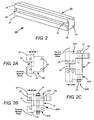
- the mirror-arrangement 10 includes a metal mirror-body 12 having a generally T-shaped cross-section, with a head portion 14 and a stem portion 16.
- a concave surface is generated, polished, and coated on the base of the stem portion to provide a concave reflective surface 18 having a radius of curvature R.
- the width L of the reflective surface is about equal to the width of the slab discharge for a turning mirror and somewhat shorter, for example between about 12% and 17% shorter than the discharge width for an output coupling mirror to allow output to be coupled out of the resonator.
- the height h of the reflective surface is typically about six times the height of the discharge, i.e., six times the separation of the discharge electrodes.
- Strips 17 of a metal different from that of body 12 are bolted to the underside of the head-portion of the body.
- the body 12 is made from copper and the strips 17 are made from stainless steel.
- the purpose of the strips is create a bimetallic stress that in steady-state operation, will compensate for differential expansion of the body that tends to increase the radius of curvature of the mirror due to a front-to-back thermal gradient in the mirror.
- Mirror arrangement 10 was designed for use in a slab laser having an average power of about 400 kilowatts (kW). The arrangement was successful in compensating long term curvature changes at that power to an extent described in the above referenced '577 publication.
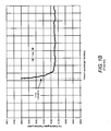
- FIG. 1B is a graph schematically illustrating pointing stability (far-field angular beam-position as a function of time) of a slab laser having a power of about 1.5kW average, and including mirrors designed according to the arrangement of FIG. 1 .
- Power output was at 60% duty cycle with at a (PRF) of 10 kHz.
- Output coupling was 12%. It can be seen that immediately after the laser was turned on, there was a beam deflection of 400 microradians ( ⁇ rad) in about 0.75 seconds with the beam assuming to a more or less constant deflection of about 450 ⁇ rad, within about one-second, over the time period of the graph.
- German Patent Application No. DE 3330626 European Patent Application Publication No. EP 1235090 , US Patent Application Publication No. US 2005/0046856 , and US Patent No. 3,836,236 all disclose a mirror structure for a laser beam.
- a mirror structure for reflecting a laser beam comprises a body have a reflective surface formed thereon for reflecting the laser beam.
- the surface becomes heated by the laser beam when in use.
- the body is configured so that the thermal neutral plane of the body is about aligned with the position of the reflective surface to minimize distortion of the curved surface due to the heating.
- the mirror body includes an elongated mirror member and a pair of thermal balancing members.
- the mirror member has a rectangular cross-section and the reflective surface is a concave front surface of the mirror member having a predetermined curvature.
- the thermal balancing members are attached to top and bottom surfaces of the mirror member and extend in a forward direction beyond the reflective surface of the mirror member.
- a finite element thermal analysis was conducted for a mirror arrangement similar to that which was responsible for the result depicted in the graph of FIG. 1B , in an attempt to determine a possible reason for the transient performance.
- the thermal analysis was directed in particular to determining the position of a "thermal neutral plane" (TNP) of the arrangement.
- the TNP of a structure is a well known fundamental concept. It is defined as a plane within a structure that undergoes no changes in shape due to heating of the structure. It corresponds generally with the geometric centroid of the structure, and is a plane when the structure has a uniform cross-section, whatever the cross-section shape.
- the net stress within the TNP is zero because on one side of the TNP, the material is stressed in tension while on the other side of the TNP, the material is in compression.
- the mass of material on each side of the TNP is about the same.
- heating occurs primarily as a result of absorption by the reflective surface of the mirror of a small but finite percentage of laser radiation circulating in the resonator. It should be borne in mind that with 12% output coupling and 1.5 kW average power output there are 11.0 kW circulating in a resonator, and a 0.5% absorbing surface will absorb about 62 W.
- thermal neutral plane of the mirror is located slightly behind the stem portion of the mirror as indicated in FIG. 1A . It can be seen that the distance of the TNP from the closest point (here the center) on the mirror is greater that the depth D of the reflective surface between the ends of the surface and the center or vertex of the surface.
- the thermal neutral plane should be moved forward to about coincide with the reflective surface of the mirror. This is not possible with a mirror body having the cross-section shape of prior art mirror arrangement 10, with or without the added strips.
- FIG. 2 and FIG. 2A schematically illustrates a mirror 20 in accordance with the present invention including a mirror body 22 having a somewhat U-shaped cross section with sides 24 extending beyond concave reflective surface 18.
- reflective surface 18 could be described as being the base of a channel 28 in mirror body 22.
- channels 26 are provided, extending through sides 24, to allow passage of a cooling fluid.
- This arrangement of sides extending beyond the reflective surface of the mirror body provide that the mirror body has mass forward of the reflecting surface. This is important for allowing dimensions of the body to be selected such that the thermal neutral plane about coincides with the ends of the reflective surface, the center or vertex of the reflective surface, or somewhere therebetween.
- the term "forward" as used here, refers to the direction in which the reflective surface faces.
- the TNP is depicted as being coincident with the ends of the reflective surface, but may generally be located in a plane between about coincident with the ends of the surface or about tangential to the center or vertex of the surface. It should be noted here, that while the present invention is described herein with reference to mirror-assemblies having a concave reflecting surface, principles of the present invention are equally applicable to a mirror-assembly having a convex surface as would be required to form a positive branch unstable resonator.
- the position of the TNP in the inventive elongated mirror-assembly is substantially independent of the heat load on the reflective surface and substantially independent of the coolant flow in channels 26.
- the TNP is, however, somewhat dependent on the volume, occupied by channels 26 and the position of the channels.
- thermal neutral plane can curved to be about coplanar with surface 18 along the entire length of the surface. Analysis suggests, however, that such a refinement will not provide a significantly different result from that when the thermal neutral plane is not curved but located in the above specified region.
- FIG. 2A While convenient for mechanical analysis, is somewhat impractical from a manufacturing standpoint, as it would be extremely difficult to polish and optically coat a reflective surface 18 in the base of a channel 28.
- a description of two practical body-forms for mirror 20 is set forth below with reference to FIGS 2B and 2C .
- FIG. 2B depicts a mirror-body assembly 22B in accordance with the present invention, fabricated in three sections.
- Concave reflective surface 18 of the mirror is generated polished and coated on an edge of a center bar 30 having a rectangular cross-section.
- the mirror surface has a depth D is described above in previous examples.
- a side-wall or side-bar 32 is clamped on each side of center bar 30 by a series of bolts 34 (only one visible in FIG. 2B . Cooling channels 26 extend through the side-bars.
- Side-bars 32A and 32B which can be described as thermal balancing bars, are attached after mirror surface 18 of the center bar has been polished and coated.
- Preferably the center section and the side-bars are made from the same material.
- a preferred material is copper.
- Portions 31 of side-bars 32 extend beyond the reflective surface to move the thermal neutral plane of the assembly forward. These portions are thicker than portions behind the reflective surface imparting somewhat L-shaped or stepped cross-section to the side-bars. Thickened portions 31 compensate for mass that is not in the space therebetween. In this example, again, the thermal neutral plane coincides with the ends of the reflective surface but may be anywhere in the above-discussed range.
- Side-bar 32A has a mounting boss 36 machined on a back edge thereof for mounting the mirror assembly to and end flange of a laser housing. Details of this mounting arrangement are discussed further hereinbelow.
- FIG. 2C depicts a mirror-body assembly 22C in accordance with the present invention, also fabricated in three sections.
- Mirror body is similar in principle to mirror body 22B with an exception that the three sections have a different cross-section shape from corresponding sections of assembly 22B.
- Center section 38 has a T-shaped cross-section of dimensions similar to those of prior-art mirror 10 of FIG. 1 .
- Side-bars 40A and 40B are L-shaped and configured to make thermal contact with lateral surfaces of the center section when clamped thereof by screws 42.
- Side-bar 40A has a mounting boss 36 machined on a back edge thereof for mounting the mirror assembly to an end flange of a laser housing as discussed above with reference to mirror body 22B.
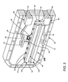
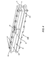
- FIG. 3 , FIG. 4 , and FIG. 5 schematically illustrate details of mounting a thermal neutral plane mirror in accordance with the present invention.
- a mirror having the mirror assembly configuration 22B of FIG. 2B is mounted on a flange 50, which is one end-flange of a hermetically sealable housing (not shown) for accommodating a slab-laser resonator, electrodes, and a lasing gas mixture.
- a grove 52 extends around the flange adjacent the periphery thereof and is configured to accept a metal "C-ring" or an indium "O-ring” to facilitate sealing. It is contemplated that a similar mirror and flange arrangement will be sealed to an opposite end of the housing to form the unstable resonator.
- Mirror assembly 22B is mounted on flange 50 by attaching mounting boss 36 on side-bar 32A (see FIG. 4 for details) to a post 54 (see FIG. 5 for detail) monolithically attached to flange 50 via an integrated flexible membrane 56 formed by machining the flange from the back side.
- This provides that the mounted mirror-assembly can be adjusted in two transverse axes for aligning the reflective surface thereof in the resonator.
- This method of mounting in addition to allowing alignment of the mirror surface from outside the laser housing, reduces the probability of distorting the reflective surface by the attachment process.
- the method also allows coolant channels to be placed within the length of the side-bars rather than within the center section further reducing the possibility of distorting the reflective surface.
- a detailed description of the alignment arrangement is not necessary for understanding principles of the present invention. A detailed description can be found in the above referenced '577 publication.
- Cooling arrangements for mirror-assembly 22B are as follows.
- a main (outer) coolant manifold (not shown) located on the backside of the flange splits and directs coolant flow to upper and lower secondary (inner) coolant manifolds 60 which extend through the flange and are sealed to the flange by gaskets 62.
- the secondary coolant manifolds are each preferably made from gold-plated copper.
- An outlet of each inner coolant manifold directs coolant into a conduit 64 which directs the flow into the center inlet/outlet port 66 of each of upper and lower mirror side bars 32A and 32B.
- the coolant is circulated through channels 26 in the side-bars by U-shaped conduits 68 and 70.
- the coolant returns to port 66 and is direct from the port by a conduit 72 back to the inner coolant manifold which directs the coolant back to the outer manifold.
- FIG. 6 is a graph schematically illustrating measured far-field angular-position as a function of time in one example of a laser incorporating highly reflecting and output coupling mirror-assemblies having the general configuration of the mirror of FIG. 3 (solid curve), compared with the measured far-field angular-position as a function of time of a similar laser having the prior-art mirror configuration of FIG. 1 (dashed curve).
- the laser in each case is a sealed-off CO 2 slab laser, with the mirrors forming a negative branch unstable resonator.
- the laser output-power in each case was approximately 1.5kW average at 60% duty cycle with at a (PRF) of 10 kHz.
- the output coupling for each example was 12%. It can be seen that the inventive mirror configuration essentially completely eliminates the transient deflection "spike" experienced with the prior art.
- the thermal time constant of the mirror averages out pulse to pulse deflection effects at the10 kHz PRF.
- the length of the mirror is 159 mm.
- the radius of curvature of the mirror is 1044.55.
- the center section 30 has a thickness of 8.0 mm.
- Side-bars 32A and 32 each have a thickness of 9.7 mm at the forward edge and a thickness of 7.6 mm at the rearward edge.
- the total width of each side-par is 25.4 mm, with the forward 9.7 mm-thick portion having a width of 10 mm.
- Mounting boss 36 on the upper side-bar 36 has a width of 10.2 mm and a length of 20.3 mm. The absorption of each of the reflective surfaces is estimated at about 0.2%.
- Cooling channels 26 have a diameter of 0.125 inches (3.2 mm) and are located 0.118 inches (3.0 mm) and 0.160 inches (4.06 mm) from the front surface of the sidebars.
- the length of the output coupling mirror is 132 mm and the radius of curvature is 887.85 mm
- the deflection measurements were made using a Pyrocam TM III pyroelectric array camera, available from Ophir-Spiricon Inc. of Logan, Utah.
- the camera recording-speed was approximately 25 frames per sec.
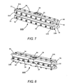
- FIG. 7 is a three dimensional view from the front, schematically illustrating yet another example of a mirror-assembly 22D in accordance with the present invention.
- Assembly 22D is constructed similarly to the example assembly 2B of FIG. 3 with an exception that on a forward-facing face of each of side-bars 32A and 32B are attached strips 33A and 33B respectively of a material (metal) different from that of the side-bars.
- the terminology forward-facing, here, and in claims appended hereto means facing into the resonator (not shown) of which reflective surface 18 is one end mirror, i.e., facing in the direction that the reflective surface faces.
- the strips are attached to the side-bars by screws 35.
- the length of screws 35 should be selected to be short enough such that screws do not impeded the coolant channel in the sidebar.
- the strips are formed from a material that has a lower coefficient of thermal expansion than the metal material of the bars.
- Stainless steel is one suitable material for strips 33A and 33B when the sidebars are made from copper.
- the bars and strips will exhibit the bimetallic effect.
- the bimetallic effect tends to cause the concave mirror to become more concave.
- the differential heating induced by absorption of some of the laser energy tends to causes the mirror to become less concave.
- FIG. 8 is a three-dimensional view from the rear, schematically illustrating still another example 22E of a mirror assembly in accordance with the present invention.
- Mirror assembly constructed similarly to assembly of FIG. 2B of FIG. 3 but wherein center section 30 of the assembly has a strip 39 of material attached by screws 35 to a rearward-facing, surface of the center section, the strip being of a material different from that of center-section 30.
- the coefficient of thermal expansion of the strip is selected to be greater than the coefficient of thermal expansion of the center section to counter the effects of the thermal gradient induced by heating the front surface of the mirror.
- Aluminum is a suitable material for strip 39 when center section 30 is made from copper.
- This arrangement of strips on the side bars or the center section provides for bi-metallic effects which offer an additional degree of freedom in the design of the inventive mirror-assembly.
- This additional freedom could, for example, be useful in providing a design which minimizes or eliminates a gradual change in curvature of reflective surface 18 in extended operation of a laser over a time much longer than the measurement time of FIG. 6 .
- inventive mirror-assemblies in FIGS 3 , 4 , 7 and 8 , that components of the assemblies have dimensions that are relatively to scale. Exemplary dimensions for a tested embodiment of the mirror are provided above. Based on these relative and actual dimensions, those skilled in the art to which the present invention pertains may readily determine corresponding starting-shapes for refinement in finite element analysis (FEA) software to determine thermal neutral plane positions for embodiments of the mirrors for different resonator configurations and selected materials. Using such software, those skilled in the art may determine other mirror-assembly arrangements that will provide for a thermal neutral plane about coincident with a reflecting surface without departing from the scope of the present invention.
- FEA finite element analysis
Description
- The present invention relates in general to gas discharge lasers. The invention relates in particular to the design and construction of mirrors for hermetically sealed, high power, diffusion-cooled, carbon dioxide (CO2) slab lasers.
- CO2 slab lasers include a pair of rectangular, plane, metal electrodes mounted within a sealed housing containing a laser gas mixture including CO2 and inert gases. The electrodes are parallel to each other and spaced close together to define a slab-shaped discharge region. RF power is used to excite the gas mixture for generating laser radiation. A description of such a laser can be found in
U.S. Patent No. 5,140,606 assigned to the assignee of the present invention. - This type of laser typically includes a hybrid optical resonator. The resonator is an unstable resonator in the width-dimension of the parallel spaced apart electrodes and a waveguide type resonator in a dimension perpendicular to the plane of the electrodes. In early models the unstable resonator was a positive branch unstable resonator. In later models a negative branch unstable resonator was preferred.
- A positive branch unstable resonator designs is about an order of magnitude more difficult to align than a negative branch unstable resonator but is much less sensitive to output beam pointing variations that result from changes in the curvature of mirrors of the resonator, which changes result in turn from changes in the temperature of the mirror. A negative branch unstable resonator is much more sensitive to temperature induced mirror curvature changes. Beam-pointing variations are a problem in most applications where the laser beam must be steered or directed accurately to a particular location or locations on a workpiece.
- Analysis indicates pointing-variations of a laser beam scale directly with the width of a negative branch unstable resonator and inversely as the square of its length. Designing a shorter industrial CO2 laser is looked upon with favor in the industrial application of CO2 lasers provided beam quality is not compromised. As the length of the discharge is made shorter, the width of the discharge needs to be increased to maintain the same discharge area required to obtain the same laser output power.
- A negative branch unstable resonator includes an output coupling mirror and a return mirror each having concave reflecting surfaces. The surfaces are made highly reflecting by depositing multilayer thin film coatings on the surfaces. The output coupling mirror is shorter than the return mirror in order to provide for an output for the laser beam past the mirror. The return mirror normally extends over the entire width of the discharge generated by the parallel facing electrodes. The output coupling mirror is shorter to allow a portion of the radiation circulating in the resonator to bypass the mirror as output radiation.
- When a laser beam is circulating in the resonator the reflecting surfaces of the mirrors are heated as the laser mirrors have a small, but finite, optical absorption. When the laser is suddenly turned on to a sufficiently high full power, rapid heating of the reflective surface causes the surface to suddenly distort. The mirror becomes suddenly less concave, i.e., suddenly has an increased radius of curvature. This sudden increase in the curvature radius causes the laser beam to suddenly point in another direction. The radius of curvature quickly recovers to nearly its original radius as the fast transient heating is quickly conducted away by the mirror body.
- The heat from the reflecting surface eventually propagates through the thickness of the mirror body establishing a temperature gradient between the front and back surfaces of the mirror. This thermal gradient further causes the mirror to become less concave until a steady state mirror curvature is reached at a given laser power. The back of the mirror is typically attached to a large metal plate, which is an end flange of a sealed housing in which the resonator and laser gas are enclosed. This causes the back of the mirror to be cooler than the front surface. The difference in the time response between the transient and steady-state mirror radius change is over two orders of magnitude.
- Under low laser pulse repetition frequency (PRF) operation, the mirror radius changes directly in response to the changes in the PRF. As the PRF increases, the thermal time constant of the mirror assembly begins to average out the time variations in the mirror radius of the mirror. The PRF at which the averaging begins is dependent on the thermal time constant of the material from which the mirror is made and the mass of the mirror.
- One arrangement directed at minimizing mirror curvature changes under steady state operation is described in
U.S. Patent Application No. 12/168,376, filed July 7, 2008 U.S Pre-Grant Publication No. 20090034577 ), assigned to the assignee of the present invention. This result is achieved by designing a mirror with a mirror body of a particular shape with strips of a material different from that of the body attached to the body to provide a compensating bi-metallic effect. An example of the arrangement is depicted inFIG. 1 and FIG. 1A . - Here, the mirror-
arrangement 10 includes a metal mirror-body 12 having a generally T-shaped cross-section, with ahead portion 14 and astem portion 16. A concave surface is generated, polished, and coated on the base of the stem portion to provide a concavereflective surface 18 having a radius of curvature R. Typically, the width L of the reflective surface is about equal to the width of the slab discharge for a turning mirror and somewhat shorter, for example between about 12% and 17% shorter than the discharge width for an output coupling mirror to allow output to be coupled out of the resonator. The height h of the reflective surface is typically about six times the height of the discharge, i.e., six times the separation of the discharge electrodes. -
Strips 17 of a metal different from that ofbody 12 are bolted to the underside of the head-portion of the body. In an example described in the patent publication, thebody 12 is made from copper and thestrips 17 are made from stainless steel. The purpose of the strips is create a bimetallic stress that in steady-state operation, will compensate for differential expansion of the body that tends to increase the radius of curvature of the mirror due to a front-to-back thermal gradient in the mirror. -
Mirror arrangement 10 was designed for use in a slab laser having an average power of about 400 kilowatts (kW). The arrangement was successful in compensating long term curvature changes at that power to an extent described in the above referenced '577 publication. - Subsequently, a mirror having this configuration was used in a laser having an average output power of 1.5 kW (about 4 times the original design power). In this case, a very strong transient change in beam pointing was observed immediately after turning on the laser at the 1.5 kW power.
-
FIG. 1B is a graph schematically illustrating pointing stability (far-field angular beam-position as a function of time) of a slab laser having a power of about 1.5kW average, and including mirrors designed according to the arrangement ofFIG. 1 . Power output was at 60% duty cycle with at a (PRF) of 10 kHz. Output coupling was 12%. It can be seen that immediately after the laser was turned on, there was a beam deflection of 400 microradians (µrad) in about 0.75 seconds with the beam assuming to a more or less constant deflection of about 450 µrad, within about one-second, over the time period of the graph. - In most laser-processing operations a work-piece is positioned in the laser-beam path before the laser is turned on, and the material processing occurs sufficiently quickly that beam pointing uncertainty of even one-second duration is significant and can adversely affect the processing operation. Accordingly, it would be advantageous to minimize if not altogether eliminate, transient pointing variations, however short, of the type exemplified by the graph of
FIG. 1B . - German Patent Application No.
DE 3330626 , European Patent Application Publication No.EP 1235090 , US Patent Application Publication No.US 2005/0046856 , andUS Patent No. 3,836,236 all disclose a mirror structure for a laser beam. - The invention is defined in
independent claim 1 to which reference should now be made. Preferred features are set forth in the dependent claims. - In one embodiment of the present invention, a mirror structure for reflecting a laser beam comprises a body have a reflective surface formed thereon for reflecting the laser beam. The surface becomes heated by the laser beam when in use. The body is configured so that the thermal neutral plane of the body is about aligned with the position of the reflective surface to minimize distortion of the curved surface due to the heating.
- In a preferred embodiment of the inventive mirror structure, the mirror body includes an elongated mirror member and a pair of thermal balancing members. The mirror member has a rectangular cross-section and the reflective surface is a concave front surface of the mirror member having a predetermined curvature. The thermal balancing members are attached to top and bottom surfaces of the mirror member and extend in a forward direction beyond the reflective surface of the mirror member.
- The alignment of the thermal neutral plane with the reflective surface minimizes changes to the mirror curvature due to heating. Experimental evaluation of a laser including such mirrors indicates that the above discussed transient spike in beam pointing is essentially eliminated by use of the inventive mirrors.
- The accompanying drawings, which are incorporated in and constitute a part of the specification, schematically illustrate a preferred embodiment of the present invention, and together with the general description given above and the detailed description of the preferred embodiment given below, serve to explain principles of the present invention.
-
FIG. 1 is a three dimensional view schematically illustrating a prior-art CO2 slab-laser mirror configured to minimize thermally-induced curvature changes of a reflecting surface thereof. -
FIG. 1A is and end elevation view seen generally in thedirection 1A-1A ofFIG. 1 , schematically illustrating further detail of the mirror ofFIG. 1 . -
FIG. 1B is a graph schematically illustrating far-field angular position as a function of time for a beam from a 1.5 kW average power CO2 slab-laser incorporating a mirror similar to the mirror ofFIG.1 . -
FIG. 2 is a three-dimensional view schematically illustrating a preferred embodiment of a CO2 slab-laser mirror in accordance with the present invention configured to minimize thermally-induced curvature changes of a reflecting surface thereof. -
FIG. 2A is an end-elevation view schematically illustrating further detail of the mirror ofFIG. 2 . -
FIG. 2B is an end-elevation view schematically illustrating one example of a preferred alternative construction of the mirror ofFIG. 2 including a center section on which a reflective surface is formed and having a sidebar clamped on each side-of the center section extending beyond the reflective surface. -
FIG. 2C is an end-elevation view schematically illustrating another example of a preferred alternative construction of the mirror ofFIG. 2 . -
FIG. 3 is a three-dimensional view, partly in cross-section, schematically illustrating a mirror-assembly in accordance with the present invention constructed according to the example ofFIG. 2B and mounted on a mirror-mounting post of one example of an end-flange of a CO2 slab-laser housing. -
FIG. 4 is a three-dimensional view from the rear schematically illustrating further detail of the mirror-assembly ofFIG. 3 . -
FIG. 5 is a three-dimensional view schematically illustrating details of the mounting post ofFIG. 3 . -
FIG. 6 is a graph schematically illustrating far-field angular-position as a function of time in one example of a laser incorporating the mirror ofFIG. 3 compared with the far-field angular-position as a function of time of the prior-art mirror ofFIG. 1B . -
FIG. 7 is a three dimensional view from the front, schematically illustrating yet another example of a mirror assembly in accordance with the present invention constructed similarly to the example ofFIG. 2B but wherein the side bars each have a strip of material attached thereto, each strip being of a material different from that of the side-bar. -
FIG. 8 is a three dimensional view from the rear, schematically illustrating yet another example of a mirror assembly in accordance with the present invention constructed similarly to the example ofFIG. 2B but wherein the center section has a strip of material attached thereto, the strip being of a material different from that of the center section. - A finite element thermal analysis (FEA) was conducted for a mirror arrangement similar to that which was responsible for the result depicted in the graph of
FIG. 1B , in an attempt to determine a possible reason for the transient performance. The thermal analysis was directed in particular to determining the position of a "thermal neutral plane" (TNP) of the arrangement. - The TNP of a structure is a well known fundamental concept. It is defined as a plane within a structure that undergoes no changes in shape due to heating of the structure. It corresponds generally with the geometric centroid of the structure, and is a plane when the structure has a uniform cross-section, whatever the cross-section shape. When the structure is heated from one side of the TNP, the net stress within the TNP is zero because on one side of the TNP, the material is stressed in tension while on the other side of the TNP, the material is in compression. The mass of material on each side of the TNP is about the same.
- In the case of a slab laser resonator mirror, heating occurs primarily as a result of absorption by the reflective surface of the mirror of a small but finite percentage of laser radiation circulating in the resonator. It should be borne in mind that with 12% output coupling and 1.5 kW average power output there are 11.0 kW circulating in a resonator, and a 0.5% absorbing surface will absorb about 62 W.
- The result of the above-mentioned analysis indicated that the thermal neutral plane of the mirror is located slightly behind the stem portion of the mirror as indicated in
FIG. 1A . It can be seen that the distance of the TNP from the closest point (here the center) on the mirror is greater that the depth D of the reflective surface between the ends of the surface and the center or vertex of the surface. - It was decided that in order to eliminate, or at least mitigate, transient pointing effects associated with
mirror 10 ofFIG. 1 , the thermal neutral plane should be moved forward to about coincide with the reflective surface of the mirror. This is not possible with a mirror body having the cross-section shape of priorart mirror arrangement 10, with or without the added strips. -
FIG. 2 and FIG. 2A schematically illustrates amirror 20 in accordance with the present invention including amirror body 22 having a somewhat U-shaped cross section withsides 24 extending beyond concavereflective surface 18. Considered from another viewpoint,reflective surface 18 could be described as being the base of achannel 28 inmirror body 22. Preferably,channels 26 are provided, extending throughsides 24, to allow passage of a cooling fluid. This arrangement of sides extending beyond the reflective surface of the mirror body provide that the mirror body has mass forward of the reflecting surface. This is important for allowing dimensions of the body to be selected such that the thermal neutral plane about coincides with the ends of the reflective surface, the center or vertex of the reflective surface, or somewhere therebetween. The term "forward" as used here, refers to the direction in which the reflective surface faces. - In
FIG. 2A the TNP is depicted as being coincident with the ends of the reflective surface, but may generally be located in a plane between about coincident with the ends of the surface or about tangential to the center or vertex of the surface. It should be noted here, that while the present invention is described herein with reference to mirror-assemblies having a concave reflecting surface, principles of the present invention are equally applicable to a mirror-assembly having a convex surface as would be required to form a positive branch unstable resonator. - It is believed, without being limited to a particular hypothesis, that the position of the TNP in the inventive elongated mirror-assembly is substantially independent of the heat load on the reflective surface and substantially independent of the coolant flow in
channels 26. The TNP is, however, somewhat dependent on the volume, occupied bychannels 26 and the position of the channels. - It should be noted here that if the top surfaces of
sides 24 are curved to match the curvature ofreflective surface 18 the thermal neutral plane can curved to be about coplanar withsurface 18 along the entire length of the surface. Analysis suggests, however, that such a refinement will not provide a significantly different result from that when the thermal neutral plane is not curved but located in the above specified region. - Those skilled in the art will recognize that the one-piece the body form of
FIG. 2A , while convenient for mechanical analysis, is somewhat impractical from a manufacturing standpoint, as it would be extremely difficult to polish and optically coat areflective surface 18 in the base of achannel 28. A description of two practical body-forms formirror 20 is set forth below with reference toFIGS 2B and 2C . -
FIG. 2B depicts a mirror-body assembly 22B in accordance with the present invention, fabricated in three sections. Concavereflective surface 18 of the mirror is generated polished and coated on an edge of acenter bar 30 having a rectangular cross-section. The mirror surface has a depth D is described above in previous examples. A side-wall or side-bar 32 is clamped on each side ofcenter bar 30 by a series of bolts 34 (only one visible inFIG. 2B .Cooling channels 26 extend through the side-bars. - Side-
bars mirror surface 18 of the center bar has been polished and coated. Preferably the center section and the side-bars are made from the same material. A preferred material is copper. -
Portions 31 of side-bars 32 extend beyond the reflective surface to move the thermal neutral plane of the assembly forward. These portions are thicker than portions behind the reflective surface imparting somewhat L-shaped or stepped cross-section to the side-bars.Thickened portions 31 compensate for mass that is not in the space therebetween. In this example, again, the thermal neutral plane coincides with the ends of the reflective surface but may be anywhere in the above-discussed range. Side-bar 32A has a mountingboss 36 machined on a back edge thereof for mounting the mirror assembly to and end flange of a laser housing. Details of this mounting arrangement are discussed further hereinbelow. -
FIG. 2C depicts a mirror-body assembly 22C in accordance with the present invention, also fabricated in three sections. Mirror body is similar in principle to mirrorbody 22B with an exception that the three sections have a different cross-section shape from corresponding sections ofassembly 22B.Center section 38 has a T-shaped cross-section of dimensions similar to those of prior-art mirror 10 ofFIG. 1 . Side-bars screws 42. Side-bar 40A has a mountingboss 36 machined on a back edge thereof for mounting the mirror assembly to an end flange of a laser housing as discussed above with reference to mirrorbody 22B. -
FIG. 3 ,FIG. 4 , andFIG. 5 schematically illustrate details of mounting a thermal neutral plane mirror in accordance with the present invention. Here, a mirror having themirror assembly configuration 22B ofFIG. 2B is mounted on aflange 50, which is one end-flange of a hermetically sealable housing (not shown) for accommodating a slab-laser resonator, electrodes, and a lasing gas mixture. Agrove 52 extends around the flange adjacent the periphery thereof and is configured to accept a metal "C-ring" or an indium "O-ring" to facilitate sealing. It is contemplated that a similar mirror and flange arrangement will be sealed to an opposite end of the housing to form the unstable resonator. -
Mirror assembly 22B is mounted onflange 50 by attaching mountingboss 36 on side-bar 32A (seeFIG. 4 for details) to a post 54 (seeFIG. 5 for detail) monolithically attached toflange 50 via an integratedflexible membrane 56 formed by machining the flange from the back side. This provides that the mounted mirror-assembly can be adjusted in two transverse axes for aligning the reflective surface thereof in the resonator. This method of mounting, in addition to allowing alignment of the mirror surface from outside the laser housing, reduces the probability of distorting the reflective surface by the attachment process. The method also allows coolant channels to be placed within the length of the side-bars rather than within the center section further reducing the possibility of distorting the reflective surface. A detailed description of the alignment arrangement is not necessary for understanding principles of the present invention. A detailed description can be found in the above referenced '577 publication. - The narrow length of mounting
boss 36, relative to the length of the mirror-assembly, minimizes mechanical and thermal communication between themirror assembly 22B and theflange 50. This provides that the mirror assembly can be treated as a stand-alone (essentially isolated) assembly from the point of view of determining the TNP location. - Cooling arrangements for mirror-
assembly 22B are as follows. A main (outer) coolant manifold (not shown) located on the backside of the flange splits and directs coolant flow to upper and lower secondary (inner)coolant manifolds 60 which extend through the flange and are sealed to the flange bygaskets 62. The secondary coolant manifolds are each preferably made from gold-plated copper. An outlet of each inner coolant manifold directs coolant into aconduit 64 which directs the flow into the center inlet/outlet port 66 of each of upper and lowermirror side bars channels 26 in the side-bars byU-shaped conduits conduit 72 back to the inner coolant manifold which directs the coolant back to the outer manifold. -
FIG. 6 is a graph schematically illustrating measured far-field angular-position as a function of time in one example of a laser incorporating highly reflecting and output coupling mirror-assemblies having the general configuration of the mirror ofFIG. 3 (solid curve), compared with the measured far-field angular-position as a function of time of a similar laser having the prior-art mirror configuration ofFIG. 1 (dashed curve). The laser in each case is a sealed-off CO2 slab laser, with the mirrors forming a negative branch unstable resonator. The laser output-power in each case was approximately 1.5kW average at 60% duty cycle with at a (PRF) of 10 kHz. The output coupling for each example was 12%. It can be seen that the inventive mirror configuration essentially completely eliminates the transient deflection "spike" experienced with the prior art. The thermal time constant of the mirror averages out pulse to pulse deflection effects at the10 kHz PRF. - Dimensions of one of the inventive mirrors, made from gold plated copper, are as follows. The length of the mirror is 159 mm. The radius of curvature of the mirror is 1044.55. The
center section 30 has a thickness of 8.0 mm. Side-bars 32A and 32 each have a thickness of 9.7 mm at the forward edge and a thickness of 7.6 mm at the rearward edge. The total width of each side-par is 25.4 mm, with the forward 9.7 mm-thick portion having a width of 10 mm. Mountingboss 36 on the upper side-bar 36 has a width of 10.2 mm and a length of 20.3 mm. The absorption of each of the reflective surfaces is estimated at about 0.2%.Cooling channels 26 have a diameter of 0.125 inches (3.2 mm) and are located 0.118 inches (3.0 mm) and 0.160 inches (4.06 mm) from the front surface of the sidebars. The length of the output coupling mirror is 132 mm and the radius of curvature is 887.85 mm - The deflection measurements were made using a Pyrocam™ III pyroelectric array camera, available from Ophir-Spiricon Inc. of Logan, Utah. The camera recording-speed was approximately 25 frames per sec.
-
FIG. 7 is a three dimensional view from the front, schematically illustrating yet another example of a mirror-assembly 22D in accordance with the present invention.Assembly 22D is constructed similarly to the example assembly 2B ofFIG. 3 with an exception that on a forward-facing face of each of side-bars strips reflective surface 18 is one end mirror, i.e., facing in the direction that the reflective surface faces. The strips are attached to the side-bars byscrews 35. The length ofscrews 35 should be selected to be short enough such that screws do not impeded the coolant channel in the sidebar. In this embodiment, the strips are formed from a material that has a lower coefficient of thermal expansion than the metal material of the bars. Stainless steel is one suitable material forstrips - Because of the differential expansion rates of the two materials, the bars and strips will exhibit the bimetallic effect. In this case, the bimetallic effect tends to cause the concave mirror to become more concave. In contrast, the differential heating induced by absorption of some of the laser energy tends to causes the mirror to become less concave. By proper selection of the thickness and size of the steel strips, the two effects can be balanced, thus minimizing distortion.
-
FIG. 8 is a three-dimensional view from the rear, schematically illustrating still another example 22E of a mirror assembly in accordance with the present invention. Mirror assembly constructed similarly to assembly ofFIG. 2B ofFIG. 3 but whereincenter section 30 of the assembly has astrip 39 of material attached byscrews 35 to a rearward-facing, surface of the center section, the strip being of a material different from that of center-section 30. In this embodiment, the coefficient of thermal expansion of the strip is selected to be greater than the coefficient of thermal expansion of the center section to counter the effects of the thermal gradient induced by heating the front surface of the mirror. Aluminum is a suitable material forstrip 39 whencenter section 30 is made from copper. - This arrangement of strips on the side bars or the center section provides for bi-metallic effects which offer an additional degree of freedom in the design of the inventive mirror-assembly. This additional freedom could, for example, be useful in providing a design which minimizes or eliminates a gradual change in curvature of
reflective surface 18 in extended operation of a laser over a time much longer than the measurement time ofFIG. 6 . - Those skilled in the art to which the present invention pertain will recognize, from the representation of inventive mirror-assemblies in
FIGS 3 ,4 ,7 and 8 , that components of the assemblies have dimensions that are relatively to scale. Exemplary dimensions for a tested embodiment of the mirror are provided above. Based on these relative and actual dimensions, those skilled in the art to which the present invention pertains may readily determine corresponding starting-shapes for refinement in finite element analysis (FEA) software to determine thermal neutral plane positions for embodiments of the mirrors for different resonator configurations and selected materials. Using such software, those skilled in the art may determine other mirror-assembly arrangements that will provide for a thermal neutral plane about coincident with a reflecting surface without departing from the scope of the present invention. - The present invention is described above in terms of preferred and other embodiments. The invention is not limited, however, to the embodiments described and depicted. Rather, the invention is limited only by the claims appended hereto.
Claims (12)
- A mirror structure for reflecting a laser beam comprising:an elongated mirror member (20) having a curved front surface (18) for reflecting a laser beam, said surface (18) becoming heated by the laser beam when in use;the mirror structure characterized by further comprising:a pair of elongated thermal balancing members (32A, 32B) mounted along top and bottom surfaces of the mirror member (20), with the front portion of each balancing member (32A, 32B) extending in a forward direction beyond the curved front surface (18) of the mirror member (20), with the thermal balancing members (32A, 32B) being configured to align the thermal neutral plane of the structure close to the curved front surface (18) to minimize distortion of the curved surface due to the heating.
- The mirror structure of claim 1, wherein the rear surface of one of the balancing members (32A) includes a mounting boss (36) for connecting the structure to a mirror flange (50) of a laser.
- The mirror structure of claim 2, wherein the mounting boss (36) has a length less than the length of the thermal balancing members (32A, 32B), to minimize thermal communication between the mirror structure and the flange (50).
- The mirror structure of claim 1, wherein the thermal balancing members (32A, 32B) are fluid cooled.
- The mirror structure of claim 1, wherein the thermal balancing members (32A, 32B) have an L-shaped cross-section with the front portion thicker than the rear portion and with the thicker front portion extending beyond the curved front surface (18) of the mirror member (20).
- The mirror structure of claim 1, wherein the curved front surface (18) is a concave surface.
- The mirror structure of claim 6, wherein the thermal neutral plane is aligned between coincident with the ends of the curved front surface (18) and tangential to the vertex of the concave surface of the curved front surface (18).
- The mirror structure of claim 1, wherein the mirror member (20) and the balancing members (32A, 32B) are made from the same material.
- The mirror structure of claim 8, wherein the material of the mirror member (20) and the balancing members (32A, 32B) is copper.
- The mirror structure of claim 1 or 8, wherein the mirror member (20) and the balancing members (32A, 32B) are formed as one-piece.
- The mirror structure of claim 1, wherein the balancing members (32A, 32B) are made from a first material and a strip (33A, 33B) of a second material different from the first material is attached to a forward facing surface of each of the balancing members (32A, 32B) for further minimizing the distortion of the curved front surface (18) due to the heating.
- The mirror structure of claim 11, wherein the balancing members (32A, 32B) are made from copper and the strips (33A, 33B) are made from stainless steel.
Applications Claiming Priority (3)
| Application Number | Priority Date | Filing Date | Title |
|---|---|---|---|
| US14323809P | 2009-01-08 | 2009-01-08 | |
| US12/464,442 US8201954B2 (en) | 2009-01-08 | 2009-05-12 | Compensation for transient heating of laser mirrors |
| PCT/US2009/069194 WO2010080650A2 (en) | 2009-01-08 | 2009-12-22 | Compensation for transient heating of laser mirrors |
Publications (2)
| Publication Number | Publication Date |
|---|---|
| EP2382694A2 EP2382694A2 (en) | 2011-11-02 |
| EP2382694B1 true EP2382694B1 (en) | 2015-01-21 |
Family
ID=42311534
Family Applications (1)
| Application Number | Title | Priority Date | Filing Date |
|---|---|---|---|
| EP09801629.8A Active EP2382694B1 (en) | 2009-01-08 | 2009-12-22 | Compensation for transient heating of laser mirrors |
Country Status (6)
| Country | Link |
|---|---|
| US (1) | US8201954B2 (en) |
| EP (1) | EP2382694B1 (en) |
| JP (1) | JP5604447B2 (en) |
| KR (1) | KR101674231B1 (en) |
| CN (1) | CN102273025B (en) |
| WO (1) | WO2010080650A2 (en) |
Family Cites Families (18)
| Publication number | Priority date | Publication date | Assignee | Title |
|---|---|---|---|---|
| US3836236A (en) | 1972-11-24 | 1974-09-17 | Gte Sylvania Inc | Mirror mount for high power lasers |
| US4287421A (en) | 1978-06-07 | 1981-09-01 | Jersey Nuclear-Avco Isotopes, Inc. | Compensation of thermal expansion in mirrors for high power radiation beams |
| US4266857A (en) * | 1980-01-30 | 1981-05-12 | The United States Of America As Represented By The Secretary Of The Treasury | Liquid or gas cooled flexible beam-compensating adjustable cylindrical mirror |
| DE3330626A1 (en) | 1983-08-25 | 1987-06-25 | Wisotzki Juergen | Mirror for laser technology |
| JPS6361171U (en) * | 1986-10-08 | 1988-04-22 | ||
| US4719639B1 (en) | 1987-01-08 | 1994-06-28 | Boreal Laser Inc | Carbon dioxide slab laser |
| DE3900467C2 (en) | 1989-01-10 | 1995-09-07 | Trumpf Lasertechnik Gmbh | Device with a mirror head |
| US5048048A (en) | 1989-08-11 | 1991-09-10 | Mitsubishi Denki K.K. | Gas laser device |
| US5140606A (en) | 1990-10-12 | 1992-08-18 | Coherent, Inc. | RF excited CO2 slab waveguide laser |
| DE4428194C2 (en) * | 1994-08-09 | 1998-02-12 | Rofin Sinar Laser Gmbh | Laser system with a compensated mirror optic |
| JP3648350B2 (en) * | 1997-04-07 | 2005-05-18 | 株式会社リコー | Optical element |
| US6255599B1 (en) | 1997-08-18 | 2001-07-03 | Ibm | Relocating the neutral plane in a PBGA substrate to eliminate chip crack and interfacial delamination |
| JPH11271595A (en) * | 1998-03-24 | 1999-10-08 | Aida Eng Ltd | Mirror holder device |
| US6912052B2 (en) | 2000-11-17 | 2005-06-28 | Cymer, Inc. | Gas discharge MOPA laser spectral analysis module |
| DE50100494D1 (en) | 2001-02-22 | 2003-09-18 | Trumpf Lasertechnik Gmbh | Device for beam guidance of a laser beam |
| US20020167976A1 (en) * | 2001-04-04 | 2002-11-14 | Seguin Vernon A. | Thermally efficient laser head |
| DE10201334A1 (en) * | 2002-01-16 | 2003-08-14 | Rofin Sinar Laser Gmbh | Mirror for a laser beam |
| US7664159B2 (en) | 2007-07-31 | 2010-02-16 | Coherent, Inc. | Thermal distortion compensation for laser mirrors |
-
2009
- 2009-05-12 US US12/464,442 patent/US8201954B2/en active Active
- 2009-12-22 CN CN200980154321.4A patent/CN102273025B/en active Active
- 2009-12-22 KR KR1020117018375A patent/KR101674231B1/en active IP Right Grant
- 2009-12-22 JP JP2011545367A patent/JP5604447B2/en active Active
- 2009-12-22 WO PCT/US2009/069194 patent/WO2010080650A2/en active Application Filing
- 2009-12-22 EP EP09801629.8A patent/EP2382694B1/en active Active
Also Published As
| Publication number | Publication date |
|---|---|
| WO2010080650A2 (en) | 2010-07-15 |
| WO2010080650A3 (en) | 2010-08-26 |
| EP2382694A2 (en) | 2011-11-02 |
| CN102273025A (en) | 2011-12-07 |
| JP2012514869A (en) | 2012-06-28 |
| US8201954B2 (en) | 2012-06-19 |
| CN102273025B (en) | 2015-02-11 |
| KR101674231B1 (en) | 2016-11-08 |
| KR20110111471A (en) | 2011-10-11 |
| JP5604447B2 (en) | 2014-10-08 |
| US20100172042A1 (en) | 2010-07-08 |
Similar Documents
| Publication | Publication Date | Title |
|---|---|---|
| EP1623788B1 (en) | Laser cutting apparatus | |
| US5751750A (en) | Laser system and method with thermally compensated optics | |
| EP0675579B1 (en) | Improved slab-waveguide CO2 laser | |
| EP0904616B1 (en) | Rf excited waveguide laser | |
| JP6722761B2 (en) | High Power Planar Waveguide (PWG) Pump Head with Modular Components for High Power Laser Systems | |
| JP2018538688A (en) | Integrated pump optical homogenizer and signal injector for high power laser systems | |
| US5805625A (en) | Laser | |
| US7965757B2 (en) | Thermal distortion compensation for laser mirrors | |
| EP2382694B1 (en) | Compensation for transient heating of laser mirrors | |
| JPH04259270A (en) | High-output strip waveguide laser | |
| US5881088A (en) | Face-cooled high-power laser optic cell | |
| US3817606A (en) | Mirror for high power lasers and method of fabricating same | |
| Habich et al. | Industrial 30-kW CO2 laser with fast axial gas flow and rf excitation | |
| Grigoriev et al. | Stabilized single-mode dye laser | |
| EP2166626A1 (en) | Method of reducing a divergence of a laser beam | |
| US20040184503A1 (en) | Narrow band electric discharge gas laser having improved beam direction stability | |
| JPH1168213A (en) | Q switch co2 laser device | |
| JP2003338647A (en) | Laser oscillator | |
| JP4045952B2 (en) | Gas laser oscillator | |
| JP2002237632A (en) | Slab laser and laser apparatus | |
| Rabczuk et al. | High-power cw CO2 laser beam properties in a system with a variable focal length mirror | |
| JP2000022244A (en) | Solid-state laser device | |
| Rabczuk | Use of adaptive optics elements in the industrial cw CO2 laser for control of the output beam characteristics | |
| Abate | Flashlamp-Induced Thermal Distortion In An Active-Mirror Nd: glass Laser Amplifier | |
| Handke et al. | Negative branch hybrid resonator for COIL |
Legal Events
| Date | Code | Title | Description |
|---|---|---|---|
| PUAI | Public reference made under article 153(3) epc to a published international application that has entered the european phase |
Free format text: ORIGINAL CODE: 0009012 |
|
| 17P | Request for examination filed |
Effective date: 20110725 |
|
| AK | Designated contracting states |
Kind code of ref document: A2 Designated state(s): AT BE BG CH CY CZ DE DK EE ES FI FR GB GR HR HU IE IS IT LI LT LU LV MC MK MT NL NO PL PT RO SE SI SK SM TR |
|
| DAX | Request for extension of the european patent (deleted) | ||
| GRAP | Despatch of communication of intention to grant a patent |
Free format text: ORIGINAL CODE: EPIDOSNIGR1 |
|
| INTG | Intention to grant announced |
Effective date: 20140718 |
|
| GRAS | Grant fee paid |
Free format text: ORIGINAL CODE: EPIDOSNIGR3 |
|
| GRAA | (expected) grant |
Free format text: ORIGINAL CODE: 0009210 |
|
| AK | Designated contracting states |
Kind code of ref document: B1 Designated state(s): AT BE BG CH CY CZ DE DK EE ES FI FR GB GR HR HU IE IS IT LI LT LU LV MC MK MT NL NO PL PT RO SE SI SK SM TR |
|
| REG | Reference to a national code |
Ref country code: GB Ref legal event code: FG4D |
|
| REG | Reference to a national code |
Ref country code: CH Ref legal event code: EP |
|
| REG | Reference to a national code |
Ref country code: IE Ref legal event code: FG4D |
|
| REG | Reference to a national code |
Ref country code: DE Ref legal event code: R096 Ref document number: 602009029138 Country of ref document: DE Effective date: 20150305 |
|
| REG | Reference to a national code |
Ref country code: AT Ref legal event code: REF Ref document number: 709531 Country of ref document: AT Kind code of ref document: T Effective date: 20150315 |
|
| REG | Reference to a national code |
Ref country code: NL Ref legal event code: VDEP Effective date: 20150121 |
|
| REG | Reference to a national code |
Ref country code: AT Ref legal event code: MK05 Ref document number: 709531 Country of ref document: AT Kind code of ref document: T Effective date: 20150121 |
|
| REG | Reference to a national code |
Ref country code: LT Ref legal event code: MG4D |
|
| PG25 | Lapsed in a contracting state [announced via postgrant information from national office to epo] |
Ref country code: NO Free format text: LAPSE BECAUSE OF FAILURE TO SUBMIT A TRANSLATION OF THE DESCRIPTION OR TO PAY THE FEE WITHIN THE PRESCRIBED TIME-LIMIT Effective date: 20150421 Ref country code: ES Free format text: LAPSE BECAUSE OF FAILURE TO SUBMIT A TRANSLATION OF THE DESCRIPTION OR TO PAY THE FEE WITHIN THE PRESCRIBED TIME-LIMIT Effective date: 20150121 Ref country code: SE Free format text: LAPSE BECAUSE OF FAILURE TO SUBMIT A TRANSLATION OF THE DESCRIPTION OR TO PAY THE FEE WITHIN THE PRESCRIBED TIME-LIMIT Effective date: 20150121 Ref country code: FI Free format text: LAPSE BECAUSE OF FAILURE TO SUBMIT A TRANSLATION OF THE DESCRIPTION OR TO PAY THE FEE WITHIN THE PRESCRIBED TIME-LIMIT Effective date: 20150121 Ref country code: BG Free format text: LAPSE BECAUSE OF FAILURE TO SUBMIT A TRANSLATION OF THE DESCRIPTION OR TO PAY THE FEE WITHIN THE PRESCRIBED TIME-LIMIT Effective date: 20150421 Ref country code: LT Free format text: LAPSE BECAUSE OF FAILURE TO SUBMIT A TRANSLATION OF THE DESCRIPTION OR TO PAY THE FEE WITHIN THE PRESCRIBED TIME-LIMIT Effective date: 20150121 Ref country code: HR Free format text: LAPSE BECAUSE OF FAILURE TO SUBMIT A TRANSLATION OF THE DESCRIPTION OR TO PAY THE FEE WITHIN THE PRESCRIBED TIME-LIMIT Effective date: 20150121 |
|
| PG25 | Lapsed in a contracting state [announced via postgrant information from national office to epo] |
Ref country code: GR Free format text: LAPSE BECAUSE OF FAILURE TO SUBMIT A TRANSLATION OF THE DESCRIPTION OR TO PAY THE FEE WITHIN THE PRESCRIBED TIME-LIMIT Effective date: 20150422 Ref country code: IS Free format text: LAPSE BECAUSE OF FAILURE TO SUBMIT A TRANSLATION OF THE DESCRIPTION OR TO PAY THE FEE WITHIN THE PRESCRIBED TIME-LIMIT Effective date: 20150521 Ref country code: LV Free format text: LAPSE BECAUSE OF FAILURE TO SUBMIT A TRANSLATION OF THE DESCRIPTION OR TO PAY THE FEE WITHIN THE PRESCRIBED TIME-LIMIT Effective date: 20150121 Ref country code: AT Free format text: LAPSE BECAUSE OF FAILURE TO SUBMIT A TRANSLATION OF THE DESCRIPTION OR TO PAY THE FEE WITHIN THE PRESCRIBED TIME-LIMIT Effective date: 20150121 Ref country code: NL Free format text: LAPSE BECAUSE OF FAILURE TO SUBMIT A TRANSLATION OF THE DESCRIPTION OR TO PAY THE FEE WITHIN THE PRESCRIBED TIME-LIMIT Effective date: 20150121 Ref country code: PL Free format text: LAPSE BECAUSE OF FAILURE TO SUBMIT A TRANSLATION OF THE DESCRIPTION OR TO PAY THE FEE WITHIN THE PRESCRIBED TIME-LIMIT Effective date: 20150121 |
|
| REG | Reference to a national code |
Ref country code: DE Ref legal event code: R097 Ref document number: 602009029138 Country of ref document: DE |
|
| PG25 | Lapsed in a contracting state [announced via postgrant information from national office to epo] |
Ref country code: CZ Free format text: LAPSE BECAUSE OF FAILURE TO SUBMIT A TRANSLATION OF THE DESCRIPTION OR TO PAY THE FEE WITHIN THE PRESCRIBED TIME-LIMIT Effective date: 20150121 Ref country code: EE Free format text: LAPSE BECAUSE OF FAILURE TO SUBMIT A TRANSLATION OF THE DESCRIPTION OR TO PAY THE FEE WITHIN THE PRESCRIBED TIME-LIMIT Effective date: 20150121 Ref country code: SK Free format text: LAPSE BECAUSE OF FAILURE TO SUBMIT A TRANSLATION OF THE DESCRIPTION OR TO PAY THE FEE WITHIN THE PRESCRIBED TIME-LIMIT Effective date: 20150121 Ref country code: RO Free format text: LAPSE BECAUSE OF FAILURE TO SUBMIT A TRANSLATION OF THE DESCRIPTION OR TO PAY THE FEE WITHIN THE PRESCRIBED TIME-LIMIT Effective date: 20150121 Ref country code: DK Free format text: LAPSE BECAUSE OF FAILURE TO SUBMIT A TRANSLATION OF THE DESCRIPTION OR TO PAY THE FEE WITHIN THE PRESCRIBED TIME-LIMIT Effective date: 20150121 |
|
| REG | Reference to a national code |
Ref country code: FR Ref legal event code: PLFP Year of fee payment: 7 |
|
| PLBE | No opposition filed within time limit |
Free format text: ORIGINAL CODE: 0009261 |
|
| STAA | Information on the status of an ep patent application or granted ep patent |
Free format text: STATUS: NO OPPOSITION FILED WITHIN TIME LIMIT |
|
| 26N | No opposition filed |
Effective date: 20151022 |
|
| PG25 | Lapsed in a contracting state [announced via postgrant information from national office to epo] |
Ref country code: SI Free format text: LAPSE BECAUSE OF FAILURE TO SUBMIT A TRANSLATION OF THE DESCRIPTION OR TO PAY THE FEE WITHIN THE PRESCRIBED TIME-LIMIT Effective date: 20150121 |
|
| PG25 | Lapsed in a contracting state [announced via postgrant information from national office to epo] |
Ref country code: BE Free format text: LAPSE BECAUSE OF FAILURE TO SUBMIT A TRANSLATION OF THE DESCRIPTION OR TO PAY THE FEE WITHIN THE PRESCRIBED TIME-LIMIT Effective date: 20150121 |
|
| PG25 | Lapsed in a contracting state [announced via postgrant information from national office to epo] |
Ref country code: MC Free format text: LAPSE BECAUSE OF FAILURE TO SUBMIT A TRANSLATION OF THE DESCRIPTION OR TO PAY THE FEE WITHIN THE PRESCRIBED TIME-LIMIT Effective date: 20150121 Ref country code: LU Free format text: LAPSE BECAUSE OF FAILURE TO SUBMIT A TRANSLATION OF THE DESCRIPTION OR TO PAY THE FEE WITHIN THE PRESCRIBED TIME-LIMIT Effective date: 20151222 |
|
| REG | Reference to a national code |
Ref country code: CH Ref legal event code: PL |
|
| REG | Reference to a national code |
Ref country code: IE Ref legal event code: MM4A |
|
| PG25 | Lapsed in a contracting state [announced via postgrant information from national office to epo] |
Ref country code: IE Free format text: LAPSE BECAUSE OF NON-PAYMENT OF DUE FEES Effective date: 20151222 Ref country code: CH Free format text: LAPSE BECAUSE OF NON-PAYMENT OF DUE FEES Effective date: 20151231 Ref country code: LI Free format text: LAPSE BECAUSE OF NON-PAYMENT OF DUE FEES Effective date: 20151231 |
|
| REG | Reference to a national code |
Ref country code: FR Ref legal event code: PLFP Year of fee payment: 8 |
|
| PG25 | Lapsed in a contracting state [announced via postgrant information from national office to epo] |
Ref country code: SM Free format text: LAPSE BECAUSE OF FAILURE TO SUBMIT A TRANSLATION OF THE DESCRIPTION OR TO PAY THE FEE WITHIN THE PRESCRIBED TIME-LIMIT Effective date: 20150121 Ref country code: HU Free format text: LAPSE BECAUSE OF FAILURE TO SUBMIT A TRANSLATION OF THE DESCRIPTION OR TO PAY THE FEE WITHIN THE PRESCRIBED TIME-LIMIT; INVALID AB INITIO Effective date: 20091222 |
|
| PG25 | Lapsed in a contracting state [announced via postgrant information from national office to epo] |
Ref country code: CY Free format text: LAPSE BECAUSE OF FAILURE TO SUBMIT A TRANSLATION OF THE DESCRIPTION OR TO PAY THE FEE WITHIN THE PRESCRIBED TIME-LIMIT Effective date: 20150121 |
|
| PG25 | Lapsed in a contracting state [announced via postgrant information from national office to epo] |
Ref country code: TR Free format text: LAPSE BECAUSE OF FAILURE TO SUBMIT A TRANSLATION OF THE DESCRIPTION OR TO PAY THE FEE WITHIN THE PRESCRIBED TIME-LIMIT Effective date: 20150121 Ref country code: MT Free format text: LAPSE BECAUSE OF FAILURE TO SUBMIT A TRANSLATION OF THE DESCRIPTION OR TO PAY THE FEE WITHIN THE PRESCRIBED TIME-LIMIT Effective date: 20150121 |
|
| REG | Reference to a national code |
Ref country code: FR Ref legal event code: PLFP Year of fee payment: 9 |
|
| PG25 | Lapsed in a contracting state [announced via postgrant information from national office to epo] |
Ref country code: MK Free format text: LAPSE BECAUSE OF FAILURE TO SUBMIT A TRANSLATION OF THE DESCRIPTION OR TO PAY THE FEE WITHIN THE PRESCRIBED TIME-LIMIT Effective date: 20150121 Ref country code: PT Free format text: LAPSE BECAUSE OF FAILURE TO SUBMIT A TRANSLATION OF THE DESCRIPTION OR TO PAY THE FEE WITHIN THE PRESCRIBED TIME-LIMIT Effective date: 20150121 |
|
| P01 | Opt-out of the competence of the unified patent court (upc) registered |
Effective date: 20230625 |
|
| PGFP | Annual fee paid to national office [announced via postgrant information from national office to epo] |
Ref country code: GB Payment date: 20231102 Year of fee payment: 15 |
|
| PGFP | Annual fee paid to national office [announced via postgrant information from national office to epo] |
Ref country code: IT Payment date: 20231110 Year of fee payment: 15 Ref country code: FR Payment date: 20231108 Year of fee payment: 15 Ref country code: DE Payment date: 20231024 Year of fee payment: 15 |