EP2382476B1 - An arrangement and a method for controlling a measurement head of an optical measurement instrument - Google Patents
An arrangement and a method for controlling a measurement head of an optical measurement instrument Download PDFInfo
- Publication number
- EP2382476B1 EP2382476B1 EP10702718A EP10702718A EP2382476B1 EP 2382476 B1 EP2382476 B1 EP 2382476B1 EP 10702718 A EP10702718 A EP 10702718A EP 10702718 A EP10702718 A EP 10702718A EP 2382476 B1 EP2382476 B1 EP 2382476B1
- Authority
- EP
- European Patent Office
- Prior art keywords
- well plate
- sample well
- measurement head
- support elements
- mechanical
- Prior art date
- Legal status (The legal status is an assumption and is not a legal conclusion. Google has not performed a legal analysis and makes no representation as to the accuracy of the status listed.)
- Active
Links
Images

Classifications
-
- G—PHYSICS
- G01—MEASURING; TESTING
- G01N—INVESTIGATING OR ANALYSING MATERIALS BY DETERMINING THEIR CHEMICAL OR PHYSICAL PROPERTIES
- G01N35/00—Automatic analysis not limited to methods or materials provided for in any single one of groups G01N1/00 - G01N33/00; Handling materials therefor
- G01N35/02—Automatic analysis not limited to methods or materials provided for in any single one of groups G01N1/00 - G01N33/00; Handling materials therefor using a plurality of sample containers moved by a conveyor system past one or more treatment or analysis stations
- G01N35/028—Automatic analysis not limited to methods or materials provided for in any single one of groups G01N1/00 - G01N33/00; Handling materials therefor using a plurality of sample containers moved by a conveyor system past one or more treatment or analysis stations having reaction cells in the form of microtitration plates
-
- G—PHYSICS
- G01—MEASURING; TESTING
- G01N—INVESTIGATING OR ANALYSING MATERIALS BY DETERMINING THEIR CHEMICAL OR PHYSICAL PROPERTIES
- G01N21/00—Investigating or analysing materials by the use of optical means, i.e. using sub-millimetre waves, infrared, visible or ultraviolet light
- G01N21/62—Systems in which the material investigated is excited whereby it emits light or causes a change in wavelength of the incident light
- G01N21/63—Systems in which the material investigated is excited whereby it emits light or causes a change in wavelength of the incident light optically excited
- G01N21/64—Fluorescence; Phosphorescence
- G01N21/645—Specially adapted constructive features of fluorimeters
- G01N21/6452—Individual samples arranged in a regular 2D-array, e.g. multiwell plates
-
- G—PHYSICS
- G01—MEASURING; TESTING
- G01N—INVESTIGATING OR ANALYSING MATERIALS BY DETERMINING THEIR CHEMICAL OR PHYSICAL PROPERTIES
- G01N21/00—Investigating or analysing materials by the use of optical means, i.e. using sub-millimetre waves, infrared, visible or ultraviolet light
- G01N21/62—Systems in which the material investigated is excited whereby it emits light or causes a change in wavelength of the incident light
- G01N21/63—Systems in which the material investigated is excited whereby it emits light or causes a change in wavelength of the incident light optically excited
- G01N21/64—Fluorescence; Phosphorescence
- G01N21/645—Specially adapted constructive features of fluorimeters
- G01N2021/6484—Optical fibres
-
- G—PHYSICS
- G01—MEASURING; TESTING
- G01N—INVESTIGATING OR ANALYSING MATERIALS BY DETERMINING THEIR CHEMICAL OR PHYSICAL PROPERTIES
- G01N35/00—Automatic analysis not limited to methods or materials provided for in any single one of groups G01N1/00 - G01N33/00; Handling materials therefor
- G01N35/02—Automatic analysis not limited to methods or materials provided for in any single one of groups G01N1/00 - G01N33/00; Handling materials therefor using a plurality of sample containers moved by a conveyor system past one or more treatment or analysis stations
- G01N35/04—Details of the conveyor system
- G01N2035/0401—Sample carriers, cuvettes or reaction vessels
- G01N2035/0418—Plate elements with several rows of samples
- G01N2035/0422—Plate elements with several rows of samples carried on a linear conveyor
- G01N2035/0424—Two or more linear conveyors
-
- G—PHYSICS
- G01—MEASURING; TESTING
- G01N—INVESTIGATING OR ANALYSING MATERIALS BY DETERMINING THEIR CHEMICAL OR PHYSICAL PROPERTIES
- G01N21/00—Investigating or analysing materials by the use of optical means, i.e. using sub-millimetre waves, infrared, visible or ultraviolet light
- G01N21/01—Arrangements or apparatus for facilitating the optical investigation
- G01N21/13—Moving of cuvettes or solid samples to or from the investigating station
Definitions
- the invention relates to an arrangement and a method for controlling a measurement head of an optical measurement instrument.
- An optical measurement can be, for example but not necessarily, an absorption measurement, a photoluminescence measurement, or a chemiluminescence measurement.
- the invention relates to an optical measurement instrument.
- Typical labels used are different radioactive isotopes, enzymes, different fluorescent molecules and e.g. fluorescent chelates of rare earth metals. Detection of enzyme labels can be performed by utilizing its natural biochemical function, i.e. to alter the physical properties of molecules.
- enzyme immunoassays colourless substances are catalysed by enzyme to sparkle substances or non-fluorescent substances to fluorescent substances.
- the sparkling substances can be measured with absorption measurement, i.e. photometric measurement.
- absorption measurement i.e. photometric measurement.
- the intensity of filtered and stabilized beam is first measured without any sample and then the sample inside one plate is measured.
- the absorbance i.e. the absorption values are then calculated.
- the fluorescent substances can be measured with fluorescent measurement that is generally used for measuring quantities of fluorescent label substance in a sample.
- the most photoluminescence labels are based on molecular photoluminescence process. In this process optical radiation is absorbed by the ground state of a molecule. Due to the absorption of energy the quantum molecule rises into higher excited state. After the fast vibrational relaxation the molecule returns back to its ground state and the excess energy is released as an optical quantum. Due to losses in this process the average absorbed energies are higher than the average emitted energies.
- a further measurement method is chemiluminescence measurement where emission of a substance is measured from a sample without excitation by illumination.
- a photoluminometer suitable for photoluminescence measurements can also be used as a chemiluminometer.
- AlphaScreen TM Amplified Luminescent Proximity Homogeneous Assay
- the function of the AlphaScreen TM method is based on the use of small beads that attach to the molecules under study.
- beads There are two types of beads that are coated with a material acting either as a donor or acceptor of singlet-state oxygen. The measurement starts, when the liquid sample is illuminated by light with a suitable wavelength e.g. 680 nm. After this, the material in the donor bead converts ambient oxygen into singlet-state oxygen.
- the single-state molecules have a short lifetime and they can reach only about a 200 nm distance by diffusion in the liquid.
- both the donor and acceptor beads are bound to the same molecule and so they are sufficiently close to each other.
- the singlet-state oxygen may reach the acceptor bead where a series of reactions is started.
- the coating material in the acceptor beads emits photons in the 500-700 nm range. If the chemical reaction has not taken place the singlet-state oxygen cannot reach the acceptor bead and the emission light is not detected. By measuring the intensity of light it is possible to conclude the efficiency of the chemical reaction.
- An optical measurement instrument suitable for performing some or all of the measurements of the kind described above comprises typically at least one excitation light source for producing excitation beams to one or more samples to be measured at each time.
- Each excitation light source can be for example a flash lamp or a laser source.
- An optical path from an excitation light source to a sample may contain for example lenses, fibers, mirrors, dichroic mirrors, optical filters, monochromators and/or other optical elements.
- the optical measurement instrument further comprises at least one detector for detecting emission beams emitted by the samples to be measured at each time, and for producing detection signals responsive to the detected emission beams.
- Each detector can be for example a photodiode or a photomultiplier tube.
- An optical path from the sample to the detector may contain for example lenses, fibers, mirrors, dichroic mirrors, optical filters, monochromators, and/or other optical elements.
- the optical measurement instrument may further comprise a processing device for producing a measurement result for each sample to be measured on the basis of the detection signal related to that sample.
- Each sample to be measured is stored in one of a plurality of sample wells that are built on a sample well plate, e.g. a microtitration plate.
- the optical measurement instrument may comprise, for example, a movable sledge adapted to receive the sample well plate. Due to the fact that the sample well plate is movable, the samples can be measured in a temporally successive manner so that each sample is in turn the sample that is currently being measured and/or excited.
- an optical module or element that is arranged to direct an excitation beam to a sample and/or to collect emission beam from a sample is called a measurement head.
- the measurement head is an optical interface of the optical measurement instrument with respect to a sample to be measured and/or excited.
- the distance from the measurement head to a sample to be measured and/or excited has to be adjusted with a sufficient accuracy.
- an excitation beam has to be appropriately focused to the sample.
- the distance between the measurement head and the sample can be adjusted to a desired value for example by first moving the measurement head towards the sample well plate and, after the measurement head has touched the sample well plate, by moving the measurement head backwards away from the sample well plate with a pre-determined length of movement so as to provide the desired distance between the measurement head and the sample well plate.
- the situation in which the measurement head touches the sample well plate can be detected, for example, with a force sensor attached to the measurement head and arranged detect force directed by the measurement head to the sample well plate.
- the measurement head can be a changeable module in which case each measurement head has to be provided with an own force sensor or, alternatively, the force sensor has to be moved from one measurement head to another measurement head every time when the measurement head is changed.
- Publication WO00/04364 discloses an arrangement for controlling a measurement head of an optical measurement instrument, the optical measurement instrument comprising first mechanical support elements arranged to support a sample well plate to be received, and second mechanical support elements arranged to support the measurement head and to allow a distance from the measurement head to the sample well plate to be changed, the arrangement comprising a controller arranged to make, in a situation in which the sample well plate is placed on the first mechanical support elements, the second mechanical support elements to move the measurement head towards the sample plate.
- Publication US2006261829 proposes to the use of physical or optical sensors as displacement sensors when bringing an objective lens near to a sample to be measured.
- a new arrangement for controlling a measurement head of an optical measurement instrument the measurement head being an optical interface of the optical measurement instrument with respect to a sample to be measured and/or excited, and the optical measurement instrument further comprising first mechanical support elements arranged to support a sample well plate to be received and second me-chanical support elements arranged to support the measurement head and to allow a distance from the measurement head to the sample well plate to be changed.
- the arrangement according to the invention comprises:
- the situation in which the measurement head touches the sample well plate can be detected without a need to provide the measurement head with a sensor.
- the measurement head can be a changeable module of the optical measurement instrument and thus, using the arrangement according to the invention, there is no need to provide each measurement head with an own sensor or to move a force sensor from one measurement head to another measurement head every time when the measurement head is changed.
- a new optical measurement instrument comprising:
- a new method for controlling a measurement head of an optical measurement instrument the measurement head being an optical interface of the optical measurement instrument with respect to a sample to be measured and/or excited, and the optical measurement instrument further comprising first mechanical support elements arranged to support a sample well plate to be received, and second mechanical support elements arranged to support the measurement head and to allow a distance from the measurement head to the sample well plate to be changed.
- the method according to the invention comprises:
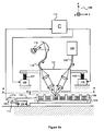
- Figure 1a shows a schematic illustration of an optical measurement instrument comprising an arrangement according to an embodiment of the invention for controlling a measurement head of the optical measurement instrument.
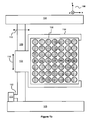
- Figure 1b shows schematic illustration of a view seen downwards from line A-A of figure 1 a.
- the optical measurement instrument comprises first mechanical support elements arranged to support a sample well plate 106, e.g. a microtitration plate. Samples 151, 152, 153, 154, 155, 156, 157 to be measured are stored in sample wells that are built on the sample well plate 106.
- the first mechanical support elements comprise a support rail 103 and guide elements 104 and 105 shown in figure 1b .
- the support rail 103 is supported relative to a body of the optical measurement instrument with the aid of the guide elements 104 and 105 in such a manner that the support rail is movable in the directions of a two-headed arrow 115 shown in figure 1b .
- the first mechanical support elements comprise a sledge 114 capable of receiving the sample well plate 106.
- the sledge is connected with the aid of a part 102 of the first mechanical support elements to the support rail 103 in such a manner that the sledge is capable of sliding along the support rail in the longitudinal direction of the support rail, i.e. the sledge is movable in the directions of a two-headed arrow 116 shown in figure 1 b.
- the samples stored in the sample wells of the sample well plate 106 are movable in the xy-plane defined by a co-ordinate system 190. Due to the fact that the samples are movable in the xy-plane, the samples can be measured in a temporally successive manner so that each sample is in turn the sample that is currently being measured.
- the optical measurement instrument comprises an excitation light source 118 that can be for example a flash lamp such as a xenon flash lamp.
- the excitation light produced by the excitation light source is focused with a concave mirror to a light guide 119 that can be e.g. a fiber bundle.
- the light guide 119 is connected to a measurement head 101 that comprises two channels, one for the excitation beam and another for an emission beam emitted by the sample 153 being measured.
- the measurement head 101 comprises plano-convex lenses arranged to focus the excitation beam to the sample 153 being measured and to collect the emission beam from the sample 153.
- the emission beam is conducted via a light guide 120 to a detector 121 arranged to detect the emission beam emitted by the sample 153 and to produce a detection signal responsive to the detected emission beam.
- the detector can be for example a photodiode or a photomultiplier tube.
- the optical measurement instrument comprises second mechanical support elements arranged to support the measurement head 101 and to allow a distance D from the measurement head to the sample well plate 106 to be changed.
- the second mechanical support elements comprise threaded rods 107 and 108.
- Counterparts 109 and 110 of the threaded rod may comprises, for example, servomotors arranged to move the measurement head 101 in the positive or negative z-direction of the co-ordinate system 190.
- the arrangement according to an embodiment of the invention for controlling the measurement head 101 comprises a controller 111 arranged make the second mechanical support elements 107-110 to move the measurement 101 head towards the sample well plate 106 and, as a response to a situation in which the measurement head touches the sample well plate, to move the measurement head backwards away from the sample well plate with a pre-determined length of movement so as to provide a desired pre-determined distance between the measurement head and the sample well plate.
- the arrangement further comprises a sensor device attached to the first mechanical support elements and arranged to detect a mechanical effect occurring in the first mechanical support elements 102-105 due to force directed by the measurement head 101 to the sample well plate 106 in order to detect the situation in which the measurement head touches the sample well plate.
- the sensor device comprises an overhang 112 attached to the support rail 103 and arranged to be turned as a response to torsion of the support rail due to the force directed by the measurement head to the sample well plate.
- the sensor device comprises a counterpart 113 that is connected to the guide element 105 shown in figure 1b .
- the counterpart 113 is preferably arranged to move in the positive or negative x-direction of the co-ordinate system 190 along with movements of the support rail 103.
- the overhang 112 comprises a contact point that makes an electrical contact with the counterpart 113 as a response to torsion of the support rail 113 due to the force directed by the measurement head to the sample well plate.
- FIG. 1a An arrow 122 shown in figure 1a illustrates the movement of the contact point when the measurement head 101 pushes the sample well plate 106.
- the sensor device shown in figure 1 a comprises actually an electrical contactor the electrical conductivity state of which is arranged to be changed as a response to a situation in which a part of the first mechanical support elements 102-105 is bent due to the force directed by the measurement head to the sample well plate, the mechanical effect to be detected being the bending of the part of the first mechanical support elements.
- the sensor device comprises a pressure force sensor placed between the overhang 112 and the counterpart 113.
- Figure 2 shows a schematic illustration of an optical measurement instrument comprising an arrangement according to an embodiment of the invention for controlling a measurement head of the optical measurement instrument.
- Samples 251, 252, 253, 254, 255, 256, 257 to be measured are stored in sample wells that are built on a sample well plate 206.
- the optical measurement instrument comprises first mechanical support elements arranged to support the sample well plate 206.
- the first mechanical support elements can be similar to those of the optical measurement instrument shown in figures 1a and 1b .
- a measurement head 201 comprises an excitation light source 218 that is a laser source and a detector 221 that is preferably a photomultiplier tube.
- An excitation beam is conducted with a light guide 219 to the sample 253 being excited.
- the detector 221 is arranged to detect an emission beam emitted by the sample 252 being measured and to produce a detection signal responsive to the detected emission beam.
- the optical measurement instrument comprises second mechanical support elements arranged to support the measurement head 201 and to allow a distance D from the measurement head to the sample well plate 206 to be changed.
- the second mechanical support elements can be similar to those of the optical measurement instrument shown in figures 1 a and 1 b.
- the arrangement according to an embodiment of the invention for controlling the measurement head 201 comprises a controller 211 arranged make the second mechanical support elements to move the measurement 201 head towards the sample well plate 206 and, as a response to a situation in which the measurement head touches the sample well plate, to move the measurement head backwards away from the sample well plate with a pre-determined length of movement so as to provide a desired pre-determined distance between the measurement head and the sample well plate.
- the arrangement further comprises a sensor device attached to the first mechanical support elements and arranged to detect a mechanical effect occurring in the first mechanical support elements due to force directed by the measurement head 201 to the sample well plate 206 in order to detect the situation in which the measurement head touches the sample well plate.
- the sensor device comprises a wire strain gauge 217 attached to the first mechanical support elements.
- the wire strain gauge is used for generating a signal responsive to deformation taking place in a part of the first mechanical support elements due to the force directed by the measurement head to the sample well plate.
- the mechanical effect to be detected is therefore a change of mechanical strain occurring in the first mechanical support elements due to the force directed by the measurement head to the sample well plate.
- an optical measurement instrument comprises:
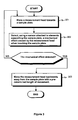
- Figure 3 shows a flow chart of a method according to an embodiment of the invention for controlling a measurement head of an optical measurement instrument that further comprises first mechanical support elements arranged to support a sample well plate to be received, and second mechanical support elements arranged to support the measurement head and to allow a distance from the measurement head to the sample well plate to be changed.
- the method comprises:
- the mechanical effect occurring in the first mechanical support elements is detected with a wire strain gauge attached to the first mechanical support elements, the mechanical effect to be detected being a change of mechanical strain occurring in the first mechanical support elements due to the force directed by the measurement head to the sample well plate.
- the mechanical effect occurring in the first mechanical support elements is detected with an electrical contactor the electrical conductivity state of which is changed as a response to a situation in which a part of the first mechanical support elements is bent due to the force directed by the measurement head to the sample well plate, the mechanical effect to be detected being the bending of the part of the first mechanical support elements.
- the first mechanical support elements comprise a support rail and a sledge capable of receiving the sample well plate and capable of sliding along the support rail in the longitudinal direction of the support rail, and the mechanical effect occurring in the first mechanical support elements is detected with an overhang attached to the support rail and arranged to be turned as a response to torsion of the support rail due to the force directed by the measurement head to the sample well plate, the mechanical effect to be detected being the turning of the overhang.
Landscapes
- Health & Medical Sciences (AREA)
- Chemical & Material Sciences (AREA)
- Biochemistry (AREA)
- Physics & Mathematics (AREA)
- Life Sciences & Earth Sciences (AREA)
- Analytical Chemistry (AREA)
- General Health & Medical Sciences (AREA)
- General Physics & Mathematics (AREA)
- Immunology (AREA)
- Pathology (AREA)
- Chemical Kinetics & Catalysis (AREA)
- Nuclear Medicine, Radiotherapy & Molecular Imaging (AREA)
- Investigating, Analyzing Materials By Fluorescence Or Luminescence (AREA)
- Investigating Or Analysing Materials By Optical Means (AREA)
- Investigating Strength Of Materials By Application Of Mechanical Stress (AREA)
Description
- The invention relates to an arrangement and a method for controlling a measurement head of an optical measurement instrument. An optical measurement can be, for example but not necessarily, an absorption measurement, a photoluminescence measurement, or a chemiluminescence measurement. Furthermore, the invention relates to an optical measurement instrument.
- The work in analytical biochemical laboratories and in clinical laboratories is often based on different tags or labels coupled on macromolecules under inspection. Typical labels used are different radioactive isotopes, enzymes, different fluorescent molecules and e.g. fluorescent chelates of rare earth metals. Detection of enzyme labels can be performed by utilizing its natural biochemical function, i.e. to alter the physical properties of molecules. In enzyme immunoassays colourless substances are catalysed by enzyme to colourful substances or non-fluorescent substances to fluorescent substances.
- The colourful substances can be measured with absorption measurement, i.e. photometric measurement. In the absorption measurement the intensity of filtered and stabilized beam is first measured without any sample and then the sample inside one plate is measured. The absorbance i.e. the absorption values are then calculated.
- The fluorescent substances can be measured with fluorescent measurement that is generally used for measuring quantities of fluorescent label substance in a sample. The most photoluminescence labels are based on molecular photoluminescence process. In this process optical radiation is absorbed by the ground state of a molecule. Due to the absorption of energy the quantum molecule rises into higher excited state. After the fast vibrational relaxation the molecule returns back to its ground state and the excess energy is released as an optical quantum. Due to losses in this process the average absorbed energies are higher than the average emitted energies.
- A further measurement method is chemiluminescence measurement where emission of a substance is measured from a sample without excitation by illumination. Thus a photoluminometer suitable for photoluminescence measurements can also be used as a chemiluminometer.
- Further, there is an analysing method called Amplified Luminescent Proximity Homogeneous Assay or AlphaScreen™. The function of the AlphaScreen™ method is based on the use of small beads that attach to the molecules under study. There are two types of beads that are coated with a material acting either as a donor or acceptor of singlet-state oxygen. The measurement starts, when the liquid sample is illuminated by light with a suitable wavelength e.g. 680 nm. After this, the material in the donor bead converts ambient oxygen into singlet-state oxygen. The single-state molecules have a short lifetime and they can reach only about a 200 nm distance by diffusion in the liquid. If the chemical reaction in question has taken place, both the donor and acceptor beads are bound to the same molecule and so they are sufficiently close to each other. In this case the singlet-state oxygen may reach the acceptor bead where a series of reactions is started. As the last phase of the reaction the coating material in the acceptor beads emits photons in the 500-700 nm range. If the chemical reaction has not taken place the singlet-state oxygen cannot reach the acceptor bead and the emission light is not detected. By measuring the intensity of light it is possible to conclude the efficiency of the chemical reaction.
- An optical measurement instrument suitable for performing some or all of the measurements of the kind described above comprises typically at least one excitation light source for producing excitation beams to one or more samples to be measured at each time. Each excitation light source can be for example a flash lamp or a laser source. An optical path from an excitation light source to a sample may contain for example lenses, fibers, mirrors, dichroic mirrors, optical filters, monochromators and/or other optical elements. The optical measurement instrument further comprises at least one detector for detecting emission beams emitted by the samples to be measured at each time, and for producing detection signals responsive to the detected emission beams. Each detector can be for example a photodiode or a photomultiplier tube. An optical path from the sample to the detector may contain for example lenses, fibers, mirrors, dichroic mirrors, optical filters, monochromators, and/or other optical elements. The optical measurement instrument may further comprise a processing device for producing a measurement result for each sample to be measured on the basis of the detection signal related to that sample. Each sample to be measured is stored in one of a plurality of sample wells that are built on a sample well plate, e.g. a microtitration plate. The optical measurement instrument may comprise, for example, a movable sledge adapted to receive the sample well plate. Due to the fact that the sample well plate is movable, the samples can be measured in a temporally successive manner so that each sample is in turn the sample that is currently being measured and/or excited. In this document an optical module or element that is arranged to direct an excitation beam to a sample and/or to collect emission beam from a sample is called a measurement head. In other words, the measurement head is an optical interface of the optical measurement instrument with respect to a sample to be measured and/or excited.
- In order to provide appropriate optical measurements, the distance from the measurement head to a sample to be measured and/or excited has to be adjusted with a sufficient accuracy. For example in conjunction with many optical measurements, an excitation beam has to be appropriately focused to the sample. The distance between the measurement head and the sample can be adjusted to a desired value for example by first moving the measurement head towards the sample well plate and, after the measurement head has touched the sample well plate, by moving the measurement head backwards away from the sample well plate with a pre-determined length of movement so as to provide the desired distance between the measurement head and the sample well plate. The situation in which the measurement head touches the sample well plate can be detected, for example, with a force sensor attached to the measurement head and arranged detect force directed by the measurement head to the sample well plate. An inconvenience related to a technical solution of the kind described above is that the measurement head can be a changeable module in which case each measurement head has to be provided with an own force sensor or, alternatively, the force sensor has to be moved from one measurement head to another measurement head every time when the measurement head is changed.
- Publication
WO00/04364 - Publication
US2006261829 proposes to the use of physical or optical sensors as displacement sensors when bringing an objective lens near to a sample to be measured. - In accordance with a first aspect of the invention, there is provided a new arrangement for controlling a measurement head of an optical measurement instrument, the measurement head being an optical interface of the optical measurement instrument with respect to a sample to be measured and/or excited, and the optical measurement instrument further comprising first mechanical support elements arranged to support a sample well plate to be received and second me-chanical support elements arranged to support the measurement head and to allow a distance from the measurement head to the sample well plate to be changed. The arrangement according to the invention comprises:
- a controller arranged make, in a situation in which the sample well plate is placed on the first mechanical support elements, the second mechanical support elements to move the measurement head towards the sample well plate and, as a response to a situation in which the measurement head touches the sample well plate, to move the measurement head backwards away from the sample well plate with a pre-determined length of movement so as to provide a pre-determined distance between the measurement head and the sample well plate, and
- a sensor device arranged to detect, in the situation in which the sample well plate is placed on the first mechanical support elements, the situation in which the measurement head touches the sample well plate,
- The situation in which the measurement head touches the sample well plate can be detected without a need to provide the measurement head with a sensor. This is advantageous because the measurement head can be a changeable module of the optical measurement instrument and thus, using the arrangement according to the invention, there is no need to provide each measurement head with an own sensor or to move a force sensor from one measurement head to another measurement head every time when the measurement head is changed.
- In accordance with a second aspect of the invention, there is provided a new optical measurement instrument comprising:
- a measurement head being an optical interface of the optical measurement instrument with respect to a sample to be measured and/or excited,
- first mechanical support elements arranged to support a sample well plate to be received,
- second mechanical support elements arranged to support the measurement head and to allow a distance from the measurement head to the sample well plate to be changed,
- a controller arranged make, in a situation in which the sample well plate is placed on the first mechanical support elements, the second mechanical support elements to move the measurement head towards the sample well plate and, as a response to a situation in which the measurement head touches the sample well plate, to move the measurement head backwards away from the sample well plate with a pre-determined length of movement so as to provide a pre-determined distance between the measurement head and the sample well plate, and
- a sensor device arranged to detect, in the situation in which the sample well plate is placed on the first mechanical support elements, the situation in which the measurement head touches the sample well plate,
- In accordance with a third aspect of the invention, there is provided a new method for controlling a measurement head of an optical measurement instrument, the measurement head being an optical interface of the optical measurement instrument with respect to a sample to be measured and/or excited, and the optical measurement instrument further comprising first mechanical support elements arranged to support a sample well plate to be received, and second mechanical support elements arranged to support the measurement head and to allow a distance from the measurement head to the sample well plate to be changed. The method according to the invention comprises:
- moving the measurement head towards the sample well plate placed on the first mechanical support elements,
- detecting, with a sensor device attached to the first mechanical support elements, a mechanical effect occurring in the first mechanical support elements in order to detect a situation in which the measurement head touches the sample well plate, and
- as a response to the situation in which the measurement head touches the sample well plate, moving the measurement head backwards away from the sample well plate with a pre-determined length of movement so as to provide a pre-determined distance between the measurement head and the sample well plate.
- A number of exemplifying embodiments of the invention are described in accompanied dependent claims.
- Various exemplifying embodiments of the invention both as to constructions and to methods of operation, together with additional objects and advantages thereof, will be best understood from the following description of specific exemplifying embodiments when read in connection with the accompanying drawings.
- The verb "to comprise" is used in this document as an open limitation that does not exclude the existence of also unrecited features. The features recited in depending claims are mutually freely combinable unless otherwise explicitly stated.
- The exemplifying embodiments of the invention and their advantages are explained in greater detail below in the sense of examples and with reference to the accompanying drawings, in which:
-
figure 1a shows a schematic illustration of an optical measurement instrument comprising an arrangement according to an embodiment of the invention for controlling a measurement head of the optical measurement instrument, -
figure 1b shows a schematic illustration of a view seen downwards from line A-A offigure 1a , -
figure 2 shows a schematic illustration of an optical measurement instrument comprising an arrangement according to an embodiment of the invention for controlling a measurement head of the optical measurement instrument, and -
figure 3 shows a flow chart of a method according to an embodiment of the invention for controlling a measurement head of an optical measurement instrument. -
Figure 1a shows a schematic illustration of an optical measurement instrument comprising an arrangement according to an embodiment of the invention for controlling a measurement head of the optical measurement instrument.Figure 1b shows schematic illustration of a view seen downwards from line A-A offigure 1 a. The optical measurement instrument comprises first mechanical support elements arranged to support asample well plate 106, e.g. a microtitration plate.Samples sample well plate 106. The first mechanical support elements comprise asupport rail 103 and guideelements figure 1b . Thesupport rail 103 is supported relative to a body of the optical measurement instrument with the aid of theguide elements arrow 115 shown infigure 1b . The first mechanical support elements comprise asledge 114 capable of receiving thesample well plate 106. The sledge is connected with the aid of apart 102 of the first mechanical support elements to thesupport rail 103 in such a manner that the sledge is capable of sliding along the support rail in the longitudinal direction of the support rail, i.e. the sledge is movable in the directions of a two-headedarrow 116 shown infigure 1 b. Hence, the samples stored in the sample wells of thesample well plate 106 are movable in the xy-plane defined by a co-ordinatesystem 190. Due to the fact that the samples are movable in the xy-plane, the samples can be measured in a temporally successive manner so that each sample is in turn the sample that is currently being measured. - The optical measurement instrument comprises an
excitation light source 118 that can be for example a flash lamp such as a xenon flash lamp. The excitation light produced by the excitation light source is focused with a concave mirror to alight guide 119 that can be e.g. a fiber bundle. Thelight guide 119 is connected to ameasurement head 101 that comprises two channels, one for the excitation beam and another for an emission beam emitted by thesample 153 being measured. Themeasurement head 101 comprises plano-convex lenses arranged to focus the excitation beam to thesample 153 being measured and to collect the emission beam from thesample 153. The emission beam is conducted via alight guide 120 to adetector 121 arranged to detect the emission beam emitted by thesample 153 and to produce a detection signal responsive to the detected emission beam. The detector can be for example a photodiode or a photomultiplier tube. - The optical measurement instrument comprises second mechanical support elements arranged to support the
measurement head 101 and to allow a distance D from the measurement head to thesample well plate 106 to be changed. The second mechanical support elements comprise threadedrods Counterparts measurement head 101 in the positive or negative z-direction of the co-ordinatesystem 190. - The arrangement according to an embodiment of the invention for controlling the
measurement head 101 comprises acontroller 111 arranged make the second mechanical support elements 107-110 to move themeasurement 101 head towards thesample well plate 106 and, as a response to a situation in which the measurement head touches the sample well plate, to move the measurement head backwards away from the sample well plate with a pre-determined length of movement so as to provide a desired pre-determined distance between the measurement head and the sample well plate. The arrangement further comprises a sensor device attached to the first mechanical support elements and arranged to detect a mechanical effect occurring in the first mechanical support elements 102-105 due to force directed by themeasurement head 101 to thesample well plate 106 in order to detect the situation in which the measurement head touches the sample well plate. - The sensor device comprises an
overhang 112 attached to thesupport rail 103 and arranged to be turned as a response to torsion of the support rail due to the force directed by the measurement head to the sample well plate. The sensor device comprises acounterpart 113 that is connected to theguide element 105 shown infigure 1b . Thecounterpart 113 is preferably arranged to move in the positive or negative x-direction of the co-ordinatesystem 190 along with movements of thesupport rail 103. Theoverhang 112 comprises a contact point that makes an electrical contact with thecounterpart 113 as a response to torsion of thesupport rail 113 due to the force directed by the measurement head to the sample well plate. Anarrow 122 shown infigure 1a illustrates the movement of the contact point when themeasurement head 101 pushes thesample well plate 106. Hence, the sensor device shown infigure 1 a comprises actually an electrical contactor the electrical conductivity state of which is arranged to be changed as a response to a situation in which a part of the first mechanical support elements 102-105 is bent due to the force directed by the measurement head to the sample well plate, the mechanical effect to be detected being the bending of the part of the first mechanical support elements. It is also possible that the sensor device comprises a pressure force sensor placed between theoverhang 112 and thecounterpart 113.Figure 2 shows a schematic illustration of an optical measurement instrument comprising an arrangement according to an embodiment of the invention for controlling a measurement head of the optical measurement instrument.Samples sample well plate 206. The optical measurement instrument comprises first mechanical support elements arranged to support thesample well plate 206. The first mechanical support elements can be similar to those of the optical measurement instrument shown infigures 1a and1b . - A
measurement head 201 comprises anexcitation light source 218 that is a laser source and adetector 221 that is preferably a photomultiplier tube. An excitation beam is conducted with alight guide 219 to thesample 253 being excited. Thedetector 221 is arranged to detect an emission beam emitted by thesample 252 being measured and to produce a detection signal responsive to the detected emission beam. - The optical measurement instrument comprises second mechanical support elements arranged to support the
measurement head 201 and to allow a distance D from the measurement head to thesample well plate 206 to be changed. The second mechanical support elements can be similar to those of the optical measurement instrument shown infigures 1 a and 1 b. - The arrangement according to an embodiment of the invention for controlling the
measurement head 201 comprises acontroller 211 arranged make the second mechanical support elements to move themeasurement 201 head towards thesample well plate 206 and, as a response to a situation in which the measurement head touches the sample well plate, to move the measurement head backwards away from the sample well plate with a pre-determined length of movement so as to provide a desired pre-determined distance between the measurement head and the sample well plate. The arrangement further comprises a sensor device attached to the first mechanical support elements and arranged to detect a mechanical effect occurring in the first mechanical support elements due to force directed by themeasurement head 201 to thesample well plate 206 in order to detect the situation in which the measurement head touches the sample well plate. The sensor device comprises awire strain gauge 217 attached to the first mechanical support elements. The wire strain gauge is used for generating a signal responsive to deformation taking place in a part of the first mechanical support elements due to the force directed by the measurement head to the sample well plate. The mechanical effect to be detected is therefore a change of mechanical strain occurring in the first mechanical support elements due to the force directed by the measurement head to the sample well plate. - Referring to
figures 1 and2 , an optical measurement instrument according to an embodiment of the invention comprises: - a
measurement head - first mechanical support elements 102-105 arranged to support a
sample well plate 106, - second mechanical support elements 107-110 arranged to support the measurement head and to allow a distance D from the measurement head to the sample well plate to be changed,
- a
controller - a
sensor device -
Figure 3 shows a flow chart of a method according to an embodiment of the invention for controlling a measurement head of an optical measurement instrument that further comprises first mechanical support elements arranged to support a sample well plate to be received, and second mechanical support elements arranged to support the measurement head and to allow a distance from the measurement head to the sample well plate to be changed. The method comprises: - moving in a
phase 301 the measurement head towards the sample well plate, - detecting in
phase 302 with the aid of a sensor device attached to the first mechanical support elements a mechanical effect occurring in the first mechanical support elements in order to detect a situation in which the measurement head touches the sample well plate, and - as a response to the situation in which the measurement head touches the sample well plate, moving in a
phase 303 the measurement head backwards away from the sample well plate with a pre-determined length of movement so as to provide a desired pre-determined distance between the measurement head and the sample well plate. - In a method according to an embodiment of the invention, the mechanical effect occurring in the first mechanical support elements is detected with a wire strain gauge attached to the first mechanical support elements, the mechanical effect to be detected being a change of mechanical strain occurring in the first mechanical support elements due to the force directed by the measurement head to the sample well plate.
- In a method according to an embodiment of the invention, the mechanical effect occurring in the first mechanical support elements is detected with an electrical contactor the electrical conductivity state of which is changed as a response to a situation in which a part of the first mechanical support elements is bent due to the force directed by the measurement head to the sample well plate, the mechanical effect to be detected being the bending of the part of the first mechanical support elements.
- In a method according to an embodiment of the invention, the first mechanical support elements comprise a support rail and a sledge capable of receiving the sample well plate and capable of sliding along the support rail in the longitudinal direction of the support rail, and the mechanical effect occurring in the first mechanical support elements is detected with an overhang attached to the support rail and arranged to be turned as a response to torsion of the support rail due to the force directed by the measurement head to the sample well plate, the mechanical effect to be detected being the turning of the overhang.
- The specific examples provided in the description given above should not be construed as limiting. Therefore, the invention is not limited merely to the embodiments described above.
Claims (9)
- An arrangement for controlling a measurement head (101, 201) of an optical measurement instrument, the optical measurement instrument comprising first mechanical support elements (102-105) arranged to support a sample well plate (106, 206) to be received, and second mechanical support elements (107-110) arranged to support the measurement head and to allow a distance (D) from the measurement head to the sample well plate to be changed, and the arrangement comprising:- a controller (111, 211) arranged to make, in a situation in which the sample well plate is placed on the first mechanical support elements, the second mechanical support elements to move the measurement head towards the sample well plate and, as a response to a situation in which the measurement head touches the sample well plate, to move the measurement head backwards away from the sample well plate with a pre-determined length of movement so as to provide a pre-determined distance between the measurement head and the sample well plate, and- a sensor device (112,113,217) arranged to detect, in the situation in which the sample well plate is placed on the first mechanical support elements, the situation in which the measurement head touches the sample well plate,characterized in that the sensor device is attached to the first mechanical support elements and arranged to detect, in the situation in which the sample well plate is placed on the first mechanical support elements, a mechanical effect occurring in the first mechanical support elements due to force directed by the measurement head to the sample well plate.
- An arrangement according to claim 1, wherein the sensor device comprises a wire strain gauge (217) attached to the first mechanical support elements, the mechanical effect to be detected being a change of mechanical strain occurring in the first mechanical support elements due to the force directed by the measurement head to the sample well plate.
- An arrangement according to claim 1, wherein the sensor device comprises an electrical contactor (112, 113) the electrical conductivity state of which is arranged to be changed as a response to a situation in which a part of the first mechanical support elements is bent due to the force directed by the measurement head to the sample well plate, the mechanical effect to be detected being bending of the part of the first mechanical support elements.
- An arrangement according to claim 3, wherein the first mechanical support elements comprise a support rail (103) and a sledge (114) capable of receiving the sample well plate and capable of sliding along the support rail in the longitudinal direction of the support rail, the sensor device comprising an overhang (112) attached to the support rail and arranged to be turned as a response to torsion of the support rail due to the force directed by the measurement head to the sample well plate, the mechanical effect to be detected being turning of the overhang.
- An optical measurement instrument comprising:- a measurement head (101, 201),- first mechanical support elements (102-105) arranged to support a sample well plate (106, 206) to be received, and- second mechanical support elements (107-110) arranged to support the measurement head and to allow, in a situation in which the sample well plate is placed on the first mechanical support elements, a distance from the measurement head to the sample well plate to be changed,characterized in that the optical measurement instrument further comprises an arrangement according to any of the preceding claims for controlling, in the situation in which the sample well plate is placed on the first mechanical support elements, the position of the measurement head relative to the sample well plate.
- A method for controlling a measurement head of an optical measurement instrument, and the optical measurement instrument comprising first mechanical support elements arranged to support a sample well plate to be received and second mechanical support elements arranged to support the measurement head and to allow a distance from the measurement head to the sample well plate to be changed, the method comprising:- moving (301) the measurement head towards the sample well plate placed on the first mechanical support elements,- detecting (302) a situation in which the measurement head touches the sample well plate, and- as a response to the situation in which the measurement head touches the sample well plate, moving (303) the measurement head backwards away from the sample well plate with a pre-determined length of movement so as to provide a pre-determined distance between the measurement head and the sample well plate,characterized in that the situation in which the measurement head touches the sample well plate is detected by detecting (301), with a sensor device attached to the first mechanical support elements, a mechanical effect occurring in the first mechanical support elements due to force directed by the measurement head to the sample well plate.
- A method according to claim 6, wherein the mechanical effect occurring in the first mechanical support elements is detected with a wire strain gauge attached to the first mechanical support elements, the mechanical effect to be detected being a change of mechanical strain occurring in the first mechanical support elements due to the force directed by the measurement head to the sample well plate.
- A method according to claim 6, wherein the mechanical effect occurring in the first mechanical support elements is detected with an electrical contactor the electrical conductivity state of which is changed as a response to a situation in which a part of the first mechanical support elements is bent due to the force directed by the measurement head to the sample well plate, the mechanical effect to be detected being bending of the part of the first mechanical support elements.
- A method according to claim 6 or 8, wherein the first mechanical support elements comprise a support rail and a sledge capable of receiving the sample well plate and capable of sliding along the support rail in the longitudinal direction of the support rail, and the mechanical effect occurring in the first mechanical support elements is detected with an overhang attached to the support rail and arranged to be turned as a response to torsion of the support rail due to the force directed by the measurement head to the sample well plate, the mechanical effect to be detected being turning of the overhang.
Applications Claiming Priority (3)
| Application Number | Priority Date | Filing Date | Title |
|---|---|---|---|
| FI20095064A FI20095064A0 (en) | 2009-01-26 | 2009-01-26 | Apparatus and method for controlling the measuring head of an optical measuring instrument |
| US14955709P | 2009-02-03 | 2009-02-03 | |
| PCT/FI2010/050022 WO2010084244A1 (en) | 2009-01-26 | 2010-01-18 | An arrangement and a method for controlling a measurement head of an optical measurement instrument |
Publications (2)
| Publication Number | Publication Date |
|---|---|
| EP2382476A1 EP2382476A1 (en) | 2011-11-02 |
| EP2382476B1 true EP2382476B1 (en) | 2012-11-28 |
Family
ID=40329519
Family Applications (1)
| Application Number | Title | Priority Date | Filing Date |
|---|---|---|---|
| EP10702718A Active EP2382476B1 (en) | 2009-01-26 | 2010-01-18 | An arrangement and a method for controlling a measurement head of an optical measurement instrument |
Country Status (6)
| Country | Link |
|---|---|
| US (1) | US8542349B2 (en) |
| EP (1) | EP2382476B1 (en) |
| CN (1) | CN102292643B (en) |
| CA (1) | CA2748731C (en) |
| FI (1) | FI20095064A0 (en) |
| WO (1) | WO2010084244A1 (en) |
Cited By (1)
| Publication number | Priority date | Publication date | Assignee | Title |
|---|---|---|---|---|
| CN104777136A (en) * | 2015-03-25 | 2015-07-15 | 深圳市前海安测信息技术有限公司 | SPR technology based biomarker detection method and system |
Families Citing this family (10)
| Publication number | Priority date | Publication date | Assignee | Title |
|---|---|---|---|---|
| FI20095063A0 (en) * | 2009-01-26 | 2009-01-26 | Wallac Oy | Optical measuring instrument |
| FI20115483A0 (en) * | 2011-05-19 | 2011-05-19 | Wallac Oy | Measuring Instruments |
| TW201516533A (en) * | 2013-10-21 | 2015-05-01 | Hon Hai Prec Ind Co Ltd | Backlight module |
| CN105899294B (en) * | 2013-11-19 | 2019-08-16 | Idea机器显影设计及生产有限公司 | Multiwell plate and method of use thereof |
| CN107209110B (en) * | 2014-08-28 | 2020-01-17 | 辛格科技公司 | High-throughput biochemical screening |
| US11110450B2 (en) * | 2016-01-29 | 2021-09-07 | Hewlett-Packard Development Company, L.P. | Sample-reagent mixture thermal cycling |
| SG11202000964UA (en) * | 2017-08-15 | 2020-02-27 | Omniome Inc | Scanning apparatus and methods useful for detection of chemical and biological analytes |
| JP7372311B2 (en) * | 2018-04-17 | 2023-10-31 | トーテムス・ポジション・ソシエテ・ア・レスポンサビリテ・リミテ | Part positioning device and positioning method |
| DE102018212489A1 (en) | 2018-07-26 | 2020-01-30 | Implen GmbH | Device for light spectroscopic analysis |
| CN113613787B (en) * | 2019-02-20 | 2023-06-13 | 加利福尼亚太平洋生物科学股份有限公司 | Scanning device and method for detecting chemical and biological analytes |
Family Cites Families (10)
| Publication number | Priority date | Publication date | Assignee | Title |
|---|---|---|---|---|
| EP0030148A1 (en) | 1979-11-28 | 1981-06-10 | Portalab Instruments Limited | Portable photometer |
| WO2000004364A2 (en) | 1998-07-15 | 2000-01-27 | Ljl Biosystems, Inc. | Evanescent field illumination devices and methods |
| FI982005A7 (en) | 1998-09-17 | 2000-03-18 | Wallac Oy | Sample imaging device |
| JP2002156383A (en) | 2000-11-21 | 2002-05-31 | Fuji Photo Film Co Ltd | Height position adjusting device, optical system height position adjusting device and data-generating device using optical system height position adjusting device |
| DE10121732A1 (en) | 2001-05-04 | 2002-11-07 | Leica Microsystems | Microscope and method for operating a microscope |
| US7123035B2 (en) | 2002-04-10 | 2006-10-17 | Credence Systems Corporation | Optics landing system and method therefor |
| US20040096368A1 (en) | 2002-06-28 | 2004-05-20 | Igen International, Inc. | Assay systems and components |
| JP2005106790A (en) * | 2003-01-09 | 2005-04-21 | Univ Kanazawa | Scanning probe microscope and molecular structure change observation method |
| WO2007113895A1 (en) | 2006-04-03 | 2007-10-11 | Shimadzu Corporation | Optical measurement instrument for trace liquid sample |
| CN2916659Y (en) * | 2006-06-19 | 2007-06-27 | 中国科学院上海光学精密机械研究所 | Modular Scanning Probe Microscope |
-
2009
- 2009-01-26 FI FI20095064A patent/FI20095064A0/en not_active Application Discontinuation
-
2010
- 2010-01-18 WO PCT/FI2010/050022 patent/WO2010084244A1/en not_active Ceased
- 2010-01-18 CN CN201080005118.3A patent/CN102292643B/en active Active
- 2010-01-18 EP EP10702718A patent/EP2382476B1/en active Active
- 2010-01-18 CA CA2748731A patent/CA2748731C/en active Active
- 2010-01-18 US US13/145,652 patent/US8542349B2/en active Active
Cited By (2)
| Publication number | Priority date | Publication date | Assignee | Title |
|---|---|---|---|---|
| CN104777136A (en) * | 2015-03-25 | 2015-07-15 | 深圳市前海安测信息技术有限公司 | SPR technology based biomarker detection method and system |
| CN104777136B (en) * | 2015-03-25 | 2018-06-19 | 深圳市贝沃德克生物技术研究院有限公司 | Biological marker object detecting method and system based on surface plasma resonance technology |
Also Published As
| Publication number | Publication date |
|---|---|
| CA2748731A1 (en) | 2010-07-29 |
| CN102292643B (en) | 2014-03-05 |
| CA2748731C (en) | 2017-06-27 |
| US20120002190A1 (en) | 2012-01-05 |
| WO2010084244A1 (en) | 2010-07-29 |
| FI20095064A0 (en) | 2009-01-26 |
| EP2382476A1 (en) | 2011-11-02 |
| CN102292643A (en) | 2011-12-21 |
| US8542349B2 (en) | 2013-09-24 |
Similar Documents
| Publication | Publication Date | Title |
|---|---|---|
| US8542349B2 (en) | Arrangement and a method for controlling a measurement head of an optical measurement instrument | |
| Dallas et al. | Light at the end of the tunnel: recent analytical applications of liquid-core waveguides | |
| US20020179849A1 (en) | Multiplexed fluorescent detection in microfluidic devices | |
| US20090279093A1 (en) | Integrated biosensing device having photo detector | |
| RU2013117936A (en) | SYSTEMS AND METHODS FOR EVALUATING CHARACTERISTICS OF BIOMOLECULES | |
| EP2382477B1 (en) | A body module for an optical measurement instrument | |
| EP2382455B1 (en) | Instrumentation and method for optical measurement of samples | |
| EP2382724B1 (en) | An optical measurement instrument with data transmission | |
| CN103196878A (en) | Portable fluorescence detector | |
| JP2025169346A (en) | Capillary array window holder related systems and methods | |
| JP2008512666A (en) | Instruments and methods compatible with optical measurements of amplified luminescent proximity homogeneity assay (Amplified Luminescent Proximity Homogenous Assay) | |
| ES2950088T3 (en) | Scanner photometer head and associated method | |
| JP2001337083A (en) | Optical system for micro chemical analysis system | |
| EP3325602B1 (en) | Wavelength scanning apparatus and method of use thereof | |
| US8896820B2 (en) | Optical measurement instrument | |
| CN1431320A (en) | Low density biochip detection method and its system | |
| TWI336399B (en) | Multi-wavelength fluorescence detecting method of a microchip system | |
| CN102419316A (en) | Micro-beam multi-path parallel surface plasma resonance detection system | |
| JP2004325396A (en) | Method for evaluating sensitivity of signal reader |
Legal Events
| Date | Code | Title | Description |
|---|---|---|---|
| PUAI | Public reference made under article 153(3) epc to a published international application that has entered the european phase |
Free format text: ORIGINAL CODE: 0009012 |
|
| 17P | Request for examination filed |
Effective date: 20110616 |
|
| AK | Designated contracting states |
Kind code of ref document: A1 Designated state(s): AT BE BG CH CY CZ DE DK EE ES FI FR GB GR HR HU IE IS IT LI LT LU LV MC MK MT NL NO PL PT RO SE SI SK SM TR |
|
| REG | Reference to a national code |
Ref country code: DE Ref legal event code: R079 Ref document number: 602010003852 Country of ref document: DE Free format text: PREVIOUS MAIN CLASS: G01N0035000000 Ipc: G01N0035020000 |
|
| DAX | Request for extension of the european patent (deleted) | ||
| GRAP | Despatch of communication of intention to grant a patent |
Free format text: ORIGINAL CODE: EPIDOSNIGR1 |
|
| RIC1 | Information provided on ipc code assigned before grant |
Ipc: G01N 35/02 20060101AFI20120413BHEP Ipc: G01N 21/64 20060101ALI20120413BHEP |
|
| GRAS | Grant fee paid |
Free format text: ORIGINAL CODE: EPIDOSNIGR3 |
|
| GRAA | (expected) grant |
Free format text: ORIGINAL CODE: 0009210 |
|
| RAP1 | Party data changed (applicant data changed or rights of an application transferred) |
Owner name: PERKINELMER SINGAPORE PTE. LTD. |
|
| AK | Designated contracting states |
Kind code of ref document: B1 Designated state(s): AT BE BG CH CY CZ DE DK EE ES FI FR GB GR HR HU IE IS IT LI LT LU LV MC MK MT NL NO PL PT RO SE SI SK SM TR |
|
| REG | Reference to a national code |
Ref country code: GB Ref legal event code: FG4D |
|
| REG | Reference to a national code |
Ref country code: CH Ref legal event code: EP |
|
| REG | Reference to a national code |
Ref country code: AT Ref legal event code: REF Ref document number: 586435 Country of ref document: AT Kind code of ref document: T Effective date: 20121215 |
|
| REG | Reference to a national code |
Ref country code: IE Ref legal event code: FG4D |
|
| REG | Reference to a national code |
Ref country code: DE Ref legal event code: R096 Ref document number: 602010003852 Country of ref document: DE Effective date: 20130124 |
|
| REG | Reference to a national code |
Ref country code: AT Ref legal event code: MK05 Ref document number: 586435 Country of ref document: AT Kind code of ref document: T Effective date: 20121128 |
|
| REG | Reference to a national code |
Ref country code: NL Ref legal event code: VDEP Effective date: 20121128 |
|
| REG | Reference to a national code |
Ref country code: LT Ref legal event code: MG4D |
|
| PG25 | Lapsed in a contracting state [announced via postgrant information from national office to epo] |
Ref country code: SE Free format text: LAPSE BECAUSE OF FAILURE TO SUBMIT A TRANSLATION OF THE DESCRIPTION OR TO PAY THE FEE WITHIN THE PRESCRIBED TIME-LIMIT Effective date: 20121128 Ref country code: LT Free format text: LAPSE BECAUSE OF FAILURE TO SUBMIT A TRANSLATION OF THE DESCRIPTION OR TO PAY THE FEE WITHIN THE PRESCRIBED TIME-LIMIT Effective date: 20121128 Ref country code: ES Free format text: LAPSE BECAUSE OF FAILURE TO SUBMIT A TRANSLATION OF THE DESCRIPTION OR TO PAY THE FEE WITHIN THE PRESCRIBED TIME-LIMIT Effective date: 20130311 Ref country code: NO Free format text: LAPSE BECAUSE OF FAILURE TO SUBMIT A TRANSLATION OF THE DESCRIPTION OR TO PAY THE FEE WITHIN THE PRESCRIBED TIME-LIMIT Effective date: 20130228 |
|
| PG25 | Lapsed in a contracting state [announced via postgrant information from national office to epo] |
Ref country code: PT Free format text: LAPSE BECAUSE OF FAILURE TO SUBMIT A TRANSLATION OF THE DESCRIPTION OR TO PAY THE FEE WITHIN THE PRESCRIBED TIME-LIMIT Effective date: 20130328 Ref country code: BE Free format text: LAPSE BECAUSE OF FAILURE TO SUBMIT A TRANSLATION OF THE DESCRIPTION OR TO PAY THE FEE WITHIN THE PRESCRIBED TIME-LIMIT Effective date: 20121128 Ref country code: LV Free format text: LAPSE BECAUSE OF FAILURE TO SUBMIT A TRANSLATION OF THE DESCRIPTION OR TO PAY THE FEE WITHIN THE PRESCRIBED TIME-LIMIT Effective date: 20121128 Ref country code: GR Free format text: LAPSE BECAUSE OF FAILURE TO SUBMIT A TRANSLATION OF THE DESCRIPTION OR TO PAY THE FEE WITHIN THE PRESCRIBED TIME-LIMIT Effective date: 20130301 Ref country code: PL Free format text: LAPSE BECAUSE OF FAILURE TO SUBMIT A TRANSLATION OF THE DESCRIPTION OR TO PAY THE FEE WITHIN THE PRESCRIBED TIME-LIMIT Effective date: 20121128 Ref country code: SI Free format text: LAPSE BECAUSE OF FAILURE TO SUBMIT A TRANSLATION OF THE DESCRIPTION OR TO PAY THE FEE WITHIN THE PRESCRIBED TIME-LIMIT Effective date: 20121128 |
|
| PG25 | Lapsed in a contracting state [announced via postgrant information from national office to epo] |
Ref country code: AT Free format text: LAPSE BECAUSE OF FAILURE TO SUBMIT A TRANSLATION OF THE DESCRIPTION OR TO PAY THE FEE WITHIN THE PRESCRIBED TIME-LIMIT Effective date: 20121128 |
|
| PG25 | Lapsed in a contracting state [announced via postgrant information from national office to epo] |
Ref country code: DK Free format text: LAPSE BECAUSE OF FAILURE TO SUBMIT A TRANSLATION OF THE DESCRIPTION OR TO PAY THE FEE WITHIN THE PRESCRIBED TIME-LIMIT Effective date: 20121128 Ref country code: SK Free format text: LAPSE BECAUSE OF FAILURE TO SUBMIT A TRANSLATION OF THE DESCRIPTION OR TO PAY THE FEE WITHIN THE PRESCRIBED TIME-LIMIT Effective date: 20121128 Ref country code: BG Free format text: LAPSE BECAUSE OF FAILURE TO SUBMIT A TRANSLATION OF THE DESCRIPTION OR TO PAY THE FEE WITHIN THE PRESCRIBED TIME-LIMIT Effective date: 20130228 Ref country code: CZ Free format text: LAPSE BECAUSE OF FAILURE TO SUBMIT A TRANSLATION OF THE DESCRIPTION OR TO PAY THE FEE WITHIN THE PRESCRIBED TIME-LIMIT Effective date: 20121128 Ref country code: EE Free format text: LAPSE BECAUSE OF FAILURE TO SUBMIT A TRANSLATION OF THE DESCRIPTION OR TO PAY THE FEE WITHIN THE PRESCRIBED TIME-LIMIT Effective date: 20121128 |
|
| PG25 | Lapsed in a contracting state [announced via postgrant information from national office to epo] |
Ref country code: RO Free format text: LAPSE BECAUSE OF FAILURE TO SUBMIT A TRANSLATION OF THE DESCRIPTION OR TO PAY THE FEE WITHIN THE PRESCRIBED TIME-LIMIT Effective date: 20121128 Ref country code: MC Free format text: LAPSE BECAUSE OF NON-PAYMENT OF DUE FEES Effective date: 20130131 Ref country code: NL Free format text: LAPSE BECAUSE OF FAILURE TO SUBMIT A TRANSLATION OF THE DESCRIPTION OR TO PAY THE FEE WITHIN THE PRESCRIBED TIME-LIMIT Effective date: 20121128 Ref country code: IT Free format text: LAPSE BECAUSE OF FAILURE TO SUBMIT A TRANSLATION OF THE DESCRIPTION OR TO PAY THE FEE WITHIN THE PRESCRIBED TIME-LIMIT Effective date: 20121128 |
|
| PLBE | No opposition filed within time limit |
Free format text: ORIGINAL CODE: 0009261 |
|
| STAA | Information on the status of an ep patent application or granted ep patent |
Free format text: STATUS: NO OPPOSITION FILED WITHIN TIME LIMIT |
|
| REG | Reference to a national code |
Ref country code: IE Ref legal event code: MM4A |
|
| REG | Reference to a national code |
Ref country code: FR Ref legal event code: ST Effective date: 20130930 |
|
| 26N | No opposition filed |
Effective date: 20130829 |
|
| PG25 | Lapsed in a contracting state [announced via postgrant information from national office to epo] |
Ref country code: CY Free format text: LAPSE BECAUSE OF FAILURE TO SUBMIT A TRANSLATION OF THE DESCRIPTION OR TO PAY THE FEE WITHIN THE PRESCRIBED TIME-LIMIT Effective date: 20121128 Ref country code: FR Free format text: LAPSE BECAUSE OF NON-PAYMENT OF DUE FEES Effective date: 20130131 |
|
| REG | Reference to a national code |
Ref country code: DE Ref legal event code: R097 Ref document number: 602010003852 Country of ref document: DE Effective date: 20130829 |
|
| PG25 | Lapsed in a contracting state [announced via postgrant information from national office to epo] |
Ref country code: IE Free format text: LAPSE BECAUSE OF NON-PAYMENT OF DUE FEES Effective date: 20130118 Ref country code: HR Free format text: LAPSE BECAUSE OF FAILURE TO SUBMIT A TRANSLATION OF THE DESCRIPTION OR TO PAY THE FEE WITHIN THE PRESCRIBED TIME-LIMIT Effective date: 20130731 |
|
| PG25 | Lapsed in a contracting state [announced via postgrant information from national office to epo] |
Ref country code: MT Free format text: LAPSE BECAUSE OF FAILURE TO SUBMIT A TRANSLATION OF THE DESCRIPTION OR TO PAY THE FEE WITHIN THE PRESCRIBED TIME-LIMIT Effective date: 20121128 |
|
| REG | Reference to a national code |
Ref country code: CH Ref legal event code: PL |
|
| PG25 | Lapsed in a contracting state [announced via postgrant information from national office to epo] |
Ref country code: LI Free format text: LAPSE BECAUSE OF NON-PAYMENT OF DUE FEES Effective date: 20140131 Ref country code: CH Free format text: LAPSE BECAUSE OF NON-PAYMENT OF DUE FEES Effective date: 20140131 |
|
| PG25 | Lapsed in a contracting state [announced via postgrant information from national office to epo] |
Ref country code: SM Free format text: LAPSE BECAUSE OF FAILURE TO SUBMIT A TRANSLATION OF THE DESCRIPTION OR TO PAY THE FEE WITHIN THE PRESCRIBED TIME-LIMIT Effective date: 20121128 |
|
| PG25 | Lapsed in a contracting state [announced via postgrant information from national office to epo] |
Ref country code: TR Free format text: LAPSE BECAUSE OF FAILURE TO SUBMIT A TRANSLATION OF THE DESCRIPTION OR TO PAY THE FEE WITHIN THE PRESCRIBED TIME-LIMIT Effective date: 20121128 |
|
| PG25 | Lapsed in a contracting state [announced via postgrant information from national office to epo] |
Ref country code: HU Free format text: LAPSE BECAUSE OF FAILURE TO SUBMIT A TRANSLATION OF THE DESCRIPTION OR TO PAY THE FEE WITHIN THE PRESCRIBED TIME-LIMIT; INVALID AB INITIO Effective date: 20100118 Ref country code: MK Free format text: LAPSE BECAUSE OF FAILURE TO SUBMIT A TRANSLATION OF THE DESCRIPTION OR TO PAY THE FEE WITHIN THE PRESCRIBED TIME-LIMIT Effective date: 20121128 Ref country code: LU Free format text: LAPSE BECAUSE OF NON-PAYMENT OF DUE FEES Effective date: 20130118 |
|
| PG25 | Lapsed in a contracting state [announced via postgrant information from national office to epo] |
Ref country code: IS Free format text: LAPSE BECAUSE OF FAILURE TO SUBMIT A TRANSLATION OF THE DESCRIPTION OR TO PAY THE FEE WITHIN THE PRESCRIBED TIME-LIMIT Effective date: 20121128 |
|
| P01 | Opt-out of the competence of the unified patent court (upc) registered |
Effective date: 20230526 |
|
| PGFP | Annual fee paid to national office [announced via postgrant information from national office to epo] |
Ref country code: GB Payment date: 20260127 Year of fee payment: 17 |
|
| PGFP | Annual fee paid to national office [announced via postgrant information from national office to epo] |
Ref country code: DE Payment date: 20260128 Year of fee payment: 17 |
|
| PGFP | Annual fee paid to national office [announced via postgrant information from national office to epo] |
Ref country code: FI Payment date: 20260126 Year of fee payment: 17 |