EP2381615A1 - System und vorrichtung für schutzkontrollinstrument und datenübertragungsverfahren - Google Patents
System und vorrichtung für schutzkontrollinstrument und datenübertragungsverfahren Download PDFInfo
- Publication number
- EP2381615A1 EP2381615A1 EP09838254A EP09838254A EP2381615A1 EP 2381615 A1 EP2381615 A1 EP 2381615A1 EP 09838254 A EP09838254 A EP 09838254A EP 09838254 A EP09838254 A EP 09838254A EP 2381615 A1 EP2381615 A1 EP 2381615A1
- Authority
- EP
- European Patent Office
- Prior art keywords
- data
- authentication
- key
- tag
- received
- Prior art date
- Legal status (The legal status is an assumption and is not a legal conclusion. Google has not performed a legal analysis and makes no representation as to the accuracy of the status listed.)
- Granted
Links
Images


Classifications
-
- H—ELECTRICITY
- H04—ELECTRIC COMMUNICATION TECHNIQUE
- H04L—TRANSMISSION OF DIGITAL INFORMATION, e.g. TELEGRAPHIC COMMUNICATION
- H04L9/00—Cryptographic mechanisms or cryptographic arrangements for secret or secure communications; Network security protocols
- H04L9/08—Key distribution or management, e.g. generation, sharing or updating, of cryptographic keys or passwords
- H04L9/0894—Escrow, recovery or storing of secret information, e.g. secret key escrow or cryptographic key storage
- H04L9/0897—Escrow, recovery or storing of secret information, e.g. secret key escrow or cryptographic key storage involving additional devices, e.g. trusted platform module [TPM], smartcard or USB
-
- H—ELECTRICITY
- H04—ELECTRIC COMMUNICATION TECHNIQUE
- H04L—TRANSMISSION OF DIGITAL INFORMATION, e.g. TELEGRAPHIC COMMUNICATION
- H04L9/00—Cryptographic mechanisms or cryptographic arrangements for secret or secure communications; Network security protocols
- H04L9/08—Key distribution or management, e.g. generation, sharing or updating, of cryptographic keys or passwords
- H04L9/0861—Generation of secret information including derivation or calculation of cryptographic keys or passwords
-
- H—ELECTRICITY
- H04—ELECTRIC COMMUNICATION TECHNIQUE
- H04L—TRANSMISSION OF DIGITAL INFORMATION, e.g. TELEGRAPHIC COMMUNICATION
- H04L9/00—Cryptographic mechanisms or cryptographic arrangements for secret or secure communications; Network security protocols
- H04L9/08—Key distribution or management, e.g. generation, sharing or updating, of cryptographic keys or passwords
- H04L9/088—Usage controlling of secret information, e.g. techniques for restricting cryptographic keys to pre-authorized uses, different access levels, validity of crypto-period, different key- or password length, or different strong and weak cryptographic algorithms
-
- H—ELECTRICITY
- H04—ELECTRIC COMMUNICATION TECHNIQUE
- H04L—TRANSMISSION OF DIGITAL INFORMATION, e.g. TELEGRAPHIC COMMUNICATION
- H04L9/00—Cryptographic mechanisms or cryptographic arrangements for secret or secure communications; Network security protocols
- H04L9/14—Cryptographic mechanisms or cryptographic arrangements for secret or secure communications; Network security protocols using a plurality of keys or algorithms
- H04L9/16—Cryptographic mechanisms or cryptographic arrangements for secret or secure communications; Network security protocols using a plurality of keys or algorithms the keys or algorithms being changed during operation
-
- H—ELECTRICITY
- H04—ELECTRIC COMMUNICATION TECHNIQUE
- H04L—TRANSMISSION OF DIGITAL INFORMATION, e.g. TELEGRAPHIC COMMUNICATION
- H04L9/00—Cryptographic mechanisms or cryptographic arrangements for secret or secure communications; Network security protocols
- H04L9/32—Cryptographic mechanisms or cryptographic arrangements for secret or secure communications; Network security protocols including means for verifying the identity or authority of a user of the system or for message authentication, e.g. authorization, entity authentication, data integrity or data verification, non-repudiation, key authentication or verification of credentials
- H04L9/3226—Cryptographic mechanisms or cryptographic arrangements for secret or secure communications; Network security protocols including means for verifying the identity or authority of a user of the system or for message authentication, e.g. authorization, entity authentication, data integrity or data verification, non-repudiation, key authentication or verification of credentials using a predetermined code, e.g. password, passphrase or PIN
- H04L9/3228—One-time or temporary data, i.e. information which is sent for every authentication or authorization, e.g. one-time-password, one-time-token or one-time-key
-
- H—ELECTRICITY
- H04—ELECTRIC COMMUNICATION TECHNIQUE
- H04L—TRANSMISSION OF DIGITAL INFORMATION, e.g. TELEGRAPHIC COMMUNICATION
- H04L2209/00—Additional information or applications relating to cryptographic mechanisms or cryptographic arrangements for secret or secure communication H04L9/00
- H04L2209/12—Details relating to cryptographic hardware or logic circuitry
-
- H—ELECTRICITY
- H04—ELECTRIC COMMUNICATION TECHNIQUE
- H04L—TRANSMISSION OF DIGITAL INFORMATION, e.g. TELEGRAPHIC COMMUNICATION
- H04L2209/00—Additional information or applications relating to cryptographic mechanisms or cryptographic arrangements for secret or secure communication H04L9/00
- H04L2209/24—Key scheduling, i.e. generating round keys or sub-keys for block encryption
-
- H—ELECTRICITY
- H04—ELECTRIC COMMUNICATION TECHNIQUE
- H04L—TRANSMISSION OF DIGITAL INFORMATION, e.g. TELEGRAPHIC COMMUNICATION
- H04L9/00—Cryptographic mechanisms or cryptographic arrangements for secret or secure communications; Network security protocols
- H04L9/32—Cryptographic mechanisms or cryptographic arrangements for secret or secure communications; Network security protocols including means for verifying the identity or authority of a user of the system or for message authentication, e.g. authorization, entity authentication, data integrity or data verification, non-repudiation, key authentication or verification of credentials
- H04L9/3236—Cryptographic mechanisms or cryptographic arrangements for secret or secure communications; Network security protocols including means for verifying the identity or authority of a user of the system or for message authentication, e.g. authorization, entity authentication, data integrity or data verification, non-repudiation, key authentication or verification of credentials using cryptographic hash functions
- H04L9/3242—Cryptographic mechanisms or cryptographic arrangements for secret or secure communications; Network security protocols including means for verifying the identity or authority of a user of the system or for message authentication, e.g. authorization, entity authentication, data integrity or data verification, non-repudiation, key authentication or verification of credentials using cryptographic hash functions involving keyed hash functions, e.g. message authentication codes [MACs], CBC-MAC or HMAC
-
- H—ELECTRICITY
- H04—ELECTRIC COMMUNICATION TECHNIQUE
- H04L—TRANSMISSION OF DIGITAL INFORMATION, e.g. TELEGRAPHIC COMMUNICATION
- H04L9/00—Cryptographic mechanisms or cryptographic arrangements for secret or secure communications; Network security protocols
- H04L9/32—Cryptographic mechanisms or cryptographic arrangements for secret or secure communications; Network security protocols including means for verifying the identity or authority of a user of the system or for message authentication, e.g. authorization, entity authentication, data integrity or data verification, non-repudiation, key authentication or verification of credentials
- H04L9/3247—Cryptographic mechanisms or cryptographic arrangements for secret or secure communications; Network security protocols including means for verifying the identity or authority of a user of the system or for message authentication, e.g. authorization, entity authentication, data integrity or data verification, non-repudiation, key authentication or verification of credentials involving digital signatures
-
- Y—GENERAL TAGGING OF NEW TECHNOLOGICAL DEVELOPMENTS; GENERAL TAGGING OF CROSS-SECTIONAL TECHNOLOGIES SPANNING OVER SEVERAL SECTIONS OF THE IPC; TECHNICAL SUBJECTS COVERED BY FORMER USPC CROSS-REFERENCE ART COLLECTIONS [XRACs] AND DIGESTS
- Y04—INFORMATION OR COMMUNICATION TECHNOLOGIES HAVING AN IMPACT ON OTHER TECHNOLOGY AREAS
- Y04S—SYSTEMS INTEGRATING TECHNOLOGIES RELATED TO POWER NETWORK OPERATION, COMMUNICATION OR INFORMATION TECHNOLOGIES FOR IMPROVING THE ELECTRICAL POWER GENERATION, TRANSMISSION, DISTRIBUTION, MANAGEMENT OR USAGE, i.e. SMART GRIDS
- Y04S40/00—Systems for electrical power generation, transmission, distribution or end-user application management characterised by the use of communication or information technologies, or communication or information technology specific aspects supporting them
- Y04S40/20—Information technology specific aspects, e.g. CAD, simulation, modelling, system security
Definitions
- the present invention relates to a system including a plurality of devices connected together through a communication network, and more particularly, to a protective-control measuring system for a power system.
- Non-patent Literature 1 discloses an authentication scheme using the SHA-1 algorithm
- Non-patent Literature 1 various security algorithms currently popular like SHA-1 (Secure Hash Algorithm 1) defined in Non-patent Literature 1 are for assuring the security based on computational complexity as disclosed in Non-patent Literature 2.
- SHA-1 Secure Hash Algorithm 1
- Such security algorithms based on computational complexity become insecure from the standpoint of security issues, so that it is necessary to replace such security algorithms with another secure algorithm.
- Non-patent Literature 2 discloses a security technology from the standpoint of an information amount (entropy) based on the Shannon's information theory, and the theoretical study for the security based on the information-theoretic methods has been developed on the basis of Non-patent Literature 3.
- An example of such information-theoretic security technology is the one-time pad scheme that sends data while changing a key for each sending.
- Such information-theoretic security technology needs a key with a large size in typical schemes, so that there are few reports on the practical use of such a security technology in the field of exchanging data extremely frequently like the protective-control measuring system for a powder system.
- the present invention has been made in order to overcome the above-explained problem of the conventional technologies, and it is an object of the present invention to establish a practical information-theoretic security technology which retains the data size of a key within a range realizable in practice and which can be easily applied to protective-control measurement and to provide highly secure and reliable protective-control measuring systems and devices and data transmission methods using such an information-theoretic security technology.
- the present invention comprises a protective-control measuring system which includes a plurality of devices including a protective-control measuring device that performs protective-control measurement on a power system, the plurality of devices being connected together over a transmission path and exchanging data one another, and each device has following technical features.
- each device comprises: a key-data storage unit for storing a set number of key data, the set number being predetermined; an authentication-tag generator unit which generates an authentication tag by using a transmission target main data and a piece of key data stored in the key-data storage unit; a transmitter/receiver unit which adds the generated authentication tag to the main data used for generating the authentication tag in order to generate transmission data, sends the transmission data to the transmission path, receives data from the transmission path, and divides the received data into the main data and the authentication tag; and received-data authentication unit which authenticates a validity of the received data by using the main data and the authentication tag both in the received data received by the transmitter/receiver unit, and the key data stored in the key-data storage unit.
- the protective-control measuring system employs, as an information-theoretic security scheme, a scheme of changing the key data to be used every time upon generation of the authentication-tag by the authentication-tag generator unit, and also employs use-time restriction of prohibiting the use of each key data equal to or greater than a predetermined set time during a predetermined set period.
- data that is a combination of transmission target main data and an authentication tag generated by using the main data is sent, and the authentication tag generated based on the main data contained in received data is compared with the authentication tag contained in the received data at the receiver side, so that it becomes possible to detect presence/absence of data substitution over the transmission path.
- the key data used when an authentication tag is generated is changed every time upon data transmission, so that the security based not on computational complexity but on information theory can be attained.
- an operation cycle derived from the lifetime of a protective-control measuring device can be set as the set period, and the probability that substitution and impersonation occur during the operation cycle can be remarkably reduced by setting the small set time.
- the size of key data can be retained within a range realizable in the operation of the protective-control measuring device without making the size of key data infinitely large.
- the protective-control measuring device and data transmission method according to the present invention are derived based on the features of the abode-explained protective-control measuring system from the standpoint of a device configuring that system and a data transmission method of such a system.
- FIG. 1 is a block diagram showing a configuration of a protective-control measuring system of the first embodiment according to the present invention.
- the protective-control measuring system shown in FIG. 1 includes two protective-control measuring devices 1 having the same configuration and connected together through a transmission path 2.
- the transmission path 2 is configured by various medium, such as an optical fiber, a microwave link, or a power line.
- Specific examples of transmission target data exchanged between the protective-control measuring devices 1 are electric-line current data measured between both terminals of an electric line, a breaker shut-off instruction, and various protective-control data like a device state in the substation.
- transmission target protective-control data is referred to as "transmission target data" or "(transmission target) main data”.
- the protective-control measuring device 1 includes a target-data obtaining unit 11 that obtains the transmission target data, a key-data storage unit 12 that stores set number of key data set beforehand, an authentication-tag generator unit 13 that generates an authentication tag by using transmission target main data and key data, a transmitter/receiver unit 14 that sends/receives data, and a received-data authentication unit 15 that performs authentication on the received data.
- an authentication-tag generating algorithm which uses a following key data usage scheme as a security scheme that is a feature of the present invention based on an information amount. That is, first, a scheme of changing key data 22 for each time is used when the authentication-tag generator unit 13 generates an authentication tag.
- use-time restriction is applied which makes the use of individual key data 22 unable beyond a set time (e.g., twice) set in advance during a pre-determined setting period like the operating period of the protective-control measuring device 1. That is, the "set time” in the use-time restriction is a "lower limit set time of prohibiting reuse of the key data", and when the set time is "twice", an "upper limit set time of reuse of the key data" is once.
- respective key-data storage units 12 of the two protective-control measuring devices 1 store respective key data sets including the same key data and the same number of such key data.
- the authentication-tag generator unit 13, the transmitter/receiver unit 14, and the received-data authentication unit 15 function as follows.
- the authentication-tag generator unit 13 has a function of, when receiving main data 21a included in a received data 24a from the transmitter/receiver unit 14, generating an authentication tag 23b to be compared with an authentication tag 23a included in the received data 24a.
- the authentication tag 23b for comparison is generated by using the main data 21a in the received data 24a and the key data 22 stored in the key-data storage unit 12 in the local device.
- the transmitter/receiver unit 14 has a function of adding the authentication tag 23 generated by the authentication-tag generator unit 13 to the main data 21 used for the generation thereof in order to generate transmission data 24, and of sending the transmission data 24 to the transmission path 2, and a function of receiving the data 24a from the transmission path 2, and of dividing the received data 24a into the main data 21a and the authentication tag 23a.
- the received-data authentication unit 15 performs verification on the received data for a validity by using the main data 21a and the authentication tag 23a in the received data 24a received by the transmitter/receiver unit 14, and the key data 22 stored in the key-data storage unit 12 in the local device, and outputs a verification result. More specifically, the received-data authentication unit 15 compares the authentication tag 23a in the received data 24a with the authentication tag 23b for comparison generated by the authentication-tag generator unit 13 by using the main data 21a in the received data 24a and the key data 22 in the local device, determines whether or not those authentication tags 23a and 23b match with each other, and outputs a verification result 25.
- FIG. 2 is a diagram showing characteristic data processing and data flow when the transmission target main data 21 is sent from one protective-control measuring device 1 (hereinafter, referred to as a transmitter device IT) to another protective-control measuring device 1 (hereinafter, referred to as a receiver device 1R) in the protective-control measuring system shown in FIG. 1 .
- a transmitter device IT one protective-control measuring device 1
- a receiver device 1R another protective-control measuring device 1
- FIG. 2 is a diagram showing characteristic data processing and data flow when the transmission target main data 21 is sent from one protective-control measuring device 1 (hereinafter, referred to as a transmitter device IT) to another protective-control measuring device 1 (hereinafter, referred to as a receiver device 1R) in the protective-control measuring system shown in FIG. 1 .
- FIG. 2 In respective accompanying drawings following to FIG. 2 in which the feature of a data processing and a data flow are shown, from the standpoint of simplification, only the units that execute the characteristic data processing in each embodiment are illustrated among the
- the authentication-tag generator unit 13 reads a piece of key data 22 selected in accordance with a key usage order set beforehand, and generates the authentication tag 23 by using those main data 21 and key data 22.
- the generated authentication tag 23 and the main data 21 that is the origin of the tag are input into the transmitter/receiver unit 14,
- the transmitter/receiver unit 14 combines the input main data 21 and authentication tag 23 in order to generate the transmission data 24, and sends the transmission data 24 to the receiver device 1R through the transmission patch 2.
- the transmitter/receiver unit 14 receives the data 24 sent from the transmitter device IT as received data 24a.
- the transmitter/receiver unit 14 divides the received data 24a into the main data 21a and the authentication tag 23a, and inputs the main data 21a and the authentication tag 23a into the authentication-tag generator unit 13 and the received-data authentication unit 15, respectively.
- the authentication-tag generator unit 13 Upon inputting of the main data 21a in the received data 24a into the authentication-tag generator unit 13, the authentication-tag generator unit 13 reads key data 22 in the local device 1R selected in accordance with a key usage order set beforehand, generates the authentication tag 23b for comparison by using those received main data 21a and key data 22 in the local device, and inputs the generated authentication tag into the received-data authentication unit 15.
- the received-data authentication unit 15 compares the authentication tag 23a in the input received data 24a with the authentication tag 23b for comparison, and determines whether or not those authentication tags 23a and 23b match with each other, and outputs a verification result 25.
- FIG. 3 is a diagram showing a format of the transmission data 24 sent between the devices.
- the transmission data 24 includes a header and a footer that are a physical layer and a data link layer, and main data and an authentication tag added between the header and the footer as an application layer.
- the authentication-tag generating algorithm employing a security scheme on the basis of an information amount is an important feature of the present invention.
- application of the use-time restriction where the individual key data 22 is not used equal to or more than the set time within a set period is important in order to retain the data size of the key within a practical range.
- the key data table shown in FIG. 4 has k number of key data "No. 1" to “No. k” prepared for "s" number of transmission target data "No. 1" to “No. s” at maximum which are the transmission target main data. It is presumed that the use-time restriction of the key data in the key data table prohibits the use of the key equal to or more than a set time "twice” within a set period of "20 years” after the protective-control measuring device is activated for operation. In other words, the use-time restriction has contents such that "the lower limit set time of prohibiting reuse of the key data is twice and the upper limit set time of allowing reuse of the key data is once".
- the set number k of the key data prepared can be easily set based on the "total number of transmission data" sent during the set period within an operation cycle, i.e., the "total sending time of transmission data,".
- authentication tags are generated sequentially by using respective pieces of key data in an ascending order with the key data "No. 1" having the smallest number being as a start, and respective authentication tags generated are added to respective transmission target data, and are sequentially sent to a transmission destination device in the format shown in FIG. 3 .
- the maximum number "s" of the transmission target data shown in FIG. 4 is a possible total number of transmission target data, and when, for example, the data length of the transmission target data is 32 bits, s becomes 2 32 . Moreover, when a possible total number of authentication tags is m, the authentication tag can be expressed by 2 log m bits. For example, upon sending a given transmission target data No. y, if the key data used is No. x, an element A xy of the authentication matrix of the key data table is added as the authentication tag to the transmission target data No. y.
- the authentication-tag generator unit 13 possibly generates m kinds of authentication tags at maximum, and in order to do so, different key data "No. 1" to "No. k" are sequentially used for each sampling during the set period of "20 years".
- Non-patent Literature 2 discloses that the probability of the receiver device falsely recognizing such falsified data as valid data is 1/m.
- the probability that a falsified authentication tag is generated by an attacker who specified such a key accidentally and the falsified tag matches a correct authentication tag is also 1/m.
- the computational-complexity-based authentication scheme once the key is known by the attacker through a fast-speed computer, complete impersonation or substitution is possible for the attacker thereafter.
- the authentication-tag generating algorithm of the present embodiment since the probability that a falsified authentication tag matches a correct authentication tag is 1/m for 20 years, by setting m to be a large value, the action from the attacker can be blocked in a level which is not a problem in practical use.
- the probability that the attacker successfully generates a falsified authentication tag is substantially 10 -9 , and this is sufficiently small in comparison with 10 -5 to 10 -7 which are in an error-rate range of a transmission path like a microwave link or an optical fiber generally used for the protective-control measuring device and is in an ignorable range.
- FIG. 5 is a flowchart showing the authentication-tag generating process by the authentication-tag generator unit 13.
- every time new transmission target data y is generated (step S502)
- key data "No. x" with a number x is selected, and the element A xy of the authentication matrix of the key data table is added to the transmission target data y as an authentication tag, and such data is sent (step S503).
- step 3504 Every time when the transmission target data is sent, the key data number x to be used is incremented one by one, and is shifted to next key data "No. x + 1" (step 3504).
- the specific number of key data prepared beforehand can be easily set by dividing the "total sending time of transmission data during the set period," by the “upper limit set time of allowing reuse of the key data” based on the use-time restriction). That is, when the "upper limit set time of allowing reuse of the key data is once", the “total sending time of transmission data during the set period” is divided by "1", so that the specific number of key data can be equal to or greater than the "total sending time”.
- the “total sending time of transmission data during the set period” is divided by "2", so that the specific number of key data can be equal to or greater than double as much as the "total sending time”.
- a receiver side compares an authentication tag generated based on the main data in the received data with the authentication tag in the received data, thereby detecting presence/absence of data substitution over the transmission path.
- the operation cycle derived from the lifetime of the protective-control measuring device can be taken as a set period, and the set time can be a small number, thereby making the occurrence probability of substitution and impersonation extremely small during the operation cycle.
- the key data size can be retained within a range realizable over the operation of the protective-control measuring device without infinitely increasing the key data size.
- the first embodiment it is possible to establish a practical information-theoretic security technology which retains the key data size within a range realizable in practice, and which can be easily applied to protective-control measurement, and to provide highly secure and reliable protective-control measuring systems and devices and data transmission methods using such an information-theoretic security technology.
- Protective-control measuring systems according to the second to the seventh embodiments to be discussed later are all the protective-control measuring systems (see FIG. 1 ) having the same system configuration as that of the first embodiment.
- the second to the fifth embodiments are modified examples in which a process and data structure are partially changed or further unit is added, and the sixth and the seventh embodiments are application examples to a current-differential protection system and a substation control system. Accordingly, in the explanation for the second to the seventh embodiments below, only the features different from the first embodiment will be explained and the explanation for the same structural element as that of the first embodiment will be basically omitted.
- the key data table and the authentication matrix shown in FIG. 4 are used as the key data.
- the key data is further divided into a fixed key matrix U commonly used and a disposable key vector v changed for each sending, so that the size of the authentication tag and that of the key data are reduced, and thus the authentication-tag generating calculation amount is reduced.
- the authentication-tag generating algorithm by the authentication-tag generator unit 13 obtains an authentication tag vector y through a following vector calculation.
- y xU + v
- x main data vector
- U is a fixed key matrix
- v is a disposable key vector.
- Fig. 6 is a diagram showing characteristic authentication-tag generating algorithm and authentication algorithm in the transmitter device 1T and the receiver device 1R according to the second embodiment using such authentication-tag generating algorithm.
- the authentication tag vector y is generated from the main data vector x by using the fixed key matrix U and the disposable key vector v through the above-explained authentication-tag generating algorithm 61, and is sent as transmission data (x, y).
- an authentication tag vector y" is generated from the main data vector x' using the fixed key matrix u in the local device and the disposable key vector v through the authentication algorithm 62, and verification is carried out based on a comparison with the authentication tag vector y' in the received data (x', y').
- the key data needed to be changed for each data transmission is only the disposable key vector v, and in other words, the key data can be configured by a fixed key matrix U and necessary number of disposable key vectors v depending on the sending time, so that the key data amount to be stored in the protective-control measuring device 1 beforehand can be reduced.
- FIG. 7 shows a specific example of a calculation through the authentication-tag generating algorithm according to the present embodiment.
- the fixed key matrix U is fixedly given beforehand, and when a disposable key vector v is (0, 1, 0) at a timing of sending main data x (1, or 0, 1, 0), an authentication tag vector y (1, 1, 0) is generated as shown in the figure,
- the same calculation is executed on the received data in order to calculate an authentication tag vector, and is compared with the authentication tag vector added to the received data.
- the same effect as that of the first embodiment can be obtained, and the size of the authentication tag and that of the key data can be reduced, thereby reducing the authentication-tag generating calculation amount.
- the authentication-tag generating algorithm of the present embodiment can obtain an authentication tag vector by acquiring logical addition of a bit sequence and logical multiplication thereof, so that high-speed calculation is enabled, and thus such an authentication-tag generating algorithm is appropriate for an application to real-time systems and embedded systems like protective-control measuring devices.
- the whole size of the key data necessary for the set period of "20 years” can be obtained from a following calculation, and is substantially 1.5 terabytes.
- This value was a large value to be set in a protective-control measuring device in the year of 2008, but in accordance with a remarkable development circumstance of memory products in which increasing of the memory capacity drastically advances, it is becoming a value that can be easily set in the device.
- the explanation was given of a case in which the received-data authentication unit 15 in the receiver device 1R outputs a verification result 25 for authentication.
- the receiver device 1R generally has an application that executes protective-control calculation by using the main data 21a in the received data 24a.
- the third embodiment has a feature in a data processing by the receiver device in order to suppress the use of fraudulent data through such an application
- FIG. 8 is a diagram showing characteristic data processing and data flow by such a receiver device 1R.
- the third embodiment not only main data 21a in the received data 24a but also the verification result 25 by the received-data authentication unit 15 are given to an application 81, so that the application 81 is configured to discard the received data 24a when the received data 24a is fraudulent. Moreover, the verification result 25 is stored in a security information log unit 82.
- FIG. 9 is a flowchart showing a characteristic data processing by the transnitter/receiver unit 14 and the received-data authentication unit 15 in the receiver device 1R according to the third embodiment having a feature in handling of the verification result 25 by the received-data authentication unit 15.
- the transmitter/receiver unit 14 in the receiver device 1R receives data (step S901)
- the received-data authentication unit 15 executes an authentication process on the received data 24a (step S902)
- the verification result 25 is stored in the security information log unit 82 as a security information log (step 3903)
- the transmitter/receiver unit 14 passes the main data 21a to the application 81 and the received-data authentication unit 15 passes the verification result 25 thereto (step S904).
- FIG. 6 a data flow indicating that the transmitter/receiver unit 14 passes the main data 21a to the application 81 is shown, but the received-data authentication unit 15 may pass both verification result 25 and main data 21a thereto. In any case, by passing both main data 21a and verification result 25 to the application 81, the application 81 becomes able to discard main data contained in fraudulent data.
- the same effect as that of the first embodiment can be obtained, and in addition, any use of fraudulent data for a protective-control calculation can be suppressed, so that the reliability of the protective-control measuring device improves.
- a verification result at the time of reception of fraudulent data is stored as a security information log, so that it becomes possible to analyze how an attacker attacks by using the saved log. Therefore, various effective countermeasures, such as of increasing the size of an authentication tag or of monitoring the transmission path, can be carried out in order to make the authentication-tag generating algorithm further robust.
- key identification information for uniquely identifying individual key data is added to the key data information stored in the key-data storage unit 12 (see FIG. 1 ).
- FIG. 10 is a diagram showing characteristic data processing and data flow according to the fourth embodiment.
- the transmitter device IT and the receiver device 1R have a same key data information table 101 which includes a plurality of key data and a plurality of key identification information each uniquely identifying each key data.
- key data information table 101 which includes a plurality of key data and a plurality of key identification information each uniquely identifying each key data.
- sequence numbers "1, 2, ..., n" are added to n number of key data K1 to Kn, respectively.
- the transmitter device 1T and the receiver device 1R generate data including a sequence number ⁇ for identifying a key.
- the authentication-tag generator unit 13 passes a data set 102 including the authentication tag 23 generated from the main data 21 and the sequence number x for identifying the key data 22 used to the transmitter/receiver unit 14 when generating the authentication tag 23 from the main data 21 and the key data 22 with the sequence number x.
- the sent data 24 generated by the transmitter/receiver unit 14 includes the main data 21, the authentication tag 23, and the key sequence number x.
- the transmitter/receiver unit 14 divides the received data 24a into a data set 103 including the main data 21a and the key sequence number x and the authentication tag 23a, and passes the data set 103 to the authentication-tag generator unit 13.
- the authentication-tag generator unit 13 identifies the key data 22 with the same sequence number x from the key data information table 101 in the local device based on the given sequence number ⁇ , and generates the authentication tag 23b for comparison by using the key data 22 with the sequence number x and the main data 21a in the received data.
- the key data used at the transmitter side and the receiver side can be surely made consistent.
- the transmission path is temporarily disconnected, the system is restored and then transmission is restarted, according to the present embodiment, by searching the sequence number from the key data information table 101 at the receiver side, the sane key data as that of the transmitter side can be easily and surely used at the receiver side.
- the key data used in both terminals is automatically synchronized, so that a highly reliable and operable protective-control measuring system can be provided.
- the probability that fraudulent received data is falsely determined as valid data can be expressly set depending on the contents of the key data used or the authentication-tag generating algorithm using such a key data.
- the authentication-tag generator unit 13 shown in FIG. 1 is provided with a function of allowing a user to set the contents of the key data usable and the authentication-tag generating algorithm. According to such a configuration, the probability that the fraudulent received data is falsely determined as valid data can be easily set to be lower than, for example, the error rate of the transmission path.
- the security systems for the protective-control measuring system proposed so far are mainly applied in the IT industry, and a protective-control engineer is unable to control the algorithm and the detection rate.
- the protective-control engineer can easily control the algorithm and the detection rate of substitution and impersonation uniquely set based on such an algorithm.
- parameters such as U, V, probability P, ... are sequentially set.
- the error rate of the transmission path is 10 -5
- various parameters are set and input such that it becomes equal to or greater than 10 -6 , any attack by an attacker can be blocked in a level substantially ignorable in practice.
- a protective-control measuring system that is secure from the standpoint of information logic can be operated regardless of the change in the communication infrastructure, and a change of a security software after the device is delivered becomes unnecessary without an incompatibility with the increase of the process ability of computers. Accordingly, a protective-control measuring system with high economic efficiency, reliability, and operation availability can be provided.
- FIG. 11 shows a protective-control measuring system of the sixth embodiment according to the present invention, and is a diagram showing characteristic data processing and data flow when, in particular, the protective-control measuring system of the first embodiment is applied to a current-differential protection system.
- the current-differential protection system is a system which has protection relay devices 111 and 112 installed at both ends of an electric line 110, and which mutually sends transmission target data that is current/voltage data 113 of a local terminal between those protection relay devices 111 and 112, thereby protecting the electric line based on the Kirchhoff's law.
- the protection relay devices 111 and 112 each include a current-differential calculation unit 114 which performs current-differential calculation using the current/voltage data 113 at the local terminal and current/voltage data 113a at the other terminal.
- the current-differential calculation unit 114 outputs a trip instruction 115 in order to trip a breaker 116 at the local terminal.
- the protection relay device 111 obtains the current/voltage data 113 at the local terminal of the electric line 110 through the target-data obtaining unit 11 (see FIG. 1 ) .
- the current/voltage data 113 and the key data 22 are input into the authentication-tag generator unit 13 in order to generate the authentication tag 23.
- the authentication tag 23 and the current/voltage data 113 are given to the transmitter/receiver unit 14, and the transmitter/receiver unit 14 sends the transmission data 24 that is a combination of the current/voltage data 113 and the authentication tag 23 to the protection relay device 112 at the other terminal.
- the protection relay device 112 When receiving data from the protection relay device 111 at the other terminal through the transmitter/receiver unit 14 as the received data 24a, the protection relay device 112 passes the current/voltage data 113a of the protection relay device 111 at the other terminal included in the received data 24a to the current-differential calculation unit 114 . At the same time, the same current/voltage data 113a and the key data 22 are input into the authentication-tag generator unit 13 which generates the authentication tag 23b for comparison.
- the generated authentication tag 23b for comparison and the authentication tag 23a in the received data 24a are input into the receiveci-data authentication unit 15, and the received-data authentication unit 15 performs authentication verification on whether or not those two authentication tags 23a and 23b match with each other, and passes the verification result 25 to the current-differential calculation unit 114.
- the current/voltage data 113 at the local terminal obtained by the target-data obtaining unit 11 is also passed into the current-differential calculation unit 114.
- the current-differential calculation unit 114 performs current-differential calculation by using the current/voltage data 113 of the local terminal and the current/voltage data 113a of the other terminal, and when detecting a system trouble of the electric line 110, outputs the trip instruction 115 to the breaker 116 at the local terminal.
- the process in the reverse direction (a process in which the protection relay device 112 sends the current/voltage data 113 of the local terminal to the protection relay device 111, and the protection relay device 111 performs current-differential calculation, and when detecting a system trouble, trips the breaker 116 at the local terminal of the protection relay device 111) is simultaneously executed.
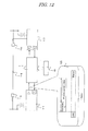
- FIG. 12 shows a specific image when the present invention is applied to an actual current-differential relay system.
- the protection system is realized by relays that mutually send electric quantity data at respective local terminals.
- a format 120 indicated by a balloon indicates that a transmission data frame is configured by a header, electric quantity data, an authentication tag, and CRC (Cyclic Redundancy Check) in the case of a general-purpose communication network like Ethernet (registered trademark) .
- CRC Cyclic Redundancy Check
- the maximum length per frame is 1514 bytes, so that when the size of the authentication tag is 32 bits, the ratio of the size of the authentication tag which is 32 bits (an attack success probability is 10 -9 ) in the whole frame is very small, and it is apparent that addition of an authentication tag hardly affects the communication traffic.
- an effective security countermeasure can be applied to protection relays which mutually exchange protective-control data through a communication path like electric-line current-differential protection replays.
- FIG. 13 is a flowchart showing a process of executing current-differential calculation with the current/voltage data at the other terminal being zero when the verification result 25 indicates "mismatch of authentication tags (fraudulent data) in the current-differential protection system according to the sixth embodiment shown in FIG. 11 . Only when the verification result 25 indicates "match of authentication tags" (valid data), current-differential calculation is executed using the received current/voltage data at the other terminal. It is possible through such a process to suppress any use of fraudulent data for current-differential calculation, so that a current-differential protection system with better reliability can be provided.
- FIG. 14 is a logic circuit diagram showing a process of locking a trip instruction to the breaker 116 regardless of a result of current-differential calculation when the verification result 25 indicates "mismatch of authentication tags" in the current-differential protection system of the sixth embodiment shown in FIG. 11 .
- a result of a current-differential calculation is directly output to the breaker 116 as a trip instruction, but in the case of the example shown in FIG. 14 , a result of the current-differential calculation and the verification result 25 for authentication are subjected to an AND operation, and a result thereof is output to the breaker 116, so that only when the verification result 25 indicates "mismatch of authentication tags", no trip instruction is given to the breaker 116. According to such a process, the breaker can be prevented from being tripped based on fraudulent data, and thus a current-differential protection system with a better reliability can be provided.
- FIG. 15 shows a protective-control measuring system of the seventh embodiment according to the present invention, and is a diagram showing characteristic data processing and data flow when, in particular, the protective-control measuring system of the first embodiment is applied to a substation control system.
- a substation control system is a system that causes a control computer 1501 outside a substation to transmit a control instruction 1503 to a control device 1502 installed in the substation, thereby controlling power equipment under the control of the control device 1502.
- FIG- 15 shows, as an example, a system which causes a control-instruction outputting unit 1504 of the control device 1502 to output a control signal 1505 in response to the control instruction 1503 from the control computer 1501, and which opens/closes and controls the breaker 116 in the substation.
- An operation terminal 1506 is connected to the control computer 1501. An explanation will be given below of an operation of the system when an operator issues the operation instruction 1503 from the operation terminal 1506 to the breaker 116.
- control instruction 1503 When the operator issues the control instruction 1503 to the breaker 116 from the operation terminal 1506 connected to the control computer 1501, the control instruction 1503 is input into the transmitter/receiver unit 14 and the authentication-tag generator unit 13 of the control computer 1501.
- the authentication-tag generator unit 13 generates the authentication tag 23 by using the control instruction 1503 and the key data 22.
- the transmitter/receiver unit 14 sends the transmission data 24 that is a combination of the control instruction 1503 and the authentication tag 23 to the control device 1502.
- the control device 1502 When receiving the data sent as the received data 24a through the transmitter/receiver unit 14 from the control computer 1501, the control device 1502 inputs the control instruction 1503a from the control computer 1501 and in the received data 24a into the control-instruction outputting unit 1504 and the authentication-tag generator unit 13.
- the authentication-tag generator unit 13 generates the authentication tag 23b for comparison by using the received control instruction 1503a and the key data 22.
- the generated authentication tag 23b for comparison and the authentication tag 23a in the received data 24a are input into the received-data authentication unit 15.
- the received-data authentication unit 15 performs authentication verification on whether or not those two authentication tags 23a and 23b match with each other, and passes the verification result 25 to the control-instruction outputting unit 1504.
- control-instruction outputting unit 1504 Only when the verification result 25 indicates "matching of the authentication tags" (a correct control instructions), the control-instruction outputting unit 1504 outputs the control signal 1505 in accordance with the received control instruction 1503a to the breaker 116.
- the present invention is not limited to the above-explained embodiments, and can be changed and modified in various forms within the scope and spirit of the present invention. That is, device configurations shown in the figures are merely examples showing minimum requisite functional configurations in order to realize the present invention, and specific hardware configuration and software configuration of each unit can be selected accordingly.
- the present invention can employ a configuration in which, as the transmitter/receiver unit of the protective-control measuring device, a transmitted unit and a receiver unit separated physically are provided or the authentication-tag generator unit for transmission and the authentication-tag generator unit for authentication are individually provided.
Applications Claiming Priority (2)
| Application Number | Priority Date | Filing Date | Title |
|---|---|---|---|
| JP2009008823A JP5374752B2 (ja) | 2009-01-19 | 2009-01-19 | 保護制御計測システムと装置、およびデータ伝送方法 |
| PCT/JP2009/007327 WO2010082284A1 (ja) | 2009-01-19 | 2009-12-28 | 保護制御計測システムと装置、およびデータ伝送方法 |
Publications (3)
| Publication Number | Publication Date |
|---|---|
| EP2381615A1 true EP2381615A1 (de) | 2011-10-26 |
| EP2381615A4 EP2381615A4 (de) | 2017-06-21 |
| EP2381615B1 EP2381615B1 (de) | 2018-04-18 |
Family
ID=42339554
Family Applications (1)
| Application Number | Title | Priority Date | Filing Date |
|---|---|---|---|
| EP09838254.2A Not-in-force EP2381615B1 (de) | 2009-01-19 | 2009-12-28 | System und vorrichtung für schutzkontrollinstrument und datenübertragungsverfahren |
Country Status (5)
| Country | Link |
|---|---|
| US (1) | US8547201B2 (de) |
| EP (1) | EP2381615B1 (de) |
| JP (1) | JP5374752B2 (de) |
| CN (1) | CN102282799B (de) |
| WO (1) | WO2010082284A1 (de) |
Cited By (1)
| Publication number | Priority date | Publication date | Assignee | Title |
|---|---|---|---|---|
| WO2015145090A1 (fr) * | 2014-03-28 | 2015-10-01 | Orange | Procédé de sélection de clé pour traitement cryptographique de données |
Families Citing this family (12)
| Publication number | Priority date | Publication date | Assignee | Title |
|---|---|---|---|---|
| KR20120027296A (ko) * | 2009-05-05 | 2012-03-21 | 코닌클리케 필립스 일렉트로닉스 엔.브이. | 무선 네트워크에서의 통신들을 보안화하는 방법 및 이를 위한 자원-제한된 디바이스 |
| KR101425699B1 (ko) * | 2010-05-07 | 2014-08-01 | 엘에스산전 주식회사 | 디지털 보호 계전기의 원방 통신 방법 |
| FR2987504B1 (fr) * | 2012-02-28 | 2014-06-27 | Schneider Electric Ind Sas | Bloc fonctionnel de mesure pour poste de distribution moyenne tension |
| JP2013197759A (ja) * | 2012-03-16 | 2013-09-30 | Toshiba Corp | 保護制御計測システムと装置、およびデータ伝送方法 |
| JP6104609B2 (ja) * | 2013-01-15 | 2017-03-29 | 株式会社東芝 | 送電線保護装置及び送電線保護システム |
| JP6462521B2 (ja) * | 2015-07-31 | 2019-01-30 | 株式会社日立超エル・エス・アイ・システムズ | 通常部の故障が安全部へ伝播することを防止するapi及びその処理部 |
| JP6832794B2 (ja) * | 2017-06-05 | 2021-02-24 | ルネサスエレクトロニクス株式会社 | 無線通信システム |
| CN108199837B (zh) * | 2018-01-23 | 2020-12-25 | 新华三信息安全技术有限公司 | 一种密钥协商方法及装置 |
| CN110636028B (zh) * | 2018-06-21 | 2021-07-27 | 蔡利锋 | 密钥生成装置、加密装置、密钥生成和分发系统 |
| KR20220020932A (ko) * | 2019-07-18 | 2022-02-21 | 가부시끼가이샤 도시바 | 보호 계전 장치 |
| US11017846B2 (en) | 2019-08-26 | 2021-05-25 | Micron Technology, Inc. | Updating program files of a memory device using a differential write operation |
| US11201857B2 (en) * | 2019-12-09 | 2021-12-14 | Disney Enterprises, Inc. | Domain transcendent file cryptology network |
Family Cites Families (16)
| Publication number | Priority date | Publication date | Assignee | Title |
|---|---|---|---|---|
| JPH10269180A (ja) * | 1997-03-26 | 1998-10-09 | Toshiba Corp | 情報機器におけるセキュリティ解除方法、ならびに同方法を実現するセキュリティシステム |
| JPH10303881A (ja) * | 1997-04-25 | 1998-11-13 | Sony Corp | 暗号化復号化装置および方法 |
| JP2000194262A (ja) * | 1998-12-24 | 2000-07-14 | Toshiba Corp | 完全性データ収集装置、データ検証装置およびこれらを用いたプラントデータ証明システム |
| JP2000228821A (ja) * | 1999-02-08 | 2000-08-15 | Meidensha Corp | 光pcm電流差動リレー方式 |
| JP2000295209A (ja) * | 1999-04-09 | 2000-10-20 | Ntt Data Corp | 鍵管理方法、鍵管理システム及び記録媒体 |
| JP2001175606A (ja) * | 1999-12-20 | 2001-06-29 | Sony Corp | データ処理装置、データ処理機器およびその方法 |
| US7360075B2 (en) * | 2001-02-12 | 2008-04-15 | Aventail Corporation, A Wholly Owned Subsidiary Of Sonicwall, Inc. | Method and apparatus for providing secure streaming data transmission facilities using unreliable protocols |
| US7350069B2 (en) * | 2002-04-18 | 2008-03-25 | Herz Frederick S M | System and method which employs a multi user secure scheme utilizing shared keys |
| JP2003333023A (ja) * | 2002-05-09 | 2003-11-21 | Toshiba Corp | プラント監視制御用データ中継プログラムおよびシステム |
| US6965674B2 (en) * | 2002-05-21 | 2005-11-15 | Wavelink Corporation | System and method for providing WLAN security through synchronized update and rotation of WEP keys |
| JP2004158981A (ja) * | 2002-11-05 | 2004-06-03 | Toshiba Corp | 通信装置及び通信方法 |
| US7694330B2 (en) * | 2003-05-23 | 2010-04-06 | Industrial Technology Research Institute | Personal authentication device and system and method thereof |
| JP4522098B2 (ja) * | 2004-01-13 | 2010-08-11 | 株式会社エヌ・ティ・ティ・データ | アプリケーションパーソナライズシステム |
| JP2005217907A (ja) * | 2004-01-30 | 2005-08-11 | Tm T & D Kk | 遠方監視制御装置、遠方監視制御方法およびそのプログラム |
| US7689828B2 (en) * | 2004-07-23 | 2010-03-30 | Data Security Systems Solutions Pte Ltd | System and method for implementing digital signature using one time private keys |
| CN100459495C (zh) * | 2004-08-01 | 2009-02-04 | 常志文 | 一种公开加密方式的口令动态加密输入方法 |
-
2009
- 2009-01-19 JP JP2009008823A patent/JP5374752B2/ja not_active Expired - Fee Related
- 2009-12-28 EP EP09838254.2A patent/EP2381615B1/de not_active Not-in-force
- 2009-12-28 WO PCT/JP2009/007327 patent/WO2010082284A1/ja active Application Filing
- 2009-12-28 CN CN200980155003.XA patent/CN102282799B/zh not_active Expired - Fee Related
- 2009-12-28 US US13/145,120 patent/US8547201B2/en not_active Expired - Fee Related
Non-Patent Citations (1)
| Title |
|---|
| See references of WO2010082284A1 * |
Cited By (3)
| Publication number | Priority date | Publication date | Assignee | Title |
|---|---|---|---|---|
| WO2015145090A1 (fr) * | 2014-03-28 | 2015-10-01 | Orange | Procédé de sélection de clé pour traitement cryptographique de données |
| FR3019416A1 (fr) * | 2014-03-28 | 2015-10-02 | Orange | Procede de traitement de donnees |
| US10931444B2 (en) | 2014-03-28 | 2021-02-23 | Orange | Key selection method for cryptographic data processing |
Also Published As
| Publication number | Publication date |
|---|---|
| JP2010166486A (ja) | 2010-07-29 |
| JP5374752B2 (ja) | 2013-12-25 |
| EP2381615B1 (de) | 2018-04-18 |
| US20120019355A1 (en) | 2012-01-26 |
| WO2010082284A1 (ja) | 2010-07-22 |
| CN102282799B (zh) | 2014-04-30 |
| EP2381615A4 (de) | 2017-06-21 |
| CN102282799A (zh) | 2011-12-14 |
| US8547201B2 (en) | 2013-10-01 |
Similar Documents
| Publication | Publication Date | Title |
|---|---|---|
| EP2381615B1 (de) | System und vorrichtung für schutzkontrollinstrument und datenübertragungsverfahren | |
| EP2290872B1 (de) | Vorrichtung zur Erzeugung eines Nachrichtenauthentifizierungscodes zur Authentifizierung einer Nachricht | |
| KR101351012B1 (ko) | 다자간 양자 통신에서의 사용자 인증 방법 및 장치 | |
| CN102780698A (zh) | 物联网平台中用户终端安全通信的方法 | |
| US10425231B2 (en) | Information processing apparatus and method for authenticating message | |
| CN110474892B (zh) | 一种基于区块链技术的虚假数据注入攻击防御方法 | |
| Saxena et al. | Efficient signature scheme for delivering authentic control commands in the smart grid | |
| CN110601822A (zh) | 一种基于量子保密通信技术的加密盲签名方法 | |
| CN107493168A (zh) | 量子身份认证方法及其在量子密钥分发过程中的应用方法 | |
| US9559838B2 (en) | Method of processing data protected against fault injection attacks and associated device | |
| CN110048994A (zh) | 一种通信方法和装置 | |
| EP3304801B1 (de) | System und verfahren zum schutz einer kryptografischen vorrichtung gegen fehlerangriffe bei der durchführung von kryptografischen nichtlinearen operationen mithilfe linearer fehlerkorrekturcodes | |
| CN108352991A (zh) | 信息处理装置以及不正当消息检测方法 | |
| Jolfaei et al. | A lightweight integrity protection scheme for fast communications in smart grid | |
| CN110278068B (zh) | 基于混沌序列的LoRa通信加密系统 | |
| JP2015204508A (ja) | 情報処理システム及びデータ転送方法 | |
| CN114363094A (zh) | 一种数据分享方法、装置、设备及存储介质 | |
| CN113489589A (zh) | 数据加密、解密方法、装置及电子设备 | |
| CN102804724B (zh) | 在自动化装置之间防操纵的数据传输 | |
| JP2013197759A (ja) | 保護制御計測システムと装置、およびデータ伝送方法 | |
| Watanabe et al. | Proposal of WEP Operation with Strong IV and Its Implementation | |
| Baoyi et al. | Research on WSN secure communication method based on digital watermark for the monitoring of electric transmission lines | |
| Tsiakkas et al. | Establishing data integrity in networks of cyber-physical systems | |
| US20230299957A1 (en) | Protection of a secret key | |
| EP4333366A1 (de) | Leichte fehlergegenmassnahme für zustandsbehaftete hash-basierte kryptographie |
Legal Events
| Date | Code | Title | Description |
|---|---|---|---|
| PUAI | Public reference made under article 153(3) epc to a published international application that has entered the european phase |
Free format text: ORIGINAL CODE: 0009012 |
|
| 17P | Request for examination filed |
Effective date: 20110718 |
|
| AK | Designated contracting states |
Kind code of ref document: A1 Designated state(s): AT BE BG CH CY CZ DE DK EE ES FI FR GB GR HR HU IE IS IT LI LT LU LV MC MK MT NL NO PL PT RO SE SI SK SM TR |
|
| DAX | Request for extension of the european patent (deleted) | ||
| RA4 | Supplementary search report drawn up and despatched (corrected) |
Effective date: 20170522 |
|
| RIC1 | Information provided on ipc code assigned before grant |
Ipc: H04L 9/14 20060101ALI20170516BHEP Ipc: H04L 9/32 20060101AFI20170516BHEP Ipc: H04L 9/16 20060101ALI20170516BHEP Ipc: H04L 9/08 20060101ALI20170516BHEP |
|
| GRAP | Despatch of communication of intention to grant a patent |
Free format text: ORIGINAL CODE: EPIDOSNIGR1 |
|
| INTG | Intention to grant announced |
Effective date: 20171024 |
|
| GRAS | Grant fee paid |
Free format text: ORIGINAL CODE: EPIDOSNIGR3 |
|
| GRAA | (expected) grant |
Free format text: ORIGINAL CODE: 0009210 |
|
| RAP1 | Party data changed (applicant data changed or rights of an application transferred) |
Owner name: TOSHIBA ENERGY SYSTEMS & SOLUTIONS CORPORATION Owner name: YOKOHAMA NATIONAL UNIVERSITY |
|
| AK | Designated contracting states |
Kind code of ref document: B1 Designated state(s): AT BE BG CH CY CZ DE DK EE ES FI FR GB GR HR HU IE IS IT LI LT LU LV MC MK MT NL NO PL PT RO SE SI SK SM TR |
|
| REG | Reference to a national code |
Ref country code: GB Ref legal event code: FG4D |
|
| REG | Reference to a national code |
Ref country code: CH Ref legal event code: EP |
|
| REG | Reference to a national code |
Ref country code: AT Ref legal event code: REF Ref document number: 991560 Country of ref document: AT Kind code of ref document: T Effective date: 20180515 |
|
| REG | Reference to a national code |
Ref country code: IE Ref legal event code: FG4D |
|
| REG | Reference to a national code |
Ref country code: DE Ref legal event code: R096 Ref document number: 602009051911 Country of ref document: DE |
|
| REG | Reference to a national code |
Ref country code: SE Ref legal event code: TRGR |
|
| REG | Reference to a national code |
Ref country code: NL Ref legal event code: MP Effective date: 20180418 |
|
| REG | Reference to a national code |
Ref country code: LT Ref legal event code: MG4D |
|
| PG25 | Lapsed in a contracting state [announced via postgrant information from national office to epo] |
Ref country code: NL Free format text: LAPSE BECAUSE OF FAILURE TO SUBMIT A TRANSLATION OF THE DESCRIPTION OR TO PAY THE FEE WITHIN THE PRESCRIBED TIME-LIMIT Effective date: 20180418 |
|
| PG25 | Lapsed in a contracting state [announced via postgrant information from national office to epo] |
Ref country code: FI Free format text: LAPSE BECAUSE OF FAILURE TO SUBMIT A TRANSLATION OF THE DESCRIPTION OR TO PAY THE FEE WITHIN THE PRESCRIBED TIME-LIMIT Effective date: 20180418 Ref country code: BG Free format text: LAPSE BECAUSE OF FAILURE TO SUBMIT A TRANSLATION OF THE DESCRIPTION OR TO PAY THE FEE WITHIN THE PRESCRIBED TIME-LIMIT Effective date: 20180718 Ref country code: NO Free format text: LAPSE BECAUSE OF FAILURE TO SUBMIT A TRANSLATION OF THE DESCRIPTION OR TO PAY THE FEE WITHIN THE PRESCRIBED TIME-LIMIT Effective date: 20180718 Ref country code: ES Free format text: LAPSE BECAUSE OF FAILURE TO SUBMIT A TRANSLATION OF THE DESCRIPTION OR TO PAY THE FEE WITHIN THE PRESCRIBED TIME-LIMIT Effective date: 20180418 Ref country code: LT Free format text: LAPSE BECAUSE OF FAILURE TO SUBMIT A TRANSLATION OF THE DESCRIPTION OR TO PAY THE FEE WITHIN THE PRESCRIBED TIME-LIMIT Effective date: 20180418 Ref country code: PL Free format text: LAPSE BECAUSE OF FAILURE TO SUBMIT A TRANSLATION OF THE DESCRIPTION OR TO PAY THE FEE WITHIN THE PRESCRIBED TIME-LIMIT Effective date: 20180418 |
|
| PG25 | Lapsed in a contracting state [announced via postgrant information from national office to epo] |
Ref country code: HR Free format text: LAPSE BECAUSE OF FAILURE TO SUBMIT A TRANSLATION OF THE DESCRIPTION OR TO PAY THE FEE WITHIN THE PRESCRIBED TIME-LIMIT Effective date: 20180418 Ref country code: LV Free format text: LAPSE BECAUSE OF FAILURE TO SUBMIT A TRANSLATION OF THE DESCRIPTION OR TO PAY THE FEE WITHIN THE PRESCRIBED TIME-LIMIT Effective date: 20180418 Ref country code: GR Free format text: LAPSE BECAUSE OF FAILURE TO SUBMIT A TRANSLATION OF THE DESCRIPTION OR TO PAY THE FEE WITHIN THE PRESCRIBED TIME-LIMIT Effective date: 20180719 |
|
| REG | Reference to a national code |
Ref country code: AT Ref legal event code: MK05 Ref document number: 991560 Country of ref document: AT Kind code of ref document: T Effective date: 20180418 |
|
| PG25 | Lapsed in a contracting state [announced via postgrant information from national office to epo] |
Ref country code: PT Free format text: LAPSE BECAUSE OF FAILURE TO SUBMIT A TRANSLATION OF THE DESCRIPTION OR TO PAY THE FEE WITHIN THE PRESCRIBED TIME-LIMIT Effective date: 20180820 |
|
| REG | Reference to a national code |
Ref country code: DE Ref legal event code: R097 Ref document number: 602009051911 Country of ref document: DE |
|
| PG25 | Lapsed in a contracting state [announced via postgrant information from national office to epo] |
Ref country code: EE Free format text: LAPSE BECAUSE OF FAILURE TO SUBMIT A TRANSLATION OF THE DESCRIPTION OR TO PAY THE FEE WITHIN THE PRESCRIBED TIME-LIMIT Effective date: 20180418 Ref country code: RO Free format text: LAPSE BECAUSE OF FAILURE TO SUBMIT A TRANSLATION OF THE DESCRIPTION OR TO PAY THE FEE WITHIN THE PRESCRIBED TIME-LIMIT Effective date: 20180418 Ref country code: CZ Free format text: LAPSE BECAUSE OF FAILURE TO SUBMIT A TRANSLATION OF THE DESCRIPTION OR TO PAY THE FEE WITHIN THE PRESCRIBED TIME-LIMIT Effective date: 20180418 Ref country code: AT Free format text: LAPSE BECAUSE OF FAILURE TO SUBMIT A TRANSLATION OF THE DESCRIPTION OR TO PAY THE FEE WITHIN THE PRESCRIBED TIME-LIMIT Effective date: 20180418 Ref country code: DK Free format text: LAPSE BECAUSE OF FAILURE TO SUBMIT A TRANSLATION OF THE DESCRIPTION OR TO PAY THE FEE WITHIN THE PRESCRIBED TIME-LIMIT Effective date: 20180418 Ref country code: SK Free format text: LAPSE BECAUSE OF FAILURE TO SUBMIT A TRANSLATION OF THE DESCRIPTION OR TO PAY THE FEE WITHIN THE PRESCRIBED TIME-LIMIT Effective date: 20180418 |
|
| PLBE | No opposition filed within time limit |
Free format text: ORIGINAL CODE: 0009261 |
|
| STAA | Information on the status of an ep patent application or granted ep patent |
Free format text: STATUS: NO OPPOSITION FILED WITHIN TIME LIMIT |
|
| PG25 | Lapsed in a contracting state [announced via postgrant information from national office to epo] |
Ref country code: SM Free format text: LAPSE BECAUSE OF FAILURE TO SUBMIT A TRANSLATION OF THE DESCRIPTION OR TO PAY THE FEE WITHIN THE PRESCRIBED TIME-LIMIT Effective date: 20180418 Ref country code: IT Free format text: LAPSE BECAUSE OF FAILURE TO SUBMIT A TRANSLATION OF THE DESCRIPTION OR TO PAY THE FEE WITHIN THE PRESCRIBED TIME-LIMIT Effective date: 20180418 |
|
| 26N | No opposition filed |
Effective date: 20190121 |
|
| PG25 | Lapsed in a contracting state [announced via postgrant information from national office to epo] |
Ref country code: SI Free format text: LAPSE BECAUSE OF FAILURE TO SUBMIT A TRANSLATION OF THE DESCRIPTION OR TO PAY THE FEE WITHIN THE PRESCRIBED TIME-LIMIT Effective date: 20180418 |
|
| REG | Reference to a national code |
Ref country code: DE Ref legal event code: R119 Ref document number: 602009051911 Country of ref document: DE |
|
| REG | Reference to a national code |
Ref country code: SE Ref legal event code: EUG |
|
| PG25 | Lapsed in a contracting state [announced via postgrant information from national office to epo] |
Ref country code: SE Free format text: LAPSE BECAUSE OF NON-PAYMENT OF DUE FEES Effective date: 20181229 |
|
| REG | Reference to a national code |
Ref country code: CH Ref legal event code: PL |
|
| GBPC | Gb: european patent ceased through non-payment of renewal fee |
Effective date: 20181228 |
|
| PG25 | Lapsed in a contracting state [announced via postgrant information from national office to epo] |
Ref country code: LU Free format text: LAPSE BECAUSE OF NON-PAYMENT OF DUE FEES Effective date: 20181228 Ref country code: MC Free format text: LAPSE BECAUSE OF FAILURE TO SUBMIT A TRANSLATION OF THE DESCRIPTION OR TO PAY THE FEE WITHIN THE PRESCRIBED TIME-LIMIT Effective date: 20180418 |
|
| REG | Reference to a national code |
Ref country code: IE Ref legal event code: MM4A |
|
| REG | Reference to a national code |
Ref country code: BE Ref legal event code: MM Effective date: 20181231 |
|
| PG25 | Lapsed in a contracting state [announced via postgrant information from national office to epo] |
Ref country code: IE Free format text: LAPSE BECAUSE OF NON-PAYMENT OF DUE FEES Effective date: 20181228 Ref country code: DE Free format text: LAPSE BECAUSE OF NON-PAYMENT OF DUE FEES Effective date: 20190702 Ref country code: FR Free format text: LAPSE BECAUSE OF NON-PAYMENT OF DUE FEES Effective date: 20181231 |
|
| PG25 | Lapsed in a contracting state [announced via postgrant information from national office to epo] |
Ref country code: BE Free format text: LAPSE BECAUSE OF NON-PAYMENT OF DUE FEES Effective date: 20181231 |
|
| PG25 | Lapsed in a contracting state [announced via postgrant information from national office to epo] |
Ref country code: LI Free format text: LAPSE BECAUSE OF NON-PAYMENT OF DUE FEES Effective date: 20181231 Ref country code: GB Free format text: LAPSE BECAUSE OF NON-PAYMENT OF DUE FEES Effective date: 20181228 Ref country code: CH Free format text: LAPSE BECAUSE OF NON-PAYMENT OF DUE FEES Effective date: 20181231 |
|
| PG25 | Lapsed in a contracting state [announced via postgrant information from national office to epo] |
Ref country code: MT Free format text: LAPSE BECAUSE OF NON-PAYMENT OF DUE FEES Effective date: 20181228 |
|
| PG25 | Lapsed in a contracting state [announced via postgrant information from national office to epo] |
Ref country code: TR Free format text: LAPSE BECAUSE OF FAILURE TO SUBMIT A TRANSLATION OF THE DESCRIPTION OR TO PAY THE FEE WITHIN THE PRESCRIBED TIME-LIMIT Effective date: 20180418 |
|
| PG25 | Lapsed in a contracting state [announced via postgrant information from national office to epo] |
Ref country code: CY Free format text: LAPSE BECAUSE OF FAILURE TO SUBMIT A TRANSLATION OF THE DESCRIPTION OR TO PAY THE FEE WITHIN THE PRESCRIBED TIME-LIMIT Effective date: 20180418 Ref country code: MK Free format text: LAPSE BECAUSE OF NON-PAYMENT OF DUE FEES Effective date: 20180418 Ref country code: HU Free format text: LAPSE BECAUSE OF FAILURE TO SUBMIT A TRANSLATION OF THE DESCRIPTION OR TO PAY THE FEE WITHIN THE PRESCRIBED TIME-LIMIT; INVALID AB INITIO Effective date: 20091228 |
|
| PG25 | Lapsed in a contracting state [announced via postgrant information from national office to epo] |
Ref country code: IS Free format text: LAPSE BECAUSE OF FAILURE TO SUBMIT A TRANSLATION OF THE DESCRIPTION OR TO PAY THE FEE WITHIN THE PRESCRIBED TIME-LIMIT Effective date: 20180818 |