EP2381253A2 - Apparatus for detecting toxicity in water using sulfur-oxidizing bacteria - Google Patents
Apparatus for detecting toxicity in water using sulfur-oxidizing bacteria Download PDFInfo
- Publication number
- EP2381253A2 EP2381253A2 EP11163029A EP11163029A EP2381253A2 EP 2381253 A2 EP2381253 A2 EP 2381253A2 EP 11163029 A EP11163029 A EP 11163029A EP 11163029 A EP11163029 A EP 11163029A EP 2381253 A2 EP2381253 A2 EP 2381253A2
- Authority
- EP
- European Patent Office
- Prior art keywords
- water sample
- reactor
- water
- sulfur
- measurement chamber
- Prior art date
- Legal status (The legal status is an assumption and is not a legal conclusion. Google has not performed a legal analysis and makes no representation as to the accuracy of the status listed.)
- Granted
Links
Images






Classifications
-
- G—PHYSICS
- G01—MEASURING; TESTING
- G01N—INVESTIGATING OR ANALYSING MATERIALS BY DETERMINING THEIR CHEMICAL OR PHYSICAL PROPERTIES
- G01N33/00—Investigating or analysing materials by specific methods not covered by groups G01N1/00 - G01N31/00
- G01N33/18—Water
- G01N33/186—Water using one or more living organisms, e.g. a fish
- G01N33/1866—Water using one or more living organisms, e.g. a fish using microorganisms
-
- C—CHEMISTRY; METALLURGY
- C12—BIOCHEMISTRY; BEER; SPIRITS; WINE; VINEGAR; MICROBIOLOGY; ENZYMOLOGY; MUTATION OR GENETIC ENGINEERING
- C12Q—MEASURING OR TESTING PROCESSES INVOLVING ENZYMES, NUCLEIC ACIDS OR MICROORGANISMS; COMPOSITIONS OR TEST PAPERS THEREFOR; PROCESSES OF PREPARING SUCH COMPOSITIONS; CONDITION-RESPONSIVE CONTROL IN MICROBIOLOGICAL OR ENZYMOLOGICAL PROCESSES
- C12Q1/00—Measuring or testing processes involving enzymes, nucleic acids or microorganisms; Compositions therefor; Processes of preparing such compositions
- C12Q1/02—Measuring or testing processes involving enzymes, nucleic acids or microorganisms; Compositions therefor; Processes of preparing such compositions involving viable microorganisms
-
- G—PHYSICS
- G01—MEASURING; TESTING
- G01N—INVESTIGATING OR ANALYSING MATERIALS BY DETERMINING THEIR CHEMICAL OR PHYSICAL PROPERTIES
- G01N2520/00—Use of whole organisms as detectors of pollution
Definitions
- the present invention relates to an apparatus for detecting toxicity in water using sulfur-oxidizing bacteria, and more particularly to an apparatus for detecting toxicity in water using sulfur-oxidizing bacteria, which can provide accurate results of toxicity detection.
- Korean Patent Laid-Open Publication No. 2009-28138 filed in the name of this applicant discloses an apparatus for detecting toxicity in water using sulfur particles.
- FIG. 1 is a schematic view showing the configuration of the water toxicity-detecting apparatus disclosed in the above publication.
- a water toxicity-detecting apparatus 1 comprises: a microbial reactor into which a water sample is introduced and which contains sulfur-oxidizing bacteria and sulfur particles; a first measurement unit 4 placed on the inlet side of the microbial reactor 2; and a second measurement unit 5 placed inside the microbial reactor 2.
- whether the water sample has toxicity is determined by comparing the electrical conductivity (EC) and pH values, measured in the first measurement unit 4, with those measured in the second measurement unit 5.
- EC electrical conductivity
- the invention disclosed in the above publication relates to a method and apparatus of detecting toxicity in water by determining the activity of sulfur-oxidizing bacteria on the basis of electrical conductivity and pH.
- the electrical conductivity of water allows prediction of the amount of the total salts and total ions dissolved in the water.
- the change in electrical conductivity (EC) can be considered as the change in concentration of sulfate ions.
- electrical conductivity is measured by placing two metals (electrodes) at a distance from each other in ion-containing water, applying voltage across the electrodes and measuring the generated current.
- the electrical conductivity-measuring unit has a problem in that, when air bubbles enter between the two electrodes, the data will fluctuate instantaneously, thus making it difficult to obtain accurate experimental values.
- the sulfur-oxidizing bacteria present in the reactor are autotrophic microorganisms that use carbon dioxide as a carbon source and require micronutrients such as nitrogen, phosphorus and potassium.
- the water toxicity-detecting apparatus disclosed in the above publication is not effective in detecting toxicity in highly purified water containing little or no carbon dioxide and nutrients.
- the sulfur-oxidizing bacteria present in the reactor are inactivated by toxic substances, it is impossible to continuously detect toxicity in an additional water sample. Namely, the sulfur particles should be replaced, and a time of about 2-14 days is required to reactivate the sulfur-oxidizing bacteria. During reactivation of the sulfur-oxidizing bacteria are reactivated, it is impossible to detect toxicity in the water sample.
- the present invention has been made in view of the problems occurring in the prior art, and it is an object of the present invention to provide an apparatus for detecting toxicity in water using sulfur-oxidizing bacteria, in which a measurement unit is not affected by air bubbles generated by air aeration in a microbial reactor, so that accurate experimental results can be obtained.
- Another object of the present invention is to provide an apparatus for detecting toxicity in water using sulfur-oxidizing bacteria, which can provide accurate experimental results even when extremely clean water, extremely contaminated water or a water sample having a very high pH is tested.
- Still another object of the present invention is to provide an apparatus for detecting toxicity in water using sulfur-oxidizing bacteria, which further comprises an additional reactor that allows toxicity detection to be continuously performed even when sulfur-oxidizing bacteria present in one reactor are inactivated.
- the present invention provides an apparatus for detecting toxicity in water using sulfur-oxidizing bacteria, the apparatus comprising: a microbial reactor comprising a reactor body which contains sulfur-oxidizing bacteria and in which sulfur particles are oxidized by the sulfur-oxidizing bacteria in the presence of oxygen to form sulfate ions, an inlet through which a water sample is introduced into the reactor body, and an air inlet through which air is supplied to the reactor body; a measurement unit for measuring the pH and electrical conductivity (EC) of the water sample containing the sulfate ions produced in the reactor body, in which the measurement unit is placed in a separated space so as not to be affected by air bubbles generated due to supply of air to the reactor body, the separated space communicating with the reactor body so that the water sample containing the sulfate ions produced in the reactor body is introduced into the measurement unit; and a control unit which compares the electrical conductivity (EC) and pH values measured in the measurement unit with reference values to determine whether the water sample has toxicity.
- EC electrical conductivity
- the separated space in which the measurement unit for measuring pH and electrical conductivity (EC) are placed may be defined by a measurement chamber formed integrally with the outer surface of the reactor body, and a through-hole through which the water sample passes may be formed in the reactor body provided with the measurement chamber.
- a measurement chamber formed integrally with the outer surface of the reactor body, and a through-hole through which the water sample passes may be formed in the reactor body provided with the measurement chamber.
- the separated space in which the measurement unit for measuring pH and electrical conductivity (EC) is placed may be defined by a measurement chamber which is spaced apart from the reactor body and is connected with the reactor body by a connection pipe so that the water sample containing the sulfate ions produced in the reactor body is introduced into the measurement chamber through the connection pipe.
- a measurement chamber which is spaced apart from the reactor body and is connected with the reactor body by a connection pipe so that the water sample containing the sulfate ions produced in the reactor body is introduced into the measurement chamber through the connection pipe.
- the separated space in which the measurement unit for measuring pH and electrical conductivity (EC) is placed may be defined in an upper region of the reactor body by a partitioning plate which is placed around the inner surface of the reactor body to divide the inner space of the reactor body into upper and lower regions, and an opening through which the water sample passes may be formed around one side of the partitioning plate.
- a partitioning plate which is placed around the inner surface of the reactor body to divide the inner space of the reactor body into upper and lower regions, and an opening through which the water sample passes may be formed around one side of the partitioning plate.
- the apparatus of the present invention may further comprise a pH-adjusting unit which is placed on one side of the inlet of the microbial reactor and serves to supply an acidic substance to the water sample being supplied to the microbial reactor so as to adjust the pH of the water sample within the reference range.
- a pH-adjusting unit which is placed on one side of the inlet of the microbial reactor and serves to supply an acidic substance to the water sample being supplied to the microbial reactor so as to adjust the pH of the water sample within the reference range.
- the apparatus of the present invention may further comprise an auxiliary microbial reactor which is placed on one side of the microbial reactor and contains active sulfur-oxidizing bacteria, in which the auxiliary microbial reactor serves to detect toxicity in the water sample supplied from the microbial reactor when the sulfur-oxidizing bacteria in the microbial reactor were inactivated due to toxic substances.
- the auxiliary microbial reactor is operated by supplying minimum amounts of water and air thereto while the microbial reactor is used to detect toxicity in the water sample, and whether the sulfur-oxidizing bacteria have activity is monitored by measuring electrical conductivity.
- the apparatus of the present invention may further comprise an auxiliary microbial reactor which is placed on one side of the microbial reactor, in which the auxiliary microbial reactor and the microbial reactor are alternately supplied with the water sample and a diluted water sample to determine whether the water sample has toxicity.
- FIG. 2 is a schematic view showing the entire configuration of an apparatus for detecting toxicity in water using sulfur-oxidizing bacteria according to the present invention.
- an apparatus 10 for detecting toxicity in water using sulfur-oxidizing bacteria comprises: a microbial reactor 100 which contains sulfur-oxidizing bacteria and in which the sulfur-oxidizing bacteria uses oxygen and sulfur particles as an electron acceptor and an electron donor, respectively, to form sulfate ions; a measurement unit 300 for measuring the pH and electrical conductivity (EC) of a water sample containing the sulfate ions generated in the microbial reactor 100; a raw water supply unit 400 for supplying the water sample; a pH-adjusting unit 500 which is disposed between the raw water supply unit 400 and an inlet 120 of the microbial reactor 100 and serves to adjust the pH of the water sample; and a control unit 600 for determining whether the water sample has toxicity on the basis of results measured in the measurement unit 300.
- a microbial reactor 100 which contains sulfur-oxidizing bacteria and in which the sulfur-oxidizing bacteria uses oxygen and sulfur particles as an electron acceptor and an electron donor, respectively, to form sulfate ions
- a measurement unit 300 for measuring the pH and
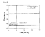
- determining whether the water sample has toxicity on the basis of the results measured in the measurement unit 300 can be performed using various methods. For example, whether the water sample has toxicity can be determined by comparing the pH and electrical conductivity (EC) values of the water sample, which is introduced into the microbial reactor 100, with those measured in the measurement unit 300. Also, as shown in FIG. 13 , whether the water sample has toxicity can be determined by comparing the change in EC of a synthetic stream water having no toxicity for a specific time (EC 12h for control) with the change in EC of a water sample for a specific time (EC 12h for sample), measured in the measurement unit 300.
- EC electrical conductivity
- the microbial reactor 100 contains sulfur particles and active sulfur-oxidizing bacteria, and thus sulfate ions are produced therein.
- the microbial reactor 100 comprises: a reactor body 110 in which a water sample and sulfur-oxidizing bacteria are placed; an inlet 120 which is connected to the lower region of the reactor body 110 and serves to introduce the water sample into the reactor body 110; an outlet 140 which is connected to the upper region of the reactor body 110 and serves to discharge the sample from the reactor body 110; and an air inlet 130 for supplying air to the interior of the reactor body 110.
- the water sample may be various kinds of water, including stream water, wastewater, and purified water.
- the sulfur-oxidizing bacteria present in the reactor body 110 grow attached to the surface of the sulfur particles, and the sulfur particles are oxidized at a constant rate to produce sulfate ions. If the water sample has no toxicity, the concentration of the sulfate ions will increase due to the oxidation of the sulfur particles caused by the activity of the sulfur-oxidizing bacteria. On the other hand, if the water sample has strong toxicity, the activity of the sulfur-oxidizing bacteria will decrease so that they cannot oxidize the sulfur particles, and thus the concentration of the sulfate ions will not substantially change with time goes by.
- the microbial reactor 100 functions as a biosensor for detecting the presence of toxicity in the water sample on the basis of this principle.
- the measurement unit 300 comprises a pH-measuring unit 320 and EC-measuring unit 330 for measuring the pH and electrical conductivity (EC) of the water sample containing the sulfate ions created by the oxidation of sulfur particles due to the activity of sulfur-oxidizing bacteria in the reactor body 110, and also comprises a space in which the pH-measuring unit 320 and the EC-measuring unit 330 are placed.
- the pH-measuring unit 320 and the EC-measuring unit 330 are provided in the form of electrodes.
- the pH-measuring unit 320 and the EC-measuring unit 330 are placed in a space separated from the reactor body 110 so that they are not affected by air bubbles generated by supply of the water sample and air.
- the separated space and the reactor body 110 communicate with each other so that the water sample containing the sulfate ions produced in the reactor body 110 can be introduced into the separated space.
- the separated space is formed outside the reactor body 110 in such a manner that it is integral with the reactor body 110 (first embodiment).
- the separated space is formed outside the reactor body 110 in such a manner that it is spaced from the reactor body 110 (second embodiment).
- the separated space is formed inside the reactor body 110 (third embodiment).
- a measurement chamber 310 defining the separated space is provided outside the reactor body 110 in such a manner that it is integral with the reactor body 110, so that it is not affected by air bubbles generated by aeration by a water sample and air.
- the measurement chamber 310 is provided integrally with the outside of the upper region of the reactor body 110, and a through-hole 311 through which a water sample can pass is formed in the reactor body 110 provided with the measurement chamber 310, so that the water sample flows from the reactor body 110 into the measurement chamber 310.
- the pH-measuring unit 320 and the EC-measuring unit 330 are received so that they measure the physical properties of the water sample.
- the pH-measuring unit 320 and the EC-measuring unit 330 is out of the path of movement of air bubbles generated by aeration of the water sample and air, which are introduced through the inlet 120 and the air inlet 130, respectively.
- air bubbles generated when the water sample and air flow can be prevented from coming into contact with and impacting the pH-measuring unit 320 and the EC-measuring unit 330.
- the pH-measuring unit 320 and the EC-measuring unit 330 can provide more accurate measurement data.
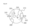
- the measurement chamber 310 which defines the separated space, and the reactor body 310 are spaced apart from each other and communicated with each other by a connection pipe 160.
- the measurement chamber 310 is spaced apart from the reactor body 110, it is connected with the reactor body 110 by the connection pipe 160, and thus can be supplied with the water sample containing the sulfate ions produced in the reactor body 110.
- connection pipe 160 is connected with each of the outlet 140 of the microbial reactor 100 and the inlet 340 of the measurement chamber 310.
- the inlet 340 of the measurement chamber 310 is placed at a level lower than the outlet 140 of the reactor body 110 so that the water sample containing the sulfate ions produced in the reactor body 110 can naturally flow into the measurement chamber 310.
- the top of the measurement chamber 310 is provided with a cover 360 capable of covering the measurement chamber 310.
- a cover 360 capable of covering the measurement chamber 310.
- two through-pipes 370 are provided so that the pH-measuring unit 320 and the EC-measuring unit 330 can be inserted into the measurement chamber 310 through the through-pipes 370.
- an outlet 350 through which the water sample introduced into the measurement chamber 310 can be discharged is provided on the side opposite to the inlet 340.
- the pH-measuring unit 320 and EC-measuring unit 330 for measuring the pH and electrical conductivity of the water sample containing the sulfate ions produced in the microbial reactor 100 are provided in such a manner that they are completely separated from the microbial reactor 100.
- air bubbles generated by air aeration in the microbial reactor 100 can be prevented from coming into contact with and impacting the pH-measuring unit 320 and the EC-measuring unit 330.
- the pH-measuring unit 320 and the EC-measuring unit 330 can provide more accurate measurement results.
- the supply of the water sample from the microbial reactor 100 to the measurement chamber 310 can be naturally achieved without an additional powder device such as a pump.
- the entire structure of the apparatus can be simplified so that the apparatus can be installed in a relatively narrow space and the installation cost of the apparatus can be reduced.
- the measurement chamber 310 does not contain sulfur-oxidizing bacteria and sulfur particles and does not require air aeration, unlike the microbial reactor 100, and the capacity thereof needs to be minimized compared to the microbial reactor 100. If the capacity of the measurement chamber 310 is excessively small, short circuiting can occur so that the water sample introduced into the measurement chamber will now have a sufficient retention time in the measurement chamber, and thus the electrical conductivity (EC) value of the water sample cannot appear. Also, because the water sample falls down from the microbial reactor 100 into the measurement chamber 310 due to the self-weight thereof, a large volume of flow can occur in the inlet of the measurement chamber 310, thus causing a vertical flow. This can adversely affect the pH-measuring unit 320 and the EC-measuring unit 330, thus making it difficult to obtain accurate measurement results.
- EC electrical conductivity
- a first baffle 380 made of a plate is placed vertically inside the inlet 340 of the measurement chamber 310 in such a manner as to extend from the bottom of the measurement chamber 310, so that it can reduce the flow rate of the water sample being into the measurement chamber 310 and suppress the occurrence of a large volume of flow.
- the first baffle 380 is placed at a certain distance from the inner wall of the measurement chamber 310. Specifically, one side of the first baffle 380 is placed in close contact with the inner wall of the measurement chamber 310, and the other side is open along the lengthwise direction of the first baffle 380 so that the water sample can flow along the first baffle and turn its flow direction, that is, a "U-turn" flow can be induced.
- the first vertical baffle 380 which can suppress the occurrence of a flow rate of flow and reduce the flow rate of the water sample, is placed inside the inlet 340 of the measurement chamber 310. Accordingly, a suitable retention time of the water sample in the measurement chamber 310 can be ensured so that no short circuiting can occur while the occurrence of a vertical flow can be prevented, and thus more accurate measurement values can be obtained.
- a second baffle 390 corresponding to the first baffle 380 is also placed inside the outlet 350 of the measurement chamber 310 so that the water sample can flow along the second baffle and turn its flow direction toward the outlet 350.
- the second baffle 390 is open in a direction opposite to the first baffle 380 so that the flow of the water sample from the inlet 340 to the outlet 350 of the measurement chamber 310 is approximately S-shaped.
- the first and second vertical baffles 380 and 390 which induce the U-turn flow of the water sample, are placed inside the inlet 340 and outlet 350 of the measurement chamber 310, respectively, and the baffles 380 and 390 are open in opposite directions. Accordingly, the water sample flowing in the measurement chamber has an approximately S-shaped flow, and thus the retention time of the water sample in the measurement chamber can be increased even when the capacity of the measurement chamber is relatively small, and sufficient mixing of the water sample can be achieved, whereby accurate electrical conductivity values without error can be measured in the EC-measuring unit 330.
- the pH-measuring unit 320 and the EC-measuring unit 330 have improved structures so that they are prevented from coming into contact with air and the water sample. Accordingly, inaccurate date caused by the fluctuation of the measurement unit due to contact with air and a water sample as occurred in the prior art can be avoided according to the present invention, and thus more stable and reliable data can be obtained.
- FIG. 7 is a perspective view showing the configuration of a measurement unit 300 according to a third embodiment of the present invention.
- the measurement chamber 310 in which the pH-measuring unit 320 and the EC-measuring unit 330 are placed is provided outside the reactor body 110, whereas in the measurement unit 300 according to the third embodiment of the present invention, the pH-measuring unit 320 and the EC-measuring unit 330 are provided inside the reactor body 110.
- a partitioning plate 150 placed in the reactor body 110 can provide a barrier against the flow of a water sample and air to prevent the water sample and air from impacting the pH-measuring unit 320 and the EC-measuring unit 330 during the flow of the water sample and air.
- the partitioning plate 150 is placed horizontally inside the reactor body 110 to divide the reactor body 110 into two spaces (upper region and lower region).
- the partitioning plate 150 serves as a barrier against the flow of the water sample and air which are directed upward, thereby preventing air bubbles from coming into direct contact with the pH-measuring unit 320 and the EC-measuring unit 330.
- the partitioning plate 150 is formed smaller than the horizontal cross-sectional area of the reactor body 110. Thus, an opening 151 through which the partitioning plate 150 and the reactor body 110 are spaced apart from each other is formed. Thus, the opening 151 provides a flow channel through which the water sample can be introduced into the upper region of the reactor body 110, which is separated by the partitioning plate from the lower region in which air aeration occurs.
- the pH-measuring unit 320 and the EC-measuring unit 330 deviate from the path of movement of air bubbles generated by aeration of the water sample and air, which are introduced through the inlet 120 and the air inlet 130, respectively, whereby the air bubbles generated during the flow of the water sample and air can be prevented from coming into contact with and impacting the pH-measuring unit 320 and the EC-measuring unit 330. Accordingly, the pH-measuring unit 320 and the EC-measuring unit 330 can provide more accurate measurement data.
- a raw water supply unit 400 contains a water sample and supplies the water sample to the microbial reactor 100 through a first supply pipe 410.
- a first supply pump 411 is provided to supply the water sample to the inlet 120 of the microbial reactor.
- a pH-adjusting unit 500 is disposed between the raw water supply unit 400 and the microbial reactor 100 and serves to adjust the pH of the water sample.
- the pH-adjusting unit 500 monitors the pH of the water sample supplied from the raw water supply unit 400 and adjusts the pH within a reference range.
- the reference range of pH may be in the range of 3-5, which is suitable for survival of sulfur-oxidizing bacteria.
- the pH-adjusting unit 500 serves to supply an acidic substance such as sulfuric acid, hydrochloric acid or phosphoric acid to the first supply pipe 410 or to supply an alkaline substance so that the pH of the water sample is adjusted before being introduced into the reactor body 110.
- an acidic substance such as sulfuric acid, hydrochloric acid or phosphoric acid
- the pH-adjusting unit 500 serves to supply an acidic substance such as sulfuric acid, hydrochloric acid or phosphoric acid to the first supply pipe 410 or to supply an alkaline substance so that the pH of the water sample is adjusted before being introduced into the reactor body 110.
- the apparatus of the present invention may further comprise a nutrient element supply unit (not shown) for supplying nutrient elements to the water sample which is supplied to the raw water supply unit 400.
- the nutrient element supply unit (not shown) is disposed in the first supply pipe 410 and serves to supply carbon sources and micronutrients required for the growth of microorganisms.
- the nutrient element supply unit supplies small amounts of bicarbonate (NaHCO 3 ), nitrogen, phosphorus, minerals and the like required for the growth of microorganisms, so that toxicity in the purified water can be detected.
- a control unit 600 determines whether the electrical conductivity (EC) and pH values measured in the measurement unit 300 are below the reference values, and if the measured values are below the reference values, an alarm signal can be issued.
- the control unit 600 receives the pH value of the water sample introduced into the microbial reactor 100 and controls the amount of the acidic substance that is supplied from the pH-adjusting unit 500 to the first supply pipe 410.
- microbial reactors 100 are installed.
- Stream water is introduced into the first microbial rector for 0.5-2 hours, and 10-100-fold-diluted stream water as a control is introduced into the second microbial reactor.
- the diluted raw water is introduced into the first microbial reactor which had been introduced with the stream water, and the stream water is introduced into the second microbial reactor.
- stream water is introduced alternately into the first reactor and into the second reactor at certain time intervals. Whether the stream water has toxicity can be determined by monitoring the difference between the influent EC and effluent EC of the microbial reactor.
- the apparatus 10 for detecting toxicity in water using microorganisms comprises only one auxiliary microbial reactor 100a
- the apparatus of the present invention may comprise two or more auxiliary microbial reactors 100a.
- the apparatus 10 for detecting toxicity in water comprises the auxiliary microbial reactor 100a together with the microbial reactor 100.
- the auxiliary microbial reactor 100a substitutes for the microbial reactor 100 when the sulfur-oxidizing bacteria present in the microbial reactor 100 was inactivated.
- the auxiliary microbial reactor 100a serves to supplement sulfur particles coated with sulfur-oxidizing bacteria into the microbial reactor 100, so that the experiment for detecting toxicity in water is continuously performed.
- the auxiliary microbial reactor 100a is provided on one side of the microbial reactor 100 and is connected with the second supply pipe 420 of an auxiliary raw water supply unit 400a to receive a water sample.
- the second supply pipe 420 is connected with the pH-adjusting unit 500 and a nutrient element supply unit (not shown), so that the pH of the water sample can be adjusted or carbon sources and essential nutrients can be supplied to the water sample.
- a dilution chamber 700 is connected to the second supply pipe 420 of an auxiliary microbial reactor (not shown).
- the dilution chamber 700 serves to store synthetic stream water and to supply the synthetic stream water to the water sample supplied through the second supply pipe 420 so that the diluted water sample is supplied to the auxiliary microbial reactor 100a.
- the auxiliary microbial reactor 100a is maintained in an environment in which sulfur-oxidizing bacteria can survive, when the microbial reactor 100 is used for detection for toxicity, so that it can substitute for the microbial reactor 100 at any time or can supply active sulfur-oxidizing bacteria to the microbial reactor 100.
- the auxiliary microbial reactor supplies sulfur particles, which have sulfur-oxidizing bacteria attached thereto, to the microbial reactor 100, so that the time taken for sulfur-oxidizing bacteria to adhere to sulfur particles can be reduced and the operation of the microbial reactor 100 can be started again within a short time.
- auxiliary microbial reactor 100a For this purpose, introduction of air into the auxiliary microbial reactor 100a is minimized and the auxiliary microbial reactor 100a receives a diluted water sample obtained by diluting synthetic stream water with a water sample (stream water) at a ratio of 10-100: 1. Also, the hydraulic retention time (HRT) of the sample is increased so that sulfur particles and sulfur-oxidizing bacteria can survive for a long time while reducing the consumption of sulfur.
- HRT hydraulic retention time
- actual stream water was introduced into the microbial reactor 100, and the toxicity of the stream water was evaluated based on the change in EC.
- 50 mL of sulfur particles having a diameter of 2-4 mm was charged into the microbial reactor 100, and air was introduced from the bottom of the reactor through the air inlet 130, and a water sample to be measured was continuously introduced upward into the reactor.
- the hydraulic retention time (HRT) of the water sample in the reactor was set at 30 minutes, and a shorter retention time is also possible.
- the experiment was carried out by introducing synthetic stream water having no toxicity, and after a certain time, introducing actual stream water. Because the EC value of the actual steam water was somewhat higher than that of the synthetic stream water, small amounts of KCl and MgSO 4 were added to the synthetic stream water so that the synthetic stream water had an EC value substantially identical to that of the actual stream water.
- the pH-adjusting unit 500 supplies an acidic or alkaline substance to adjust the pH of the actual stream water.
- FIG. 8 is a graph showing the change in EC value of effluent water according to the introduction of synthetic stream water and stream water 1 having a high level of contamination (HRT: 30 min; sulfur particles: 2-4 mm; temperature: 30 °C; air flow rate: 150-250 mL/min).
- HRT 30 min
- sulfur particles 2-4 mm
- temperature 30 °C
- air flow rate 150-250 mL/min.
- FIG. 9 is a graph showing the change in EC value of effluent water according to the introduction of synthetic stream water and 2-fold-diluted stream water 1 (HRT: 30 min; sulfur particles: 2-4 mm; temperature: 30 °C; air flow rate: 150-250 mL/min). As can be seen therein, when stream water 1 was introduced into the microbial reactor 100, the decrease in the EC value was inhibited.
- FIG. 10 is a graph showing the change in EC value of effluent water according to the introduction of synthetic stream water and 100-fold-diluted stream water 1 (HRT: 30 min; sulfur particles: 2-4 mm; temperature: 30 °C; air flow rate: 150-250 mL/min).
- HRT 30 min
- sulfur particles 2-4 mm
- temperature 30 °C
- air flow rate 150-250 mL/min.
- the EC of the 100-fold-diluted actual stream water was consistent with the effluent EC of the synthetic stream water. This is because the toxicity of the actual stream water was decreased due to dilution.
- the actual stream water was analyzed and, as a result, 0.5 mg/L nitrite, 2.6 mg/L n-hexane and 65 ppb dichloromethane were detected as toxic substances.
- FIG. 11 is a graph showing the change in EC of effluent according to the introduction of synthetic stream water and stream water 2 having no contamination (HRT: 30 min; sulfur particles: 2-4 mm; temperature: 30 °C; air flow rate: 150-250 mL/min)
- FIG. 12 is a graph showing the change in EC of effluent water according to the introduction of synthetic stream water and stream water 3 having no contamination (HRT: 30 min; sulfur particles: 2-4 mm; temperature: 30 °C; air flow rate: 150-250 mL/min).
- microbial reactors 100 For this purpose, two or more microbial reactors 100 are installed, stream water is introduced into microbial reactor 1 for 0.5-2 hours, and 10-100-folded diluted stream water is introduced into microbial reactor 2. After 0.5-2 hours, the diluted stream water is introduced into microbial reactor 1 which had been introduced with the stream water, and the stream water is introduced into microbial reactor 2. In this way, the stream water is introduced alternately into microbial reactor 1 and into microbial reactor 2 at certain time intervals. Also, whether the stream water has toxicity can be determined by monitoring the electrical conductivity (EC) measured in the measurement unit 300.
- EC electrical conductivity
- whether the stream water has toxicity can be determined by monitoring the difference between the influent EC and effluent EC of microbial reactor 1 (R1) and microbial reactor 2 (R2).
- FIG. 14 is a table showing the composition of minerals used in the preparation of the synthetic stream water.
- the apparatus for detecting toxicity in water using microorganisms comprises the measurement unit in a space separated from the microbial reactor, and thus can prevent the measurement unit from being affected by air bubbles generated during the supply of air and a water sample. Accordingly, more stable and reliable experimental results can be obtained.
- an acidic or alkaline substance is supplied from the pH-adjusting unit to the water sample to adjust the pH of the water sample within a suitable pH range in which sulfur-oxidizing bacteria can survive, after which the pH-adjusted water sample is supplied to the microbial reactor.
- the effect of the pH of the water sample on the activity of sulfur-oxidizing bacteria can be reduced, so that whether the water sample has toxicity can be accurately determined.
- the apparatus according to the present invention further comprises an auxiliary microbial reactor in addition to the microbial reactor, so that, when the activity of sulfur-oxidizing bacteria in the microbial reactor was inhibited, the auxiliary microbial reactor can substitute for the microbial reactor or can immediately supplement sulfur-oxidizing bacteria into the microbial reactor, whereby the experiment for detecting toxicity in water can be continuously performed.
- the measurement unit for measuring the electrical conductivity and pH of a water sample containing the sulfate ions produced in the microbial reactor is not affected by air bubbles generated when air and the water sample are supplied to the microbial reactor. Thus, more stable and reliable experimental results can be obtained.
- an acidic or alkaline substance is supplied from the pH-adjusting unit to the water sample to adjust the pH of the water sample within a suitable pH range in which sulfur-oxidizing bacteria can survive, after which the pH-adjusted water sample is supplied to the microbial reactor.
- the effect of the pH of the water sample on the activity of sulfur-oxidizing bacteria can be reduced, so that whether the water sample has toxicity can be accurately determined.
- the apparatus according to the present invention further comprises an auxiliary microbial reactor in addition to the microbial reactor, so that, when the activity of sulfur-oxidizing bacteria in the microbial reactor was inhibited, the auxiliary microbial reactor can substitute for the microbial reactor or can immediately supplement sulfur-oxidizing bacteria into the microbial reactor, whereby the experiment for detecting toxicity in water can be continuously performed.
Landscapes
- Life Sciences & Earth Sciences (AREA)
- Chemical & Material Sciences (AREA)
- Health & Medical Sciences (AREA)
- Organic Chemistry (AREA)
- Engineering & Computer Science (AREA)
- Immunology (AREA)
- Proteomics, Peptides & Aminoacids (AREA)
- Physics & Mathematics (AREA)
- Analytical Chemistry (AREA)
- Biochemistry (AREA)
- General Health & Medical Sciences (AREA)
- Zoology (AREA)
- Wood Science & Technology (AREA)
- Microbiology (AREA)
- Biotechnology (AREA)
- Biophysics (AREA)
- Medicinal Chemistry (AREA)
- Molecular Biology (AREA)
- Pathology (AREA)
- Food Science & Technology (AREA)
- General Physics & Mathematics (AREA)
- Bioinformatics & Cheminformatics (AREA)
- General Engineering & Computer Science (AREA)
- Genetics & Genomics (AREA)
- Measuring Or Testing Involving Enzymes Or Micro-Organisms (AREA)
- Investigating Or Analyzing Materials By The Use Of Electric Means (AREA)
- Apparatus Associated With Microorganisms And Enzymes (AREA)
Abstract
Description
- The present invention relates to an apparatus for detecting toxicity in water using sulfur-oxidizing bacteria, and more particularly to an apparatus for detecting toxicity in water using sulfur-oxidizing bacteria, which can provide accurate results of toxicity detection.
- Various methods for detecting toxic substances in water are known.
- Of these, Korean Patent Laid-Open Publication No.
2009-28138 -
FIG. 1 is a schematic view showing the configuration of the water toxicity-detecting apparatus disclosed in the above publication. As shown therein, a water toxicity-detectingapparatus 1 comprises: a microbial reactor into which a water sample is introduced and which contains sulfur-oxidizing bacteria and sulfur particles; afirst measurement unit 4 placed on the inlet side of themicrobial reactor 2; and asecond measurement unit 5 placed inside themicrobial reactor 2. In the water toxicity-detectingapparatus 1, whether the water sample has toxicity is determined by comparing the electrical conductivity (EC) and pH values, measured in thefirst measurement unit 4, with those measured in thesecond measurement unit 5. - Namely, the invention disclosed in the above publication relates to a method and apparatus of detecting toxicity in water by determining the activity of sulfur-oxidizing bacteria on the basis of electrical conductivity and pH.
- In this regard, the electrical conductivity of water allows prediction of the amount of the total salts and total ions dissolved in the water. However, in the water toxicity-detecting apparatus disclosed in the above publication, only the change in sulfate ions resulted from the oxidation of sulfur particles by sulfur-oxidizing bacteria occurs, and thus the change in electrical conductivity (EC) can be considered as the change in concentration of sulfate ions.
- In principle, electrical conductivity is measured by placing two metals (electrodes) at a distance from each other in ion-containing water, applying voltage across the electrodes and measuring the generated current.
- However, in the water toxicity-detecting
apparatus 1 disclosed in the above publication, because the electrical conductivity-measuring unit and pH-measuring unit of thesecond measurement unit 5 are placed inside themicrobial reactor 2, these measuring units can come into contact with air bubbles generated by aeration of the water sample and air, which are supplied through the bottom of themicrobial reactor 2, thus causing fluctuations in the measured values of pH and EC. - In particular, the electrical conductivity-measuring unit has a problem in that, when air bubbles enter between the two electrodes, the data will fluctuate instantaneously, thus making it difficult to obtain accurate experimental values.
- Also, the sulfur-oxidizing bacteria present in the reactor are autotrophic microorganisms that use carbon dioxide as a carbon source and require micronutrients such as nitrogen, phosphorus and potassium. For this reason, the water toxicity-detecting apparatus disclosed in the above publication is not effective in detecting toxicity in highly purified water containing little or no carbon dioxide and nutrients.
- Moreover, in the case where a water sample has a very high pH and low alkalinity, the activity of sulfur-oxidizing bacteria that prefer low pH decreases, thus making it difficult to obtain accurate experimental data. Thus, in this case, a means capable of adjusting the pH of the water sample is required.
- In addition, in the case where the sulfur-oxidizing bacteria present in the reactor are inactivated by toxic substances, it is impossible to continuously detect toxicity in an additional water sample. Namely, the sulfur particles should be replaced, and a time of about 2-14 days is required to reactivate the sulfur-oxidizing bacteria. During reactivation of the sulfur-oxidizing bacteria are reactivated, it is impossible to detect toxicity in the water sample.
-
- Patent document 1: Korean Patent Laid-Open Publication No.
2009-28138 - Patent Document 2: Korean Patent Laid-Open Publication No.
2009-108306 - Accordingly, the present invention has been made in view of the problems occurring in the prior art, and it is an object of the present invention to provide an apparatus for detecting toxicity in water using sulfur-oxidizing bacteria, in which a measurement unit is not affected by air bubbles generated by air aeration in a microbial reactor, so that accurate experimental results can be obtained.
- Another object of the present invention is to provide an apparatus for detecting toxicity in water using sulfur-oxidizing bacteria, which can provide accurate experimental results even when extremely clean water, extremely contaminated water or a water sample having a very high pH is tested.
- Still another object of the present invention is to provide an apparatus for detecting toxicity in water using sulfur-oxidizing bacteria, which further comprises an additional reactor that allows toxicity detection to be continuously performed even when sulfur-oxidizing bacteria present in one reactor are inactivated.
- To achieve the above objects, the present invention provides an apparatus for detecting toxicity in water using sulfur-oxidizing bacteria, the apparatus comprising: a microbial reactor comprising a reactor body which contains sulfur-oxidizing bacteria and in which sulfur particles are oxidized by the sulfur-oxidizing bacteria in the presence of oxygen to form sulfate ions, an inlet through which a water sample is introduced into the reactor body, and an air inlet through which air is supplied to the reactor body; a measurement unit for measuring the pH and electrical conductivity (EC) of the water sample containing the sulfate ions produced in the reactor body, in which the measurement unit is placed in a separated space so as not to be affected by air bubbles generated due to supply of air to the reactor body, the separated space communicating with the reactor body so that the water sample containing the sulfate ions produced in the reactor body is introduced into the measurement unit; and a control unit which compares the electrical conductivity (EC) and pH values measured in the measurement unit with reference values to determine whether the water sample has toxicity.
- In the apparatus of the present invention, the separated space in which the measurement unit for measuring pH and electrical conductivity (EC) are placed may be defined by a measurement chamber formed integrally with the outer surface of the reactor body, and a through-hole through which the water sample passes may be formed in the reactor body provided with the measurement chamber.
- Also, in the apparatus of the present invention, the separated space in which the measurement unit for measuring pH and electrical conductivity (EC) is placed may be defined by a measurement chamber which is spaced apart from the reactor body and is connected with the reactor body by a connection pipe so that the water sample containing the sulfate ions produced in the reactor body is introduced into the measurement chamber through the connection pipe.
- Moreover, in the apparatus of the present invention, the separated space in which the measurement unit for measuring pH and electrical conductivity (EC) is placed may be defined in an upper region of the reactor body by a partitioning plate which is placed around the inner surface of the reactor body to divide the inner space of the reactor body into upper and lower regions, and an opening through which the water sample passes may be formed around one side of the partitioning plate.
- Meanwhile, the apparatus of the present invention may further comprise a pH-adjusting unit which is placed on one side of the inlet of the microbial reactor and serves to supply an acidic substance to the water sample being supplied to the microbial reactor so as to adjust the pH of the water sample within the reference range.
- Furthermore, the apparatus of the present invention may further comprise an auxiliary microbial reactor which is placed on one side of the microbial reactor and contains active sulfur-oxidizing bacteria, in which the auxiliary microbial reactor serves to detect toxicity in the water sample supplied from the microbial reactor when the sulfur-oxidizing bacteria in the microbial reactor were inactivated due to toxic substances.
- Also, the auxiliary microbial reactor is operated by supplying minimum amounts of water and air thereto while the microbial reactor is used to detect toxicity in the water sample, and whether the sulfur-oxidizing bacteria have activity is monitored by measuring electrical conductivity.
- In addition, the apparatus of the present invention may further comprise an auxiliary microbial reactor which is placed on one side of the microbial reactor, in which the auxiliary microbial reactor and the microbial reactor are alternately supplied with the water sample and a diluted water sample to determine whether the water sample has toxicity.
- The above and other objects, features and advantages of the present invention will be more clearly understood from the following detailed description taken in conjunction with the accompanying drawing, in which:
-
FIG. 1 is a schematic view showing the configuration of an apparatus for detecting toxicity in water using sulfur-oxidizing bacteria according to the prior art; -
FIG. 2 is a schematic view showing the configuration of an apparatus for detecting toxicity in water using sulfur-oxidizing bacteria according to the present invention; -
FIGS. 3 and4 are, respectively, combined and exploded perspective views of the microbial reactor and measurement unit of an apparatus for detecting toxicity in water using sulfur-oxidizing bacteria according to a first embodiment of the present invention; -
FIG. 5 is a perspective view showing the microbial reactor and measurement unit of an apparatus for detecting toxicity in water using sulfur-oxidizing bacteria according to a second embodiment of the present invention; -
FIG. 6 is a horizontal cross-sectional view of the measurement chamber shown inFIG. 5 ; -
FIG. 7 is a perspective view showing the microbial reactor and measurement unit of an apparatus for detecting toxicity in water using sulfur-oxidizing bacteria according to a third embodiment of the present invention; -
FIGS. 8 to 13 are graphs showing the experimental results of detecting toxicity in actual stream water using the inventive apparatus for detecting toxicity using sulfur-oxidizing bacteria; and -
FIG. 14 is a table showing the composition of minerals used in preparation of synthetic stream water. - Hereinafter, the present invention will be described in detail with reference to the accompanying drawings.
-
FIG. 2 is a schematic view showing the entire configuration of an apparatus for detecting toxicity in water using sulfur-oxidizing bacteria according to the present invention. - As shown therein, an
apparatus 10 for detecting toxicity in water using sulfur-oxidizing bacteria according to the present invention comprises: amicrobial reactor 100 which contains sulfur-oxidizing bacteria and in which the sulfur-oxidizing bacteria uses oxygen and sulfur particles as an electron acceptor and an electron donor, respectively, to form sulfate ions; ameasurement unit 300 for measuring the pH and electrical conductivity (EC) of a water sample containing the sulfate ions generated in themicrobial reactor 100; a rawwater supply unit 400 for supplying the water sample; a pH-adjusting unit 500 which is disposed between the rawwater supply unit 400 and aninlet 120 of themicrobial reactor 100 and serves to adjust the pH of the water sample; and acontrol unit 600 for determining whether the water sample has toxicity on the basis of results measured in themeasurement unit 300. - In the
control unit 600, determining whether the water sample has toxicity on the basis of the results measured in themeasurement unit 300 can be performed using various methods. For example, whether the water sample has toxicity can be determined by comparing the pH and electrical conductivity (EC) values of the water sample, which is introduced into themicrobial reactor 100, with those measured in themeasurement unit 300. Also, as shown inFIG. 13 , whether the water sample has toxicity can be determined by comparing the change in EC of a synthetic stream water having no toxicity for a specific time (EC12h for control) with the change in EC of a water sample for a specific time (EC12h for sample), measured in themeasurement unit 300. - The
microbial reactor 100 contains sulfur particles and active sulfur-oxidizing bacteria, and thus sulfate ions are produced therein. Themicrobial reactor 100 comprises: areactor body 110 in which a water sample and sulfur-oxidizing bacteria are placed; aninlet 120 which is connected to the lower region of thereactor body 110 and serves to introduce the water sample into thereactor body 110; anoutlet 140 which is connected to the upper region of thereactor body 110 and serves to discharge the sample from thereactor body 110; and anair inlet 130 for supplying air to the interior of thereactor body 110. - In this regard, the water sample may be various kinds of water, including stream water, wastewater, and purified water.
- The sulfur-oxidizing bacteria present in the
reactor body 110 grow attached to the surface of the sulfur particles, and the sulfur particles are oxidized at a constant rate to produce sulfate ions. If the water sample has no toxicity, the concentration of the sulfate ions will increase due to the oxidation of the sulfur particles caused by the activity of the sulfur-oxidizing bacteria. On the other hand, if the water sample has strong toxicity, the activity of the sulfur-oxidizing bacteria will decrease so that they cannot oxidize the sulfur particles, and thus the concentration of the sulfate ions will not substantially change with time goes by. Themicrobial reactor 100 functions as a biosensor for detecting the presence of toxicity in the water sample on the basis of this principle. - The
measurement unit 300 comprises a pH-measuring unit 320 and EC-measuring unit 330 for measuring the pH and electrical conductivity (EC) of the water sample containing the sulfate ions created by the oxidation of sulfur particles due to the activity of sulfur-oxidizing bacteria in thereactor body 110, and also comprises a space in which the pH-measuring unit 320 and the EC-measuring unit 330 are placed. The pH-measuring unit 320 and the EC-measuring unit 330 are provided in the form of electrodes. - In the present invention, the pH-
measuring unit 320 and the EC-measuring unit 330 are placed in a space separated from thereactor body 110 so that they are not affected by air bubbles generated by supply of the water sample and air. - In this regard, the separated space and the
reactor body 110 communicate with each other so that the water sample containing the sulfate ions produced in thereactor body 110 can be introduced into the separated space. - In the present invention, with respect to the structure of communication between the separated space and the
reactor body 110, the separated space is formed outside thereactor body 110 in such a manner that it is integral with the reactor body 110 (first embodiment). Alternatively, the separated space is formed outside thereactor body 110 in such a manner that it is spaced from the reactor body 110 (second embodiment). Alternatively, the separated space is formed inside the reactor body 110 (third embodiment). - Each embodiment of the
measurement unit 300 comprising the separated space will now be described. - As shown in
FIGS. 3 and4 , in themeasurement unit 300 according to the first embodiment, ameasurement chamber 310 defining the separated space is provided outside thereactor body 110 in such a manner that it is integral with thereactor body 110, so that it is not affected by air bubbles generated by aeration by a water sample and air. - The
measurement chamber 310 is provided integrally with the outside of the upper region of thereactor body 110, and a through-hole 311 through which a water sample can pass is formed in thereactor body 110 provided with themeasurement chamber 310, so that the water sample flows from thereactor body 110 into themeasurement chamber 310. - In the
measurement chamber 310 into which the water sample is introduced through the through-hole 311, the pH-measuringunit 320 and the EC-measuringunit 330 are received so that they measure the physical properties of the water sample. - As described above, the pH-measuring
unit 320 and the EC-measuringunit 330 is out of the path of movement of air bubbles generated by aeration of the water sample and air, which are introduced through theinlet 120 and theair inlet 130, respectively. Thus, air bubbles generated when the water sample and air flow can be prevented from coming into contact with and impacting the pH-measuringunit 320 and the EC-measuringunit 330. Accordingly, the pH-measuringunit 320 and the EC-measuringunit 330 can provide more accurate measurement data. - Meanwhile, as shown in
FIG. 5 , in themeasurement unit 300 according to the second embodiment, themeasurement chamber 310, which defines the separated space, and thereactor body 310 are spaced apart from each other and communicated with each other by aconnection pipe 160. - Although the
measurement chamber 310 is spaced apart from thereactor body 110, it is connected with thereactor body 110 by theconnection pipe 160, and thus can be supplied with the water sample containing the sulfate ions produced in thereactor body 110. - The
connection pipe 160 is connected with each of theoutlet 140 of themicrobial reactor 100 and theinlet 340 of themeasurement chamber 310. In this regard, theinlet 340 of themeasurement chamber 310 is placed at a level lower than theoutlet 140 of thereactor body 110 so that the water sample containing the sulfate ions produced in thereactor body 110 can naturally flow into themeasurement chamber 310. - Also, the top of the
measurement chamber 310 is provided with acover 360 capable of covering themeasurement chamber 310. In thecover 360, two through-pipes 370 are provided so that the pH-measuringunit 320 and the EC-measuringunit 330 can be inserted into themeasurement chamber 310 through the through-pipes 370. In addition, in themeasurement chamber 310, anoutlet 350 through which the water sample introduced into themeasurement chamber 310 can be discharged is provided on the side opposite to theinlet 340. - As described above, according to the present invention, the pH-measuring
unit 320 and EC-measuringunit 330 for measuring the pH and electrical conductivity of the water sample containing the sulfate ions produced in themicrobial reactor 100 are provided in such a manner that they are completely separated from themicrobial reactor 100. Thus, air bubbles generated by air aeration in themicrobial reactor 100 can be prevented from coming into contact with and impacting the pH-measuringunit 320 and the EC-measuringunit 330. Accordingly, the pH-measuringunit 320 and the EC-measuringunit 330 can provide more accurate measurement results. - Also, according to the present invention, the supply of the water sample from the
microbial reactor 100 to themeasurement chamber 310 can be naturally achieved without an additional powder device such as a pump. Thus, the entire structure of the apparatus can be simplified so that the apparatus can be installed in a relatively narrow space and the installation cost of the apparatus can be reduced. - Meanwhile, the
measurement chamber 310 does not contain sulfur-oxidizing bacteria and sulfur particles and does not require air aeration, unlike themicrobial reactor 100, and the capacity thereof needs to be minimized compared to themicrobial reactor 100. If the capacity of themeasurement chamber 310 is excessively small, short circuiting can occur so that the water sample introduced into the measurement chamber will now have a sufficient retention time in the measurement chamber, and thus the electrical conductivity (EC) value of the water sample cannot appear. Also, because the water sample falls down from themicrobial reactor 100 into themeasurement chamber 310 due to the self-weight thereof, a large volume of flow can occur in the inlet of themeasurement chamber 310, thus causing a vertical flow. This can adversely affect the pH-measuringunit 320 and the EC-measuringunit 330, thus making it difficult to obtain accurate measurement results. - For this reason, in the present invention, as shown in
FIGS. 5 and6 , afirst baffle 380 made of a plate is placed vertically inside theinlet 340 of themeasurement chamber 310 in such a manner as to extend from the bottom of themeasurement chamber 310, so that it can reduce the flow rate of the water sample being into themeasurement chamber 310 and suppress the occurrence of a large volume of flow. - In this regard, the
first baffle 380 is placed at a certain distance from the inner wall of themeasurement chamber 310. Specifically, one side of thefirst baffle 380 is placed in close contact with the inner wall of themeasurement chamber 310, and the other side is open along the lengthwise direction of thefirst baffle 380 so that the water sample can flow along the first baffle and turn its flow direction, that is, a "U-turn" flow can be induced. - As described above, according to the present invention, the first
vertical baffle 380, which can suppress the occurrence of a flow rate of flow and reduce the flow rate of the water sample, is placed inside theinlet 340 of themeasurement chamber 310. Accordingly, a suitable retention time of the water sample in themeasurement chamber 310 can be ensured so that no short circuiting can occur while the occurrence of a vertical flow can be prevented, and thus more accurate measurement values can be obtained. - In addition, according to the present invention, a
second baffle 390 corresponding to thefirst baffle 380 is also placed inside theoutlet 350 of themeasurement chamber 310 so that the water sample can flow along the second baffle and turn its flow direction toward theoutlet 350. - In this regard, the
second baffle 390 is open in a direction opposite to thefirst baffle 380 so that the flow of the water sample from theinlet 340 to theoutlet 350 of themeasurement chamber 310 is approximately S-shaped. - As described above, according to the present invention, the first and second
vertical baffles inlet 340 andoutlet 350 of themeasurement chamber 310, respectively, and thebaffles unit 330. - As described above, in the
measurement unit 300 according to the present invention, the pH-measuringunit 320 and the EC-measuringunit 330 have improved structures so that they are prevented from coming into contact with air and the water sample. Accordingly, inaccurate date caused by the fluctuation of the measurement unit due to contact with air and a water sample as occurred in the prior art can be avoided according to the present invention, and thus more stable and reliable data can be obtained. - Meanwhile,
FIG. 7 is a perspective view showing the configuration of ameasurement unit 300 according to a third embodiment of the present invention. In the above-describedmeasurement units 300 according to the first and second embodiments of the present invention, themeasurement chamber 310 in which the pH-measuringunit 320 and the EC-measuringunit 330 are placed is provided outside thereactor body 110, whereas in themeasurement unit 300 according to the third embodiment of the present invention, the pH-measuringunit 320 and the EC-measuringunit 330 are provided inside thereactor body 110. - However, a
partitioning plate 150 placed in thereactor body 110 can provide a barrier against the flow of a water sample and air to prevent the water sample and air from impacting the pH-measuringunit 320 and the EC-measuringunit 330 during the flow of the water sample and air. - The
partitioning plate 150 is placed horizontally inside thereactor body 110 to divide thereactor body 110 into two spaces (upper region and lower region). Thepartitioning plate 150 serves as a barrier against the flow of the water sample and air which are directed upward, thereby preventing air bubbles from coming into direct contact with the pH-measuringunit 320 and the EC-measuringunit 330. - The
partitioning plate 150 is formed smaller than the horizontal cross-sectional area of thereactor body 110. Thus, anopening 151 through which thepartitioning plate 150 and thereactor body 110 are spaced apart from each other is formed. Thus, theopening 151 provides a flow channel through which the water sample can be introduced into the upper region of thereactor body 110, which is separated by the partitioning plate from the lower region in which air aeration occurs. - Thus, due to the
partitioning plate 150, the pH-measuringunit 320 and the EC-measuringunit 330 deviate from the path of movement of air bubbles generated by aeration of the water sample and air, which are introduced through theinlet 120 and theair inlet 130, respectively, whereby the air bubbles generated during the flow of the water sample and air can be prevented from coming into contact with and impacting the pH-measuringunit 320 and the EC-measuringunit 330. Accordingly, the pH-measuringunit 320 and the EC-measuringunit 330 can provide more accurate measurement data. - A raw
water supply unit 400 contains a water sample and supplies the water sample to themicrobial reactor 100 through afirst supply pipe 410. In thefirst supply pipe 410, afirst supply pump 411 is provided to supply the water sample to theinlet 120 of the microbial reactor. - A pH-adjusting
unit 500 is disposed between the rawwater supply unit 400 and themicrobial reactor 100 and serves to adjust the pH of the water sample. The pH-adjustingunit 500 monitors the pH of the water sample supplied from the rawwater supply unit 400 and adjusts the pH within a reference range. In this regard, the reference range of pH may be in the range of 3-5, which is suitable for survival of sulfur-oxidizing bacteria. - The pH-adjusting
unit 500 serves to supply an acidic substance such as sulfuric acid, hydrochloric acid or phosphoric acid to thefirst supply pipe 410 or to supply an alkaline substance so that the pH of the water sample is adjusted before being introduced into thereactor body 110. Thus, even in the case of wastewater having a very high pH or a very high alkalinity, the detection of toxicity by the microbial reactor is possible. - Meanwhile, although not shown in the figures, the apparatus of the present invention may further comprise a nutrient element supply unit (not shown) for supplying nutrient elements to the water sample which is supplied to the raw
water supply unit 400. The nutrient element supply unit (not shown) is disposed in thefirst supply pipe 410 and serves to supply carbon sources and micronutrients required for the growth of microorganisms. When the water sample is highly purified water, the nutrient element supply unit supplies small amounts of bicarbonate (NaHCO3), nitrogen, phosphorus, minerals and the like required for the growth of microorganisms, so that toxicity in the purified water can be detected. - In the case of general stream water, even when the nutrient element supply unit (not shown) does not supply carbon carbons and essential nutrients, accurate experimental results can be obtained, because the stream water contains small amounts of carbon sources and essential nutrients.
- In a
control unit 600, whether the electrical conductivity (EC) and pH values measured in themeasurement unit 300 are below the reference values is determined, and if the measured values are below the reference values, an alarm signal can be issued. - The
control unit 600 receives the pH value of the water sample introduced into themicrobial reactor 100 and controls the amount of the acidic substance that is supplied from the pH-adjustingunit 500 to thefirst supply pipe 410. - When stream water has high toxicity, the EC value thereof decreases abruptly, and thus whether the stream water has toxicity can be easily determined using only one reactor without a control for comparison. However, when stream water has a very low toxicity, constant effluent EC appears, and thus it is not easy to determine whether the stream water has low toxicity or no toxicity. For this reason, in this case, comparison with water having no toxicity should be performed.
- For this purpose, two or more
microbial reactors 100 are installed. Stream water is introduced into the first microbial rector for 0.5-2 hours, and 10-100-fold-diluted stream water as a control is introduced into the second microbial reactor. After 0.5-2 hours, the diluted raw water is introduced into the first microbial reactor which had been introduced with the stream water, and the stream water is introduced into the second microbial reactor. In this way, stream water is introduced alternately into the first reactor and into the second reactor at certain time intervals. Whether the stream water has toxicity can be determined by monitoring the difference between the influent EC and effluent EC of the microbial reactor. - Although it has been shown herein that the
apparatus 10 for detecting toxicity in water using microorganisms according to the preferred embodiment of the present invention comprises only one auxiliarymicrobial reactor 100a, the apparatus of the present invention may comprise two or more auxiliarymicrobial reactors 100a. - Meanwhile, the
apparatus 10 for detecting toxicity in water according to the present invention comprises the auxiliarymicrobial reactor 100a together with themicrobial reactor 100. The auxiliarymicrobial reactor 100a substitutes for themicrobial reactor 100 when the sulfur-oxidizing bacteria present in themicrobial reactor 100 was inactivated. Alternatively, the auxiliarymicrobial reactor 100a serves to supplement sulfur particles coated with sulfur-oxidizing bacteria into themicrobial reactor 100, so that the experiment for detecting toxicity in water is continuously performed. - The auxiliary
microbial reactor 100a is provided on one side of themicrobial reactor 100 and is connected with thesecond supply pipe 420 of an auxiliary rawwater supply unit 400a to receive a water sample. Thesecond supply pipe 420 is connected with the pH-adjustingunit 500 and a nutrient element supply unit (not shown), so that the pH of the water sample can be adjusted or carbon sources and essential nutrients can be supplied to the water sample. - Also, a
dilution chamber 700 is connected to thesecond supply pipe 420 of an auxiliary microbial reactor (not shown). Thedilution chamber 700 serves to store synthetic stream water and to supply the synthetic stream water to the water sample supplied through thesecond supply pipe 420 so that the diluted water sample is supplied to the auxiliarymicrobial reactor 100a. - The auxiliary
microbial reactor 100a is maintained in an environment in which sulfur-oxidizing bacteria can survive, when themicrobial reactor 100 is used for detection for toxicity, so that it can substitute for themicrobial reactor 100 at any time or can supply active sulfur-oxidizing bacteria to themicrobial reactor 100. When the sulfur-oxidizing bacteria present in themicrobial reactor 100 were inactivated due to toxic substances, the auxiliary microbial reactor supplies sulfur particles, which have sulfur-oxidizing bacteria attached thereto, to themicrobial reactor 100, so that the time taken for sulfur-oxidizing bacteria to adhere to sulfur particles can be reduced and the operation of themicrobial reactor 100 can be started again within a short time. - For this purpose, introduction of air into the auxiliary
microbial reactor 100a is minimized and the auxiliarymicrobial reactor 100a receives a diluted water sample obtained by diluting synthetic stream water with a water sample (stream water) at a ratio of 10-100: 1. Also, the hydraulic retention time (HRT) of the sample is increased so that sulfur particles and sulfur-oxidizing bacteria can survive for a long time while reducing the consumption of sulfur. - Hereinafter, the operation and effect of the above-described
apparatus 100 for detecting toxicity in water using sulfur-oxidizing bacteria according to the present invention will be described with reference to experimental examples. - For this purpose, actual stream water was introduced into the
microbial reactor 100, and the toxicity of the stream water was evaluated based on the change in EC. 50 mL of sulfur particles having a diameter of 2-4 mm was charged into themicrobial reactor 100, and air was introduced from the bottom of the reactor through theair inlet 130, and a water sample to be measured was continuously introduced upward into the reactor. The hydraulic retention time (HRT) of the water sample in the reactor was set at 30 minutes, and a shorter retention time is also possible. - To examine the toxicity of the actual stream water, the experiment was carried out by introducing synthetic stream water having no toxicity, and after a certain time, introducing actual stream water. Because the EC value of the actual steam water was somewhat higher than that of the synthetic stream water, small amounts of KCl and MgSO4 were added to the synthetic stream water so that the synthetic stream water had an EC value substantially identical to that of the actual stream water.
- If the pH of the actual stream water is higher than the upper limit of the reference range (3-5), the pH-adjusting
unit 500 supplies an acidic or alkaline substance to adjust the pH of the actual stream water. -
FIG. 8 is a graph showing the change in EC value of effluent water according to the introduction of synthetic stream water andstream water 1 having a high level of contamination (HRT: 30 min; sulfur particles: 2-4 mm; temperature: 30 °C; air flow rate: 150-250 mL/min). Where 10 L ofstream water 1 was taken and applied to the toxicity-detectingapparatus 10, synthetic stream water was introduced for 7 hours, and then actual stream water was introduced, and the apparatus was operated at a HRT of 30 min. As a result, the EC value was decreased by 2/3 over 3 hours. -
FIG. 9 is a graph showing the change in EC value of effluent water according to the introduction of synthetic stream water and 2-fold-diluted stream water 1 (HRT: 30 min; sulfur particles: 2-4 mm; temperature: 30 °C; air flow rate: 150-250 mL/min). As can be seen therein, whenstream water 1 was introduced into themicrobial reactor 100, the decrease in the EC value was inhibited. -
FIG. 10 is a graph showing the change in EC value of effluent water according to the introduction of synthetic stream water and 100-fold-diluted stream water 1 (HRT: 30 min; sulfur particles: 2-4 mm; temperature: 30 °C; air flow rate: 150-250 mL/min). As can be seen therein, the EC of the 100-fold-diluted actual stream water was consistent with the effluent EC of the synthetic stream water. This is because the toxicity of the actual stream water was decreased due to dilution. The actual stream water was analyzed and, as a result, 0.5 mg/L nitrite, 2.6 mg/L n-hexane and 65 ppb dichloromethane were detected as toxic substances. -
FIG. 11 is a graph showing the change in EC of effluent according to the introduction of synthetic stream water andstream water 2 having no contamination (HRT: 30 min; sulfur particles: 2-4 mm; temperature: 30 °C; air flow rate: 150-250 mL/min), andFIG. 12 is a graph showing the change in EC of effluent water according to the introduction of synthetic stream water andstream water 3 having no contamination (HRT: 30 min; sulfur particles: 2-4 mm; temperature: 30 °C; air flow rate: 150-250 mL/min). As can be seen therein, there was little or no change in the EC ofnon-toxic stream water 2 andstream water 3. This is believed to be becausestream water 2 andstream water 3 contain little or no toxic substances which can affect sulfur-oxidizing bacteria. - Meanwhile, when stream water has high toxicity, the EC value decreases rapidly, and thus whether the stream water has toxicity can be easily determined. However, when stream water has a very low toxicity, determining whether the stream water has toxicity is not easy, and thus comparison with water having no toxicity should be carried out.
- For this purpose, two or more
microbial reactors 100 are installed, stream water is introduced intomicrobial reactor 1 for 0.5-2 hours, and 10-100-folded diluted stream water is introduced intomicrobial reactor 2. After 0.5-2 hours, the diluted stream water is introduced intomicrobial reactor 1 which had been introduced with the stream water, and the stream water is introduced intomicrobial reactor 2. In this way, the stream water is introduced alternately intomicrobial reactor 1 and intomicrobial reactor 2 at certain time intervals. Also, whether the stream water has toxicity can be determined by monitoring the electrical conductivity (EC) measured in themeasurement unit 300. -
FIG. 13 is a set of graphs showing the changes in effluent pH and EC upon introduction of 2,000 ppb hexavalent chromium into influent water in the cases of stream water having high toxicity, stream water having low toxicity and stream water having no toxicity (HRT=30 minute; influent pH=7.0 and EC=0.14 mS/cm). In thecontrol unit 600, whether the stream water has toxicity can be determined by monitoring the difference between the influent EC and effluent EC of microbial reactor 1 (R1) and microbial reactor 2 (R2). - Meanwhile,
FIG. 14 is a table showing the composition of minerals used in the preparation of the synthetic stream water. - As described above, the apparatus for detecting toxicity in water using microorganisms according to the present invention comprises the measurement unit in a space separated from the microbial reactor, and thus can prevent the measurement unit from being affected by air bubbles generated during the supply of air and a water sample. Accordingly, more stable and reliable experimental results can be obtained.
- Also, where a water sample has high pH or high alkalinity, an acidic or alkaline substance is supplied from the pH-adjusting unit to the water sample to adjust the pH of the water sample within a suitable pH range in which sulfur-oxidizing bacteria can survive, after which the pH-adjusted water sample is supplied to the microbial reactor. Thus, the effect of the pH of the water sample on the activity of sulfur-oxidizing bacteria can be reduced, so that whether the water sample has toxicity can be accurately determined.
- In addition, the apparatus according to the present invention further comprises an auxiliary microbial reactor in addition to the microbial reactor, so that, when the activity of sulfur-oxidizing bacteria in the microbial reactor was inhibited, the auxiliary microbial reactor can substitute for the microbial reactor or can immediately supplement sulfur-oxidizing bacteria into the microbial reactor, whereby the experiment for detecting toxicity in water can be continuously performed.
- As described above, in the apparatus for detecting toxicity in water using sulfur-oxidizing bacteria according to the present invention, the measurement unit for measuring the electrical conductivity and pH of a water sample containing the sulfate ions produced in the microbial reactor is not affected by air bubbles generated when air and the water sample are supplied to the microbial reactor. Thus, more stable and reliable experimental results can be obtained.
- Also, in the case where a water sample has high pH or high alkalinity, an acidic or alkaline substance is supplied from the pH-adjusting unit to the water sample to adjust the pH of the water sample within a suitable pH range in which sulfur-oxidizing bacteria can survive, after which the pH-adjusted water sample is supplied to the microbial reactor. Thus, the effect of the pH of the water sample on the activity of sulfur-oxidizing bacteria can be reduced, so that whether the water sample has toxicity can be accurately determined.
- In addition, the apparatus according to the present invention further comprises an auxiliary microbial reactor in addition to the microbial reactor, so that, when the activity of sulfur-oxidizing bacteria in the microbial reactor was inhibited, the auxiliary microbial reactor can substitute for the microbial reactor or can immediately supplement sulfur-oxidizing bacteria into the microbial reactor, whereby the experiment for detecting toxicity in water can be continuously performed.
- Although the preferred embodiments of the present invention have been described for illustrative purposes, those skilled in the art will appreciate that various modifications, additions and substitutions are possible, without departing from the scope and spirit of the invention as disclosed in the accompanying claims.
Claims (13)
- An apparatus for detecting toxicity in water using sulfur-oxidizing bacteria, the apparatus comprising:a microbial reactor comprising a reactor body which contains sulfur-oxidizing bacteria and in which sulfur particles are oxidized by the sulfur-oxidizing bacteria in the presence of oxygen to form sulfate ions, an inlet through which a water sample is introduced into the reactor body, and an air inlet through which air is supplied to the reactor body;a measurement unit for measuring the pH and electrical conductivity (EC) of the water sample containing the sulfate ions produced in the reactor body, in which the measurement unit is placed in a separated space so as not to be affected by air bubbles generated due to supply of air to the reactor body, the separated space communicating with the reactor body so that the water sample containing the sulfate ions produced in the reactor body is introduced into the measurement unit; anda control unit which compares the electrical conductivity (EC) and pH values measured in the measurement unit with reference values to determine whether the water sample has toxicity.
- The apparatus of claim 1, wherein the separated space is defined by a measurement chamber formed integrally with the outer surface of the reactor body, and a through-hole through which the water sample passes is formed in the reactor body provided with the measurement chamber.
- The apparatus of claim 1, wherein the separated space is defined by a measurement chamber, which is spaced apart from the reactor body and is connected with the reactor body by a connection pipe so that the water sample containing the sulfate ions produced in the reactor body is introduced into the measurement chamber through the connection pipe.
- The apparatus of claim 3, wherein the connection pipe is connected with each of an outlet of the microbial reactor, through which the water sample is discharged from the microbial reactor, and an inlet of the measurement chamber, into which the water sample is introduced through the connection pipe, in which the inlet of the measurement chamber is placed at a level lower than the outlet of the microbial reactor so that the water sample containing the sulfate ions produced in the reactor body can be naturally introduced into the measurement chamber.
- The apparatus of claim 4, wherein a first baffle which is open on one side is placed vertically inside the inlet side of the measurement chamber so that it can induce a U-turn flow of the water sample being introduced into the inlet of the measurement chamber, thus preventing short circuiting and occurrence of vertical flow.
- The apparatus of claim 5, wherein the measurement chamber has an outlet formed on a side opposite to the inlet of the measurement chamber, and the measurement chamber further includes a second baffle placed vertically inside the outlet of the measurement chamber, the second baffle being is open in a direction opposite to the direction in which the first baffle is open.
- The apparatus of claim 4, wherein a cover capable of covering the measurement chamber is provided at the top of the measurement chamber, and pipes protruded by a predetermined length from the cover are placed through the cover so that the pH-measuring unit and the EC-measuring unit can be inserted into the measurement chamber through the pipes.
- The apparatus of claim 1, wherein the separated space is defined in an upper region of the reactor body by a partitioning plate which is placed around the inner surface of the reactor body to divide the inner space of the reactor body into upper and lower regions, and an opening through which the water sample passes is formed around one side of the partitioning plate.
- The apparatus of claim 1, further comprising a pH-adjusting unit which is placed at one side of the inlet of the microbial reactor and serves to supply an acidic substance to the water sample being supplied to the microbial reactor so as to the pH of the water sample within a reference range.
- The apparatus of claim 9, further comprising a nutrient element supply unit which is placed on one side of the inlet of the microbial reactor and serves to supply a nutrient element to the water sample being supplied to the microbial reactor so as to maintain the activity of the sulfur-oxidizing bacteria.
- The apparatus of claim 9, further comprising an auxiliary microbial reactor which is placed on one side of the microbial reactor and contains active sulfur-oxidizing bacteria, in which, when the sulfur-oxidizing bacteria in the microbial reactor were inactivated, the auxiliary microbial reactor serves either to detect toxicity in the water sample supplied from the microbial reactor or to supplement sulfur-oxidizing bacteria-coated sulfur particles thereof into the microbial reactor, thereby determining whether the water sample has toxicity.
- The apparatus of claim 11, wherein the auxiliary microbial reactor is operated by supplying minimum amounts of water and air thereto while the microbial reactor is used to detect toxicity in the water sample.
- The apparatus of claim 9, further comprising an auxiliary microbial reactor which is placed on one side of the microbial reactor, in which the auxiliary microbial reactor and the microbial reactor are alternately supplied with the water sample and a diluted water sample to determine whether the water sample has toxicity.
Applications Claiming Priority (2)
| Application Number | Priority Date | Filing Date | Title |
|---|---|---|---|
| KR1020100037492A KR101016666B1 (en) | 2010-04-22 | 2010-04-22 | Ecotoxicity detection device using sulfated microorganisms |
| KR1020110013796A KR101244712B1 (en) | 2011-02-16 | 2011-02-16 | A seperated measuring type device for detecting toxicity of water using sulphur oxidizing bacteria |
Publications (3)
| Publication Number | Publication Date |
|---|---|
| EP2381253A2 true EP2381253A2 (en) | 2011-10-26 |
| EP2381253A3 EP2381253A3 (en) | 2015-10-21 |
| EP2381253B1 EP2381253B1 (en) | 2019-12-25 |
Family
ID=44454135
Family Applications (1)
| Application Number | Title | Priority Date | Filing Date |
|---|---|---|---|
| EP11163029.9A Active EP2381253B1 (en) | 2010-04-22 | 2011-04-19 | Apparatus for detecting toxicity in water using sulfur-oxidizing bacteria |
Country Status (3)
| Country | Link |
|---|---|
| EP (1) | EP2381253B1 (en) |
| JP (1) | JP5323884B2 (en) |
| CN (1) | CN102243204B (en) |
Cited By (5)
| Publication number | Priority date | Publication date | Assignee | Title |
|---|---|---|---|---|
| CN107515288A (en) * | 2017-10-13 | 2017-12-26 | 中国科学院南京地理与湖泊研究所 | Device and method for rapid quantitative detection of biological activity of dissolved organic matter in water |
| CN111470701A (en) * | 2020-03-11 | 2020-07-31 | 中福世唯(福建)环境科技有限公司 | Reclaimed water recovery system with high purification degree of kitchen garbage |
| CN112730525A (en) * | 2020-12-25 | 2021-04-30 | 杭州绿洁环境科技股份有限公司 | Low-concentration trace water sample pH conductivity detector |
| CN113267488A (en) * | 2021-06-02 | 2021-08-17 | 上海泽安实业有限公司 | Automatic detection equipment and detection method for toxicity of water sample |
| CN115184567A (en) * | 2022-06-02 | 2022-10-14 | 上海海恒机电仪表股份有限公司 | Device and method for detecting water toxicity by microorganisms |
Families Citing this family (1)
| Publication number | Priority date | Publication date | Assignee | Title |
|---|---|---|---|---|
| KR101784377B1 (en) * | 2017-04-28 | 2017-10-11 | (주)엠큐빅 | Microorganism-reactor for toxicity measuring apparatus and toxicity measuring apparatus using thereof |
Citations (2)
| Publication number | Priority date | Publication date | Assignee | Title |
|---|---|---|---|---|
| KR20090028138A (en) | 2007-09-14 | 2009-03-18 | 강원대학교산학협력단 | Underwater toxicity detection device and method using sulfur particles |
| KR20090108306A (en) | 2008-04-11 | 2009-10-15 | 강원대학교산학협력단 | Toxicity detection device and method using thiosulfate |
Family Cites Families (15)
| Publication number | Priority date | Publication date | Assignee | Title |
|---|---|---|---|---|
| DE2155060A1 (en) * | 1971-11-05 | 1973-05-10 | Guenther Dipl Chem Dr Axt | PROCEDURE FOR CONTINUOUS DETERMINATION OF THE TOXICITY OF WATER, WASTE WATER AND OTHER LIQUIDS USING MICRO-ORGANISMS AND DEVICE FOR CARRYING OUT THE PROCEDURE |
| JPS5599393A (en) * | 1979-01-24 | 1980-07-29 | Hitachi Ltd | Method and apparatus for exhaust water treatment |
| DE3788151T2 (en) * | 1986-04-16 | 1994-05-19 | Water Research Centre Marlow | Pollutant detector. |
| AUPN060095A0 (en) * | 1995-01-13 | 1995-02-09 | Enviro Research Pty Ltd | Apparatus for biomass production |
| US6133021A (en) * | 1998-02-09 | 2000-10-17 | Kwangju Institute Of Science And Technology | Bioreactor system and method for probing toxic materials |
| JP2001231598A (en) * | 2000-02-23 | 2001-08-28 | Meidensha Corp | Method for detecting hazardous material and equipment for the same method |
| JP4223799B2 (en) * | 2001-12-19 | 2009-02-12 | 株式会社東芝 | Biosensor type water quality monitoring system and apparatus |
| WO2009034697A1 (en) * | 2007-09-11 | 2009-03-19 | Panasonic Corporation | Silicon structure, method for manufacturing the same, and sensor chip |
| JP2005095867A (en) * | 2003-08-20 | 2005-04-14 | Suzuki Sangyo Kk | Water purifying treatment system |
| JP2007024576A (en) * | 2005-07-13 | 2007-02-01 | Fujifilm Holdings Corp | Toxicity testing apparatus for cellular multi-layer culture |
| JP2008000079A (en) * | 2006-06-23 | 2008-01-10 | Matsushita Electric Ind Co Ltd | Cell electrophysiological sensor |
| JP2008055291A (en) * | 2006-08-30 | 2008-03-13 | Toshiba Corp | Water treatment equipment |
| JP5375609B2 (en) * | 2007-07-25 | 2013-12-25 | パナソニック株式会社 | Biosensor |
| KR100945554B1 (en) * | 2008-02-20 | 2010-03-08 | 관동대학교산학협력단 | Bioreactor Automatic Water Quality Measurement Equipment |
| JP2009291135A (en) * | 2008-06-06 | 2009-12-17 | Panasonic Corp | Cellular electrophysiological sensor |
-
2011
- 2011-04-19 EP EP11163029.9A patent/EP2381253B1/en active Active
- 2011-04-20 CN CN201110100395.9A patent/CN102243204B/en not_active Expired - Fee Related
- 2011-04-21 JP JP2011094839A patent/JP5323884B2/en not_active Expired - Fee Related
Patent Citations (2)
| Publication number | Priority date | Publication date | Assignee | Title |
|---|---|---|---|---|
| KR20090028138A (en) | 2007-09-14 | 2009-03-18 | 강원대학교산학협력단 | Underwater toxicity detection device and method using sulfur particles |
| KR20090108306A (en) | 2008-04-11 | 2009-10-15 | 강원대학교산학협력단 | Toxicity detection device and method using thiosulfate |
Cited By (7)
| Publication number | Priority date | Publication date | Assignee | Title |
|---|---|---|---|---|
| CN107515288A (en) * | 2017-10-13 | 2017-12-26 | 中国科学院南京地理与湖泊研究所 | Device and method for rapid quantitative detection of biological activity of dissolved organic matter in water |
| CN107515288B (en) * | 2017-10-13 | 2024-02-06 | 中国科学院南京地理与湖泊研究所 | Device and method for rapidly and quantitatively detecting biological activity of water-soluble organic matters |
| CN111470701A (en) * | 2020-03-11 | 2020-07-31 | 中福世唯(福建)环境科技有限公司 | Reclaimed water recovery system with high purification degree of kitchen garbage |
| CN112730525A (en) * | 2020-12-25 | 2021-04-30 | 杭州绿洁环境科技股份有限公司 | Low-concentration trace water sample pH conductivity detector |
| CN112730525B (en) * | 2020-12-25 | 2024-01-16 | 杭州绿洁科技股份有限公司 | Low-concentration trace water sample pH conductivity detector |
| CN113267488A (en) * | 2021-06-02 | 2021-08-17 | 上海泽安实业有限公司 | Automatic detection equipment and detection method for toxicity of water sample |
| CN115184567A (en) * | 2022-06-02 | 2022-10-14 | 上海海恒机电仪表股份有限公司 | Device and method for detecting water toxicity by microorganisms |
Also Published As
| Publication number | Publication date |
|---|---|
| JP5323884B2 (en) | 2013-10-23 |
| EP2381253A3 (en) | 2015-10-21 |
| CN102243204A (en) | 2011-11-16 |
| JP2011224005A (en) | 2011-11-10 |
| CN102243204B (en) | 2014-10-29 |
| EP2381253B1 (en) | 2019-12-25 |
Similar Documents
| Publication | Publication Date | Title |
|---|---|---|
| EP2381253B1 (en) | Apparatus for detecting toxicity in water using sulfur-oxidizing bacteria | |
| King et al. | Respirometric techniques | |
| Pous et al. | Effect of hydraulic retention time and substrate availability in denitrifying bioelectrochemical systems | |
| US9423373B2 (en) | Method for detecting biochemical oxygen demand | |
| Wang et al. | Electrochemical removal of hydrogen sulfide from swine manure | |
| Hassan et al. | Real-time monitoring of water quality of stream water using sulfur-oxidizing bacteria as bio-indicator | |
| Pamukoglu et al. | Copper (II) ion toxicity in activated sludge processes as function of operating parameters | |
| Britschgi et al. | Electrochemical nitrite sensing for urine nitrification | |
| KR101016666B1 (en) | Ecotoxicity detection device using sulfated microorganisms | |
| US8569045B2 (en) | Water toxicity detecting apparatus and method using sulfur particles | |
| CN206858224U (en) | electrolytic cell and electrolytic water generating device | |
| Ren et al. | The use of a genetically engineered Pseudomonas species (Shk1) as a bioluminescent reporter for heavy metal toxicity screening in wastewater treatment plant influent | |
| Yayintaş et al. | Seasonal variation of some heavy metal pollution with environmental and microbiological parameters in sub-basin of Kocabas Stream (Biga, Canakkale, Turkey) by ICP-AES | |
| CN108195901B (en) | A kind of method for early warning of nitrate in water body | |
| KR100945666B1 (en) | Toxicity detection device and method using thiosulfate | |
| JP6191404B2 (en) | Sludge activity measuring apparatus and sludge activity measuring method | |
| JP2008196861A (en) | Abnormal water quality detection device and its toxic response sensitivity prediction method | |
| KR101244712B1 (en) | A seperated measuring type device for detecting toxicity of water using sulphur oxidizing bacteria | |
| JP2005156204A (en) | How to monitor hazardous substances | |
| Wang et al. | Environmental ammonia analysis based on exclusive nitrification by nitrifying biofilm screened from natural bioresource | |
| JP2025105373A (en) | Circulating water treatment system for cultivating aquatic organisms and method for cultivating aquatic organisms | |
| Žgajnar Gotvajn et al. | Evaluation of biotreatability of ionic liquids in aerobic and anaerobic conditions | |
| JP5347711B2 (en) | Detection method of harmful substances in water | |
| JP2008008752A (en) | Water quality abnormality detection method | |
| KR101784377B1 (en) | Microorganism-reactor for toxicity measuring apparatus and toxicity measuring apparatus using thereof |
Legal Events
| Date | Code | Title | Description |
|---|---|---|---|
| AK | Designated contracting states |
Kind code of ref document: A2 Designated state(s): AL AT BE BG CH CY CZ DE DK EE ES FI FR GB GR HR HU IE IS IT LI LT LU LV MC MK MT NL NO PL PT RO RS SE SI SK SM TR |
|
| AX | Request for extension of the european patent |
Extension state: BA ME |
|
| PUAI | Public reference made under article 153(3) epc to a published international application that has entered the european phase |
Free format text: ORIGINAL CODE: 0009012 |
|
| PUAL | Search report despatched |
Free format text: ORIGINAL CODE: 0009013 |
|
| AK | Designated contracting states |
Kind code of ref document: A3 Designated state(s): AL AT BE BG CH CY CZ DE DK EE ES FI FR GB GR HR HU IE IS IT LI LT LU LV MC MK MT NL NO PL PT RO RS SE SI SK SM TR |
|
| AX | Request for extension of the european patent |
Extension state: BA ME |
|
| RIC1 | Information provided on ipc code assigned before grant |
Ipc: G01N 33/18 20060101AFI20150916BHEP Ipc: C12Q 1/22 20060101ALI20150916BHEP Ipc: C12Q 1/04 20060101ALI20150916BHEP Ipc: C12Q 1/02 20060101ALI20150916BHEP |
|
| 17P | Request for examination filed |
Effective date: 20160404 |
|
| RBV | Designated contracting states (corrected) |
Designated state(s): AL AT BE BG CH CY CZ DE DK EE ES FI FR GB GR HR HU IE IS IT LI LT LU LV MC MK MT NL NO PL PT RO RS SE SI SK SM TR |
|
| STAA | Information on the status of an ep patent application or granted ep patent |
Free format text: STATUS: EXAMINATION IS IN PROGRESS |
|
| 17Q | First examination report despatched |
Effective date: 20190107 |
|
| GRAP | Despatch of communication of intention to grant a patent |
Free format text: ORIGINAL CODE: EPIDOSNIGR1 |
|
| STAA | Information on the status of an ep patent application or granted ep patent |
Free format text: STATUS: GRANT OF PATENT IS INTENDED |
|
| INTG | Intention to grant announced |
Effective date: 20190709 |
|
| GRAS | Grant fee paid |
Free format text: ORIGINAL CODE: EPIDOSNIGR3 |
|
| GRAA | (expected) grant |
Free format text: ORIGINAL CODE: 0009210 |
|
| STAA | Information on the status of an ep patent application or granted ep patent |
Free format text: STATUS: THE PATENT HAS BEEN GRANTED |
|
| AK | Designated contracting states |
Kind code of ref document: B1 Designated state(s): AL AT BE BG CH CY CZ DE DK EE ES FI FR GB GR HR HU IE IS IT LI LT LU LV MC MK MT NL NO PL PT RO RS SE SI SK SM TR |
|
| REG | Reference to a national code |
Ref country code: GB Ref legal event code: FG4D |
|
| REG | Reference to a national code |
Ref country code: CH Ref legal event code: EP |
|
| REG | Reference to a national code |
Ref country code: AT Ref legal event code: REF Ref document number: 1217677 Country of ref document: AT Kind code of ref document: T Effective date: 20200115 |
|
| REG | Reference to a national code |
Ref country code: DE Ref legal event code: R096 Ref document number: 602011064183 Country of ref document: DE |
|
| REG | Reference to a national code |
Ref country code: IE Ref legal event code: FG4D |
|
| REG | Reference to a national code |
Ref country code: NL Ref legal event code: MP Effective date: 20191225 |
|
| PG25 | Lapsed in a contracting state [announced via postgrant information from national office to epo] |
Ref country code: FI Free format text: LAPSE BECAUSE OF FAILURE TO SUBMIT A TRANSLATION OF THE DESCRIPTION OR TO PAY THE FEE WITHIN THE PRESCRIBED TIME-LIMIT Effective date: 20191225 Ref country code: BG Free format text: LAPSE BECAUSE OF FAILURE TO SUBMIT A TRANSLATION OF THE DESCRIPTION OR TO PAY THE FEE WITHIN THE PRESCRIBED TIME-LIMIT Effective date: 20200325 Ref country code: GR Free format text: LAPSE BECAUSE OF FAILURE TO SUBMIT A TRANSLATION OF THE DESCRIPTION OR TO PAY THE FEE WITHIN THE PRESCRIBED TIME-LIMIT Effective date: 20200326 Ref country code: NO Free format text: LAPSE BECAUSE OF FAILURE TO SUBMIT A TRANSLATION OF THE DESCRIPTION OR TO PAY THE FEE WITHIN THE PRESCRIBED TIME-LIMIT Effective date: 20200325 Ref country code: SE Free format text: LAPSE BECAUSE OF FAILURE TO SUBMIT A TRANSLATION OF THE DESCRIPTION OR TO PAY THE FEE WITHIN THE PRESCRIBED TIME-LIMIT Effective date: 20191225 Ref country code: LV Free format text: LAPSE BECAUSE OF FAILURE TO SUBMIT A TRANSLATION OF THE DESCRIPTION OR TO PAY THE FEE WITHIN THE PRESCRIBED TIME-LIMIT Effective date: 20191225 Ref country code: LT Free format text: LAPSE BECAUSE OF FAILURE TO SUBMIT A TRANSLATION OF THE DESCRIPTION OR TO PAY THE FEE WITHIN THE PRESCRIBED TIME-LIMIT Effective date: 20191225 |
|
| REG | Reference to a national code |
Ref country code: LT Ref legal event code: MG4D |
|
| PG25 | Lapsed in a contracting state [announced via postgrant information from national office to epo] |
Ref country code: RS Free format text: LAPSE BECAUSE OF FAILURE TO SUBMIT A TRANSLATION OF THE DESCRIPTION OR TO PAY THE FEE WITHIN THE PRESCRIBED TIME-LIMIT Effective date: 20191225 Ref country code: HR Free format text: LAPSE BECAUSE OF FAILURE TO SUBMIT A TRANSLATION OF THE DESCRIPTION OR TO PAY THE FEE WITHIN THE PRESCRIBED TIME-LIMIT Effective date: 20191225 |
|
| PG25 | Lapsed in a contracting state [announced via postgrant information from national office to epo] |
Ref country code: AL Free format text: LAPSE BECAUSE OF FAILURE TO SUBMIT A TRANSLATION OF THE DESCRIPTION OR TO PAY THE FEE WITHIN THE PRESCRIBED TIME-LIMIT Effective date: 20191225 |
|
| REG | Reference to a national code |
Ref country code: DE Ref legal event code: R082 Ref document number: 602011064183 Country of ref document: DE Representative=s name: ETL IP PATENTANWALTSGESELLSCHAFT MBH, DE Ref country code: DE Ref legal event code: R082 Ref document number: 602011064183 Country of ref document: DE Representative=s name: ETL IP PATENT- UND RECHTSANWALTSGESELLSCHAFT M, DE |
|
| PG25 | Lapsed in a contracting state [announced via postgrant information from national office to epo] |
Ref country code: NL Free format text: LAPSE BECAUSE OF FAILURE TO SUBMIT A TRANSLATION OF THE DESCRIPTION OR TO PAY THE FEE WITHIN THE PRESCRIBED TIME-LIMIT Effective date: 20191225 Ref country code: EE Free format text: LAPSE BECAUSE OF FAILURE TO SUBMIT A TRANSLATION OF THE DESCRIPTION OR TO PAY THE FEE WITHIN THE PRESCRIBED TIME-LIMIT Effective date: 20191225 Ref country code: RO Free format text: LAPSE BECAUSE OF FAILURE TO SUBMIT A TRANSLATION OF THE DESCRIPTION OR TO PAY THE FEE WITHIN THE PRESCRIBED TIME-LIMIT Effective date: 20191225 Ref country code: PT Free format text: LAPSE BECAUSE OF FAILURE TO SUBMIT A TRANSLATION OF THE DESCRIPTION OR TO PAY THE FEE WITHIN THE PRESCRIBED TIME-LIMIT Effective date: 20200520 Ref country code: CZ Free format text: LAPSE BECAUSE OF FAILURE TO SUBMIT A TRANSLATION OF THE DESCRIPTION OR TO PAY THE FEE WITHIN THE PRESCRIBED TIME-LIMIT Effective date: 20191225 |
|
| PG25 | Lapsed in a contracting state [announced via postgrant information from national office to epo] |
Ref country code: SM Free format text: LAPSE BECAUSE OF FAILURE TO SUBMIT A TRANSLATION OF THE DESCRIPTION OR TO PAY THE FEE WITHIN THE PRESCRIBED TIME-LIMIT Effective date: 20191225 Ref country code: IS Free format text: LAPSE BECAUSE OF FAILURE TO SUBMIT A TRANSLATION OF THE DESCRIPTION OR TO PAY THE FEE WITHIN THE PRESCRIBED TIME-LIMIT Effective date: 20200425 Ref country code: SK Free format text: LAPSE BECAUSE OF FAILURE TO SUBMIT A TRANSLATION OF THE DESCRIPTION OR TO PAY THE FEE WITHIN THE PRESCRIBED TIME-LIMIT Effective date: 20191225 |
|
| REG | Reference to a national code |
Ref country code: DE Ref legal event code: R097 Ref document number: 602011064183 Country of ref document: DE |
|
| PG25 | Lapsed in a contracting state [announced via postgrant information from national office to epo] |
Ref country code: DK Free format text: LAPSE BECAUSE OF FAILURE TO SUBMIT A TRANSLATION OF THE DESCRIPTION OR TO PAY THE FEE WITHIN THE PRESCRIBED TIME-LIMIT Effective date: 20191225 Ref country code: ES Free format text: LAPSE BECAUSE OF FAILURE TO SUBMIT A TRANSLATION OF THE DESCRIPTION OR TO PAY THE FEE WITHIN THE PRESCRIBED TIME-LIMIT Effective date: 20191225 |
|
| PLBE | No opposition filed within time limit |
Free format text: ORIGINAL CODE: 0009261 |
|
| STAA | Information on the status of an ep patent application or granted ep patent |
Free format text: STATUS: NO OPPOSITION FILED WITHIN TIME LIMIT |
|
| REG | Reference to a national code |
Ref country code: AT Ref legal event code: MK05 Ref document number: 1217677 Country of ref document: AT Kind code of ref document: T Effective date: 20191225 |
|
| PG25 | Lapsed in a contracting state [announced via postgrant information from national office to epo] |
Ref country code: MC Free format text: LAPSE BECAUSE OF FAILURE TO SUBMIT A TRANSLATION OF THE DESCRIPTION OR TO PAY THE FEE WITHIN THE PRESCRIBED TIME-LIMIT Effective date: 20191225 Ref country code: SI Free format text: LAPSE BECAUSE OF FAILURE TO SUBMIT A TRANSLATION OF THE DESCRIPTION OR TO PAY THE FEE WITHIN THE PRESCRIBED TIME-LIMIT Effective date: 20191225 |
|
| REG | Reference to a national code |
Ref country code: CH Ref legal event code: PL |
|
| 26N | No opposition filed |
Effective date: 20200928 |
|
| PG25 | Lapsed in a contracting state [announced via postgrant information from national office to epo] |
Ref country code: LU Free format text: LAPSE BECAUSE OF NON-PAYMENT OF DUE FEES Effective date: 20200419 Ref country code: AT Free format text: LAPSE BECAUSE OF FAILURE TO SUBMIT A TRANSLATION OF THE DESCRIPTION OR TO PAY THE FEE WITHIN THE PRESCRIBED TIME-LIMIT Effective date: 20191225 Ref country code: IT Free format text: LAPSE BECAUSE OF FAILURE TO SUBMIT A TRANSLATION OF THE DESCRIPTION OR TO PAY THE FEE WITHIN THE PRESCRIBED TIME-LIMIT Effective date: 20191225 Ref country code: CH Free format text: LAPSE BECAUSE OF NON-PAYMENT OF DUE FEES Effective date: 20200430 Ref country code: LI Free format text: LAPSE BECAUSE OF NON-PAYMENT OF DUE FEES Effective date: 20200430 Ref country code: FR Free format text: LAPSE BECAUSE OF NON-PAYMENT OF DUE FEES Effective date: 20200430 |
|
| REG | Reference to a national code |
Ref country code: BE Ref legal event code: MM Effective date: 20200430 |
|
| PG25 | Lapsed in a contracting state [announced via postgrant information from national office to epo] |
Ref country code: PL Free format text: LAPSE BECAUSE OF FAILURE TO SUBMIT A TRANSLATION OF THE DESCRIPTION OR TO PAY THE FEE WITHIN THE PRESCRIBED TIME-LIMIT Effective date: 20191225 Ref country code: BE Free format text: LAPSE BECAUSE OF NON-PAYMENT OF DUE FEES Effective date: 20200430 |
|
| PG25 | Lapsed in a contracting state [announced via postgrant information from national office to epo] |
Ref country code: IE Free format text: LAPSE BECAUSE OF NON-PAYMENT OF DUE FEES Effective date: 20200419 |
|
| PG25 | Lapsed in a contracting state [announced via postgrant information from national office to epo] |
Ref country code: TR Free format text: LAPSE BECAUSE OF FAILURE TO SUBMIT A TRANSLATION OF THE DESCRIPTION OR TO PAY THE FEE WITHIN THE PRESCRIBED TIME-LIMIT Effective date: 20191225 Ref country code: MT Free format text: LAPSE BECAUSE OF FAILURE TO SUBMIT A TRANSLATION OF THE DESCRIPTION OR TO PAY THE FEE WITHIN THE PRESCRIBED TIME-LIMIT Effective date: 20191225 Ref country code: CY Free format text: LAPSE BECAUSE OF FAILURE TO SUBMIT A TRANSLATION OF THE DESCRIPTION OR TO PAY THE FEE WITHIN THE PRESCRIBED TIME-LIMIT Effective date: 20191225 |
|
| PG25 | Lapsed in a contracting state [announced via postgrant information from national office to epo] |
Ref country code: MK Free format text: LAPSE BECAUSE OF FAILURE TO SUBMIT A TRANSLATION OF THE DESCRIPTION OR TO PAY THE FEE WITHIN THE PRESCRIBED TIME-LIMIT Effective date: 20191225 |
|
| PGFP | Annual fee paid to national office [announced via postgrant information from national office to epo] |
Ref country code: GB Payment date: 20220527 Year of fee payment: 12 Ref country code: DE Payment date: 20220603 Year of fee payment: 12 |
|
| REG | Reference to a national code |
Ref country code: DE Ref legal event code: R119 Ref document number: 602011064183 Country of ref document: DE |
|
| GBPC | Gb: european patent ceased through non-payment of renewal fee |
Effective date: 20230419 |
|
| PG25 | Lapsed in a contracting state [announced via postgrant information from national office to epo] |
Ref country code: GB Free format text: LAPSE BECAUSE OF NON-PAYMENT OF DUE FEES Effective date: 20230419 |
|
| PG25 | Lapsed in a contracting state [announced via postgrant information from national office to epo] |
Ref country code: GB Free format text: LAPSE BECAUSE OF NON-PAYMENT OF DUE FEES Effective date: 20230419 Ref country code: DE Free format text: LAPSE BECAUSE OF NON-PAYMENT OF DUE FEES Effective date: 20231103 |