EP2381209A1 - Dispositif de fixation pour une plaque de surportection sur une paroi de véhicule - Google Patents
Dispositif de fixation pour une plaque de surportection sur une paroi de véhicule Download PDFInfo
- Publication number
- EP2381209A1 EP2381209A1 EP11290173A EP11290173A EP2381209A1 EP 2381209 A1 EP2381209 A1 EP 2381209A1 EP 11290173 A EP11290173 A EP 11290173A EP 11290173 A EP11290173 A EP 11290173A EP 2381209 A1 EP2381209 A1 EP 2381209A1
- Authority
- EP
- European Patent Office
- Prior art keywords
- plate
- over
- vehicle
- bars
- fastening device
- Prior art date
- Legal status (The legal status is an assumption and is not a legal conclusion. Google has not performed a legal analysis and makes no representation as to the accuracy of the status listed.)
- Granted
Links
Images


Classifications
-
- F—MECHANICAL ENGINEERING; LIGHTING; HEATING; WEAPONS; BLASTING
- F41—WEAPONS
- F41H—ARMOUR; ARMOURED TURRETS; ARMOURED OR ARMED VEHICLES; MEANS OF ATTACK OR DEFENCE, e.g. CAMOUFLAGE, IN GENERAL
- F41H7/00—Armoured or armed vehicles
- F41H7/02—Land vehicles with enclosing armour, e.g. tanks
- F41H7/04—Armour construction
-
- F—MECHANICAL ENGINEERING; LIGHTING; HEATING; WEAPONS; BLASTING
- F41—WEAPONS
- F41H—ARMOUR; ARMOURED TURRETS; ARMOURED OR ARMED VEHICLES; MEANS OF ATTACK OR DEFENCE, e.g. CAMOUFLAGE, IN GENERAL
- F41H5/00—Armour; Armour plates
- F41H5/013—Mounting or securing armour plates
-
- F—MECHANICAL ENGINEERING; LIGHTING; HEATING; WEAPONS; BLASTING
- F41—WEAPONS
- F41H—ARMOUR; ARMOURED TURRETS; ARMOURED OR ARMED VEHICLES; MEANS OF ATTACK OR DEFENCE, e.g. CAMOUFLAGE, IN GENERAL
- F41H5/00—Armour; Armour plates
- F41H5/02—Plate construction
- F41H5/023—Armour plate, or auxiliary armour plate mounted at a distance of the main armour plate, having cavities at its outer impact surface, or holes, for deflecting the projectile
Definitions
- the technical field of the invention is that of removable ballistic protection devices.
- the invention proposes to allow the placing of the plates on a mesh much more easily by the addition of a hooking means on the rear face of the plate. This means will resume the forces due to the mass, thus avoiding soliciting screws in shear.
- the invention relates to a fastening device for at least one over-protection plate, on a vehicle wall, fixing device comprising at least two bars positioned at a distance from the wall to be protected, fastening device characterized in that the bar upper comprises at least one horizontal zone on which is positioned a fastening means integral with the over-protector plate at the upper part of its face facing the vehicle, the over-protector plate being otherwise secured to at least one of the bars by at least one fastening means, the fastening means comprising a jaw can translate with respect to the plate so as to come to apply it against the bar.
- the bars are fixable to the walls of the vehicle by using the previously existing over-protective elements fixing means on the vehicle.
- the over-protection plate is secured to the bars by screwing the plate on the bars.
- the jaw can be translated by being guided relative to the plate by at least one pin, the translation being controlled by the tightening of at least one screw.
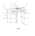
- a wall 1 of a vehicle is equipped with a trellis 3 (partially shown) supporting a shielding plate 2.
- the trellis comprises a substantially horizontal upper bar 3 placed at a distance from the wall 1 through 4
- the trellis also comprises at least one other bar (not shown) parallel to the upper bar and on which the armor plate will bear and can be fixed.
- the armor plate 2 is secured to a support plate 6 by means of screws 8.
- the assembly (called over-protection plate 30) which is formed by the support plate 6 and the armor plate 2 is made integral by the screws 8.
- a single plate can act as a support plate 6 and shielding plate 2.
- An attachment means 7 equips the device 20 in its upper part.
- the hook 7 has a bore 10a in which slides a guide pin 10.
- the pin 10 is integral with the over-protective plate 30.
- the attachment means 7 comprises two threads 11a in which are taken the threads of two screws 11 whose heads are resting on the shielding plate 2.
- the attachment means 7 has a parallelepipedal shape extended by a tongue 7b forming a jaw and it slides in a corresponding opening 7a in the support plate 6.
- the action of screwing or unscrewing the screws 11 causes a approaching or moving the jaw 7b away from the support plate 6.
- fixing screws 12 substantially at the same level as the bottom of the hook 7, these screws are intended to secure the over-protection plate 30 with the upper bar 3 (not visible in this figure).
- the over-protector plate 30 is placed on the horizontal bar 3 of the mesh.
- the hook 7 is supported by its underside on the bar 3.
- the screwing of the screws 11 causes the clamping of the bar 3 by the jaw 7a of the hook 7.
- the plate 30 is firmly held in the lattice leaving all freedom to operators to proceed to the fixing operation of the over-protection plate 30.
- the bar 3 carries tappings evenly spaced from each other (spacing equal to that separating the fastening screws 12 of the overprotective plate).
- the plate 30 has been positioned so that one of the screws 12 is opposite a tapping.
- the fastening screws 12 (not visible on the figure 3 ) penetrate into the corresponding threads (not visible) of the bar 3.
- other fixing screws 12 penetrate into other threads made in another bar 3 of the mesh.
- the trellis is fixed to the vehicle 1 by using any holes 15 ( figure 1 ) or previously existing interfacing bosses for conventional fixation of over-protection elements.
Landscapes
- Engineering & Computer Science (AREA)
- General Engineering & Computer Science (AREA)
- Aiming, Guidance, Guns With A Light Source, Armor, Camouflage, And Targets (AREA)
- Vehicle Interior And Exterior Ornaments, Soundproofing, And Insulation (AREA)
- Vehicle Waterproofing, Decoration, And Sanitation Devices (AREA)
Abstract
Description
- Le domaine technique de l'invention est celui des dispositifs de protection balistique amovibles.
- Les véhicules blindés actuels ont souvent recours à des niveaux de protection balistique variables suivant l'importance des menaces encourues dans les zones où ils circulent.
- Classiquement des plaques de blindages sont appliquées sur les parois des véhicules ou mieux encore sur un treillis métallique placé à distance de la paroi tel que le certificat d'invention statutaire USH129 le décrit. Ce dernier dispositif permet de changer facilement les plaques ayant subi des déformations consécutives à une agression. En effet les déformations des plaques n'interfèrent pas avec les parois du véhicule. Ces plaques de blindage sont fixées par des vis qui pénètrent dans des cavaliers, ces cavaliers enfourchant la structure du treillis. La mise en place, même par plusieurs personnes, des plaques de blindage est extrêmement délicate du fait de leur masse importante souvent supérieure à 40kg et du fait du peu de prise qu'elles offrent. Le risque de chute des plaques est important, occasionnant une détérioration des plaques, des risques d'écrasement des opérateurs d'installation, voire de détérioration des zones d'interfaçage sur le véhicule ou sur le treillis. En outre les vis de fixation sont sollicitées en traction pour maintenir plaquées les plaques de protection sur le treillis mais elles sont également sollicitées en cisaillement par le poids des plaques.
- On connaît aussi par le brevet
DE-2821117 un dispositif d'accrochage de modules de protection balistique au moyen de deux crochets placés en haut et en bas du module. Chaque crochet vient se placer dans une gorge d'un rail solidaire de la structure du véhicule. - On connaît également par le brevet
US2007/0234895 un dispositif d'accrochage de modules de protection balistique comprenant une plaque boulonnée à distance d'une paroi d'un véhicule. Le module de protection est fixé par des vis à la plaque et il est maintenu en position par sa partie basse au moyen d'un ergot venant se caler dans une forme correspondante du bas de la plaque. - Ces deux brevets décrivent des dispositifs qui ne permettent qu'un accrochage temporaire de la plaque de blindage en l'attente d'une fixation définitive du module de protection, par exemple par des vis.
- L'invention se propose de permettre la mise en place des plaques sur un treillis de manière beaucoup plus aisée par l'adjonction d'un moyen d'accrochage sur la face arrière de la plaque. Ce moyen reprendra les efforts dus à la masse, évitant ainsi de solliciter les vis en cisaillement.
- L'invention à pour objet un dispositif de fixation pour au moins une plaque de surprotection, sur une paroi de véhicule, dispositif de fixation comportant au moins deux barres positionnées à distance de la paroi à protéger, dispositif de fixation caractérisé en ce que la barre supérieure comporte au moins une zone horizontale sur laquelle se positionne un moyen d'accrochage solidaire de la plaque de surprotection au niveau de la partie haute de sa face orientée vers le véhicule, la plaque de surprotection étant solidarisée par ailleurs avec au moins une des barres par au moins un moyen de fixation, le moyen d'accrochage comportant une mâchoire pouvant se translater par rapport à la plaque de façon à venir appliquer cette dernière contre la barre.
- Selon un mode réalisation du dispositif, les barres sont fixables aux parois du véhicule en utilisant les moyens de fixation d'éléments de surprotection existants au préalable sur le véhicule.
- Selon un mode de réalisation du dispositif, la plaque de surprotection est rendue solidaire des barres par vissage de la plaque sur les barres.
- Avantageusement, la mâchoire pourra se translater en étant guidée par rapport à la plaque par au moins une goupille, la translation étant commandée par le serrage d'au moins une vis.
- L'invention sera mieux comprise à la lecture du complément de description qui va suivre en relation avec les dessins annexés sur lesquels :
- la
figure 1 représente une vue d'ensemble, orientée depuis l'extérieur d'un véhicule, d'une plaque équipée selon l'invention et placée sur la paroi du véhicule, - la
figure 2 représente une plaque de surprotection vue de trois quarts côté intérieur,et - la
figure 3 représente une vue du dispositif de trois quarts montrant l'interfaçage de la plaque de surprotection avec le treillis. - Selon la
figure 1 , et selon un mode de réalisation, une paroi 1 d'un véhicule est équipée d'un treillis 3 (partiellement représenté) supportant une plaque de blindage 2. Le treillis comporte une barre supérieure 3 sensiblement horizontale placée à distance de la paroi 1 grâce à des entretoises 4 et une équerre de reprise 9. Le treillis comporte également au moins une autre barre (non représentée) parallèle à la barre supérieure et sur laquelle la plaque de blindage viendra en appui et pourra être fixée. - Selon la
figure 2 et selon un mode de réalisation, la plaque de blindage 2 est solidaire d'une plaque support 6 par le biais de vis 8. L'ensemble (nommé plaque de surprotection 30) qui est formé par la plaque support 6 et la plaque de blindage 2 est rendu solidaire par les vis 8. Suivant un autre mode de réalisation, une seule et unique plaque pourra faire office de plaque support 6 et de plaque de blindage 2. Un moyen d'accrochage 7 équipe le dispositif 20 dans sa partie haute. Le crochet 7 comporte un alésage 10a dans lequel coulisse une goupille 10 de guidage. La goupille 10 est solidaire de la plaque de surprotection 30. - Le moyen d'accrochage 7 comporte deux taraudages 11a dans lesquels sont pris les filets de deux vis 11 dont les têtes sont en appui sur la plaque de blindage 2. Le moyen d'accrochage 7 a une forme parallélépipédique prolongée par une languette 7b formant mâchoire et il coulisse dans une ouverture 7a correspondante dans la plaque support 6. L'action de vissage ou dévissage des vis 11 provoque un rapprochement ou un éloignement de la mâchoire 7b vis à vis de la plaque support 6. On notera la présence de vis de fixation 12 sensiblement au même niveau que le bas du crochet 7, ces vis sont destinées à solidariser la plaque de surprotection 30 avec la barre supérieure 3 (non visible sur cette figure).
- Selon la
figure 3 et selon un mode de réalisation, La plaque de surprotection 30 est mise en place sur la barre horizontale 3 du treillis. Le crochet 7 vient en appui par sa face inférieure sur la barre 3. Le vissage des vis 11 provoque le pincement de la barre 3 par la mâchoire 7a du crochet 7. De cette manière la plaque 30 est fermement maintenue au treillis laissant toute liberté aux opérateurs pour passer à l'opération de fixation de la plaque de surprotection 30. - La barre 3 porte des taraudages régulièrement espacés les uns des autres (espacement égal à celui séparant les vis de fixation 12 de la plaque de surprotection). La plaque 30 a été positionnée de telle sorte qu'une des vis 12 se situe en regard d'un taraudage. Les vis de fixation 12 (non visibles sur la
figure 3 ) pénètrent dans les taraudages correspondant (non visibles) de la barre 3. En partie inférieure (partie non visible) de la plaque, d'autres vis de fixation 12 pénètrent dans d'autres taraudages pratiqués dans une autre barre 3 du treillis. - Selon un mode de réalisation, le treillis est fixé au véhicule 1 en utilisant les éventuels trous 15 (
figure 1 ) ou bossages d'interfaçage existant auparavant pour la fixation classique d'éléments de surprotection.
Claims (4)
- Dispositif de fixation pour au moins une plaque de surprotection (30), sur une paroi de véhicule (1), dispositif de fixation comportant au moins deux barres (3) positionnées à distance de la paroi (1) à protéger, dispositif de fixation caractérisé en ce que la barre supérieure (3) comporte au moins une zone horizontale sur laquelle se positionne un moyen d'accrochage (7) solidaire de la plaque de surprotection au niveau de la partie haute de sa face orientée vers le véhicule, la plaque de surprotection (30) étant solidarisée par ailleurs avec au moins une des barres par au moins un moyen de fixation (12), le moyen d'accrochage (7) comportant une mâchoire (7b) pouvant se translater par rapport à la plaque (30) de façon à venir appliquer cette dernière contre la barre (3).
- Dispositif de fixation pour plaque de blindage selon la revendication 1, caractérisé en ce que les barres (3) sont fixables aux parois (1) du véhicule en utilisant les moyens de fixation (15) d'éléments de surprotection existants au préalable sur le véhicule.
- Dispositif de fixation pour plaque de surprotection selon une des revendications 1 ou 2, caractérisé en ce que la plaque de surprotection (30) est rendue solidaire des barres (3) par vissage de la plaque (30) sur les barres (3).
- Dispositif de fixation pour plaque de surprotection selon une des revendications 1 à 3, caractérisé en ce que la mâchoire (7) se translate en étant guidée par rapport à la plaque par au moins une goupille (10), la translation étant commandée par le serrage d'au moins une vis (11).
Priority Applications (1)
| Application Number | Priority Date | Filing Date | Title |
|---|---|---|---|
| PL11290173T PL2381209T3 (pl) | 2010-04-26 | 2011-04-06 | Urządzenie do mocowania nakładanej płyty zabezpieczającej do ściany pojazdu |
Applications Claiming Priority (1)
| Application Number | Priority Date | Filing Date | Title |
|---|---|---|---|
| FR1001783A FR2959302B1 (fr) | 2010-04-26 | 2010-04-26 | Dispositif de fixation pour une plaque de surprotection sur une paroi de vehicule |
Publications (2)
| Publication Number | Publication Date |
|---|---|
| EP2381209A1 true EP2381209A1 (fr) | 2011-10-26 |
| EP2381209B1 EP2381209B1 (fr) | 2013-08-28 |
Family
ID=43242315
Family Applications (1)
| Application Number | Title | Priority Date | Filing Date |
|---|---|---|---|
| EP11290173.1A Active EP2381209B1 (fr) | 2010-04-26 | 2011-04-06 | Dispositif de fixation pour une plaque de surprotection sur une paroi de véhicule |
Country Status (4)
| Country | Link |
|---|---|
| EP (1) | EP2381209B1 (fr) |
| ES (1) | ES2435014T3 (fr) |
| FR (1) | FR2959302B1 (fr) |
| PL (1) | PL2381209T3 (fr) |
Citations (5)
| Publication number | Priority date | Publication date | Assignee | Title |
|---|---|---|---|---|
| USH129H (en) * | 1986-01-29 | 1986-09-02 | The United States Of America As Represented By The Secretary Of The Army | Modular armor support |
| DE2821117C1 (de) | 1978-05-13 | 1988-06-09 | Thyssen Ind Ag Maschb | Anordnung von mindestens einer Schutzplatte mittels einer energieabsorbierenden Halterung aus nichtmetallischem,elastischem Material an/in einem Schutzobjekt |
| DE3931895A1 (de) * | 1989-09-25 | 1994-12-15 | Wegmann & Co Gmbh | Einrichtung zur Anordnung von adaptierbaren Panzerungselementen an gegen Waffeneinwirkung zu schützenden Objekten, insbesondere an Kampffahrzeugen |
| EP0803699A1 (fr) * | 1996-04-23 | 1997-10-29 | Giat Industries | Dispositif de fixation d'un caisson sur une structure |
| US20070234895A1 (en) | 2006-04-10 | 2007-10-11 | Singh Paul P | External modular assembly |
-
2010
- 2010-04-26 FR FR1001783A patent/FR2959302B1/fr not_active Expired - Fee Related
-
2011
- 2011-04-06 ES ES11290173T patent/ES2435014T3/es active Active
- 2011-04-06 EP EP11290173.1A patent/EP2381209B1/fr active Active
- 2011-04-06 PL PL11290173T patent/PL2381209T3/pl unknown
Patent Citations (5)
| Publication number | Priority date | Publication date | Assignee | Title |
|---|---|---|---|---|
| DE2821117C1 (de) | 1978-05-13 | 1988-06-09 | Thyssen Ind Ag Maschb | Anordnung von mindestens einer Schutzplatte mittels einer energieabsorbierenden Halterung aus nichtmetallischem,elastischem Material an/in einem Schutzobjekt |
| USH129H (en) * | 1986-01-29 | 1986-09-02 | The United States Of America As Represented By The Secretary Of The Army | Modular armor support |
| DE3931895A1 (de) * | 1989-09-25 | 1994-12-15 | Wegmann & Co Gmbh | Einrichtung zur Anordnung von adaptierbaren Panzerungselementen an gegen Waffeneinwirkung zu schützenden Objekten, insbesondere an Kampffahrzeugen |
| EP0803699A1 (fr) * | 1996-04-23 | 1997-10-29 | Giat Industries | Dispositif de fixation d'un caisson sur une structure |
| US20070234895A1 (en) | 2006-04-10 | 2007-10-11 | Singh Paul P | External modular assembly |
Also Published As
| Publication number | Publication date |
|---|---|
| EP2381209B1 (fr) | 2013-08-28 |
| ES2435014T3 (es) | 2013-12-18 |
| FR2959302B1 (fr) | 2013-01-04 |
| PL2381209T3 (pl) | 2014-01-31 |
| FR2959302A1 (fr) | 2011-10-28 |
Similar Documents
| Publication | Publication Date | Title |
|---|---|---|
| US9543558B2 (en) | Battery holder and isolation assembly | |
| US20120012731A1 (en) | Fastenerless Engine Exhaust Component Suspension Device | |
| US8844778B2 (en) | Adapter bracket for supporting a saddle bag on a motorcycle and method for installing same | |
| FR2897468A1 (fr) | Dispositif de contact auxiliaire pour contacteur magnetique | |
| EP2318588B1 (fr) | Dispositif de fixation de rail sur un support de voie | |
| EP2381209B1 (fr) | Dispositif de fixation pour une plaque de surprotection sur une paroi de véhicule | |
| FR3004844A1 (fr) | Dispositif d'etiquetage electronique | |
| US8499989B1 (en) | Motorcycle mounted helmet carrier | |
| AU2014206961B2 (en) | Supporting frame with mesh floor for racks | |
| US20100164199A1 (en) | Auxiliary Frame | |
| EP2098410A1 (fr) | Dispositif de galerie intérieure pour véhicule automobile, et véhicule automobile correspondant | |
| MA37517B1 (fr) | Panneau photovoltaïque à haute concentration | |
| JP2014045611A (ja) | 架空線ダンパ保護装置 | |
| FR2772411A1 (fr) | Systeme de protection contre la chute d'objets | |
| US20140217346A1 (en) | Support for a roof hatch rail | |
| US20170167657A1 (en) | Adjustable Hanging System and Method | |
| EP2962560B1 (fr) | Dispositif anti-prédation pour bassin piscicole | |
| FR3030378A1 (fr) | Dispositif anti-bourdonnement pour porte de coffre. | |
| FR2636822A1 (fr) | Table comprenant des moyens de fixation d'un caisson a un plateau | |
| FR2982350A1 (fr) | Dispositif de fixation d'un element photovoltaique | |
| WO2015015066A1 (fr) | Support d'enrouleur de ceinture de sécurite destiné à être fixé à l'un des deux longerons interieurs d'un vehicule automobile | |
| FR3075845A1 (fr) | Dispositif de rangement d'une planche a roulettes | |
| JP4295240B2 (ja) | 側溝蓋および、側溝蓋に用いられる蓋体 | |
| FR3077835A1 (fr) | Panneau grillage | |
| FR2849681A1 (fr) | Dispositif de fixation pour le montage d'elements dans un espace restreint |
Legal Events
| Date | Code | Title | Description |
|---|---|---|---|
| AK | Designated contracting states |
Kind code of ref document: A1 Designated state(s): AL AT BE BG CH CY CZ DE DK EE ES FI FR GB GR HR HU IE IS IT LI LT LU LV MC MK MT NL NO PL PT RO RS SE SI SK SM TR |
|
| AX | Request for extension of the european patent |
Extension state: BA ME |
|
| PUAI | Public reference made under article 153(3) epc to a published international application that has entered the european phase |
Free format text: ORIGINAL CODE: 0009012 |
|
| 17P | Request for examination filed |
Effective date: 20120418 |
|
| GRAP | Despatch of communication of intention to grant a patent |
Free format text: ORIGINAL CODE: EPIDOSNIGR1 |
|
| RIC1 | Information provided on ipc code assigned before grant |
Ipc: F41H 7/04 20060101ALI20130225BHEP Ipc: F41H 5/02 20060101ALI20130225BHEP Ipc: F41H 5/013 20060101AFI20130225BHEP |
|
| GRAS | Grant fee paid |
Free format text: ORIGINAL CODE: EPIDOSNIGR3 |
|
| GRAA | (expected) grant |
Free format text: ORIGINAL CODE: 0009210 |
|
| AK | Designated contracting states |
Kind code of ref document: B1 Designated state(s): AL AT BE BG CH CY CZ DE DK EE ES FI FR GB GR HR HU IE IS IT LI LT LU LV MC MK MT NL NO PL PT RO RS SE SI SK SM TR |
|
| REG | Reference to a national code |
Ref country code: GB Ref legal event code: FG4D Free format text: NOT ENGLISH |
|
| REG | Reference to a national code |
Ref country code: CH Ref legal event code: EP |
|
| REG | Reference to a national code |
Ref country code: AT Ref legal event code: REF Ref document number: 629591 Country of ref document: AT Kind code of ref document: T Effective date: 20130915 |
|
| REG | Reference to a national code |
Ref country code: IE Ref legal event code: FG4D Free format text: LANGUAGE OF EP DOCUMENT: FRENCH |
|
| REG | Reference to a national code |
Ref country code: DE Ref legal event code: R096 Ref document number: 602011002842 Country of ref document: DE Effective date: 20131024 |
|
| REG | Reference to a national code |
Ref country code: SE Ref legal event code: TRGR |
|
| REG | Reference to a national code |
Ref country code: ES Ref legal event code: FG2A Ref document number: 2435014 Country of ref document: ES Kind code of ref document: T3 Effective date: 20131218 |
|
| REG | Reference to a national code |
Ref country code: AT Ref legal event code: MK05 Ref document number: 629591 Country of ref document: AT Kind code of ref document: T Effective date: 20130828 |
|
| REG | Reference to a national code |
Ref country code: LT Ref legal event code: MG4D |
|
| REG | Reference to a national code |
Ref country code: NL Ref legal event code: VDEP Effective date: 20130828 |
|
| PG25 | Lapsed in a contracting state [announced via postgrant information from national office to epo] |
Ref country code: PT Free format text: LAPSE BECAUSE OF FAILURE TO SUBMIT A TRANSLATION OF THE DESCRIPTION OR TO PAY THE FEE WITHIN THE PRESCRIBED TIME-LIMIT Effective date: 20131230 Ref country code: CY Free format text: LAPSE BECAUSE OF FAILURE TO SUBMIT A TRANSLATION OF THE DESCRIPTION OR TO PAY THE FEE WITHIN THE PRESCRIBED TIME-LIMIT Effective date: 20130724 Ref country code: LT Free format text: LAPSE BECAUSE OF FAILURE TO SUBMIT A TRANSLATION OF THE DESCRIPTION OR TO PAY THE FEE WITHIN THE PRESCRIBED TIME-LIMIT Effective date: 20130828 Ref country code: AT Free format text: LAPSE BECAUSE OF FAILURE TO SUBMIT A TRANSLATION OF THE DESCRIPTION OR TO PAY THE FEE WITHIN THE PRESCRIBED TIME-LIMIT Effective date: 20130828 Ref country code: HR Free format text: LAPSE BECAUSE OF FAILURE TO SUBMIT A TRANSLATION OF THE DESCRIPTION OR TO PAY THE FEE WITHIN THE PRESCRIBED TIME-LIMIT Effective date: 20130828 Ref country code: NO Free format text: LAPSE BECAUSE OF FAILURE TO SUBMIT A TRANSLATION OF THE DESCRIPTION OR TO PAY THE FEE WITHIN THE PRESCRIBED TIME-LIMIT Effective date: 20131128 Ref country code: IS Free format text: LAPSE BECAUSE OF FAILURE TO SUBMIT A TRANSLATION OF THE DESCRIPTION OR TO PAY THE FEE WITHIN THE PRESCRIBED TIME-LIMIT Effective date: 20131228 |
|
| REG | Reference to a national code |
Ref country code: PL Ref legal event code: T3 |
|
| REG | Reference to a national code |
Ref country code: NL Ref legal event code: VDEP Effective date: 20130828 |
|
| PG25 | Lapsed in a contracting state [announced via postgrant information from national office to epo] |
Ref country code: SI Free format text: LAPSE BECAUSE OF FAILURE TO SUBMIT A TRANSLATION OF THE DESCRIPTION OR TO PAY THE FEE WITHIN THE PRESCRIBED TIME-LIMIT Effective date: 20130828 Ref country code: LV Free format text: LAPSE BECAUSE OF FAILURE TO SUBMIT A TRANSLATION OF THE DESCRIPTION OR TO PAY THE FEE WITHIN THE PRESCRIBED TIME-LIMIT Effective date: 20130828 Ref country code: GR Free format text: LAPSE BECAUSE OF FAILURE TO SUBMIT A TRANSLATION OF THE DESCRIPTION OR TO PAY THE FEE WITHIN THE PRESCRIBED TIME-LIMIT Effective date: 20131129 |
|
| PG25 | Lapsed in a contracting state [announced via postgrant information from national office to epo] |
Ref country code: CY Free format text: LAPSE BECAUSE OF FAILURE TO SUBMIT A TRANSLATION OF THE DESCRIPTION OR TO PAY THE FEE WITHIN THE PRESCRIBED TIME-LIMIT Effective date: 20130828 |
|
| PG25 | Lapsed in a contracting state [announced via postgrant information from national office to epo] |
Ref country code: SK Free format text: LAPSE BECAUSE OF FAILURE TO SUBMIT A TRANSLATION OF THE DESCRIPTION OR TO PAY THE FEE WITHIN THE PRESCRIBED TIME-LIMIT Effective date: 20130828 Ref country code: NL Free format text: LAPSE BECAUSE OF FAILURE TO SUBMIT A TRANSLATION OF THE DESCRIPTION OR TO PAY THE FEE WITHIN THE PRESCRIBED TIME-LIMIT Effective date: 20130828 Ref country code: EE Free format text: LAPSE BECAUSE OF FAILURE TO SUBMIT A TRANSLATION OF THE DESCRIPTION OR TO PAY THE FEE WITHIN THE PRESCRIBED TIME-LIMIT Effective date: 20130828 Ref country code: RO Free format text: LAPSE BECAUSE OF FAILURE TO SUBMIT A TRANSLATION OF THE DESCRIPTION OR TO PAY THE FEE WITHIN THE PRESCRIBED TIME-LIMIT Effective date: 20130828 Ref country code: CZ Free format text: LAPSE BECAUSE OF FAILURE TO SUBMIT A TRANSLATION OF THE DESCRIPTION OR TO PAY THE FEE WITHIN THE PRESCRIBED TIME-LIMIT Effective date: 20130828 Ref country code: DK Free format text: LAPSE BECAUSE OF FAILURE TO SUBMIT A TRANSLATION OF THE DESCRIPTION OR TO PAY THE FEE WITHIN THE PRESCRIBED TIME-LIMIT Effective date: 20130828 |
|
| REG | Reference to a national code |
Ref country code: DE Ref legal event code: R097 Ref document number: 602011002842 Country of ref document: DE |
|
| PLBE | No opposition filed within time limit |
Free format text: ORIGINAL CODE: 0009261 |
|
| STAA | Information on the status of an ep patent application or granted ep patent |
Free format text: STATUS: NO OPPOSITION FILED WITHIN TIME LIMIT |
|
| 26N | No opposition filed |
Effective date: 20140530 |
|
| REG | Reference to a national code |
Ref country code: DE Ref legal event code: R097 Ref document number: 602011002842 Country of ref document: DE Effective date: 20140530 |
|
| PG25 | Lapsed in a contracting state [announced via postgrant information from national office to epo] |
Ref country code: LU Free format text: LAPSE BECAUSE OF FAILURE TO SUBMIT A TRANSLATION OF THE DESCRIPTION OR TO PAY THE FEE WITHIN THE PRESCRIBED TIME-LIMIT Effective date: 20140406 Ref country code: MC Free format text: LAPSE BECAUSE OF FAILURE TO SUBMIT A TRANSLATION OF THE DESCRIPTION OR TO PAY THE FEE WITHIN THE PRESCRIBED TIME-LIMIT Effective date: 20130828 |
|
| REG | Reference to a national code |
Ref country code: IE Ref legal event code: MM4A |
|
| PG25 | Lapsed in a contracting state [announced via postgrant information from national office to epo] |
Ref country code: IE Free format text: LAPSE BECAUSE OF NON-PAYMENT OF DUE FEES Effective date: 20140406 |
|
| PG25 | Lapsed in a contracting state [announced via postgrant information from national office to epo] |
Ref country code: MT Free format text: LAPSE BECAUSE OF FAILURE TO SUBMIT A TRANSLATION OF THE DESCRIPTION OR TO PAY THE FEE WITHIN THE PRESCRIBED TIME-LIMIT Effective date: 20130828 |
|
| REG | Reference to a national code |
Ref country code: FR Ref legal event code: PLFP Year of fee payment: 6 |
|
| PG25 | Lapsed in a contracting state [announced via postgrant information from national office to epo] |
Ref country code: SM Free format text: LAPSE BECAUSE OF FAILURE TO SUBMIT A TRANSLATION OF THE DESCRIPTION OR TO PAY THE FEE WITHIN THE PRESCRIBED TIME-LIMIT Effective date: 20130828 |
|
| PG25 | Lapsed in a contracting state [announced via postgrant information from national office to epo] |
Ref country code: BG Free format text: LAPSE BECAUSE OF FAILURE TO SUBMIT A TRANSLATION OF THE DESCRIPTION OR TO PAY THE FEE WITHIN THE PRESCRIBED TIME-LIMIT Effective date: 20130828 Ref country code: RS Free format text: LAPSE BECAUSE OF NON-PAYMENT OF DUE FEES Effective date: 20130828 |
|
| PG25 | Lapsed in a contracting state [announced via postgrant information from national office to epo] |
Ref country code: HU Free format text: LAPSE BECAUSE OF FAILURE TO SUBMIT A TRANSLATION OF THE DESCRIPTION OR TO PAY THE FEE WITHIN THE PRESCRIBED TIME-LIMIT; INVALID AB INITIO Effective date: 20110406 Ref country code: BE Free format text: LAPSE BECAUSE OF FAILURE TO SUBMIT A TRANSLATION OF THE DESCRIPTION OR TO PAY THE FEE WITHIN THE PRESCRIBED TIME-LIMIT Effective date: 20140430 |
|
| REG | Reference to a national code |
Ref country code: FR Ref legal event code: PLFP Year of fee payment: 7 |
|
| REG | Reference to a national code |
Ref country code: FR Ref legal event code: PLFP Year of fee payment: 8 |
|
| PG25 | Lapsed in a contracting state [announced via postgrant information from national office to epo] |
Ref country code: MK Free format text: LAPSE BECAUSE OF FAILURE TO SUBMIT A TRANSLATION OF THE DESCRIPTION OR TO PAY THE FEE WITHIN THE PRESCRIBED TIME-LIMIT Effective date: 20130828 |
|
| PG25 | Lapsed in a contracting state [announced via postgrant information from national office to epo] |
Ref country code: AL Free format text: LAPSE BECAUSE OF FAILURE TO SUBMIT A TRANSLATION OF THE DESCRIPTION OR TO PAY THE FEE WITHIN THE PRESCRIBED TIME-LIMIT Effective date: 20130828 |
|
| PGFP | Annual fee paid to national office [announced via postgrant information from national office to epo] |
Ref country code: DE Payment date: 20250319 Year of fee payment: 15 |
|
| PGFP | Annual fee paid to national office [announced via postgrant information from national office to epo] |
Ref country code: ES Payment date: 20250502 Year of fee payment: 15 |
|
| PGFP | Annual fee paid to national office [announced via postgrant information from national office to epo] |
Ref country code: CH Payment date: 20250501 Year of fee payment: 15 |
|
| PGFP | Annual fee paid to national office [announced via postgrant information from national office to epo] |
Ref country code: SE Payment date: 20260319 Year of fee payment: 16 |
|
| PGFP | Annual fee paid to national office [announced via postgrant information from national office to epo] |
Ref country code: GB Payment date: 20260319 Year of fee payment: 16 |
|
| PGFP | Annual fee paid to national office [announced via postgrant information from national office to epo] |
Ref country code: FI Payment date: 20260319 Year of fee payment: 16 Ref country code: IT Payment date: 20260319 Year of fee payment: 16 |
|
| PGFP | Annual fee paid to national office [announced via postgrant information from national office to epo] |
Ref country code: FR Payment date: 20260319 Year of fee payment: 16 |
|
| PGFP | Annual fee paid to national office [announced via postgrant information from national office to epo] |
Ref country code: TR Payment date: 20260327 Year of fee payment: 16 |
|
| PGFP | Annual fee paid to national office [announced via postgrant information from national office to epo] |
Ref country code: PL Payment date: 20260325 Year of fee payment: 16 |
|
| REG | Reference to a national code |
Ref country code: CH Ref legal event code: U11 Free format text: ST27 STATUS EVENT CODE: U-0-0-U10-U11 (AS PROVIDED BY THE NATIONAL OFFICE) Effective date: 20260501 |