EP2380856A2 - Burner for producing porous glass preform - Google Patents
Burner for producing porous glass preform Download PDFInfo
- Publication number
- EP2380856A2 EP2380856A2 EP11163597A EP11163597A EP2380856A2 EP 2380856 A2 EP2380856 A2 EP 2380856A2 EP 11163597 A EP11163597 A EP 11163597A EP 11163597 A EP11163597 A EP 11163597A EP 2380856 A2 EP2380856 A2 EP 2380856A2
- Authority
- EP
- European Patent Office
- Prior art keywords
- gas jet
- burner
- diameter
- jet ports
- tube
- Prior art date
- Legal status (The legal status is an assumption and is not a legal conclusion. Google has not performed a legal analysis and makes no representation as to the accuracy of the status listed.)
- Granted
Links
- 239000005373 porous glass Substances 0.000 title claims abstract description 16
- 239000011521 glass Substances 0.000 claims abstract description 27
- 239000000463 material Substances 0.000 claims abstract description 15
- 238000004519 manufacturing process Methods 0.000 claims description 3
- 230000008021 deposition Effects 0.000 abstract description 12
- 239000007789 gas Substances 0.000 description 86
- 238000009826 distribution Methods 0.000 description 16
- 238000000151 deposition Methods 0.000 description 12
- 230000000052 comparative effect Effects 0.000 description 8
- 239000013307 optical fiber Substances 0.000 description 8
- 238000000034 method Methods 0.000 description 6
- 230000002194 synthesizing effect Effects 0.000 description 5
- 239000004071 soot Substances 0.000 description 4
- 230000005856 abnormality Effects 0.000 description 2
- 238000010586 diagram Methods 0.000 description 2
- 239000011261 inert gas Substances 0.000 description 2
- 238000005457 optimization Methods 0.000 description 2
- MYMOFIZGZYHOMD-UHFFFAOYSA-N Dioxygen Chemical compound O=O MYMOFIZGZYHOMD-UHFFFAOYSA-N 0.000 description 1
- UFHFLCQGNIYNRP-UHFFFAOYSA-N Hydrogen Chemical compound [H][H] UFHFLCQGNIYNRP-UHFFFAOYSA-N 0.000 description 1
- VYPSYNLAJGMNEJ-UHFFFAOYSA-N Silicium dioxide Chemical compound O=[Si]=O VYPSYNLAJGMNEJ-UHFFFAOYSA-N 0.000 description 1
- 238000006243 chemical reaction Methods 0.000 description 1
- 239000000567 combustion gas Substances 0.000 description 1
- 238000011109 contamination Methods 0.000 description 1
- 230000003247 decreasing effect Effects 0.000 description 1
- 238000004031 devitrification Methods 0.000 description 1
- 229910001882 dioxygen Inorganic materials 0.000 description 1
- 238000010438 heat treatment Methods 0.000 description 1
- 230000007062 hydrolysis Effects 0.000 description 1
- 238000006460 hydrolysis reaction Methods 0.000 description 1
- 238000005259 measurement Methods 0.000 description 1
- 239000012495 reaction gas Substances 0.000 description 1
- 238000007789 sealing Methods 0.000 description 1
- 238000005245 sintering Methods 0.000 description 1
- 238000007740 vapor deposition Methods 0.000 description 1
Images

Classifications
-
- C—CHEMISTRY; METALLURGY
- C03—GLASS; MINERAL OR SLAG WOOL
- C03B—MANUFACTURE, SHAPING, OR SUPPLEMENTARY PROCESSES
- C03B37/00—Manufacture or treatment of flakes, fibres, or filaments from softened glass, minerals, or slags
- C03B37/01—Manufacture of glass fibres or filaments
- C03B37/012—Manufacture of preforms for drawing fibres or filaments
- C03B37/014—Manufacture of preforms for drawing fibres or filaments made entirely or partially by chemical means, e.g. vapour phase deposition of bulk porous glass either by outside vapour deposition [OVD], or by outside vapour phase oxidation [OVPO] or by vapour axial deposition [VAD]
- C03B37/01413—Reactant delivery systems
- C03B37/0142—Reactant deposition burners
-
- C—CHEMISTRY; METALLURGY
- C03—GLASS; MINERAL OR SLAG WOOL
- C03B—MANUFACTURE, SHAPING, OR SUPPLEMENTARY PROCESSES
- C03B2207/00—Glass deposition burners
- C03B2207/04—Multi-nested ports
- C03B2207/06—Concentric circular ports
-
- C—CHEMISTRY; METALLURGY
- C03—GLASS; MINERAL OR SLAG WOOL
- C03B—MANUFACTURE, SHAPING, OR SUPPLEMENTARY PROCESSES
- C03B2207/00—Glass deposition burners
- C03B2207/04—Multi-nested ports
- C03B2207/12—Nozzle or orifice plates
-
- C—CHEMISTRY; METALLURGY
- C03—GLASS; MINERAL OR SLAG WOOL
- C03B—MANUFACTURE, SHAPING, OR SUPPLEMENTARY PROCESSES
- C03B2207/00—Glass deposition burners
- C03B2207/04—Multi-nested ports
- C03B2207/14—Tapered or flared nozzles or ports angled to central burner axis
-
- C—CHEMISTRY; METALLURGY
- C03—GLASS; MINERAL OR SLAG WOOL
- C03B—MANUFACTURE, SHAPING, OR SUPPLEMENTARY PROCESSES
- C03B2207/00—Glass deposition burners
- C03B2207/04—Multi-nested ports
- C03B2207/18—Eccentric ports
-
- C—CHEMISTRY; METALLURGY
- C03—GLASS; MINERAL OR SLAG WOOL
- C03B—MANUFACTURE, SHAPING, OR SUPPLEMENTARY PROCESSES
- C03B2207/00—Glass deposition burners
- C03B2207/20—Specific substances in specified ports, e.g. all gas flows specified
-
- C—CHEMISTRY; METALLURGY
- C03—GLASS; MINERAL OR SLAG WOOL
- C03B—MANUFACTURE, SHAPING, OR SUPPLEMENTARY PROCESSES
- C03B2207/00—Glass deposition burners
- C03B2207/42—Assembly details; Material or dimensions of burner; Manifolds or supports
Definitions
- the present invention relates to a burner for producing a porous glass preform, having a multi-nozzle type concentric multi-tube structure in which multiple gas jet ports are disposed concentrically.
- the outside vapor deposition method (OVD method) is generally used since the refractive-index distribution of an optical fiber preform to be obtained can be set relatively freely, and moreover optical fiber preforms with large diameters can be mass-produced.
- the OVD method includes depositing and attaching glass particulates generated in a flame of a burner onto a rotating starting member by relatively reciprocating the burner or the starting member, so as to synthesize a glass particulate deposition (hereinafter, referred to as "soot"), and dehydrating and sintering the resultant soot in an electric furnace to produce a transparent glass body.
- a concentric multi-tube burner has been used for synthesizing the soot.
- Such a structure of the burner does not allow glass material gas, combustible gas, and combustion-supporting gas to be mixed well, so that glass particulates are not produced sufficiently.
- the yield of the glass particulates is not satisfactory, thereby causing difficulties in synthesizing them at high speed.
- JP-B Japanese Patent
- JP-B No. 1773359 proposes a multi-nozzle type burner in which small-diameter combustion-supporting gas jet ports are disposed in a combustible gas jet port to surround a material gas jet port arranged in a center of the burner.
- JP-A Japanese Patent Application Publication
- JP-A No. 2003-206154 JP-A No. 2004-331440 , JP-A No. 2006-182624 , and JP-B No. 3744350 , for example, propose configurations of the small-diameter combustion-supporting gas jet ports.
- JP-A No. Hei 05-323130 JP-B No. 3543537
- JP-A No. 2003-226544 for example, propose optimization of focal lengths of the small-diameter combustion-supporting gas jet ports.
- Japanese Patent No. 3591330 , JP-A No. 2003-165737 , JP-A No. 2003-212555 , and Japanese Patent No. 3653902 propose optimization of a gas flow rate and a gas linear velocity.
- the burner for producing a porous glass preform is generally made of silica glass to prevent contamination, and is manually fabricated by a glass blower.
- the multi-nozzle type burner has a more complex structure than a conventional concentric multi-tube burner and, specifically, it is highly difficult to fabricate the multi-nozzle type burner having a configuration in which multiple gas jet ports are arranged outside the small-diameter gas jet port and are reduced in their diameters at the tip side.
- the multi-nozzle type burner having such a complex structure is fabricated by a skilled glass blower with satisfactory attention to precision, individual differences of the burners tend to be larger than a conventional concentric multi-tube burner. Such individual differences of the burners result from tolerance stack-up of members.
- An object of the invention is to provide a multi-nozzle type burner for producing a porous glass preform, the burner having small variations in deposition efficiency with the burner tip being not burned even when axial shift occurs at the concentric multi-tube part of the burner.
- a burner for producing a porous glass preform with a concentric multi-tube structure includes a glass material gas jet port in a center; a plurality of gas jet ports concentrically disposed outside the glass material gas jet port; and small-diameter gas jet ports which are disposed in a line or a plurality of lines concentrically to the glass material gas jet port so as to be enclosed in one of the gas jet ports other than the gas jet ports in the center and at an outermost side, the small-diameter gas jet ports in the same line having an identical focal length.
- the gas jet ports disposed outside the gas jet port enclosing the small-diameter gas jet ports are each reduced in diameter in a direction toward a burner tip, and satisfy a relationship of L1>L2>L3>... >Ln, where L1, L2, L3, ... Ln represent lengths from the burner tip to diameter-reduction start positions of the outside-disposed gas jet ports in this order from the inside, respectively, so that the more outward the gas jet port is located, the closer to the burner tip the diameter-reduction start position of the gas jet port is.
- a method for producing a porous glass preform is a production method using the burner for producing a porous glass preform.
- the tubes are reduced in diameter toward the tip sequentially from the inside to the outside, so that the diameter-reduction start positions are shifted sequentially, thereby preventing clearance of a gas flow path from being extremely small.
- Table 1 shows a clearance comparison between cases of large clearance and small clearance, where the inner tubes are the same, and the outer tube axial shift amounts are commonly 0.5 mm. Even with the same axial shift amount, a smaller absolute amount of clearance results in a larger clearance ratio (b/a), whereas a larger absolute amount of clearance results in a smaller clearance ratio (b/a), thereby allowing influence of the axial shift to be reduced relatively. As a result, a smaller absolute amount of clearance leads to great varieties in linear velocity distribution.
- Table 1 Small clearance Large clearance Inner tube diameter mm 30 30 Outer tube diameter mm 32 38 Average clearance mm 1.0 4.0 Minimum clearance (a) mm 0.5 3.5 Maximum clearance (b) mm 1.5 4.5 Clearance ratio (b/a) - 3 1.3
- the diameter-reduction start position of the outer tube was, in fact, slightly further from the tip than that of the inner tube, although the diameter of each tube is supposed to be reduced at the same position.
- the outer tube was reduced in diameter first to be close to the inner tube, thereby resulting in smaller clearance than the designed clearance.
- Ln represent lengths from the burner tip to diameter-reduction start positions of the outside-disposed gas jet ports in this order from the inside, respectively, so that the more outward the gas jet port is located, the closer to the burner tip the diameter-reduction start position of the gas jet port is.
- a starting member is welded with dummy rods 2 at both ends of a core rod 1, and rotatably supported by a chuck mechanism 4 about an axis.
- a burner 3 is configured to laterally move, and is disposed to face the starting member.
- Optical fiber materials e.g. vapor of SiCI 4 or the like and combustion gas (hydrogen gas and oxygen gas) are sprayed with the burner 3 to the starting member to deposit on the starting member glass particulates (soot) generated by hydrolysis in an oxyhydrogen flame.
- a deposition layer is formed by reciprocating the burner 3 in the longitudinal direction of the starting member with a burner guide mechanism (not shown), thereby providing a porous glass preform for optical fiber.
- a mechanism may be employed in which the starting member is reciprocated in the longitudinal direction instead of the burner 3.
- porous glass preform for optical fiber is dehydrated in a heating furnace, and then converted to a transparent glass to be a glass preform for optical fiber.
- a burner 3 for producing a porous glass preform includes a first tube of a glass material gas jet port 6 in a center, a second tube of a seal gas jet port 7, a third tube of a combustible gas jet port 8 enclosing eight small-diameter combustion-supporting gas jet ports 11 having a focal length of 150 mm, a fourth tube of a seal gas jet port 9, and a fifth tube of a combustion-supporting gas jet port 10.
- the tips of the third tube 8, the fourth tube 9, and the fifth tube 10 are reduced in diameter as shown in Fig. 3 .
- the fourth tube 9 was axially shifted by 0.5 mm relative to the third tube 8
- the fifth tube 10 was axially shifted by 0.5 mm relative to the fourth tube 9.
- the fourth 9 and the fifth 10 tubes were axially shifted in such a direction that the clearances can be smaller on a side in which the gas inlet 12 tubes of the gas jet ports were disposed.
- the burner 3 used in Examples 1 and 2, as shown in Fig. 3 , has a structure in which a tube arranged more outward from the small-diameter gas jet ports 11 has a diameter reduced at a position closer to the burner tip (L1>L2>L3).
- the burner used in Comparative Examples 1 and 2, as shown in Fig. 5 has a structure in which a tube arranged more outward from the small-diameter gas jet ports 11 has a diameter reduced at a position more away from the burner tip (L1 ⁇ L2 ⁇ L3).
- the fourth tube 9 was supplied with N 2 as a seal gas at 5 L/min, and the fifth tube 10 was supplied with O 2 as a combustion-supporting gas at 40 L/min.
- Example 1 Example 2 Comparative Example 1 Comparative Example 2 mm mm mm mm Diameter-reduction position of third tube 8 L3 70 70 70 Diameter-reduction position of fourth tube 9 L4 60 65 75 80 diameter-reduction position of fifth tube 10 L5 50 60 80 90
- the linear velocity distribution was measured at 90 degree intervals in four directions, i.e. zero o'clock, three o'clock, six o'clock, and nine o'clock directions.
- the direction in which the gas inlet 12 tubes of the gas jet ports are disposed is defined as the zero o'clock direction.
- the first tube 6 was supplied with SiCI 4 as a glass material gas at 10 L/min and with O 2 as a combustion-supporting gas at 20 L/min
- the second tube 7 was supplied with N 2 as a seal gas at 4 L/min
- the third tube 8 was supplied with H 2 as a combustible gas at 170 L/min
- the fourth tube 9 was supplied with N 2 as a seal gas at 5 L/min
- the fifth tube 10 was supplied with O 2 as a combustion-supporting at 40 L/min
- the small-diameter gas jet ports 11 were supplied with O 2 as a combustion-supporting gas at 16 L/min.
Landscapes
- Chemical & Material Sciences (AREA)
- Engineering & Computer Science (AREA)
- Geochemistry & Mineralogy (AREA)
- Life Sciences & Earth Sciences (AREA)
- General Chemical & Material Sciences (AREA)
- General Life Sciences & Earth Sciences (AREA)
- Chemical Kinetics & Catalysis (AREA)
- Manufacturing & Machinery (AREA)
- Materials Engineering (AREA)
- Organic Chemistry (AREA)
- Glass Melting And Manufacturing (AREA)
- Manufacture, Treatment Of Glass Fibers (AREA)
- Gas Burners (AREA)
Abstract
Description
- The present invention relates to a burner for producing a porous glass preform, having a multi-nozzle type concentric multi-tube structure in which multiple gas jet ports are disposed concentrically.
- Conventionally, various methods have been proposed to produce an optical fiber preform. Among them, the outside vapor deposition method (OVD method) is generally used since the refractive-index distribution of an optical fiber preform to be obtained can be set relatively freely, and moreover optical fiber preforms with large diameters can be mass-produced. The OVD method includes depositing and attaching glass particulates generated in a flame of a burner onto a rotating starting member by relatively reciprocating the burner or the starting member, so as to synthesize a glass particulate deposition (hereinafter, referred to as "soot"), and dehydrating and sintering the resultant soot in an electric furnace to produce a transparent glass body.
- Conventionally, a concentric multi-tube burner has been used for synthesizing the soot. Such a structure of the burner does not allow glass material gas, combustible gas, and combustion-supporting gas to be mixed well, so that glass particulates are not produced sufficiently. As a result, the yield of the glass particulates is not satisfactory, thereby causing difficulties in synthesizing them at high speed.
- To solve the above problem, Japanese Patent (JP-B) No.
1773359 - Moreover, the following methods have been proposed to further improve deposition efficiency with this type of burner.
- Japanese Patent Application Publication (JP-A) No.
2003-206154 JP-A No. 2004-331440 JP-A No. 2006-182624 JP-B No. 3744350 JP-A No. Hei 05-323130 JP-B No. 3543537 JP-A No. 2003-226544 3591330 JP-A No. 2003-165737 JP-A No. 2003-212555 3653902 - The burner for producing a porous glass preform is generally made of silica glass to prevent contamination, and is manually fabricated by a glass blower. In particular, the multi-nozzle type burner has a more complex structure than a conventional concentric multi-tube burner and, specifically, it is highly difficult to fabricate the multi-nozzle type burner having a configuration in which multiple gas jet ports are arranged outside the small-diameter gas jet port and are reduced in their diameters at the tip side.
- Therefore, although the multi-nozzle type burner having such a complex structure is fabricated by a skilled glass blower with satisfactory attention to precision, individual differences of the burners tend to be larger than a conventional concentric multi-tube burner. Such individual differences of the burners result from tolerance stack-up of members.
- The individual differences disadvantageously cause variations in deposition efficiency even under the same deposition conditions or result in damage of the burner tip by being burned.
- An object of the invention is to provide a multi-nozzle type burner for producing a porous glass preform, the burner having small variations in deposition efficiency with the burner tip being not burned even when axial shift occurs at the concentric multi-tube part of the burner.
- The present invention has been made to achieve the above-described object, and a burner for producing a porous glass preform with a concentric multi-tube structure includes a glass material gas jet port in a center; a plurality of gas jet ports concentrically disposed outside the glass material gas jet port; and small-diameter gas jet ports which are disposed in a line or a plurality of lines concentrically to the glass material gas jet port so as to be enclosed in one of the gas jet ports other than the gas jet ports in the center and at an outermost side, the small-diameter gas jet ports in the same line having an identical focal length. In the burner, the gas jet ports disposed outside the gas jet port enclosing the small-diameter gas jet ports are each reduced in diameter in a direction toward a burner tip, and satisfy a relationship of L1>L2>L3>... >Ln, where L1, L2, L3, ... Ln represent lengths from the burner tip to diameter-reduction start positions of the outside-disposed gas jet ports in this order from the inside, respectively, so that the more outward the gas jet port is located, the closer to the burner tip the diameter-reduction start position of the gas jet port is.
- Meanwhile, a method for producing a porous glass preform is a production method using the burner for producing a porous glass preform.
- In the burner having the configuration described above, the tubes are reduced in diameter toward the tip sequentially from the inside to the outside, so that the diameter-reduction start positions are shifted sequentially, thereby preventing clearance of a gas flow path from being extremely small.
-
-
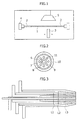
Fig. 1 is a schematic diagram exemplifying an apparatus for producing an optical fiber preform. -
Fig. 2 is a cross-sectional view of a burner for synthesizing glass particulates, having small-diameter gas jet ports. -
Fig. 3 is a schematic longitudinal sectional view exemplifying the burner for synthesizing glass particulates of the invention. -
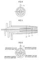
Fig. 4 is a schematic view illustrating the direction of the axial shift for the burner with its axis shifted used in Examples. -
Fig. 5 is a schematic longitudinal sectional view exemplifying a burner for synthesizing glass particulates used in Comparative Examples. -
Fig. 6 is a schematic diagram illustrating the positions at which the linear velocity distribution of the burner is measured. -
Fig. 7 is a graph showing the linear velocity distribution of a fourth tube. -
Fig. 8 is a graph showing the linear velocity distribution of a fifth tube. - As a result of intensive research, as for a multi-nozzle type burner in which multiple gas jet ports are arranged outside small-diameter gas jet ports and are reduced in their diameters at the tips, it was found that individual differences of the burners are highly influenced by the linear velocity distribution at outlets of the gas jet ports arranged outside the small-diameter gas jet ports.
- In other words, when the linear velocity distribution varies greatly at an inert gas jet port arranged outside the small-diameter gas jet ports, inert gas cannot flow sufficiently to the part in which the linear velocity is low, thereby preventing combustible gas and combustion-supporting gas from being sealed completely. Accordingly, the burner tips at the part in which the linear velocity is low are burned to provide the burner susceptible to devitrification.
- Meanwhile, when the linear velocity distribution varies greatly at a jet port for combustible gas or combustion-supporting gas arranged outside the small-diameter gas jet ports, nonuniformity in gas reaction is induced, by which deposition efficiency is decreased and a flame does not come into contact with the deposition surface perpendicularly since the flame is bent. Therefore, a burner with low deposition efficiency is provided.
- The nonuniformity in linear velocity distribution is caused by variations in clearance of a gas flow path due to the axial shift between the tubes of the jet ports. A large amount of gas flows through the part in which clearance is large, whereas gas is not likely to flow through the part in which clearance is small. Much effort, of course, is made by a glass blower to prevent the axial shift, but it is extremely difficult to make the axial shift amount zero.
- Table 1 shows a clearance comparison between cases of large clearance and small clearance, where the inner tubes are the same, and the outer tube axial shift amounts are commonly 0.5 mm. Even with the same axial shift amount, a smaller absolute amount of clearance results in a larger clearance ratio (b/a), whereas a larger absolute amount of clearance results in a smaller clearance ratio (b/a), thereby allowing influence of the axial shift to be reduced relatively. As a result, a smaller absolute amount of clearance leads to great varieties in linear velocity distribution.
(Table 1) Small clearance Large clearance Inner tube diameter mm 30 30 Outer tube diameter mm 32 38 Average clearance mm 1.0 4.0 Minimum clearance (a) mm 0.5 3.5 Maximum clearance (b) mm 1.5 4.5 Clearance ratio (b/a) - 3 1.3 - Accordingly, to reduce individual differences of the burners, i.e. to reduce the variation in linear velocity distribution, it is important not only to avoid setting a predetermined clearance at too small a value when the burner is designed. However, it is more important to prevent clearance from unexpectedly being extremely small at a certain part in a longitudinal direction.
- Here, as for the burner in which multiple gas jet ports are arranged outside small-diameter gas jet ports and are reduced in diameter at the tips, it was found that variations in diameter-reduction start position result in a smaller absolute amount of clearance than the designed clearance at the diameter-reduced part, so that linear velocity distribution tends to vary greatly.
- Since a burner craftsman adjusts the tubes manually, it is extremely difficult to achieve completely the same positions of the diameter-reduced parts and completely the same shapes of the reduced diameters among burners.
- In the part with smaller clearance, the diameter-reduction start position of the outer tube was, in fact, slightly further from the tip than that of the inner tube, although the diameter of each tube is supposed to be reduced at the same position. In such a case, the outer tube was reduced in diameter first to be close to the inner tube, thereby resulting in smaller clearance than the designed clearance.
- In this respect, the present inventors have conducted diligent studies. As a result, the above problem of variation in clearance of a gas flow path, which arises during a process of reducing the diameter of the gas jet port, has been solved in the following manner. Specifically, when the gas jet ports disposed outside the gas jet port enclosing the small-diameter gas jet ports are each reduced in diameter in a direction toward a burner tip, a relationship of L1>L2>L3>... >Ln, where L1, L2, L3, ... Ln represent lengths from the burner tip to diameter-reduction start positions of the outside-disposed gas jet ports in this order from the inside, respectively, so that the more outward the gas jet port is located, the closer to the burner tip the diameter-reduction start position of the gas jet port is.
- Hereinafter, the embodiments of the present invention will be described in detail with reference to the accompanying drawings, but the present invention is not limited thereto.
- In
Fig. 1 , a starting member is welded withdummy rods 2 at both ends of acore rod 1, and rotatably supported by achuck mechanism 4 about an axis. Aburner 3 is configured to laterally move, and is disposed to face the starting member. Optical fiber materials, e.g. vapor of SiCI4 or the like and combustion gas (hydrogen gas and oxygen gas), are sprayed with theburner 3 to the starting member to deposit on the starting member glass particulates (soot) generated by hydrolysis in an oxyhydrogen flame. Then, a deposition layer is formed by reciprocating theburner 3 in the longitudinal direction of the starting member with a burner guide mechanism (not shown), thereby providing a porous glass preform for optical fiber. Now, although not shown, a mechanism may be employed in which the starting member is reciprocated in the longitudinal direction instead of theburner 3. - Thereafter, the porous glass preform for optical fiber is dehydrated in a heating furnace, and then converted to a transparent glass to be a glass preform for optical fiber.
- As shown in
Fig. 2 , aburner 3 for producing a porous glass preform includes a first tube of a glass materialgas jet port 6 in a center, a second tube of a sealgas jet port 7, a third tube of a combustiblegas jet port 8 enclosing eight small-diameter combustion-supportinggas jet ports 11 having a focal length of 150 mm, a fourth tube of a sealgas jet port 9, and a fifth tube of a combustion-supportinggas jet port 10. The tips of thethird tube 8, thefourth tube 9, and thefifth tube 10 are reduced in diameter as shown inFig. 3 . Intentionally, thefourth tube 9 was axially shifted by 0.5 mm relative to thethird tube 8, and thefifth tube 10 was axially shifted by 0.5 mm relative to thefourth tube 9. - As shown in
Fig. 4 , the fourth 9 and the fifth 10 tubes were axially shifted in such a direction that the clearances can be smaller on a side in which thegas inlet 12 tubes of the gas jet ports were disposed. - Prepared were burners that had such a structure in common and had only their diameter-reduction positions varied as shown in Table 2, and then the linear velocity distribution was measured at the burner tips with a hot-wire anemometer at room temperature.
- The
burner 3 used in Examples 1 and 2, as shown inFig. 3 , has a structure in which a tube arranged more outward from the small-diametergas jet ports 11 has a diameter reduced at a position closer to the burner tip (L1>L2>L3). On the other hand, the burner used in Comparative Examples 1 and 2, as shown inFig. 5 , has a structure in which a tube arranged more outward from the small-diametergas jet ports 11 has a diameter reduced at a position more away from the burner tip (L1<L2<L3). - Regarding gases used, the
fourth tube 9 was supplied with N2 as a seal gas at 5 L/min, and thefifth tube 10 was supplied with O2 as a combustion-supporting gas at 40 L/min.(Table 2) Example 1 Example 2 Comparative Example 1 Comparative Example 2 mm mm mm mm Diameter-reduction position of third tube 8L3 70 70 70 70 Diameter-reduction position of fourth tube 9L4 60 65 75 80 diameter-reduction position of fifth tube 10L5 50 60 80 90 - The linear velocity distribution was measured at 90 degree intervals in four directions, i.e. zero o'clock, three o'clock, six o'clock, and nine o'clock directions. Here, as shown in
Fig. 6 , the direction in which thegas inlet 12 tubes of the gas jet ports are disposed is defined as the zero o'clock direction. - As a result, in both of the linear velocity distribution measured at the outlet of the
fourth tube 9 shown inFig. 7 and the linear velocity distribution measured at the outlet of thefifth tube 10 shown inFig. 8 , the linear velocity greatly varied depending on the direction of measurement in the cases of the burners of Comparative Examples, whereas the linear velocity distribution hardly varied in the cases of the burners of Examples in which the more outward the tube was located, the closer to the burner tip the diameter-reduction start position of the tube was. - Next, by using each of the burners in Table 2, and by actually supplying a reaction gas, 100 kg of porous glass particulates were deposited on a starting member having a core rod (outer diameter: 40 mm, length: 2000 mm) and dummy rods (outer diameter: 40 mm) welded at the both ends of the core rod.
- Regarding gases used, the
first tube 6 was supplied with SiCI4 as a glass material gas at 10 L/min and with O2 as a combustion-supporting gas at 20 L/min, thesecond tube 7 was supplied with N2 as a seal gas at 4 L/min, thethird tube 8 was supplied with H2 as a combustible gas at 170 L/min, thefourth tube 9 was supplied with N2 as a seal gas at 5 L/min, thefifth tube 10 was supplied with O2 as a combustion-supporting at 40 L/min, and the small-diametergas jet ports 11 were supplied with O2 as a combustion-supporting gas at 16 L/min. - The result is shown in Table 3.
(Table 3) State of burner tip Deposition efficiency (%) Example 1 No abnormality 68.3 Example 2 No abnormality 68.3 Comparative Example 1 Burned fourth tube tip 67.6 Comparative Example 2 Burned fourth tube tip 65.8 - In Comparative Examples 1 and 2, the tip of the fourth tube in the 0 o'clock direction in which the linear velocity was low was heated red and burned. This was caused by insufficient sealing between a combustible gas in the
third tube 8 and a combustion-supporting gas in thefifth tube 10. In addition, since the combustion-supporting gas was less in thefifth tube 10 in the 0 o'clock direction in which the linear velocity was low, a dark flame was observed at the part. - On the other hand, in Examples 1 and 2, a burned burner tip, an uneven flame, and the like were not observed.
- As a result, Examples exhibited stable and high deposition efficiencies.
-
- 1
- core part
- 2
- dummy rod
- 3
- burner
- 4
- ingot chuck mechanism
- 5
- exhaust hood
- 6
- glass material gas jet port (first tube)
- 7
- seal gas jet port (second tube)
- 8
- combustible gas jet port (third tube)
- 9
- seal gas jet port (fourth tube)
- 10
- combustion-supporting gas jet port (fifth tube)
- 11
- small-diameter combustion-supporting gas jet port
- 12
- gas inlet
- L1
- diameter-reduction start position of third tube
- L2
- diameter-reduction start position of fourth tube
- L3
- diameter-reduction start position of fifth tube (outermost tube)
Claims (2)
- A burner (3) for producing a porous glass preform with a concentric multi-tube structure, comprising:a glass material gas jet port (6) in a center;a plurality of gas jet ports (7, 8, 9, 10) concentrically disposed outside the glass material gas jet port (6); andsmall-diameter gas jet ports (11) which are disposed in a line or a plurality of lines concentrically to the glass material gas jet port (6) so as to be enclosed in one of the gas jet ports other than the gas jet ports (6) in the center and at an outermost side, the small-diameter gas jet ports (11) in the same line having an identical focal length,wherein the gas jet ports disposed outside the gas jet port enclosing the small-diameter gas jet ports (11) are each reduced in diameter in a direction toward a burner tip, and satisfy a relationship of L1>L2>L3>... >Ln, where L1, L2, L3, ... Ln represent lengths from the burner tip to diameter-reduction start positions of the outside-disposed gas jet ports in this order from the inside, respectively, so that the more outward the gas jet port is located, the closer to the burner tip the diameter-reduction start position of the gas jet port is.
- A method for producing a porous glass preform by using the burner (3) for producing a porous glass preform according to the claim 1.
Applications Claiming Priority (1)
| Application Number | Priority Date | Filing Date | Title |
|---|---|---|---|
| JP2010100092A JP5414611B2 (en) | 2010-04-23 | 2010-04-23 | Burner for manufacturing porous glass base material |
Publications (3)
| Publication Number | Publication Date |
|---|---|
| EP2380856A2 true EP2380856A2 (en) | 2011-10-26 |
| EP2380856A3 EP2380856A3 (en) | 2012-05-02 |
| EP2380856B1 EP2380856B1 (en) | 2013-05-29 |
Family
ID=44202513
Family Applications (1)
| Application Number | Title | Priority Date | Filing Date |
|---|---|---|---|
| EP11163597.5A Not-in-force EP2380856B1 (en) | 2010-04-23 | 2011-04-22 | Burner for producing porous glass preform |
Country Status (4)
| Country | Link |
|---|---|
| US (1) | US8459063B2 (en) |
| EP (1) | EP2380856B1 (en) |
| JP (1) | JP5414611B2 (en) |
| CN (1) | CN102234177B (en) |
Families Citing this family (2)
| Publication number | Priority date | Publication date | Assignee | Title |
|---|---|---|---|---|
| JP6826910B2 (en) * | 2017-02-22 | 2021-02-10 | 古河電気工業株式会社 | Multiple tube burner for porous body synthesis and porous body synthesis device |
| JP6623201B2 (en) * | 2017-10-13 | 2019-12-18 | 信越化学工業株式会社 | Burner for synthesis |
Citations (12)
| Publication number | Priority date | Publication date | Assignee | Title |
|---|---|---|---|---|
| JPS62187135A (en) | 1986-02-12 | 1987-08-15 | Furukawa Electric Co Ltd:The | Torch for synthesizing fine glass particle |
| JPH05323130A (en) | 1990-12-27 | 1993-12-07 | Furukawa Electric Co Ltd:The | Multifocal burner and method for manufacturing glass particulate deposit using the burner |
| JP2003165737A (en) | 2001-11-27 | 2003-06-10 | Furukawa Electric Co Ltd:The | Manufacturing method of preform for optical fiber |
| JP2003206154A (en) | 2002-01-15 | 2003-07-22 | Fujikura Ltd | Burner device for producing optical fiber porous preform and method for producing optical fiber porous preform using the same |
| JP2003212555A (en) | 2002-01-16 | 2003-07-30 | Fujikura Ltd | Burner device for producing optical fiber porous preform and method for producing optical fiber porous preform using the same |
| JP2003226544A (en) | 2002-02-01 | 2003-08-12 | Fujikura Ltd | Method for producing porous optical fiber preform |
| JP3543537B2 (en) | 1996-05-09 | 2004-07-14 | 住友電気工業株式会社 | Method for synthesizing glass fine particles and focus burner therefor |
| JP3591330B2 (en) | 1998-10-07 | 2004-11-17 | 住友電気工業株式会社 | Manufacturing method of glass base material |
| JP2004331440A (en) | 2003-05-06 | 2004-11-25 | Sumitomo Electric Ind Ltd | Method for producing porous glass fine particle deposit and burner for glass synthesis used in the production method |
| JP3653902B2 (en) | 1996-12-12 | 2005-06-02 | 住友電気工業株式会社 | Glass base material synthesis burner and glass base material manufacturing method |
| JP3744350B2 (en) | 2000-11-28 | 2006-02-08 | 日立電線株式会社 | Porous glass base material synthesis burner and method for producing porous glass base material |
| JP2006182624A (en) | 2004-12-28 | 2006-07-13 | Fujikura Ltd | Method for producing glass rod |
Family Cites Families (6)
| Publication number | Priority date | Publication date | Assignee | Title |
|---|---|---|---|---|
| JP3520541B2 (en) * | 1993-12-27 | 2004-04-19 | 株式会社ニコン | Quartz glass burner, quartz glass produced using the same, method for producing quartz glass using quartz glass burner |
| US7143610B2 (en) * | 2001-03-23 | 2006-12-05 | Vitro Global, S.A. | Method and system for feeding and burning a pulverized fuel in a glass melting furnace, and burner for use in the same |
| JP4220809B2 (en) * | 2003-03-11 | 2009-02-04 | 株式会社フジクラ | Burner for synthesizing glass fine particles and method for producing porous preform for optical fiber |
| JP2007076957A (en) * | 2005-09-14 | 2007-03-29 | Sumitomo Electric Ind Ltd | Glass synthesis burner and method for producing glass particulate deposit using the burner |
| JP5236526B2 (en) * | 2008-02-27 | 2013-07-17 | 信越化学工業株式会社 | Burner for manufacturing porous glass base material |
| JP5264543B2 (en) * | 2008-02-27 | 2013-08-14 | 信越化学工業株式会社 | Manufacturing method of optical fiber preform |
-
2010
- 2010-04-23 JP JP2010100092A patent/JP5414611B2/en not_active Expired - Fee Related
-
2011
- 2011-04-20 CN CN201110100265.5A patent/CN102234177B/en not_active Expired - Fee Related
- 2011-04-22 US US13/092,311 patent/US8459063B2/en not_active Expired - Fee Related
- 2011-04-22 EP EP11163597.5A patent/EP2380856B1/en not_active Not-in-force
Patent Citations (12)
| Publication number | Priority date | Publication date | Assignee | Title |
|---|---|---|---|---|
| JPS62187135A (en) | 1986-02-12 | 1987-08-15 | Furukawa Electric Co Ltd:The | Torch for synthesizing fine glass particle |
| JPH05323130A (en) | 1990-12-27 | 1993-12-07 | Furukawa Electric Co Ltd:The | Multifocal burner and method for manufacturing glass particulate deposit using the burner |
| JP3543537B2 (en) | 1996-05-09 | 2004-07-14 | 住友電気工業株式会社 | Method for synthesizing glass fine particles and focus burner therefor |
| JP3653902B2 (en) | 1996-12-12 | 2005-06-02 | 住友電気工業株式会社 | Glass base material synthesis burner and glass base material manufacturing method |
| JP3591330B2 (en) | 1998-10-07 | 2004-11-17 | 住友電気工業株式会社 | Manufacturing method of glass base material |
| JP3744350B2 (en) | 2000-11-28 | 2006-02-08 | 日立電線株式会社 | Porous glass base material synthesis burner and method for producing porous glass base material |
| JP2003165737A (en) | 2001-11-27 | 2003-06-10 | Furukawa Electric Co Ltd:The | Manufacturing method of preform for optical fiber |
| JP2003206154A (en) | 2002-01-15 | 2003-07-22 | Fujikura Ltd | Burner device for producing optical fiber porous preform and method for producing optical fiber porous preform using the same |
| JP2003212555A (en) | 2002-01-16 | 2003-07-30 | Fujikura Ltd | Burner device for producing optical fiber porous preform and method for producing optical fiber porous preform using the same |
| JP2003226544A (en) | 2002-02-01 | 2003-08-12 | Fujikura Ltd | Method for producing porous optical fiber preform |
| JP2004331440A (en) | 2003-05-06 | 2004-11-25 | Sumitomo Electric Ind Ltd | Method for producing porous glass fine particle deposit and burner for glass synthesis used in the production method |
| JP2006182624A (en) | 2004-12-28 | 2006-07-13 | Fujikura Ltd | Method for producing glass rod |
Also Published As
| Publication number | Publication date |
|---|---|
| US8459063B2 (en) | 2013-06-11 |
| CN102234177A (en) | 2011-11-09 |
| EP2380856B1 (en) | 2013-05-29 |
| JP2011230935A (en) | 2011-11-17 |
| CN102234177B (en) | 2015-03-25 |
| US20110259055A1 (en) | 2011-10-27 |
| JP5414611B2 (en) | 2014-02-12 |
| EP2380856A3 (en) | 2012-05-02 |
Similar Documents
| Publication | Publication Date | Title |
|---|---|---|
| EP2583952B1 (en) | Method and burner for producing a porous glass preform | |
| CN101965316B (en) | Burner for manufacturing porous glass base material | |
| CN108017271B (en) | OVD strip blowtorch device and OVD rod making system and their use methods | |
| US9260339B2 (en) | Method of fabricating an optical fiber preform and a burner therefor | |
| EP2380855B1 (en) | Burner for manufacturing porous glass preform | |
| EP2096087B1 (en) | Burner for fabricating optical fiber preform | |
| EP2380856B1 (en) | Burner for producing porous glass preform | |
| CN1807302B (en) | Method for manufacturing glass rod | |
| US20140083140A1 (en) | Method of manufacturing porous glass deposition body for optical fiber | |
| EP2221281B1 (en) | Burner for manufacturing porous glass base material, and manufacturing method of porous glass base material | |
| EP2098488B9 (en) | Method of fabricating optical fiber preform | |
| CN109626809B (en) | Method for preparing porous glass deposit for optical fiber | |
| EP2573054B1 (en) | Method for manufacturing an optical fiber preform by flame hydrolysis | |
| KR101036064B1 (en) | Burner for manufacturing porous glass base material | |
| EP2223899B1 (en) | Burner for producing glass fine particles and method for manufacturing porous glass base material using the same | |
| JP6066103B2 (en) | Burner for manufacturing porous glass base material | |
| US20060185399A1 (en) | Apparatus for fabricating optical fiber preform through external vapor deposition process | |
| CN1824620A (en) | Apparatus for fabricating optical fiber preform through external vapor deposition process | |
| JPH0457621B2 (en) |
Legal Events
| Date | Code | Title | Description |
|---|---|---|---|
| AK | Designated contracting states |
Kind code of ref document: A2 Designated state(s): AL AT BE BG CH CY CZ DE DK EE ES FI FR GB GR HR HU IE IS IT LI LT LU LV MC MK MT NL NO PL PT RO RS SE SI SK SM TR |
|
| AX | Request for extension of the european patent |
Extension state: BA ME |
|
| PUAI | Public reference made under article 153(3) epc to a published international application that has entered the european phase |
Free format text: ORIGINAL CODE: 0009012 |
|
| PUAL | Search report despatched |
Free format text: ORIGINAL CODE: 0009013 |
|
| AK | Designated contracting states |
Kind code of ref document: A3 Designated state(s): AL AT BE BG CH CY CZ DE DK EE ES FI FR GB GR HR HU IE IS IT LI LT LU LV MC MK MT NL NO PL PT RO RS SE SI SK SM TR |
|
| AX | Request for extension of the european patent |
Extension state: BA ME |
|
| RIC1 | Information provided on ipc code assigned before grant |
Ipc: C03B 37/014 20060101AFI20120327BHEP |
|
| GRAP | Despatch of communication of intention to grant a patent |
Free format text: ORIGINAL CODE: EPIDOSNIGR1 |
|
| 17P | Request for examination filed |
Effective date: 20120920 |
|
| GRAC | Information related to communication of intention to grant a patent modified |
Free format text: ORIGINAL CODE: EPIDOSCIGR1 |
|
| RIN1 | Information on inventor provided before grant (corrected) |
Inventor name: YOSHIDA, MAKOTO |
|
| GRAS | Grant fee paid |
Free format text: ORIGINAL CODE: EPIDOSNIGR3 |
|
| GRAA | (expected) grant |
Free format text: ORIGINAL CODE: 0009210 |
|
| AK | Designated contracting states |
Kind code of ref document: B1 Designated state(s): AL AT BE BG CH CY CZ DE DK EE ES FI FR GB GR HR HU IE IS IT LI LT LU LV MC MK MT NL NO PL PT RO RS SE SI SK SM TR |
|
| REG | Reference to a national code |
Ref country code: GB Ref legal event code: FG4D |
|
| REG | Reference to a national code |
Ref country code: CH Ref legal event code: EP |
|
| REG | Reference to a national code |
Ref country code: AT Ref legal event code: REF Ref document number: 614301 Country of ref document: AT Kind code of ref document: T Effective date: 20130615 |
|
| REG | Reference to a national code |
Ref country code: IE Ref legal event code: FG4D |
|
| REG | Reference to a national code |
Ref country code: DE Ref legal event code: R096 Ref document number: 602011001782 Country of ref document: DE Effective date: 20130725 |
|
| REG | Reference to a national code |
Ref country code: AT Ref legal event code: MK05 Ref document number: 614301 Country of ref document: AT Kind code of ref document: T Effective date: 20130529 |
|
| REG | Reference to a national code |
Ref country code: LT Ref legal event code: MG4D |
|
| PG25 | Lapsed in a contracting state [announced via postgrant information from national office to epo] |
Ref country code: GR Free format text: LAPSE BECAUSE OF FAILURE TO SUBMIT A TRANSLATION OF THE DESCRIPTION OR TO PAY THE FEE WITHIN THE PRESCRIBED TIME-LIMIT Effective date: 20130830 Ref country code: LT Free format text: LAPSE BECAUSE OF FAILURE TO SUBMIT A TRANSLATION OF THE DESCRIPTION OR TO PAY THE FEE WITHIN THE PRESCRIBED TIME-LIMIT Effective date: 20130529 Ref country code: SE Free format text: LAPSE BECAUSE OF FAILURE TO SUBMIT A TRANSLATION OF THE DESCRIPTION OR TO PAY THE FEE WITHIN THE PRESCRIBED TIME-LIMIT Effective date: 20130529 Ref country code: IS Free format text: LAPSE BECAUSE OF FAILURE TO SUBMIT A TRANSLATION OF THE DESCRIPTION OR TO PAY THE FEE WITHIN THE PRESCRIBED TIME-LIMIT Effective date: 20130929 Ref country code: NO Free format text: LAPSE BECAUSE OF FAILURE TO SUBMIT A TRANSLATION OF THE DESCRIPTION OR TO PAY THE FEE WITHIN THE PRESCRIBED TIME-LIMIT Effective date: 20130829 Ref country code: ES Free format text: LAPSE BECAUSE OF FAILURE TO SUBMIT A TRANSLATION OF THE DESCRIPTION OR TO PAY THE FEE WITHIN THE PRESCRIBED TIME-LIMIT Effective date: 20130909 Ref country code: AT Free format text: LAPSE BECAUSE OF FAILURE TO SUBMIT A TRANSLATION OF THE DESCRIPTION OR TO PAY THE FEE WITHIN THE PRESCRIBED TIME-LIMIT Effective date: 20130529 Ref country code: PT Free format text: LAPSE BECAUSE OF FAILURE TO SUBMIT A TRANSLATION OF THE DESCRIPTION OR TO PAY THE FEE WITHIN THE PRESCRIBED TIME-LIMIT Effective date: 20130930 Ref country code: FI Free format text: LAPSE BECAUSE OF FAILURE TO SUBMIT A TRANSLATION OF THE DESCRIPTION OR TO PAY THE FEE WITHIN THE PRESCRIBED TIME-LIMIT Effective date: 20130529 Ref country code: SI Free format text: LAPSE BECAUSE OF FAILURE TO SUBMIT A TRANSLATION OF THE DESCRIPTION OR TO PAY THE FEE WITHIN THE PRESCRIBED TIME-LIMIT Effective date: 20130529 |
|
| REG | Reference to a national code |
Ref country code: NL Ref legal event code: VDEP Effective date: 20130529 |
|
| PG25 | Lapsed in a contracting state [announced via postgrant information from national office to epo] |
Ref country code: RS Free format text: LAPSE BECAUSE OF FAILURE TO SUBMIT A TRANSLATION OF THE DESCRIPTION OR TO PAY THE FEE WITHIN THE PRESCRIBED TIME-LIMIT Effective date: 20130529 Ref country code: HR Free format text: LAPSE BECAUSE OF FAILURE TO SUBMIT A TRANSLATION OF THE DESCRIPTION OR TO PAY THE FEE WITHIN THE PRESCRIBED TIME-LIMIT Effective date: 20130529 Ref country code: BG Free format text: LAPSE BECAUSE OF FAILURE TO SUBMIT A TRANSLATION OF THE DESCRIPTION OR TO PAY THE FEE WITHIN THE PRESCRIBED TIME-LIMIT Effective date: 20130829 Ref country code: PL Free format text: LAPSE BECAUSE OF FAILURE TO SUBMIT A TRANSLATION OF THE DESCRIPTION OR TO PAY THE FEE WITHIN THE PRESCRIBED TIME-LIMIT Effective date: 20130529 |
|
| PG25 | Lapsed in a contracting state [announced via postgrant information from national office to epo] |
Ref country code: LV Free format text: LAPSE BECAUSE OF FAILURE TO SUBMIT A TRANSLATION OF THE DESCRIPTION OR TO PAY THE FEE WITHIN THE PRESCRIBED TIME-LIMIT Effective date: 20130529 |
|
| PG25 | Lapsed in a contracting state [announced via postgrant information from national office to epo] |
Ref country code: EE Free format text: LAPSE BECAUSE OF FAILURE TO SUBMIT A TRANSLATION OF THE DESCRIPTION OR TO PAY THE FEE WITHIN THE PRESCRIBED TIME-LIMIT Effective date: 20130529 Ref country code: SK Free format text: LAPSE BECAUSE OF FAILURE TO SUBMIT A TRANSLATION OF THE DESCRIPTION OR TO PAY THE FEE WITHIN THE PRESCRIBED TIME-LIMIT Effective date: 20130529 Ref country code: DK Free format text: LAPSE BECAUSE OF FAILURE TO SUBMIT A TRANSLATION OF THE DESCRIPTION OR TO PAY THE FEE WITHIN THE PRESCRIBED TIME-LIMIT Effective date: 20130529 Ref country code: CZ Free format text: LAPSE BECAUSE OF FAILURE TO SUBMIT A TRANSLATION OF THE DESCRIPTION OR TO PAY THE FEE WITHIN THE PRESCRIBED TIME-LIMIT Effective date: 20130529 Ref country code: BE Free format text: LAPSE BECAUSE OF FAILURE TO SUBMIT A TRANSLATION OF THE DESCRIPTION OR TO PAY THE FEE WITHIN THE PRESCRIBED TIME-LIMIT Effective date: 20130529 |
|
| PG25 | Lapsed in a contracting state [announced via postgrant information from national office to epo] |
Ref country code: IT Free format text: LAPSE BECAUSE OF FAILURE TO SUBMIT A TRANSLATION OF THE DESCRIPTION OR TO PAY THE FEE WITHIN THE PRESCRIBED TIME-LIMIT Effective date: 20130529 Ref country code: RO Free format text: LAPSE BECAUSE OF FAILURE TO SUBMIT A TRANSLATION OF THE DESCRIPTION OR TO PAY THE FEE WITHIN THE PRESCRIBED TIME-LIMIT Effective date: 20130529 Ref country code: NL Free format text: LAPSE BECAUSE OF FAILURE TO SUBMIT A TRANSLATION OF THE DESCRIPTION OR TO PAY THE FEE WITHIN THE PRESCRIBED TIME-LIMIT Effective date: 20130529 |
|
| PLBE | No opposition filed within time limit |
Free format text: ORIGINAL CODE: 0009261 |
|
| STAA | Information on the status of an ep patent application or granted ep patent |
Free format text: STATUS: NO OPPOSITION FILED WITHIN TIME LIMIT |
|
| 26N | No opposition filed |
Effective date: 20140303 |
|
| REG | Reference to a national code |
Ref country code: DE Ref legal event code: R097 Ref document number: 602011001782 Country of ref document: DE Effective date: 20140303 |
|
| PG25 | Lapsed in a contracting state [announced via postgrant information from national office to epo] |
Ref country code: LU Free format text: LAPSE BECAUSE OF FAILURE TO SUBMIT A TRANSLATION OF THE DESCRIPTION OR TO PAY THE FEE WITHIN THE PRESCRIBED TIME-LIMIT Effective date: 20140422 Ref country code: MC Free format text: LAPSE BECAUSE OF FAILURE TO SUBMIT A TRANSLATION OF THE DESCRIPTION OR TO PAY THE FEE WITHIN THE PRESCRIBED TIME-LIMIT Effective date: 20130529 |
|
| REG | Reference to a national code |
Ref country code: CH Ref legal event code: PL |
|
| REG | Reference to a national code |
Ref country code: IE Ref legal event code: MM4A |
|
| PG25 | Lapsed in a contracting state [announced via postgrant information from national office to epo] |
Ref country code: CH Free format text: LAPSE BECAUSE OF NON-PAYMENT OF DUE FEES Effective date: 20140430 Ref country code: LI Free format text: LAPSE BECAUSE OF NON-PAYMENT OF DUE FEES Effective date: 20140430 |
|
| PG25 | Lapsed in a contracting state [announced via postgrant information from national office to epo] |
Ref country code: IE Free format text: LAPSE BECAUSE OF NON-PAYMENT OF DUE FEES Effective date: 20140422 |
|
| GBPC | Gb: european patent ceased through non-payment of renewal fee |
Effective date: 20150422 |
|
| PG25 | Lapsed in a contracting state [announced via postgrant information from national office to epo] |
Ref country code: GB Free format text: LAPSE BECAUSE OF NON-PAYMENT OF DUE FEES Effective date: 20150422 |
|
| REG | Reference to a national code |
Ref country code: FR Ref legal event code: PLFP Year of fee payment: 6 |
|
| PG25 | Lapsed in a contracting state [announced via postgrant information from national office to epo] |
Ref country code: MT Free format text: LAPSE BECAUSE OF FAILURE TO SUBMIT A TRANSLATION OF THE DESCRIPTION OR TO PAY THE FEE WITHIN THE PRESCRIBED TIME-LIMIT Effective date: 20130529 |
|
| PG25 | Lapsed in a contracting state [announced via postgrant information from national office to epo] |
Ref country code: SM Free format text: LAPSE BECAUSE OF FAILURE TO SUBMIT A TRANSLATION OF THE DESCRIPTION OR TO PAY THE FEE WITHIN THE PRESCRIBED TIME-LIMIT Effective date: 20130529 |
|
| PG25 | Lapsed in a contracting state [announced via postgrant information from national office to epo] |
Ref country code: CY Free format text: LAPSE BECAUSE OF FAILURE TO SUBMIT A TRANSLATION OF THE DESCRIPTION OR TO PAY THE FEE WITHIN THE PRESCRIBED TIME-LIMIT Effective date: 20130529 |
|
| PG25 | Lapsed in a contracting state [announced via postgrant information from national office to epo] |
Ref country code: HU Free format text: LAPSE BECAUSE OF FAILURE TO SUBMIT A TRANSLATION OF THE DESCRIPTION OR TO PAY THE FEE WITHIN THE PRESCRIBED TIME-LIMIT; INVALID AB INITIO Effective date: 20110422 Ref country code: TR Free format text: LAPSE BECAUSE OF FAILURE TO SUBMIT A TRANSLATION OF THE DESCRIPTION OR TO PAY THE FEE WITHIN THE PRESCRIBED TIME-LIMIT Effective date: 20130529 |
|
| REG | Reference to a national code |
Ref country code: FR Ref legal event code: PLFP Year of fee payment: 7 |
|
| REG | Reference to a national code |
Ref country code: FR Ref legal event code: PLFP Year of fee payment: 8 |
|
| PG25 | Lapsed in a contracting state [announced via postgrant information from national office to epo] |
Ref country code: MK Free format text: LAPSE BECAUSE OF FAILURE TO SUBMIT A TRANSLATION OF THE DESCRIPTION OR TO PAY THE FEE WITHIN THE PRESCRIBED TIME-LIMIT Effective date: 20130529 |
|
| PG25 | Lapsed in a contracting state [announced via postgrant information from national office to epo] |
Ref country code: AL Free format text: LAPSE BECAUSE OF FAILURE TO SUBMIT A TRANSLATION OF THE DESCRIPTION OR TO PAY THE FEE WITHIN THE PRESCRIBED TIME-LIMIT Effective date: 20130529 |
|
| PGFP | Annual fee paid to national office [announced via postgrant information from national office to epo] |
Ref country code: FR Payment date: 20230309 Year of fee payment: 13 |
|
| PGFP | Annual fee paid to national office [announced via postgrant information from national office to epo] |
Ref country code: DE Payment date: 20230228 Year of fee payment: 13 |
|
| REG | Reference to a national code |
Ref country code: DE Ref legal event code: R119 Ref document number: 602011001782 Country of ref document: DE |
|
| PG25 | Lapsed in a contracting state [announced via postgrant information from national office to epo] |
Ref country code: DE Free format text: LAPSE BECAUSE OF NON-PAYMENT OF DUE FEES Effective date: 20241105 |
|
| PG25 | Lapsed in a contracting state [announced via postgrant information from national office to epo] |
Ref country code: FR Free format text: LAPSE BECAUSE OF NON-PAYMENT OF DUE FEES Effective date: 20240430 |
|
| PG25 | Lapsed in a contracting state [announced via postgrant information from national office to epo] |
Ref country code: FR Free format text: LAPSE BECAUSE OF NON-PAYMENT OF DUE FEES Effective date: 20240430 Ref country code: DE Free format text: LAPSE BECAUSE OF NON-PAYMENT OF DUE FEES Effective date: 20241105 |