EP2380810A2 - Machine for packaging, by sealing with synthetic film, products, particularly food products, in containers such as trays, tubs or the like, with high flexibility in use - Google Patents
Machine for packaging, by sealing with synthetic film, products, particularly food products, in containers such as trays, tubs or the like, with high flexibility in use Download PDFInfo
- Publication number
- EP2380810A2 EP2380810A2 EP11157792A EP11157792A EP2380810A2 EP 2380810 A2 EP2380810 A2 EP 2380810A2 EP 11157792 A EP11157792 A EP 11157792A EP 11157792 A EP11157792 A EP 11157792A EP 2380810 A2 EP2380810 A2 EP 2380810A2
- Authority
- EP
- European Patent Office
- Prior art keywords
- packaging
- containers
- station
- sealing film
- bell
- Prior art date
- Legal status (The legal status is an assumption and is not a legal conclusion. Google has not performed a legal analysis and makes no representation as to the accuracy of the status listed.)
- Withdrawn
Links
Images


Classifications
-
- B—PERFORMING OPERATIONS; TRANSPORTING
- B65—CONVEYING; PACKING; STORING; HANDLING THIN OR FILAMENTARY MATERIAL
- B65B—MACHINES, APPARATUS OR DEVICES FOR, OR METHODS OF, PACKAGING ARTICLES OR MATERIALS; UNPACKING
- B65B31/00—Packaging articles or materials under special atmospheric or gaseous conditions; Adding propellants to aerosol containers
- B65B31/02—Filling, closing, or filling and closing, containers or wrappers in chambers maintained under vacuum or superatmospheric pressure or containing a special atmosphere, e.g. of inert gas
- B65B31/025—Filling, closing, or filling and closing, containers or wrappers in chambers maintained under vacuum or superatmospheric pressure or containing a special atmosphere, e.g. of inert gas specially adapted for rigid or semi-rigid containers
- B65B31/028—Filling, closing, or filling and closing, containers or wrappers in chambers maintained under vacuum or superatmospheric pressure or containing a special atmosphere, e.g. of inert gas specially adapted for rigid or semi-rigid containers closed by a lid sealed to the upper rim of the container, e.g. tray-like container
-
- B—PERFORMING OPERATIONS; TRANSPORTING
- B65—CONVEYING; PACKING; STORING; HANDLING THIN OR FILAMENTARY MATERIAL
- B65B—MACHINES, APPARATUS OR DEVICES FOR, OR METHODS OF, PACKAGING ARTICLES OR MATERIALS; UNPACKING
- B65B59/00—Arrangements to enable machines to handle articles of different sizes, to produce packages of different sizes, to vary the contents of packages, to handle different types of packaging material, or to give access for cleaning or maintenance purposes
- B65B59/003—Arrangements to enable adjustments related to the packaging material
-
- B—PERFORMING OPERATIONS; TRANSPORTING
- B65—CONVEYING; PACKING; STORING; HANDLING THIN OR FILAMENTARY MATERIAL
- B65B—MACHINES, APPARATUS OR DEVICES FOR, OR METHODS OF, PACKAGING ARTICLES OR MATERIALS; UNPACKING
- B65B59/00—Arrangements to enable machines to handle articles of different sizes, to produce packages of different sizes, to vary the contents of packages, to handle different types of packaging material, or to give access for cleaning or maintenance purposes
- B65B59/02—Arrangements to enable adjustments to be made while the machine is running
-
- B—PERFORMING OPERATIONS; TRANSPORTING
- B65—CONVEYING; PACKING; STORING; HANDLING THIN OR FILAMENTARY MATERIAL
- B65B—MACHINES, APPARATUS OR DEVICES FOR, OR METHODS OF, PACKAGING ARTICLES OR MATERIALS; UNPACKING
- B65B7/00—Closing containers or receptacles after filling
- B65B7/16—Closing semi-rigid or rigid containers or receptacles not deformed by, or not taking-up shape of, contents, e.g. boxes or cartons
- B65B7/168—Closing semi-rigid or rigid containers or receptacles not deformed by, or not taking-up shape of, contents, e.g. boxes or cartons by applying and securing double closures
-
- B—PERFORMING OPERATIONS; TRANSPORTING
- B65—CONVEYING; PACKING; STORING; HANDLING THIN OR FILAMENTARY MATERIAL
- B65B—MACHINES, APPARATUS OR DEVICES FOR, OR METHODS OF, PACKAGING ARTICLES OR MATERIALS; UNPACKING
- B65B2210/00—Specific aspects of the packaging machine
- B65B2210/02—Plurality of alternative input or output lines or plurality of alternative packaging units on the same packaging line for improving machine flexibility
-
- B—PERFORMING OPERATIONS; TRANSPORTING
- B65—CONVEYING; PACKING; STORING; HANDLING THIN OR FILAMENTARY MATERIAL
- B65B—MACHINES, APPARATUS OR DEVICES FOR, OR METHODS OF, PACKAGING ARTICLES OR MATERIALS; UNPACKING
- B65B51/00—Devices for, or methods of, sealing or securing package folds or closures; Devices for gathering or twisting wrappers, or necks of bags
- B65B51/10—Applying or generating heat or pressure or combinations thereof
- B65B51/14—Applying or generating heat or pressure or combinations thereof by reciprocating or oscillating members
-
- B—PERFORMING OPERATIONS; TRANSPORTING
- B65—CONVEYING; PACKING; STORING; HANDLING THIN OR FILAMENTARY MATERIAL
- B65B—MACHINES, APPARATUS OR DEVICES FOR, OR METHODS OF, PACKAGING ARTICLES OR MATERIALS; UNPACKING
- B65B59/00—Arrangements to enable machines to handle articles of different sizes, to produce packages of different sizes, to vary the contents of packages, to handle different types of packaging material, or to give access for cleaning or maintenance purposes
- B65B59/005—Adjustable conveying means
-
- B—PERFORMING OPERATIONS; TRANSPORTING
- B65—CONVEYING; PACKING; STORING; HANDLING THIN OR FILAMENTARY MATERIAL
- B65B—MACHINES, APPARATUS OR DEVICES FOR, OR METHODS OF, PACKAGING ARTICLES OR MATERIALS; UNPACKING
- B65B7/00—Closing containers or receptacles after filling
- B65B7/16—Closing semi-rigid or rigid containers or receptacles not deformed by, or not taking-up shape of, contents, e.g. boxes or cartons
- B65B7/162—Closing semi-rigid or rigid containers or receptacles not deformed by, or not taking-up shape of, contents, e.g. boxes or cartons by feeding web material to securing means
- B65B7/164—Securing by heat-sealing
Definitions
- the present invention relates to a machine for packaging, by sealing with synthetic film, products, particularly food products, in containers such as trays, tubs or the like.
- Machines are known for packaging products, particularly food products, in preformed containers, such as trays, tubs or the like, by means of the application, performed usually by heat-sealing or similar methods, of a synthetic film arranged to close the mouth of the containers.
- Such conventional machines generally comprise a resting contact surface that extends from a station for loading the containers to a packaging station and along which the containers are pushed by way of adapted moving means within lateral guides that delimit laterally the advancement path of the containers.
- a packaging chamber is generally provided that is composed of a lower bell, which is open upwardly, and an upper bell, which is open downwardly and faces the lower chamber.
- the lower bell there is at least one supporting pan for at least one container and a lower mold part that can engage the protruding rim that delimits the mouth of the container or containers to be sealed
- an upper mold part provided with means for sealing the synthetic film that is arranged between the lower bell and the upper bell.
- the lower bell can be lifted in order to lift the container toward the upper mold part and to engage the upper bell, delimiting a compartment that is hermetically sealed toward the outside and, according to the type of packaging to be performed, can be connected simply to a vacuum pump (vacuum packaging) or, sequentially, to a vacuum pump and to a line for supplying a gas or a gas mixture (modified atmosphere packaging).
- a vacuum pump vacuum packaging
- a gas or a gas mixture modified atmosphere packaging
- the sealing film unwinds from a supply spool to a waste winding roll by passing, in the packaging station, between the lower bell and the upper bell.
- the upper mold part can move vertically with respect to the upper bell in order to engage the lower mold part and perform sealing, generally heat-sealing, of the film that passes between the two mold parts.
- the upper mold part in closing onto the lower mold part, seals the film on the rim that delimits the mouth of the container or containers carried by the lower mold part and cuts the film along the rim of the container or containers.
- Such machines are capable of performing the packaging of a container or a group of containers, as many as can be accommodated inside the packaging chamber.
- Machines for large production runs are also known in which two packaging chambers are provided in the packaging station.
- a same sealing film is used for both packaging chambers and unwinds, similarly to machines with a single packaging chamber, from a supply spool to a waste winding roll, and the two packaging chambers are used simultaneously, obtaining the advantage of doubling the productivity of the machine in comparison to machines with a single packaging chamber.
- Machines of the known type are not devoid of problems and drawbacks.
- the aim of the present invention is to solve the problems and overcome the drawbacks described above, by providing a machine that can adapt in an extremely simple and quick way to the several requirements of use.
- an object of the invention is to provide a machine that can pass quickly from the packaging of containers of one format to the packaging of containers of a different format.
- Another object of the invention is to provide a machine that can increase its productivity when required.
- a further object of the invention is to provide a machine that can perform, in a single pass, two distinct packaging steps, as required for example in packaging with a seal of the "skin" type followed by a traditional seal.
- Another object of the invention is to provide a machine that is highly reliable and precise in operation.
- a machine for packaging by sealing with synthetic film, products, particularly food products, in containers such as trays, tubs or the like, comprising means for moving the containers, in which the products to be packaged are arranged, along an advancement direction from a station for loading the containers to a station for unloading the containers, between said loading station and said unloading station there being a packaging station provided with means for positioning a sealing film on the upper side to be sealed of the containers and with means for heat-sealing said sealing film on the containers, characterized in that, in said packaging station, at least two packaging chambers are provided, each of said packaging chambers being served by corresponding means for positioning a sealing film, which can be used autonomously with respect to those that serve another packaging chamber located in said packaging station.
- the machine according to the invention comprises, in a per se known manner, a supporting structure 2, which is provided with feet for resting on the ground and supports means 3 for moving the containers 60, in which the products to be packaged are arranged, along an advancement direction 4 from a loading station 5 to an unloading station 6 for the containers 60.
- a packaging station 7 which is provided with means 8, 9 for positioning a sealing film 10, 11 on the upper side to be sealed of the containers 60 and with means 12, 13 for sealing the sealing film 10, 11 on the containers 60.
- each one of the packaging chambers 14 or 15 is served by corresponding means 8, 9 for positioning a sealing film 10, 11, which can be used autonomously with respect to those that serve another packaging chamber 15 or 14 located in the packaging station 7.
- each packaging chamber 14, 15 comprises a lower bell 16, 17, which is open upwardly and accommodates at least one supporting pan 18, 19, which defines a substantially horizontal resting contact surface for a corresponding container, and a lower mold part 20, 21, which is provided in a per se known manner and can engage the rim that surrounds the mouth of the containers 60 and protrudes outwardly.
- the lower mold part 20, 21 is substantially constituted by a frame, which is shaped so as to correspond to the shape of the container or containers 60 which it must engage.
- the supporting pans 18, 19, which are arranged inside the lower bell 16, 17 and are designed to support a container or a group of containers 60, correspond to the region or regions delimited by the frame that constitutes the lower mold part 20, 21 and is connected to the upper rim of the corresponding lower bell 16, 17.
- Each packaging chamber 14, 15 also comprises an upper bell 22, 23, which is open downwardly and faces upwardly the lower bell 16, 17, which accommodates an upper mold part 24, 25, which faces the lower mold part 20, 21 and is provided with means, of the known type and not shown in the figures, for sealing the corresponding sealing film 10, 11 on the rim that delimits the mouth of the container or containers 60 arranged at the corresponding packaging chamber 14, 15. More particularly, such sealing means can be constituted, in a per se known manner, by electric resistance heaters which are applied to the upper mold part 24, 25 and can be activated to heat the upper mold part 24, 25 to a temperature suitable to seal the corresponding sealing film 10, 11 on the rim of the container or containers 60.
- the upper mold part 24, 25 is provided, moreover, in a per se known manner, with blades for cutting the sealing film 10, 11 around the rim of the container or containers 60.
- lifting means 26, 27 for lifting the lower bell 16, 17 and the lower mold part 20, 21 toward the upper bell 22, 23 of each packaging chamber 14, 15.
- the lifting means 26, 27 comprise, for each lower bell 16, 17, a fluid-operated cylinder 28, 29, with a vertical axis, which is connected by means of its body to the supporting structure 2 and by means of the upper end of the stem of its piston to the lower side of the corresponding lower bell 16, 17.
- Each upper mold part 24, 25 is connected to the lower end of the stem of the piston of a corresponding fluid-operated cylinder 30, 31, having vertical axis, which is connected by means of its body to the corresponding upper bell 22, 23.
- the fluid-operated cylinder 30, 31 can be actuated to lower the corresponding upper mold part 24, 25 toward the lower mold part 20, 21 or to lift it, as will become better apparent hereinafter.
- each packaging chamber 14, 15 there are, in a per se known manner, sensors 32, 33 for detecting the arrival, inside each packaging chamber 14, 15, on the supporting pans 18, 19, of a container or a group of containers 60.
- the sensors 32, 33 are arranged outside the volume of the upper bell 22, 23 and of the lower bell 16, 17 so as not to hinder the operations for opening and closing the packaging chambers 14, 15 following the lifting and lowering of the lower bells 16, 17 with respect to the upper bells 22, 23.
- the corresponding lower bell 16, 17 and the corresponding upper bell 22, 23, once closed against each other delimit a compartment that is adapted to contain a container or a group of containers 60 and can be connected, in a per se known manner, to a vacuum pump and/or to a line for supplying a gas or a gas mixture, depending on whether vacuum packaging or modified atmosphere packaging is required.
- the means 8, 9 for positioning a sealing film 10, 11 comprise, for each one of the packaging chambers 14, 15, a spool 34, 35 for supplying the sealing film 10, 11, a roll for winding the waste 36, 37 of the sealing film 10, 11, and guiding rollers 38, 39, which define, for the sealing film 10, 11, a path that runs from the supply spool 34, 35 to the waste winding roll 36, 37.
- the path of the sealing film 10, 11 runs partly between the lower bell 16, 17 and the upper bell 22, 23 of the corresponding packaging chamber 14, 15.
- the waste winding roll 36, 37 is actuated by a gearmotor 40, 41 and the unwinding of the sealing film 10, 11 from the supply spool 34, 35 is assisted by a motorized roller 42, 43, optionally connected to the same gearmotor 40, 41 or actuated by an autonomous gearmotor 44, against which a presser roller 45, 46 acts.
- each sealing film 10, 11 from the supply spool 34, 35 to the corresponding packaging chamber 14, 15 there can be, in a per se known manner, a unit 47, 48 for centering the print that is optionally present on the sealing film 10, 11.
- FIG. 2 and 3 which refers to a machine for performing packaging with a seal of the "skin" type followed by a traditional seal, between the supply spool 34 and the first packaging chamber 14, i.e. the packaging chamber that is encountered first by the containers 60 in their advancement path from the loading station 5 to the unloading station 6, a plate 49 for heating the sealing film 10, 11 is provided.
- the means 3 for moving the containers 60 comprise a pair of chains 50 which are arranged side-by-side and laterally, on mutually opposite sides, with respect to a vertical central plane that is parallel to the advancement direction 4 and traction elements 51 which are arranged at right angles to the advancement direction 4 and are fixed to the chains 50.
- a substantially horizontal resting contact surface 52 which is fixed to the supporting structure 2.
- lateral guides not visible in the figures, that delimit laterally the advancement path of the containers 60. The distance of such lateral guides can be changed, in a per se known manner, in order to adapt it to the dimensions of the containers 60.
- the chains 50 engage corresponding pinions 53, which are supported so as to rotate about their own axes, which are arranged horizontally and are oriented at right angles to the advancement direction 4, by the supporting structure 2.
- the pinions 53 are arranged so that the chains 50, at the resting contact surface 52, are arranged with one of their portions laterally and on mutually opposite sides with respect to the resting contact regions of the containers 60 on the resting contact surface 52.
- At least one of the pinions 53 is actuated with a rotary motion about its own axis by a corresponding gearmotor 54 so as to cause the advancement of the chains 50 along their closed path and thus the advancement of the traction elements 51, fixed to the chains 50, with consequent advancement of the containers 60 from the loading station 5 to the unloading station 6, passing through the packaging station 7.
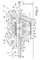
- Figure 1 which refers to a machine 1a for the vacuum packaging or modified atmosphere packaging, with a traditional seal, of products inside preformed tray-like containers 60
- the containers 60 are arranged on the resting contact surface 52 at the loading station 5, which can also act as a station for filling the containers 60 with the products to be packaged.
- the actuation of the chains 50 causes the containers 60 arranged on the resting contact surface 52 to advance until a container or group of containers 60 is positioned on the corresponding supporting pan 18 or 19 arranged inside the packaging chamber 14 or the packaging chamber 15.
- a portion of sealing film 10, 11 is unwound from the corresponding supply spool 34, 35 and arranged between the upper bell 22, 23 and the lower bell 16, 17, ready to be used.
- the lower bell 16, 17 is lifted toward the upper bell 22, 23 so as to lift the corresponding container or group of containers 60 and close the packaging chamber 14, 15.
- the inside of the packaging chamber 14, 15 can be connected simply to a vacuum pump so as to provide the desired degree of vacuum inside the container or group of containers 60 or, sequentially, to a vacuum pump and to a line for supplying a gas or gas mixture in order to modify the atmosphere inside the container or group of containers 60.
- the upper mold part 24, 25 is thus lowered and brought into contact with the lower mold part 20, 21, sealing the sealing film 10, 11 on the rim of the container or containers 60 and cutting the sealing film 10, 11 around the rim of the container or containers 60.
- the lower bell 16, 17 thanks to the actuation of the fluid-operated cylinder 28, 29, is lowered so as to open again the packaging chamber 14, 15.
- the chains 50 are thus actuated again and cause the passage of the packaged container or containers 60 from the packaging station 7 to the unloading station 6, where they are moved away from the machine 1a, for example by means of the conveyor belt 55.
- the two packaging chambers 14, 15 can be equipped with lower mold parts 20, 21 and upper mold parts 24, 25 which are identical, i.e., are provided to be used with a same format of containers 60 so that they can be used simultaneously to double the productivity of the machine when required.
- the two packaging chambers 14, 15 may be equipped with mutually different mold parts, so as to be able to process containers 60 of different formats.
- a single packaging chamber 14 or 15, the one capable of packaging the required format, is used, while the other packaging chamber 15 or 14 is designed to be used as a quick alternative when format change is required.
- the containers 60 to be packaged are arranged on the resting contact surface 52 and are made to advance, thanks to the actuation of the chains 50, toward the packaging station 7.
- the two packaging chambers 14, 15 are used sequentially.
- the containers 60 first pass inside the packaging chamber 14, which is closed, by means of the lifting of the lower bell 16 toward the upper bell 22, which is actuated by means of the actuation of the fluid-operated cylinder 28.
- the desired degree of vacuum is provided inside the container or containers 60, so that the sealing film 10, adequately preheated by the plate 49, adheres to the product, achieving the characteristic "skin" effect.
- the sealing film 10 is then sealed on the rim of the container or containers 60 and cut around the rim of the container or containers 60, in a manner that is similar to the one described with reference to the first embodiment, i.e., by lowering the upper mold part 24 onto the lower mold part 20.
- the packaging chamber 14 is thus opened by actuating the lowering of the lower bell 16 by means of the actuation of the fluid-operated cylinder 28, and the container or containers 60 are arranged at the second packaging chamber 15, which is thus closed by means of the lifting of the lower bell 17, actuating the fluid-operated cylinder 29.
- this packaging chamber 15 is performed the sealing of the sealing film 11 on the rim of the container or containers 60 and the sealing film 11 is cut around the rim of the container or containers 60 by lowering the upper mold part 25 onto the lower mold part 21.
- the packaging chamber 15 is thus opened and the container or containers 60, by actuating the chains 50, are brought into the unloading station 6, where they are moved away from the machine 1b, for example by means of the conveyor belt 55.
- the machine according to the invention is conveniently provided with a control and monitoring element of the programmable electronic type, which controls the operation of the machine.
- control and monitoring element manages, in particular, the advancement of the containers 60 along the advancement direction 4, the opening and closing of the packaging chambers 14, 15 and the actuation of the sealing means 12, 13, as well as the arrangement of portions of sealing film 10, 11 at the corresponding packaging chamber 14, 15.
- a heating plate similar to the heating plate 49 can be provided between the supply spool 35 and the second packaging chamber 15 .
- This constructive variation of the machine according to the invention can be used to perform a packaging with sealing of the "skin" type both in the first packaging chamber 14 and in the second packaging chamber 15.
- the change of format can be performed extremely rapidly by simply selecting the corresponding program in the control and monitoring element that controls the operation of the machine and by simply varying the distance between the lateral guides in order to adjust it to the dimensions of the containers 60.
- the machine according to the invention fully achieves the intended aim, since thanks to the fact that it has at least two packaging chambers, each of which is served by corresponding means for positioning the sealing film which can be used autonomously with respect to those that serve another packaging chamber or chambers, high flexibility in use, capable of meeting the most disparate requirements, is achieved.
- the materials used, as well as the dimensions, may be any according to requirements and to the state of the art.
Abstract
Description
- The present invention relates to a machine for packaging, by sealing with synthetic film, products, particularly food products, in containers such as trays, tubs or the like.
- Machines are known for packaging products, particularly food products, in preformed containers, such as trays, tubs or the like, by means of the application, performed usually by heat-sealing or similar methods, of a synthetic film arranged to close the mouth of the containers.
- Such conventional machines generally comprise a resting contact surface that extends from a station for loading the containers to a packaging station and along which the containers are pushed by way of adapted moving means within lateral guides that delimit laterally the advancement path of the containers. At the packaging station a packaging chamber is generally provided that is composed of a lower bell, which is open upwardly, and an upper bell, which is open downwardly and faces the lower chamber. In the lower bell there is at least one supporting pan for at least one container and a lower mold part that can engage the protruding rim that delimits the mouth of the container or containers to be sealed, whereas in the upper bell there is an upper mold part provided with means for sealing the synthetic film that is arranged between the lower bell and the upper bell. The lower bell can be lifted in order to lift the container toward the upper mold part and to engage the upper bell, delimiting a compartment that is hermetically sealed toward the outside and, according to the type of packaging to be performed, can be connected simply to a vacuum pump (vacuum packaging) or, sequentially, to a vacuum pump and to a line for supplying a gas or a gas mixture (modified atmosphere packaging).
- The sealing film unwinds from a supply spool to a waste winding roll by passing, in the packaging station, between the lower bell and the upper bell.
- The upper mold part can move vertically with respect to the upper bell in order to engage the lower mold part and perform sealing, generally heat-sealing, of the film that passes between the two mold parts.
- When the lower bell has been lifted against the upper bell and the desired degree of vacuum has been reached or the atmosphere has been modified in the compartment delimited by the two bells, the upper mold part, in closing onto the lower mold part, seals the film on the rim that delimits the mouth of the container or containers carried by the lower mold part and cuts the film along the rim of the container or containers.
- Such machines are capable of performing the packaging of a container or a group of containers, as many as can be accommodated inside the packaging chamber.
- Machines for large production runs are also known in which two packaging chambers are provided in the packaging station. In such machines, a same sealing film is used for both packaging chambers and unwinds, similarly to machines with a single packaging chamber, from a supply spool to a waste winding roll, and the two packaging chambers are used simultaneously, obtaining the advantage of doubling the productivity of the machine in comparison to machines with a single packaging chamber.
- Machines of the known type are not devoid of problems and drawbacks.
- In fact, such machines are scarcely flexible in use because when a change of format is required or when the format of the containers to be packaged is changed it is necessary to replace the mold parts, adjust the lateral guides, often also replace the sealing film, retrieve the program in the control and monitoring element that supervises the operation of the machine, and heat the upper mold part or parts, with an expenditure of time and manpower.
- Even greater difficulties are encountered when the sealing operation requires two separate steps in which it is necessary for the machine to work in a different manner, such as for example when packaging with so-called "skin" sealing, followed by a further seal, is required. This type of packaging in fact requires a first step of vacuum packaging with pre-heating of a particular sealing film, so that such film adheres (like a skin) to the product placed in the containers, and then a second step, in which a further sealing of the mouth of the containers by using another type of sealing film without a "skin" effect is performed which, for the sake of simplicity and greater clarity, will be referenced as "traditional sealing".
- In this case, with conventional machines it is necessary to perform the two steps of the packaging on two separate machines, or, if only one machine is available, in two passes on the same machine after replacing the sealing film between the two passes. The double loading of the containers on a same machine or on two separate machines and the replacement of the film in the case of a single machine require the use of manpower and affect significantly the overall production times.
- The aim of the present invention is to solve the problems and overcome the drawbacks described above, by providing a machine that can adapt in an extremely simple and quick way to the several requirements of use.
- Within this aim, an object of the invention is to provide a machine that can pass quickly from the packaging of containers of one format to the packaging of containers of a different format.
- Another object of the invention is to provide a machine that can increase its productivity when required.
- A further object of the invention is to provide a machine that can perform, in a single pass, two distinct packaging steps, as required for example in packaging with a seal of the "skin" type followed by a traditional seal.
- Another object of the invention is to provide a machine that is highly reliable and precise in operation.
- This aim and these and other objects that will become better apparent hereinafter are achieved by a machine for packaging, by sealing with synthetic film, products, particularly food products, in containers such as trays, tubs or the like, comprising means for moving the containers, in which the products to be packaged are arranged, along an advancement direction from a station for loading the containers to a station for unloading the containers, between said loading station and said unloading station there being a packaging station provided with means for positioning a sealing film on the upper side to be sealed of the containers and with means for heat-sealing said sealing film on the containers, characterized in that, in said packaging station, at least two packaging chambers are provided, each of said packaging chambers being served by corresponding means for positioning a sealing film, which can be used autonomously with respect to those that serve another packaging chamber located in said packaging station.
- Further characteristics and advantages of the invention will become better apparent from the description of two preferred but not exclusive embodiments of the machine according to the invention, illustrated by way of non-limiting example in the accompanying drawings, wherein:
-
Figure 1 is a partially sectional schematic view of the machine according to the invention in a first embodiment and with the packaging chambers opened; -
Figure 2 is a partially sectional schematic view of the machine according to the invention in a second embodiment and with the packaging chambers opened; -
Figure 3 is a schematic view of the machine according to the invention, in the second embodiment, with the packaging chambers closed. - With reference to the figures, the machine according to the invention, generally designated in the two embodiments by the
reference numerals structure 2, which is provided with feet for resting on the ground andsupports means 3 for moving thecontainers 60, in which the products to be packaged are arranged, along anadvancement direction 4 from aloading station 5 to anunloading station 6 for thecontainers 60. - Between the
loading station 5 and theunloading station 6 there is apackaging station 7 which is provided withmeans sealing film containers 60 and withmeans film containers 60. - According to the invention, in the
packaging station 7 at least twopackaging chambers packaging chambers corresponding means sealing film packaging chamber packaging station 7. - More particularly, each
packaging chamber lower bell pan lower mold part containers 60 and protrudes outwardly. Thelower mold part containers 60 which it must engage. In practice, the supportingpans lower bell containers 60, correspond to the region or regions delimited by the frame that constitutes thelower mold part lower bell - Each
packaging chamber upper bell lower bell upper mold part lower mold part corresponding sealing film containers 60 arranged at thecorresponding packaging chamber upper mold part upper mold part corresponding sealing film containers 60. - The
upper mold part sealing film containers 60. - Below each
lower bell lower bell lower mold part upper bell packaging chamber lower bell cylinder structure 2 and by means of the upper end of the stem of its piston to the lower side of the correspondinglower bell - Each
upper mold part cylinder upper bell cylinder upper mold part lower mold part - Proximate to each
packaging chamber sensors packaging chamber pans containers 60. Conveniently, thesensors upper bell lower bell packaging chambers lower bells upper bells - For each
packaging chamber lower bell upper bell containers 60 and can be connected, in a per se known manner, to a vacuum pump and/or to a line for supplying a gas or a gas mixture, depending on whether vacuum packaging or modified atmosphere packaging is required. - The means 8, 9 for positioning a
sealing film packaging chambers spool sealing film waste sealing film rollers sealing film supply spool waste winding roll sealing film lower bell upper bell corresponding packaging chamber - More particularly, the
waste winding roll gearmotor film supply spool roller same gearmotor autonomous gearmotor 44, against which apresser roller - Optionally, along the path followed by each
sealing film supply spool corresponding packaging chamber unit sealing film - In the second embodiment of the machine according to the invention, illustrated in
Figures 2 and3 , which refers to a machine for performing packaging with a seal of the "skin" type followed by a traditional seal, between thesupply spool 34 and thefirst packaging chamber 14, i.e. the packaging chamber that is encountered first by thecontainers 60 in their advancement path from theloading station 5 to theunloading station 6, aplate 49 for heating thesealing film - The
means 3 for moving thecontainers 60 comprise a pair ofchains 50 which are arranged side-by-side and laterally, on mutually opposite sides, with respect to a vertical central plane that is parallel to theadvancement direction 4 andtraction elements 51 which are arranged at right angles to theadvancement direction 4 and are fixed to thechains 50. Between theloading station 5 and thepackaging station 7 there is a substantially horizontalresting contact surface 52, which is fixed to the supportingstructure 2. On suchresting contact surface 52 there are, in a per se known manner, lateral guides, not visible in the figures, that delimit laterally the advancement path of thecontainers 60. The distance of such lateral guides can be changed, in a per se known manner, in order to adapt it to the dimensions of thecontainers 60. Thechains 50 engagecorresponding pinions 53, which are supported so as to rotate about their own axes, which are arranged horizontally and are oriented at right angles to theadvancement direction 4, by the supportingstructure 2. Thepinions 53 are arranged so that thechains 50, at the restingcontact surface 52, are arranged with one of their portions laterally and on mutually opposite sides with respect to the resting contact regions of thecontainers 60 on the restingcontact surface 52. At least one of thepinions 53 is actuated with a rotary motion about its own axis by acorresponding gearmotor 54 so as to cause the advancement of thechains 50 along their closed path and thus the advancement of thetraction elements 51, fixed to thechains 50, with consequent advancement of thecontainers 60 from theloading station 5 to theunloading station 6, passing through thepackaging station 7. - Conveniently, at the
unloading station 6, there is the beginning of aconveyor belt 55 by way of which the packagedcontainers 60 are moved away from the machine. - Operation of the machine according to the invention is as follows.
- In the first embodiment, illustrated in
Figure 1 , which refers to amachine 1a for the vacuum packaging or modified atmosphere packaging, with a traditional seal, of products inside preformed tray-like containers 60, thecontainers 60 are arranged on the restingcontact surface 52 at theloading station 5, which can also act as a station for filling thecontainers 60 with the products to be packaged. With the twopackaging chambers Figure 1 , the actuation of thechains 50 causes thecontainers 60 arranged on the restingcontact surface 52 to advance until a container or group ofcontainers 60 is positioned on the corresponding supportingpan packaging chamber 14 or thepackaging chamber 15. From time to time, a portion ofsealing film corresponding supply spool upper bell lower bell cylinder lower bell upper bell containers 60 and close thepackaging chamber packaging chamber containers 60 or, sequentially, to a vacuum pump and to a line for supplying a gas or gas mixture in order to modify the atmosphere inside the container or group ofcontainers 60. Theupper mold part lower mold part sealing film containers 60 and cutting thesealing film containers 60. Finally, thelower bell cylinder packaging chamber chains 50 are thus actuated again and cause the passage of the packaged container orcontainers 60 from thepackaging station 7 to the unloadingstation 6, where they are moved away from themachine 1a, for example by means of theconveyor belt 55. - According to the requirements, the two
packaging chambers lower mold parts upper mold parts containers 60 so that they can be used simultaneously to double the productivity of the machine when required. As an alternative, the twopackaging chambers containers 60 of different formats. In this case, asingle packaging chamber other packaging chamber - In the second embodiment, illustrated in
Figures 2 and3 , which refers to amachine 1b for performing packaging with sealing of the "skin" type followed by a traditional sealing, thecontainers 60 to be packaged are arranged on the restingcontact surface 52 and are made to advance, thanks to the actuation of thechains 50, toward thepackaging station 7. In this second embodiment, the twopackaging chambers - More particularly, the
containers 60 first pass inside thepackaging chamber 14, which is closed, by means of the lifting of thelower bell 16 toward theupper bell 22, which is actuated by means of the actuation of the fluid-operatedcylinder 28. In thepackaging chamber 14 the desired degree of vacuum is provided inside the container orcontainers 60, so that the sealingfilm 10, adequately preheated by theplate 49, adheres to the product, achieving the characteristic "skin" effect. The sealingfilm 10 is then sealed on the rim of the container orcontainers 60 and cut around the rim of the container orcontainers 60, in a manner that is similar to the one described with reference to the first embodiment, i.e., by lowering theupper mold part 24 onto thelower mold part 20. Thepackaging chamber 14 is thus opened by actuating the lowering of thelower bell 16 by means of the actuation of the fluid-operatedcylinder 28, and the container orcontainers 60 are arranged at thesecond packaging chamber 15, which is thus closed by means of the lifting of thelower bell 17, actuating the fluid-operatedcylinder 29. In thispackaging chamber 15 is performed the sealing of the sealingfilm 11 on the rim of the container orcontainers 60 and the sealingfilm 11 is cut around the rim of the container orcontainers 60 by lowering theupper mold part 25 onto thelower mold part 21. Thepackaging chamber 15 is thus opened and the container orcontainers 60, by actuating thechains 50, are brought into the unloadingstation 6, where they are moved away from themachine 1b, for example by means of theconveyor belt 55. - Attention is called to the fact that the
traction elements 51, once the container orcontainers 60 have been arranged on the supporting pan or pans 18, 19 of apackaging chamber chains 50 so as to bring thetraction elements 51 outside the volume of thelower bell lower bell packaging chamber - The machine according to the invention is conveniently provided with a control and monitoring element of the programmable electronic type, which controls the operation of the machine. Such control and monitoring element manages, in particular, the advancement of the
containers 60 along theadvancement direction 4, the opening and closing of thepackaging chambers film packaging chamber - According to a variation of the second embodiment of the machine according to the invention, between the
supply spool 35 and the second packaging chamber 15 a heating plate similar to theheating plate 49 can be provided. This constructive variation of the machine according to the invention can be used to perform a packaging with sealing of the "skin" type both in thefirst packaging chamber 14 and in thesecond packaging chamber 15. - Attention is brought to the fact that in the machine according to the invention, since at least two
packaging chambers film packaging chamber other packaging chamber packaging chambers containers 60 of a same format so as to double the productivity of the machine or to use only one of thepackaging chambers - With the machine according to the invention, when one of the two
packaging chambers containers 60 of a different format, the change of format can be performed extremely rapidly by simply selecting the corresponding program in the control and monitoring element that controls the operation of the machine and by simply varying the distance between the lateral guides in order to adjust it to the dimensions of thecontainers 60. - In practice it has been found that the machine according to the invention fully achieves the intended aim, since thanks to the fact that it has at least two packaging chambers, each of which is served by corresponding means for positioning the sealing film which can be used autonomously with respect to those that serve another packaging chamber or chambers, high flexibility in use, capable of meeting the most disparate requirements, is achieved.
- For the sake of simplicity and greater clarity, the description of the machine according to the invention has been limited to two preferred embodiments, in which two packaging chambers are provided, but it is possible to provide more packaging chambers, each served by corresponding means for positioning a sealing film which can be used autonomously with respect to those that serve another packaging chamber or chambers, without thereby abandoning the scope of protection of the present invention.
- The machine thus conceived is susceptible of numerous modifications and variations, all of which are within the scope of the appended claims; all the details may further be replaced with other technically equivalent elements.
- In practice, the materials used, as well as the dimensions, may be any according to requirements and to the state of the art.
- The disclosures in Italian Patent Application No.
MI2010A000471 - Where technical features mentioned in any claim are followed by reference signs, those reference signs have been included for the sole purpose of increasing the intelligibility of the claims and accordingly such reference signs do not have any limiting effect on the interpretation of each element identified by way of example by such reference signs.
Claims (10)
- A machine for packaging, by sealing with synthetic film, products, particularly food products, in containers such as trays, tubs or the like, comprising means (3) for moving the containers (60), in which the products to be packaged are arranged, along an advancement direction (4) from a station (5) for loading the containers (60) to a station (6) for unloading the containers (60); between said loading station (5) and said unloading station (6) there being a packaging station (7) provided with means (8, 9) for positioning a sealing film (10, 11) on the upper side to be sealed of the containers (60) and with means (12, 13) for heat-sealing said sealing film (10, 11) on the containers (60), characterized in that, in said packaging station (7), at least two packaging chambers (14, 15) are provided, each one of said packaging chambers (14 or 15) being served by corresponding means (8, 9) for positioning a sealing film (10, 11), which can be used autonomously with respect to the ones that serve another packaging chamber (15 or 14) located in said packaging station (7).
- The machine according to claim 1, characterized in that each one of said packaging chambers (14, 15) comprises a lower bell (16, 17), which is open in an upper region, and an upper bell (22, 23), which is open in a lower region and faces said lower bell (16, 17); means (26, 27) being provided for lifting said lower bell (16, 17) toward said upper bell (22, 23) with the corresponding sealing film (10, 11) interposed; said upper bell (22, 23) and said lower bell (16, 17) being mutually engageable in order to delimit, hermetically with respect to the outside, a compartment that is adapted to accommodate said at least one container (60) to be sealed.
- The machine according to claims 1 and 2, characterized in that in the lower bell (16, 17) of each one of said packaging chambers (14, 15) at least one substantially horizontal supporting pan (18, 19) is provided for at least one container (60) to be sealed and a lower mold part (20, 21) that can engage the rim of the mouth of said at least one container (60) arranged on said supporting pan (18, 19); said lower mold (20, 21) being jointly connected to the corresponding lower bell (16, 17) in its translational motion toward or away with respect to the upper bell (22, 23) of said packaging chamber (14, 15) thanks to the action of said lifting means (26, 27).
- The machine according to one or more of the preceding claims, characterized in that in the upper bell (22, 23) of each packaging chamber (14, 15) an upper mold part (24, 25) is provided that faces the lower mold part (20, 21) of the lower bell (16, 17) of said packaging chamber (14, 15) and can engage said lower mold (20, 21) with the corresponding sealing film (10, 11) interposed; said upper mold part (24, 25) being provided with means (12, 13) for heat-sealing the corresponding sealing film (10, 11) on the rim of the mouth of the at least one container (60) engaged by said lower mold part (20, 21).
- The machine according to one or more of the preceding claims, characterized in that said compartment can be connected to a vacuum pump and/ or to a gas supply line.
- The machine according to one or more of the preceding claims, characterized in that said means (8, 9) for positioning a sealing film (10, 11) comprise, for each one of said packaging chambers (14, 15), a spool (34, 35) for supplying the sealing film (10, 11), a roll for winding the waste (36, 37) of sealing film (10, 11), and guiding rollers (38, 39), which define, for said sealing film (10, 11), a path that runs from said supply spool (34, 35) to said waste winding roll (36, 37), said path lying partly between said lower bell (16, 17) and said upper bell (22, 23) of the corresponding packaging chamber (14, 15).
- The machine according to one or more of the preceding claims, characterized in that means (49) for heating the sealing film (10, 11) are provided along said path.
- The machine according to one or more of the preceding claims, characterized in that said means (3) for moving the containers (60) to be packaged from said loading station (5) to said unloading station (6) comprise a pair of chains (50) which are arranged side-by-side and laterally, on mutually opposite sides, with respect to a vertical central plane that is parallel to said advancement direction (4) and traction elements (51) which are arranged at right angles to said advancement direction (4) and are fixed to said chains (50), between said loading station (5) and said packaging station (7) there being a substantially horizontal resting contact surface (52) for the containers (60) and said chains (50) being arranged with one of their portions laterally and on mutually opposite sides with respect to the resting contact regions of the containers (60) on said resting contact surface (52), said traction elements (51) being engageable with said containers (60) on said resting contact surface (52) in order to cause their advancement along said advancement direction (4) from said loading station (5) to said packaging station (7) and from said packaging station (7) to said unloading station (6).
- The machine according to one or more of the preceding claims, characterized in that it comprises a control and monitoring element of the programmable electronic type that is adapted to control the use of said at least two packaging chambers (14, 15) alternately or simultaneously or sequentially according to preset programs.
- The machine according to one or more of the preceding claims, characterized in that in said unloading station (6) a conveyor belt (55) for moving away the packaged containers (60) is provided.
Applications Claiming Priority (1)
| Application Number | Priority Date | Filing Date | Title |
|---|---|---|---|
| IT000471A ITMI20100471A1 (en) | 2010-03-23 | 2010-03-23 | MACHINE TO CARRY OUT THE PACKAGING, BY SEALING WITH SYNTHETIC FILM, OF PRODUCTS, IN PARTICULAR FOOD PRODUCTS, IN CONTAINERS OF THE TYPE OF TRAYS, TRAYS OR SIMILAR, WITH HIGH FLEXIBILITY OF USE. |
Publications (2)
| Publication Number | Publication Date |
|---|---|
| EP2380810A2 true EP2380810A2 (en) | 2011-10-26 |
| EP2380810A3 EP2380810A3 (en) | 2012-02-22 |
Family
ID=43415204
Family Applications (1)
| Application Number | Title | Priority Date | Filing Date |
|---|---|---|---|
| EP11157792A Withdrawn EP2380810A3 (en) | 2010-03-23 | 2011-03-11 | Machine for packaging, by sealing with synthetic film, products, particularly food products, in containers such as trays, tubs or the like, with high flexibility in use |
Country Status (2)
| Country | Link |
|---|---|
| EP (1) | EP2380810A3 (en) |
| IT (1) | ITMI20100471A1 (en) |
Cited By (9)
| Publication number | Priority date | Publication date | Assignee | Title |
|---|---|---|---|---|
| EP2468633A1 (en) * | 2010-12-27 | 2012-06-27 | Multivac Sepp Haggenmüller GmbH & Co. KG | Tray closing machine and method for operating the same |
| ITBO20110718A1 (en) * | 2011-12-15 | 2013-06-16 | So Te Ma Pack S R L | EQUIPMENT FOR REALIZING A RESPECTIVE PACKAGE. |
| WO2013088412A3 (en) * | 2011-12-15 | 2013-09-12 | So.Te.Ma. Pack S.R.L. | An apparatus for making a respective package. |
| EP2644516A1 (en) * | 2012-03-30 | 2013-10-02 | Multivac Sepp Haggenmüller GmbH & Co. KG | Packaging machine with a sealing device |
| WO2014199161A1 (en) * | 2013-06-13 | 2014-12-18 | Ishida Europe Limited | Traysealing apparatus |
| IT201700066109A1 (en) * | 2017-06-14 | 2018-12-14 | Italianpack S R L | PACKAGING MACHINE WITH DRAWING DETECTION SYSTEM AND ITS OPERATING METHOD |
| CN109625465A (en) * | 2018-12-18 | 2019-04-16 | 广州玺明机械科技有限公司 | A kind of food box packaging method, food box sealing machine and food box sealed membrane |
| EP3566956A1 (en) * | 2018-05-10 | 2019-11-13 | PI.CO.TECH S.r.l. | Packaging machine for tray-packaged products |
| WO2022074420A1 (en) * | 2020-10-05 | 2022-04-14 | Maverick International Pty Ltd | Flexible container manufacturing arrangement |
Families Citing this family (1)
| Publication number | Priority date | Publication date | Assignee | Title |
|---|---|---|---|---|
| CN106043766B (en) * | 2016-07-28 | 2018-04-06 | 苏州市盛百威包装设备有限公司 | A kind of PP straps machine |
Family Cites Families (4)
| Publication number | Priority date | Publication date | Assignee | Title |
|---|---|---|---|---|
| WO1994027868A2 (en) * | 1993-05-20 | 1994-12-08 | World Class Packaging Systems, Inc. | Packaging systems for increased food product shelf life |
| DE10237933A1 (en) * | 2002-08-14 | 2004-02-26 | Multivac Sepp Haggenmüller Gmbh & Co. Kg | Packaging machine for food in trays comprises mobile upper and lower sections enclosing chamber for tray, rollers feeding film into chamber, after which it is lifted away from food and sealed to tray at its edges |
| ITBO20060249A1 (en) * | 2006-04-05 | 2007-10-06 | Awax Progettazione | APPARATUS AND MACHINE TO PACK PRODUCT TRAYS IN MODIFIED ATMOSPHERE. |
| DE102006061309A1 (en) * | 2006-12-22 | 2008-07-03 | Jörg von Seggern Maschinenbau GmbH | Method for gas-tight packaging of objects and installation for gas-tight packaging of objects |
-
2010
- 2010-03-23 IT IT000471A patent/ITMI20100471A1/en unknown
-
2011
- 2011-03-11 EP EP11157792A patent/EP2380810A3/en not_active Withdrawn
Non-Patent Citations (1)
| Title |
|---|
| None |
Cited By (11)
| Publication number | Priority date | Publication date | Assignee | Title |
|---|---|---|---|---|
| EP2468633A1 (en) * | 2010-12-27 | 2012-06-27 | Multivac Sepp Haggenmüller GmbH & Co. KG | Tray closing machine and method for operating the same |
| ITBO20110718A1 (en) * | 2011-12-15 | 2013-06-16 | So Te Ma Pack S R L | EQUIPMENT FOR REALIZING A RESPECTIVE PACKAGE. |
| WO2013088412A3 (en) * | 2011-12-15 | 2013-09-12 | So.Te.Ma. Pack S.R.L. | An apparatus for making a respective package. |
| EP2644516A1 (en) * | 2012-03-30 | 2013-10-02 | Multivac Sepp Haggenmüller GmbH & Co. KG | Packaging machine with a sealing device |
| US9650164B2 (en) | 2012-03-30 | 2017-05-16 | Multivac Sepp Haggenmueller Se & Co. Kg | Packaging machine with sealing device |
| WO2014199161A1 (en) * | 2013-06-13 | 2014-12-18 | Ishida Europe Limited | Traysealing apparatus |
| IT201700066109A1 (en) * | 2017-06-14 | 2018-12-14 | Italianpack S R L | PACKAGING MACHINE WITH DRAWING DETECTION SYSTEM AND ITS OPERATING METHOD |
| WO2018229806A1 (en) * | 2017-06-14 | 2018-12-20 | Italianpack S.R.L. | Packaging machine with tray detection system and operating method thereof |
| EP3566956A1 (en) * | 2018-05-10 | 2019-11-13 | PI.CO.TECH S.r.l. | Packaging machine for tray-packaged products |
| CN109625465A (en) * | 2018-12-18 | 2019-04-16 | 广州玺明机械科技有限公司 | A kind of food box packaging method, food box sealing machine and food box sealed membrane |
| WO2022074420A1 (en) * | 2020-10-05 | 2022-04-14 | Maverick International Pty Ltd | Flexible container manufacturing arrangement |
Also Published As
| Publication number | Publication date |
|---|---|
| ITMI20100471A1 (en) | 2011-09-24 |
| EP2380810A3 (en) | 2012-02-22 |
Similar Documents
| Publication | Publication Date | Title |
|---|---|---|
| EP2380810A2 (en) | Machine for packaging, by sealing with synthetic film, products, particularly food products, in containers such as trays, tubs or the like, with high flexibility in use | |
| KR101969738B1 (en) | Device for vacuum packaging, particularly of food products | |
| US3061984A (en) | Packaging machine and method | |
| CN101472729B (en) | Machine for forming, filling and enclosing foam polymer container | |
| US9650164B2 (en) | Packaging machine with sealing device | |
| US10358240B2 (en) | Method for making capsules | |
| AU2010277579A1 (en) | Vacuum skin packaging of a product arranged on a support | |
| EP3880558B1 (en) | Apparatus for packaging capsules under vacuum | |
| US10207451B2 (en) | Thermoform packaging machine with movable mold insert | |
| JP5869360B2 (en) | Bag deaeration and sealing method and apparatus | |
| KR101744755B1 (en) | Vacuum packaging machine combined to package skin | |
| CN205293195U (en) | Thermoforming vacuum packaging machine | |
| US5088268A (en) | Vacuum packaging apparatus | |
| US3456421A (en) | Apparatus for the manufacture of evacuated film packages | |
| KR101574271B1 (en) | A rotary type packing machine | |
| US3195288A (en) | Packaging apparatus | |
| KR101874326B1 (en) | Vacuum packaging mathod of Vacuum packaging machine combined to package skin | |
| US9573337B2 (en) | Deep-drawing packaging machine with lifting device | |
| KR200178707Y1 (en) | Device for packing processed foodstuffs | |
| KR20010100496A (en) | Cutting device of side sealing machine | |
| US20130305661A1 (en) | Vacuum packaging machine |
Legal Events
| Date | Code | Title | Description |
|---|---|---|---|
| AK | Designated contracting states |
Kind code of ref document: A2 Designated state(s): AL AT BE BG CH CY CZ DE DK EE ES FI FR GB GR HR HU IE IS IT LI LT LU LV MC MK MT NL NO PL PT RO RS SE SI SK SM TR |
|
| AX | Request for extension of the european patent |
Extension state: BA ME |
|
| PUAI | Public reference made under article 153(3) epc to a published international application that has entered the european phase |
Free format text: ORIGINAL CODE: 0009012 |
|
| PUAL | Search report despatched |
Free format text: ORIGINAL CODE: 0009013 |
|
| AK | Designated contracting states |
Kind code of ref document: A3 Designated state(s): AL AT BE BG CH CY CZ DE DK EE ES FI FR GB GR HR HU IE IS IT LI LT LU LV MC MK MT NL NO PL PT RO RS SE SI SK SM TR |
|
| AX | Request for extension of the european patent |
Extension state: BA ME |
|
| RIC1 | Information provided on ipc code assigned before grant |
Ipc: B65B 51/14 20060101ALN20120119BHEP Ipc: B65B 59/02 20060101ALI20120119BHEP Ipc: B65B 31/02 20060101ALI20120119BHEP Ipc: B65B 7/16 20060101AFI20120119BHEP |
|
| STAA | Information on the status of an ep patent application or granted ep patent |
Free format text: STATUS: THE APPLICATION IS DEEMED TO BE WITHDRAWN |
|
| 18D | Application deemed to be withdrawn |
Effective date: 20120823 |