EP2378691B1 - Method and apparatus for mapping uplink control information - Google Patents
Method and apparatus for mapping uplink control information Download PDFInfo
- Publication number
- EP2378691B1 EP2378691B1 EP11162372.4A EP11162372A EP2378691B1 EP 2378691 B1 EP2378691 B1 EP 2378691B1 EP 11162372 A EP11162372 A EP 11162372A EP 2378691 B1 EP2378691 B1 EP 2378691B1
- Authority
- EP
- European Patent Office
- Prior art keywords
- subset
- layers
- codeword transmission
- base station
- mcs
- Prior art date
- Legal status (The legal status is an assumption and is not a legal conclusion. Google has not performed a legal analysis and makes no representation as to the accuracy of the status listed.)
- Active
Links
- 238000000034 method Methods 0.000 title claims description 32
- 238000013507 mapping Methods 0.000 title claims description 17
- 230000005540 biological transmission Effects 0.000 claims description 96
- 101000741965 Homo sapiens Inactive tyrosine-protein kinase PRAG1 Proteins 0.000 claims description 14
- 102100038659 Inactive tyrosine-protein kinase PRAG1 Human genes 0.000 claims description 14
- 238000004891 communication Methods 0.000 description 13
- 125000004122 cyclic group Chemical group 0.000 description 7
- 238000010586 diagram Methods 0.000 description 6
- 238000013459 approach Methods 0.000 description 4
- 238000012986 modification Methods 0.000 description 2
- 230000004048 modification Effects 0.000 description 2
- 101100465000 Mus musculus Prag1 gene Proteins 0.000 description 1
- 230000002776 aggregation Effects 0.000 description 1
- 238000004220 aggregation Methods 0.000 description 1
- 238000004364 calculation method Methods 0.000 description 1
- 239000000969 carrier Substances 0.000 description 1
- 238000006243 chemical reaction Methods 0.000 description 1
- 238000000794 confocal Raman spectroscopy Methods 0.000 description 1
- 238000011500 cytoreductive surgery Methods 0.000 description 1
- 230000001419 dependent effect Effects 0.000 description 1
- 239000000945 filler Substances 0.000 description 1
- 230000007774 longterm Effects 0.000 description 1
- 239000011159 matrix material Substances 0.000 description 1
- 239000000203 mixture Substances 0.000 description 1
- 238000012545 processing Methods 0.000 description 1
- 230000008054 signal transmission Effects 0.000 description 1
- 230000011664 signaling Effects 0.000 description 1
- 238000001228 spectrum Methods 0.000 description 1
Images


Classifications
-
- H—ELECTRICITY
- H04—ELECTRIC COMMUNICATION TECHNIQUE
- H04L—TRANSMISSION OF DIGITAL INFORMATION, e.g. TELEGRAPHIC COMMUNICATION
- H04L5/00—Arrangements affording multiple use of the transmission path
- H04L5/003—Arrangements for allocating sub-channels of the transmission path
- H04L5/0053—Allocation of signaling, i.e. of overhead other than pilot signals
- H04L5/0057—Physical resource allocation for CQI
-
- H—ELECTRICITY
- H04—ELECTRIC COMMUNICATION TECHNIQUE
- H04B—TRANSMISSION
- H04B7/00—Radio transmission systems, i.e. using radiation field
- H04B7/02—Diversity systems; Multi-antenna system, i.e. transmission or reception using multiple antennas
- H04B7/04—Diversity systems; Multi-antenna system, i.e. transmission or reception using multiple antennas using two or more spaced independent antennas
- H04B7/0413—MIMO systems
- H04B7/0456—Selection of precoding matrices or codebooks, e.g. using matrices antenna weighting
-
- H—ELECTRICITY
- H04—ELECTRIC COMMUNICATION TECHNIQUE
- H04L—TRANSMISSION OF DIGITAL INFORMATION, e.g. TELEGRAPHIC COMMUNICATION
- H04L1/00—Arrangements for detecting or preventing errors in the information received
- H04L1/0001—Systems modifying transmission characteristics according to link quality, e.g. power backoff
- H04L1/0023—Systems modifying transmission characteristics according to link quality, e.g. power backoff characterised by the signalling
- H04L1/0028—Formatting
- H04L1/0031—Multiple signaling transmission
-
- H—ELECTRICITY
- H04—ELECTRIC COMMUNICATION TECHNIQUE
- H04B—TRANSMISSION
- H04B7/00—Radio transmission systems, i.e. using radiation field
- H04B7/02—Diversity systems; Multi-antenna system, i.e. transmission or reception using multiple antennas
- H04B7/04—Diversity systems; Multi-antenna system, i.e. transmission or reception using multiple antennas using two or more spaced independent antennas
- H04B7/0413—MIMO systems
- H04B7/0456—Selection of precoding matrices or codebooks, e.g. using matrices antenna weighting
- H04B7/0486—Selection of precoding matrices or codebooks, e.g. using matrices antenna weighting taking channel rank into account
-
- H—ELECTRICITY
- H04—ELECTRIC COMMUNICATION TECHNIQUE
- H04B—TRANSMISSION
- H04B7/00—Radio transmission systems, i.e. using radiation field
- H04B7/02—Diversity systems; Multi-antenna system, i.e. transmission or reception using multiple antennas
- H04B7/04—Diversity systems; Multi-antenna system, i.e. transmission or reception using multiple antennas using two or more spaced independent antennas
- H04B7/06—Diversity systems; Multi-antenna system, i.e. transmission or reception using multiple antennas using two or more spaced independent antennas at the transmitting station
- H04B7/0613—Diversity systems; Multi-antenna system, i.e. transmission or reception using multiple antennas using two or more spaced independent antennas at the transmitting station using simultaneous transmission
- H04B7/0615—Diversity systems; Multi-antenna system, i.e. transmission or reception using multiple antennas using two or more spaced independent antennas at the transmitting station using simultaneous transmission of weighted versions of same signal
- H04B7/0619—Diversity systems; Multi-antenna system, i.e. transmission or reception using multiple antennas using two or more spaced independent antennas at the transmitting station using simultaneous transmission of weighted versions of same signal using feedback from receiving side
- H04B7/0621—Feedback content
- H04B7/0623—Auxiliary parameters, e.g. power control [PCB] or not acknowledged commands [NACK], used as feedback information
-
- H—ELECTRICITY
- H04—ELECTRIC COMMUNICATION TECHNIQUE
- H04B—TRANSMISSION
- H04B7/00—Radio transmission systems, i.e. using radiation field
- H04B7/02—Diversity systems; Multi-antenna system, i.e. transmission or reception using multiple antennas
- H04B7/04—Diversity systems; Multi-antenna system, i.e. transmission or reception using multiple antennas using two or more spaced independent antennas
- H04B7/06—Diversity systems; Multi-antenna system, i.e. transmission or reception using multiple antennas using two or more spaced independent antennas at the transmitting station
- H04B7/0613—Diversity systems; Multi-antenna system, i.e. transmission or reception using multiple antennas using two or more spaced independent antennas at the transmitting station using simultaneous transmission
- H04B7/0615—Diversity systems; Multi-antenna system, i.e. transmission or reception using multiple antennas using two or more spaced independent antennas at the transmitting station using simultaneous transmission of weighted versions of same signal
- H04B7/0619—Diversity systems; Multi-antenna system, i.e. transmission or reception using multiple antennas using two or more spaced independent antennas at the transmitting station using simultaneous transmission of weighted versions of same signal using feedback from receiving side
- H04B7/0621—Feedback content
- H04B7/063—Parameters other than those covered in groups H04B7/0623 - H04B7/0634, e.g. channel matrix rank or transmit mode selection
-
- H—ELECTRICITY
- H04—ELECTRIC COMMUNICATION TECHNIQUE
- H04B—TRANSMISSION
- H04B7/00—Radio transmission systems, i.e. using radiation field
- H04B7/02—Diversity systems; Multi-antenna system, i.e. transmission or reception using multiple antennas
- H04B7/04—Diversity systems; Multi-antenna system, i.e. transmission or reception using multiple antennas using two or more spaced independent antennas
- H04B7/06—Diversity systems; Multi-antenna system, i.e. transmission or reception using multiple antennas using two or more spaced independent antennas at the transmitting station
- H04B7/0613—Diversity systems; Multi-antenna system, i.e. transmission or reception using multiple antennas using two or more spaced independent antennas at the transmitting station using simultaneous transmission
- H04B7/0615—Diversity systems; Multi-antenna system, i.e. transmission or reception using multiple antennas using two or more spaced independent antennas at the transmitting station using simultaneous transmission of weighted versions of same signal
- H04B7/0619—Diversity systems; Multi-antenna system, i.e. transmission or reception using multiple antennas using two or more spaced independent antennas at the transmitting station using simultaneous transmission of weighted versions of same signal using feedback from receiving side
- H04B7/0621—Feedback content
- H04B7/0632—Channel quality parameters, e.g. channel quality indicator [CQI]
-
- H—ELECTRICITY
- H04—ELECTRIC COMMUNICATION TECHNIQUE
- H04L—TRANSMISSION OF DIGITAL INFORMATION, e.g. TELEGRAPHIC COMMUNICATION
- H04L1/00—Arrangements for detecting or preventing errors in the information received
- H04L1/004—Arrangements for detecting or preventing errors in the information received by using forward error control
- H04L1/0072—Error control for data other than payload data, e.g. control data
- H04L1/0073—Special arrangements for feedback channel
-
- H—ELECTRICITY
- H04—ELECTRIC COMMUNICATION TECHNIQUE
- H04L—TRANSMISSION OF DIGITAL INFORMATION, e.g. TELEGRAPHIC COMMUNICATION
- H04L1/00—Arrangements for detecting or preventing errors in the information received
- H04L1/12—Arrangements for detecting or preventing errors in the information received by using return channel
- H04L1/16—Arrangements for detecting or preventing errors in the information received by using return channel in which the return channel carries supervisory signals, e.g. repetition request signals
- H04L1/18—Automatic repetition systems, e.g. Van Duuren systems
- H04L1/1829—Arrangements specially adapted for the receiver end
- H04L1/1861—Physical mapping arrangements
-
- H—ELECTRICITY
- H04—ELECTRIC COMMUNICATION TECHNIQUE
- H04L—TRANSMISSION OF DIGITAL INFORMATION, e.g. TELEGRAPHIC COMMUNICATION
- H04L25/00—Baseband systems
- H04L25/02—Details ; arrangements for supplying electrical power along data transmission lines
- H04L25/03—Shaping networks in transmitter or receiver, e.g. adaptive shaping networks
- H04L25/03891—Spatial equalizers
- H04L25/03898—Spatial equalizers codebook-based design
- H04L25/03929—Spatial equalizers codebook-based design with layer mapping, e.g. codeword-to layer design
-
- H—ELECTRICITY
- H04—ELECTRIC COMMUNICATION TECHNIQUE
- H04L—TRANSMISSION OF DIGITAL INFORMATION, e.g. TELEGRAPHIC COMMUNICATION
- H04L5/00—Arrangements affording multiple use of the transmission path
- H04L5/0001—Arrangements for dividing the transmission path
- H04L5/0014—Three-dimensional division
- H04L5/0023—Time-frequency-space
-
- H—ELECTRICITY
- H04—ELECTRIC COMMUNICATION TECHNIQUE
- H04L—TRANSMISSION OF DIGITAL INFORMATION, e.g. TELEGRAPHIC COMMUNICATION
- H04L5/00—Arrangements affording multiple use of the transmission path
- H04L5/0001—Arrangements for dividing the transmission path
- H04L5/0026—Division using four or more dimensions
-
- H—ELECTRICITY
- H04—ELECTRIC COMMUNICATION TECHNIQUE
- H04L—TRANSMISSION OF DIGITAL INFORMATION, e.g. TELEGRAPHIC COMMUNICATION
- H04L5/00—Arrangements affording multiple use of the transmission path
- H04L5/003—Arrangements for allocating sub-channels of the transmission path
- H04L5/0048—Allocation of pilot signals, i.e. of signals known to the receiver
-
- H—ELECTRICITY
- H04—ELECTRIC COMMUNICATION TECHNIQUE
- H04L—TRANSMISSION OF DIGITAL INFORMATION, e.g. TELEGRAPHIC COMMUNICATION
- H04L5/00—Arrangements affording multiple use of the transmission path
- H04L5/003—Arrangements for allocating sub-channels of the transmission path
- H04L5/0053—Allocation of signaling, i.e. of overhead other than pilot signals
- H04L5/0055—Physical resource allocation for ACK/NACK
-
- H—ELECTRICITY
- H04—ELECTRIC COMMUNICATION TECHNIQUE
- H04L—TRANSMISSION OF DIGITAL INFORMATION, e.g. TELEGRAPHIC COMMUNICATION
- H04L1/00—Arrangements for detecting or preventing errors in the information received
- H04L1/12—Arrangements for detecting or preventing errors in the information received by using return channel
- H04L1/16—Arrangements for detecting or preventing errors in the information received by using return channel in which the return channel carries supervisory signals, e.g. repetition request signals
- H04L1/1607—Details of the supervisory signal
- H04L1/1671—Details of the supervisory signal the supervisory signal being transmitted together with control information
Definitions
- the present application relates generally to wireless communications and, more specifically, to a method and system for indicating one or more enabled transport blocks.
- Orthogonal Frequency Division Multiplexing is adopted as a downlink (DL) transmission scheme.
- Data-control multiplexing concatenates CQI/PMI (control) bits with the data (UL-SCH) bits where CQI/PMI is placed before the data bits. In addition, it ensures that none of the control and data bits are mapped onto the same QAM symbol.
- Channel interleaving combines the output of data-control multiplexing, HARQ-ACK, and RI to implement a time-first mapping in conjunction with the resource element (RE) mapping. The end result ensures that the QAM-modulated HARQ-ACK symbols are placed around the DMRS with the RI symbols placed around the HARQ-ACK symbols.
- control information CQI/PMI, HARQ-ACK, RI
- the selected CW should be the one with better channel quality.
- the CW there are several alternatives to signal the UE the CW to be used, (1) semi-statically configured by higher layer; (2) signaled dynamically via PDCCH; (3) implicitly linked to MCS; or (4) simply fix the selected CW to the first CW.
- Option 2 Two CWs. With this option, both CWs are selected to transmit the UCI. In order to get the whole control information, eNB should detect the UCI on both CW correctly.
- a base station includes a transmit path circuitry configured to transmit an uplink grant to a subscriber station, the uplink grant indicating a first modulation and coding scheme (MCS) value for a first codeword transmission and a second MCS value for a second codeword transmission.
- the base station also includes a receive path circuitry configured to receive a multiple-input multiple-output (MIMO) uplink subframe from the subscriber station, the MIMO uplink subframe having a first subset of layers used for the first codeword transmission and a second subset of layers used for the second codeword transmission.
- MCS modulation and coding scheme
- Acknowledgement/negative acknowledgement (ACK/NACK) information and rank indication (RI) information are mapped onto both the first subset of layers and the second subset of layers, and channel quality information (CQI) is only mapped onto either the first subset of layers or the second subset of layers.
- ACK/NACK Acknowledgement/negative acknowledgement
- RI rank indication
- CQI channel quality information
- a method of operating a base station includes transmitting an uplink grant to a subscriber station, the uplink grant indicating a first modulation and coding scheme (MCS) value for a first codeword transmission and a second MCS value for a second codeword transmission.
- the method also includes receiving a multiple-input multiple-output (MIMO) uplink subframe from the subscriber station, the MIMO uplink subframe having a first subset of layers used for the first codeword transmission and a second subset of layers used for the second codeword transmission.
- MCS modulation and coding scheme
- Acknowledgement/negative acknowledgement (ACK/NACK) information and rank indication (RI) information are mapped onto both the first subset of layers and the second subset of layers, and channel quality information (CQI) is only mapped onto either the first subset of layers or the second subset of layers.
- ACK/NACK Acknowledgement/negative acknowledgement
- RI rank indication
- CQI channel quality information
- a subscriber station includes a receive path circuitry configured to receive an uplink grant from a base station, the uplink grant indicating a first modulation and coding scheme (MCS) value for a first codeword transmission and a second MCS value for a second codeword transmission.
- the subscriber station also includes a transmit path circuitry configured to generate a multiple-input multiple-output (MIMO) uplink subframe having a first subset of layers used for the first codeword transmission and a second subset of layers used for the second codeword transmission.
- MCS modulation and coding scheme
- the transmit path circuitry also is configured to map acknowledgement/negative acknowledgement (ACK/NACK) information and rank indication (RI) information onto both the first subset of layers and the second subset of layers, map channel quality information (CQI) only onto either the first subset of layers or the second subset of layers, and transmit the MIMO uplink subframe to the base station.
- ACK/NACK acknowledgement/negative acknowledgement
- RI rank indication
- CQI map channel quality information
- a method of operating a subscriber station includes receiving an uplink grant from a base station, the uplink grant indicating a first modulation and coding scheme (MCS) value for a first codeword transmission and a second MCS value for a second codeword transmission.
- MCS modulation and coding scheme
- the method also includes generating a multiple-input multiple-output (MIMO) uplink subframe having a first subset of layers used for the first codeword transmission and a second subset of layers used for the second codeword transmission, mapping acknowledgement/negative acknowledgement (ACK/NACK) information and rank indication (RI) information onto both the first subset of layers and the second subset of layers; mapping channel quality information (CQI) only onto either the first subset of layers or the second subset of layers, and transmitting the MIMO uplink subframe to the base station.
- MIMO multiple-input multiple-output
- FIGURES 1 through 9 discussed below, and the various embodiments used to describe the principles of the present disclosure in this patent document are by way of illustration only and should not be construed in any way to limit the scope of the disclosure. Those skilled in the art will understand that the principles of the present disclosure may be implemented in any suitably arranged wireless communication system.
- LTE terms “node B”, “enhanced node B”, and “eNodeB” are other terms for “base station” used below.
- LTE term “user equipment” or “UE” is another term for “subscriber station” used below.
- FIGURE 1 illustrates exemplary wireless network 100, which transmits messages according to the principles of the present disclosure.
- wireless network 100 includes base station (BS) 101, base station (BS) 102, base station (BS) 103, and other similar base stations (not shown).
- Base station 101 is in communication with Internet 130 or a similar IP-based network (not shown).
- Base station 102 provides wireless broadband access to Internet 130 to a first plurality of subscriber stations within coverage area 120 of base station 102.
- the first plurality of subscriber stations includes subscriber station 111, which may be located in a small business (SB), subscriber station 112, which may be located in an enterprise (E), subscriber station 113, which may be located in a WiFi hotspot (HS), subscriber station 114, which may be located in a first residence (R), subscriber station 115, which may be located in a second residence (R), and subscriber station 116, which may be a mobile device (M), such as a cell phone, a wireless laptop, a wireless PDA, or the like.
- SB small business
- E enterprise
- subscriber station 113 which may be located in a WiFi hotspot (HS)
- subscriber station 114 which may be located in a first residence (R)
- subscriber station 115 which may be located in a second residence (R)
- subscriber station 116 which may be a mobile device
- Base station 103 provides wireless broadband access to Internet 130 to a second plurality of subscriber stations within coverage area 125 of base station 103.
- the second plurality of subscriber stations includes subscriber station 115 and subscriber station 116.
- base stations 101-103 may communicate with each other and with subscriber stations 111-116 using OFDM or OFDMA techniques.
- wireless network 100 may provide wireless broadband access to additional subscriber stations. It is noted that subscriber station 115 and subscriber station 116 are located on the edges of both coverage area 120 and coverage area 125. Subscriber station 115 and subscriber station 116 each communicate with both base station 102 and base station 103 and may be said to be operating in handoff mode, as known to those of skill in the art.
- Subscriber stations 111-116 may access voice, data, video, video conferencing, and/or other broadband services via Internet 130.
- one or more of subscriber stations 111-116 may be associated with an access point (AP) of a WiFi WLAN.
- Subscriber station 116 may be any of a number of mobile devices, including a wireless-enabled laptop computer, personal data assistant, notebook, handheld device, or other wireless-enabled device.
- Subscriber stations 114 and 115 may be, for example, a wireless-enabled personal computer (PC), a laptop computer, a gateway, or another device.
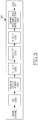
- FIGURE 2 is a high-level diagram of an orthogonal frequency division multiple access (OFDMA) transmit path 200.
- FIGURE 3 is a high-level diagram of an orthogonal frequency division multiple access (OFDMA) receive path 300.
- the OFDMA transmit path 200 is implemented in base station (BS) 102 and the OFDMA receive path 300 is implemented in subscriber station (SS) 116 for the purposes of illustration and explanation only.
- BS base station
- SS subscriber station
- the OFDMA receive path 300 may also be implemented in BS 102 and the OFDMA transmit path 200 may be implemented in SS 116.
- the transmit path 200 in BS 102 comprises a channel coding and modulation block 205, a serial-to-parallel (S-to-P) block 210, a Size N Inverse Fast Fourier Transform (IFFT) block 215, a parallel-to-serial (P-to-S) block 220, an add cyclic prefix block 225, an up-converter (UC) 230, a reference signal multiplexer 290, and a reference signal allocator 295.
- S-to-P serial-to-parallel
- IFFT Inverse Fast Fourier Transform
- P-to-S parallel-to-serial
- UC up-converter
- UC up-converter
- reference signal multiplexer 290 a reference signal allocator 295.
- the receive path 300 in SS 116 comprises a down-converter (DC) 255, a remove cyclic prefix block 260, a serial-to-parallel (S-to-P) block 265, a Size N Fast Fourier Transform (FFT) block 270, a parallel-to-serial (P-to-S) block 275, and a channel decoding and demodulation block 280.
- DC down-converter
- S-to-P serial-to-parallel
- FFT Size N Fast Fourier Transform
- P-to-S parallel-to-serial
- FIGURES 2 and 3 may be implemented in software while other components may be implemented by configurable hardware or a mixture of software and configurable hardware.
- the FFT blocks and the IFFT blocks described in the present disclosure document may be implemented as configurable software algorithms, where the value of Size N may be modified according to the implementation.
- the present disclosure is directed to an embodiment that implements the Fast Fourier Transform and the Inverse Fast Fourier Transform, this is by way of illustration only and should not be construed to limit the scope of the disclosure. It will be appreciated that in an alternate embodiment of the disclosure, the Fast Fourier Transform functions and the Inverse Fast Fourier Transform functions may easily be replaced by Discrete Fourier Transform (DFT) functions and Inverse Discrete Fourier Transform (IDFT) functions, respectively.
- DFT Discrete Fourier Transform
- IDFT Inverse Discrete Fourier Transform
- the value of the N variable may be any integer number (i.e., 1, 2, 3, 4, etc.), while for FFT and IFFT functions, the value of the N variable may be any integer number that is a power of two (i.e., 1, 2, 4, 8, 16, etc.).
- channel coding and modulation block 205 receives a set of information bits, applies coding (e.g., Turbo coding) and modulates (e.g., QPSK, QAM) the input bits to produce a sequence of frequency-domain modulation symbols.
- Serial-to-parallel block 210 converts (i.e., de-multiplexes) the serial modulated symbols to parallel data to produce N parallel symbol streams where N is the IFFT/FFT size used in BS 102 and SS 116.
- Size N IFFT block 215 then performs an IFFT operation on the N parallel symbol streams to produce time-domain output signals.
- Parallel-to-serial block 220 converts (i.e., multiplexes) the parallel time-domain output symbols from Size N IFFT block 215 to produce a serial time-domain signal.
- Add cyclic prefix block 225 then inserts a cyclic prefix to the time-domain signal.
- up-converter 230 modulates (i.e., up-converts) the output of add cyclic prefix block 225 to RF frequency for transmission via a wireless channel.
- the signal may also be filtered at baseband before conversion to RF frequency.
- reference signal multiplexer is operable to multiplex the reference signals using code division multiplexing (CDM) or time/frequency division multiplexing (TFDM).
- Reference signal allocator is operable to dynamically allocate reference signals in an OFDM signal in accordance with the methods and system disclosed in the present disclosure.
- the transmitted RF signal arrives at SS 116 after passing through the wireless channel and reverse operations performed at BS 102.
- Down-converter 255 down-converts the received signal to baseband frequency and remove cyclic prefix block 260 removes the cyclic prefix to produce the serial time-domain baseband signal.
- Serial-to-parallel block 265 converts the time-domain baseband signal to parallel time domain signals.
- Size N FFT block 270 then performs an FFT algorithm to produce N parallel frequency-domain signals.
- Parallel-to-serial block 275 converts the parallel frequency-domain signals to a sequence of modulated data symbols.
- Channel decoding and demodulation block 280 demodulates and then decodes the modulated symbols to recover the original input data stream.
- Each of base stations 101-103 may implement a transmit path that is analogous to transmitting in the downlink to subscriber stations 111-116 and may implement a receive path that is analogous to receiving in the uplink from subscriber stations 111-116.
- each one of subscriber stations 111-116 may implement a transmit path corresponding to the architecture for transmitting in the uplink to base stations 101-103 and may implement a receive path corresponding to the architecture for receiving in the downlink from base stations 101-103.
- the total bandwidth in an OFDM system is divided into narrowband frequency units called subcarriers.
- the number of subcarriers is equal to the FFT/IFFT size N used in the system.
- the number of subcarriers used for data is less than N because some subcarriers at the edge of the frequency spectrum are reserved as guard subcarriers. In general, no information is transmitted on guard subcarriers.
- the transmitted signal in each downlink (DL) slot of a resource block is described by a resource grid of N RB DL N sc RB subcarriers and N symb DL OFDM symbols.
- the quantity N RB DL depends on the downlink transmission bandwidth configured in the cell and fulfills N RB min , DL ⁇ N RB DL ⁇ N RB max , DL , where N RB min , DL and N RB max , DL are the smallest and largest downlink bandwidth, respectively, supported.
- subcarriers are considered the smallest elements that are capable of being modulated.
- Resource element ( k,l ) on antenna port p corresponds to the complex value a k , l p . If there is no risk for confusion or no particular antenna port is specified, the index p may be dropped.
- DL reference signals In LTE, DL reference signals (RSs) are used for two purposes. First, UEs measure channel quality information (CQI), rank information (RI) and precoder matrix information (PMI) using DL RSs. Second, each UE demodulates the DL transmission signal intended for itself using the DL RSs.
- DL RSs are divided into three categories: cell-specific RSs, multi-media broadcast over a single frequency network (MBSFN) RSs, and UE-specific RSs or dedicated RSs (DRSs).
- Cell-specific reference signals are transmitted in all downlink subframes in a cell supporting non-MBSFN transmission. If a subframe is used for transmission with MBSFN, only the first a few (0, 1 or 2) OFDM symbols in a subframe can be used for transmission of cell-specific reference symbols.
- the notation R p is used to denote a resource element used for reference signal transmission on antenna port p .
- UE-specific reference signals (or dedicated RS: DRS) are supported for single-antenna-port transmission on the Physical Downlink Shared Channel (PDSCH) and are transmitted on antenna port 5.
- PDSCH Physical Downlink Shared Channel
- the UE is informed by higher layers whether the UE-specific reference signal is present and is a valid phase reference for PDSCH demodulation or not.
- UE-specific reference signals are transmitted only on the resource blocks upon which the corresponding PDSCH is mapped.
- the time resources of an LTE system are partitioned into 10 msec frames, and each frame is further partitioned into 10 subframes of one msec duration each.
- a subframe is divided into two time slots, each of which spans 0.5 msec.
- a subframe is partitioned in the frequency domain into multiple resource blocks (RBs), where an RB is composed of 12 subcarriers.
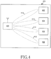
- FIGURE 4 illustrates a diagram 400 of a base station 420 in communication with a plurality of mobile stations 402, 404, 406, and 408 according to an embodiment of this disclosure.
- base station 420 simultaneously communicates with multiple of mobile stations through the use of multiple antenna beams, each antenna beam is formed toward its intended mobile station at the same time and same frequency.
- Base station 420 and mobile stations 402, 404, 406, and 408 are employing multiple antennas for transmission and reception of radio wave signals.
- the radio wave signals can be Orthogonal Frequency Division Multiplexing (OFDM) signals.
- base station 420 performs simultaneous beamforming through a plurality of transmitters to each mobile station. For instance, base station 420 transmits data to mobile station 402 through a beamformed signal 410, data to mobile station 404 through a beamformed signal 412, data to mobile station 406 through a beamformed signal 414, and data to mobile station 408 through a beamformed signal 416. In some embodiments of this disclosure, base station 420 is capable of simultaneously beamforming to the mobile stations 402, 404, 406, and 408. In some embodiments, each beamformed signal is formed toward its intended mobile station at the same time and the same frequency. For the purpose of clarity, the communication from a base station to a mobile station may also be referred to as downlink communication, and the communication from a mobile station to a base station may be referred to as uplink communication.
- Base station 420 and mobile stations 402, 404, 406, and 408 employ multiple antennas for transmitting and receiving wireless signals.
- the wireless signals may be radio wave signals, and the wireless signals may use any transmission scheme known to one skilled in the art, including an Orthogonal Frequency Division Multiplexing (OFDM) transmission scheme.
- OFDM Orthogonal Frequency Division Multiplexing
- Mobile stations 402, 404, 406, and 408 may be any device that is capable receiving wireless signals. Examples of mobile stations 402, 404, 406, and 408 include, but are not limited to, a personal data assistant (PDA), laptop, mobile telephone, handheld device, or any other device that is capable of receiving the beamformed transmissions.
- PDA personal data assistant
- a MIMO system can be implemented with the schemes of spatial multiplexing, a transmit/receive beamforming, or transmit/receive diversity.
- multi-user MIMO is a communication scenario where a base station with multiple transmit antennas can simultaneously communicate with multiple mobile stations through the use of multi-user beamforming schemes such as Spatial Division Multiple Access (SDMA) to improve the capacity and reliability of a wireless communication channel.
- SDMA Spatial Division Multiple Access
- FIGURE 5 illustrates an SDMA scheme according to an embodiment of this disclosure.
- base station 420 is equipped with 8 transmit antennas while mobile stations 402, 404, 406, and 408 are each equipped two antennas.
- base station 420 has eight transmit antennas.
- Each of the transmit antennas transmits one of beamformed signals 410, 502, 504, 412, 414, 506, 416, and 508.
- mobile station 402 receives beamformed transmissions 410 and 502
- mobile station 404 receives beamformed transmissions 504 and 412
- mobile station 406 receives beamformed transmissions 506 and 414
- mobile station 408 receives beamformed transmissions 508 and 416.
- base station 420 Since base station 420 has eight transmit antenna beams (each antenna beams one stream of data streams), eight streams of beamformed data can be formed at base station 420. Each mobile station can potentially receive up to 2 streams (beams) of data in this example. If each of the mobile stations 402, 404, 406, and 408 was limited to receive only a single stream (beam) of data, instead of multiple streams simultaneously, this would be multi-user beamforming (i.e., MU-BF).
- MU-BF multi-user beamforming
- FIGURE 6 illustrates a physical uplink shared channel (PUSCH) transmission chain 600 according to an embodiment of this disclosure.
- PUSCH physical uplink shared channel
- FIGURE 6 illustrates an N layer transmission on an Nt transmit antenna UE.
- FIGURE 6 illustrates the mapping of the outputs of N Discrete Fourier Transform (DFT) precoding units 601-1 to 601-N to a contiguous set of subcarriers at inverse fast Fourier transform (IFFT) units 603-1 to 603-N.
- DFT Discrete Fourier Transform
- IFFT inverse fast Fourier transform
- One of the key components of the PUSCH transmission chain 600 is the data/control multiplexing function implemented in a data/control multiplexing unit 605, which is fully specified in 3GPP TS 36.212 v 8.5.0, "E-UTRA, Multiplexing and Channel Coding", Dec. 2008.
- the layer mapping is performed before DFT precoding, so that the data and control information are properly multiplexed and interleaved.
- the transmit precoding is performed between the DFT precoding units 601-1 to 601-N and the IFFT unit 603 to transform, on a per-subcarrier basic, an N dimension signal at the output of the DFT precoding units 601-1 to 601-N to an Nt dimensional signal as an input to the IFFT units 603-1 to 603-N.
- the subcarrier mapping at the input of the IFFT units 603-1 to 603-N can include non-contiguous segments of subcarriers.
- all the uplink control information (including CQI, RI and A/N bits) is carried on only one of the layers, with the following ways of choosing a particular layer for carrying the uplink control information.
- the total number of transmission layers is denoted as N.
- the layer that has the largest MCS value is selected to carry the uplink control information such as CQI, RI and A/N.
- the MCS values are typically carried in the UL schedule assignment grant (sent by the eNodeB to the UE) and ,therefore, are known at the UE at the time of this data and control transmission.
- the control region size is defined as the number of resource elements.
- the first layer is select to carry the uplink control information such as the CQI, RI and A/N.
- the uplink control information such as the CQI, RI and A/N.
- This selection of a layer could also be explicitly signaled in the uplink scheduling grant as an additional control field, using either DCI format 0 or some other uplink grant DCI format.
- control regions CQI, RI, A/N
- UCI UCI uplink control information
- MCS MCS value associated with the layer on which the control regions are transmitted
- a higher layer signaled offset The exact calculation of control region sizes is similar to what has already specified in 3GPP LTE standard 3GPP TS 36.212 v 8.5.0, "E-UTRA, Multiplexing and Channel coding", Dec 2008 .
- Equation 1 Equation 1 below:
- Equation 2 the control region equation for CQI bits is shown in Equation 2 below:
- Equations 1 and 2 can be amended as shown in Equations 3 and 4, respectively, below:
- the uplink control information is mapped/allocated onto a subset of the N layers being transmitted on the uplink in a MIMO uplink subframe.
- the size of the subset, Ns could be less than or equal to the total number of layers, which is denoted by N.
- the layers used for uplink control transmission could be known at the UE according to one of the following methods.
- the subset of layers used for uplink control information could also be explicitly signaled in the uplink scheduling grant as an additional control field, using either DCI format 0 or some other uplink grant DCI format.
- the determination of the uplink control regions follows one of the following rules. Note that the subset of layers that contain control information is denoted as active layers.
- a per-layer control region size is determined according to the UCI size and the MCS on that particular layer.
- the total size of the control region is the sum of the per-layer control region sizes over the active layers.
- the control information is then distributed to the active layers according to the per-layer control region size.
- Case 2b The size of the total control region is jointly determined as a function of the UCI size and the MCSs on all active layers, and the control information is distributed evenly across all the active layers, where each layer gets roughly 1/Ns of the total control region size.
- Equation 7 and 8 For both case 1 and case 2b, one example of determining the overall control region size can be given by amending Equations 1 and 2 as shown in Equations 7 and 8, respectively, below:
- the UCI symbols can be ensured to be evenly distributed across all active layers.
- Q " Ns ⁇ ⁇ Q ′ Ns ⁇ , and use Q" as the total number of UCI symbols.
- a total of Q"-Q' null filler symbols are added to ensure the correctness of rate matching.
- This disclosure describes systems and methods of simultaneously transmitting data and control information such as CQI (channel quality information), RI (rank information), A/N (Ack/Nack information) when the MIMO scheme is used in the uplink communication.
- the systems and methods of this disclosure may be applied to uplink control information generated for a single component carrier or multiple component carriers in the case of carrier aggregation in systems such as LTE-advanced.
- the three types of uplink control information are generally denoted as UCI.
- the uplink control information or UCI is mapped or allocated onto a subset of N layers being transmitted on the uplink in a MIMO uplink subframe.
- MCS modulation and coding scheme
- the UCI is mapped onto the layers of that CW.
- the UCI is mapped onto the layers of the CW having the higher MCS value.
- some types of UCI are mapped onto a subset of the N layers being transmitted on the uplink in a MIMO uplink subframe, while other types of UCI are mapped onto all the N layers.
- Some examples of a subset of N layers carrying certain types of UCI are:
- FIGURE 7 illustrates a mapping 700 of uplink control information onto a plurality of layers of two codewords according to an embodiment of this disclosure.
- acknowledgement/negative acknowledgement (ACK/NACK) information and rank indication (RI) information are mapped onto all the N layers corresponding to both codewords, while channel quality information (CQI) is mapped onto a subset of N layers corresponding to only one of the codewords.
- layers 1 and 2 correspond to a first codeword
- layers 3 and 4 correspond to a second codeword.
- CQI is mapped onto layers 1 and 2 corresponding to the first codeword
- ACK/NACK information and RI information are mapped onto all 4 layers corresponding to both codewords, in a 4-layer uplink transmission.
- the CQI is mapped to the smallest numbered layer in a CW having the higher MCS.
- RI is mapped onto all the N layers of the codeword, while ACK/NACK and CQI are mapped onto a subset of the N layers of the codeword.
- ACK/NACK is mapped onto all the N layers of the codeword, while RI and CQI are mapped onto a subset of the N layers of the codeword.
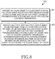
- FIGURE 8 illustrates a method 800 of operating a base station according to an embodiment of this disclosure.
- method 800 includes transmitting an uplink grant to a subscriber station, the uplink grant indicating a first modulation and coding scheme (MCS) value for a first codeword transmission and a second MCS value for a second codeword transmission (block 801).
- Method 800 also includes receiving a multiple-input multiple-output (MIMO) uplink subframe from the subscriber station (block 803).
- the MIMO uplink subframe includes a first subset of layers used for the first codeword transmission and a second subset of layers used for the second codeword transmission.
- Acknowledgement/negative acknowledgement (ACK/NACK) information and rank indication (RI) information are mapped onto both the first subset of layers and the second subset of layers.
- Channel quality information is only mapped onto either the first subset of layers or the second subset of layers.
- the CQI is mapped onto the subset of layers having a higher MCS value.
- the CQI is mapped onto the first subset of layers used for the first codeword transmission.
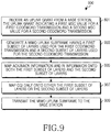
- FIGURE 9 illustrates a method 900 of operating a subscriber station according to an embodiment of this disclosure.
- method 900 includes receiving an uplink grant from a base station, the uplink grant indicating a first modulation and coding scheme (MCS) value for a first codeword transmission and a second MCS value for a second codeword transmission (block 901).
- Method 900 also includes generating a multiple-input multiple-output (MIMO) uplink subframe having a first subset of layers used for the first codeword transmission and a second subset of layers used for the second codeword transmission (block 903).
- MCS modulation and coding scheme
- Method 900 further includes mapping acknowledgement/negative acknowledgement (ACK/NACK) information and rank indication (RI) information onto both the first subset of layers and the second subset of layers (block 905) and mapping channel quality information (CQI) only onto either the first subset of layers or the second subset of layers (block 907).
- Method 900 yet further includes transmitting the MIMO uplink subframe to the base station (block 909).
- the CQI is mapped onto the subset of layers having a higher MCS value.
- the first MCS value is the same as the second MCS value, the CQI is mapped onto the first subset of layers used for the first codeword transmission.
Applications Claiming Priority (2)
| Application Number | Priority Date | Filing Date | Title |
|---|---|---|---|
| US32423110P | 2010-04-14 | 2010-04-14 | |
| US13/071,284 US8670496B2 (en) | 2010-04-14 | 2011-03-24 | Method and system for mapping uplink control information |
Publications (3)
| Publication Number | Publication Date |
|---|---|
| EP2378691A2 EP2378691A2 (en) | 2011-10-19 |
| EP2378691A3 EP2378691A3 (en) | 2014-07-16 |
| EP2378691B1 true EP2378691B1 (en) | 2017-09-27 |
Family
ID=44246263
Family Applications (1)
| Application Number | Title | Priority Date | Filing Date |
|---|---|---|---|
| EP11162372.4A Active EP2378691B1 (en) | 2010-04-14 | 2011-04-14 | Method and apparatus for mapping uplink control information |
Country Status (11)
| Country | Link |
|---|---|
| US (3) | US8670496B2 (zh) |
| EP (1) | EP2378691B1 (zh) |
| JP (1) | JP5838197B2 (zh) |
| KR (1) | KR101776097B1 (zh) |
| CN (1) | CN102939739B (zh) |
| BR (1) | BR112012026186B1 (zh) |
| CA (1) | CA2796310C (zh) |
| ES (1) | ES2653363T3 (zh) |
| MX (1) | MX2012011842A (zh) |
| WO (1) | WO2011129626A2 (zh) |
| ZA (1) | ZA201208527B (zh) |
Families Citing this family (33)
| Publication number | Priority date | Publication date | Assignee | Title |
|---|---|---|---|---|
| US8958494B2 (en) | 2009-03-16 | 2015-02-17 | Interdigital Patent Holdings, Inc. | Data and control multiplexing for uplink MIMO with carrier aggregation and clustered-DFT |
| US9236985B2 (en) * | 2009-04-23 | 2016-01-12 | Qualcomm Incorporated | Method and apparatus for control and data multiplexing in a MIMO communication system |
| KR101407073B1 (ko) * | 2009-10-01 | 2014-06-12 | 한국전자통신연구원 | 다중입력 다중출력 시스템에서 상향링크 데이터용 물리 채널 영역으로 제어 정보를 전송하는 방법 |
| EP3716516B1 (en) | 2010-02-10 | 2022-01-19 | Sun Patent Trust | Terminal and communication method thereof |
| US8699435B2 (en) * | 2010-04-30 | 2014-04-15 | Telefonaktiebolaget Lm Ericsson (Publ) | System and method for allocating transmission resources |
| US9100155B2 (en) * | 2010-05-03 | 2015-08-04 | Qualcomm Incorporated | Method and apparatus for control and data multiplexing in wireless communication |
| RU2580794C2 (ru) * | 2010-05-10 | 2016-04-10 | Телефонактиеболагет Л М Эрикссон (Пабл) | Система и способ выделения ресурсов передачи |
| US8989156B2 (en) * | 2010-06-18 | 2015-03-24 | Sharp Kabushiki Kaisha | Selecting a codeword and determining a symbol length for uplink control information |
| CN102740463A (zh) * | 2011-03-31 | 2012-10-17 | 上海贝尔股份有限公司 | 用于降低无线通信系统中干扰的方法、装置、基站和用户设备 |
| AU2013240631B2 (en) * | 2012-03-26 | 2016-06-09 | Telefonaktiebolaget L M Ericsson (Publ) | Methods of selecting MIMO ranks and related devices |
| EP3589005B1 (en) | 2012-04-27 | 2022-05-11 | NEC Corporation | Radio terminal, radio station and methods |
| JPWO2014020798A1 (ja) * | 2012-07-31 | 2016-07-21 | 日本電気株式会社 | 無線通信装置、並びにharq応答の送信方法及び受信方法 |
| US9318799B2 (en) * | 2013-03-29 | 2016-04-19 | Broadcom Corporation | Wireless communication apparatus and method for controlling antenna radiation patterns based on fading conditions |
| CN106067845A (zh) * | 2015-04-09 | 2016-11-02 | 北京三星通信技术研究有限公司 | 复用上行信息的方法 |
| EP3292647B1 (en) * | 2015-05-06 | 2021-07-07 | Telefonaktiebolaget LM Ericsson (publ) | Inserting and extracting control data using frequency components |
| US11095404B2 (en) * | 2015-07-31 | 2021-08-17 | Qualcomm Incorporated | Multiplexing downlink control information of same aggregation level by coding together |
| WO2017034081A1 (ko) | 2015-08-21 | 2017-03-02 | 엘지전자(주) | 무선 통신 시스템의 데이터 전송 방법 및 장치 |
| CN107926019A (zh) * | 2015-08-31 | 2018-04-17 | 株式会社Ntt都科摩 | 用户终端、无线基站以及无线通信方法 |
| CN108464046B (zh) * | 2016-01-08 | 2022-05-27 | 苹果公司 | 用于自适应下行链路调度和链路适配的装置、系统和方法 |
| US10925005B2 (en) * | 2016-03-25 | 2021-02-16 | Apple Inc. | Uplink power control for 5G systems |
| WO2018056875A1 (en) * | 2016-09-23 | 2018-03-29 | Telefonaktiebolaget Lm Ericsson (Publ) | Transmitting data from a first to second communication device using two different modulation/coding schemes |
| JP6844025B2 (ja) * | 2017-03-20 | 2021-03-17 | エルジー エレクトロニクス インコーポレイティド | 次世代通信システムにおいてコードワードとレイヤをマッピングする方法及びそのための装置 |
| WO2018182242A2 (ko) * | 2017-03-25 | 2018-10-04 | 엘지전자 주식회사 | 무선 통신 시스템에서 위상 잡음 제거를 위한 ptrs 수신 방법 및 그 장치 |
| WO2018201404A1 (en) * | 2017-05-04 | 2018-11-08 | Qualcomm Incorporated | Polar codes for uplink control information |
| CN110754058B (zh) * | 2017-06-14 | 2023-05-05 | 交互数字专利控股公司 | 用于经由上行链路共享数据信道的uci传输的方法、装置 |
| US10574422B2 (en) * | 2017-06-30 | 2020-02-25 | Qualcomm Incorporated | Rate control adaptation |
| CN109246042B (zh) * | 2017-08-25 | 2019-11-19 | 华为技术有限公司 | 一种信号传输的方法、设备及系统 |
| US11177903B2 (en) * | 2017-10-26 | 2021-11-16 | Qualcomm Incorporated | Techniques and apparatuses for implicit uplink control information beta value determination in new radio |
| JP7080619B2 (ja) * | 2017-11-15 | 2022-06-06 | シャープ株式会社 | 端末装置及び通信方法 |
| WO2019104552A1 (en) * | 2017-11-29 | 2019-06-06 | Qualcomm Incorporated | Example uplink control information (uci) layer mapping |
| DE102018201724A1 (de) * | 2018-02-05 | 2019-08-08 | Infineon Technologies Ag | Hall-Sensor-Vorrichtung und Verfahren zum Erfassen eines Magnetfelds |
| IT201900006609A1 (it) * | 2019-05-07 | 2020-11-07 | St Microelectronics Srl | Procedimento di funzionamento di un trasmettitore radio e corrispondente trasmettitore radio |
| CN117915471A (zh) * | 2022-10-10 | 2024-04-19 | 维沃移动通信有限公司 | 上行控制信息传输方法、装置及终端 |
Family Cites Families (30)
| Publication number | Priority date | Publication date | Assignee | Title |
|---|---|---|---|---|
| GB0407663D0 (en) * | 2004-04-03 | 2004-05-05 | Ibm | Variable gain amplifier |
| US20150030058A9 (en) * | 2006-05-17 | 2015-01-29 | Texas Instruments Inc. | Cqi feedback for mimo deployments |
| KR20090113377A (ko) * | 2007-02-28 | 2009-10-30 | 가부시키가이샤 엔티티 도코모 | 기지국장치 및 통신제어방법 |
| RU2009134088A (ru) * | 2007-02-28 | 2011-04-10 | НТТ ДоСоМо, Инк. (JP) | Базовая станция и способ управления связью |
| JP4954782B2 (ja) * | 2007-05-01 | 2012-06-20 | 株式会社エヌ・ティ・ティ・ドコモ | 移動通信システムにおける基地局装置及び方法 |
| US20090116570A1 (en) | 2007-11-02 | 2009-05-07 | Interdigital Patent Holdings, Inc. | Method and apparatus for generating channel quality indicator, precoding matrix indicator and rank information |
| KR100905385B1 (ko) | 2008-03-16 | 2009-06-30 | 엘지전자 주식회사 | 무선통신 시스템에서 제어신호의 효율적인 전송방법 |
| CN102017506B (zh) * | 2008-03-16 | 2014-06-04 | Lg电子株式会社 | 在无线通信系统中执行混合自动重传请求(harq)的方法 |
| US9276787B2 (en) * | 2008-03-28 | 2016-03-01 | Qualcomm Incorporated | Transmission of signaling messages using beacon signals |
| US8811353B2 (en) | 2008-04-22 | 2014-08-19 | Texas Instruments Incorporated | Rank and PMI in download control signaling for uplink single-user MIMO (UL SU-MIMO) |
| KR100987458B1 (ko) | 2008-06-24 | 2010-10-13 | 엘지전자 주식회사 | 상향링크 신호 전송 방법 |
| US8503425B2 (en) | 2008-07-22 | 2013-08-06 | Lg Electronics Inc. | Method for allocating phich and generating reference signal in system using single-user MIMO based on multiple codewords when transmitting uplink |
| US8509161B2 (en) | 2008-08-11 | 2013-08-13 | Sharp Kabushiki Kaisha | Systems and methods for OFDMA and SC-FDMA switching |
| US8625554B2 (en) * | 2009-01-30 | 2014-01-07 | Samsung Electronics Co., Ltd. | System and method for uplink data and control signal transmission in MIMO wireless systems |
| JP5255128B2 (ja) | 2009-02-01 | 2013-08-07 | エルジー エレクトロニクス インコーポレイティド | 多重アンテナ無線通信システムにおいて信号を送信するための資源を割り当てる方法及びその装置 |
| US8644409B2 (en) | 2009-02-11 | 2014-02-04 | Qualcomm Incorporated | Method and apparatus for modulation and layer mapping in a wireless communication system |
| US8958494B2 (en) | 2009-03-16 | 2015-02-17 | Interdigital Patent Holdings, Inc. | Data and control multiplexing for uplink MIMO with carrier aggregation and clustered-DFT |
| KR101746537B1 (ko) | 2009-04-21 | 2017-06-13 | 엘지전자 주식회사 | 무선 통신 시스템에서 제어 신호 송신 방법 및 이를 위한 장치 |
| US9236985B2 (en) | 2009-04-23 | 2016-01-12 | Qualcomm Incorporated | Method and apparatus for control and data multiplexing in a MIMO communication system |
| US8560696B2 (en) * | 2009-04-28 | 2013-10-15 | Intel Corporation | Transmission of advanced-MAP information elements in mobile networks |
| KR101784189B1 (ko) * | 2009-10-28 | 2017-10-12 | 엘지전자 주식회사 | 다중 반송파 시스템에서 상향링크 제어정보 전송 방법 및 장치 |
| JP2013511916A (ja) * | 2009-11-19 | 2013-04-04 | インターデイジタル パテント ホールディングス インコーポレイテッド | マルチキャリアシステムにおけるコンポーネントキャリアのアクティブ化/非アクティブ化 |
| JP5735541B2 (ja) * | 2010-01-18 | 2015-06-17 | エルジー エレクトロニクス インコーポレイティド | 無線通信システムにおいてチャネル品質情報を提供する方法及び装置 |
| EP3716516B1 (en) | 2010-02-10 | 2022-01-19 | Sun Patent Trust | Terminal and communication method thereof |
| WO2011136554A2 (ko) * | 2010-04-27 | 2011-11-03 | 엘지전자 주식회사 | 상향링크 mimo(multiple input multiple output) 전송 방법 및 장치 |
| US9100155B2 (en) * | 2010-05-03 | 2015-08-04 | Qualcomm Incorporated | Method and apparatus for control and data multiplexing in wireless communication |
| US8520572B2 (en) * | 2010-05-05 | 2013-08-27 | Motorola Mobility Llc | Multiplexing control and data on multilayer uplink transmissions |
| US8879513B2 (en) * | 2010-05-12 | 2014-11-04 | Samsung Electronics Co., Ltd. | Uplink transmission apparatus and method for mobile communication system supporting uplink MIMO |
| KR101356532B1 (ko) * | 2010-05-12 | 2014-02-03 | 엘지전자 주식회사 | 다중 안테나 무선 통신 시스템에서 채널 인터리빙 수행 방법 및 이를 위한 장치 |
| WO2012011775A2 (ko) * | 2010-07-22 | 2012-01-26 | 엘지전자 주식회사 | 다중 반송파 시스템에서 상향링크 제어 정보 전송 방법 및 장치 |
-
2011
- 2011-03-24 US US13/071,284 patent/US8670496B2/en active Active
- 2011-04-14 CA CA2796310A patent/CA2796310C/en active Active
- 2011-04-14 JP JP2013504831A patent/JP5838197B2/ja active Active
- 2011-04-14 WO PCT/KR2011/002661 patent/WO2011129626A2/en active Application Filing
- 2011-04-14 BR BR112012026186-0A patent/BR112012026186B1/pt active IP Right Grant
- 2011-04-14 KR KR1020127026081A patent/KR101776097B1/ko active IP Right Grant
- 2011-04-14 EP EP11162372.4A patent/EP2378691B1/en active Active
- 2011-04-14 ES ES11162372.4T patent/ES2653363T3/es active Active
- 2011-04-14 CN CN201180028763.1A patent/CN102939739B/zh active Active
- 2011-04-14 MX MX2012011842A patent/MX2012011842A/es active IP Right Grant
-
2012
- 2012-11-13 ZA ZA2012/08527A patent/ZA201208527B/en unknown
-
2014
- 2014-02-24 US US14/188,219 patent/US8995555B2/en active Active
-
2015
- 2015-03-31 US US14/675,224 patent/US9680624B2/en active Active
Non-Patent Citations (1)
| Title |
|---|
| None * |
Also Published As
| Publication number | Publication date |
|---|---|
| BR112012026186B1 (pt) | 2021-10-05 |
| US8995555B2 (en) | 2015-03-31 |
| KR101776097B1 (ko) | 2017-09-07 |
| EP2378691A3 (en) | 2014-07-16 |
| US20110255619A1 (en) | 2011-10-20 |
| CA2796310C (en) | 2019-04-09 |
| JP5838197B2 (ja) | 2016-01-06 |
| CA2796310A1 (en) | 2011-10-20 |
| US8670496B2 (en) | 2014-03-11 |
| JP2013528029A (ja) | 2013-07-04 |
| ZA201208527B (en) | 2014-01-29 |
| WO2011129626A3 (en) | 2012-01-12 |
| US20150207609A1 (en) | 2015-07-23 |
| MX2012011842A (es) | 2012-11-30 |
| EP2378691A2 (en) | 2011-10-19 |
| WO2011129626A2 (en) | 2011-10-20 |
| KR20130073870A (ko) | 2013-07-03 |
| ES2653363T3 (es) | 2018-02-06 |
| BR112012026186A2 (pt) | 2016-07-05 |
| CN102939739B (zh) | 2017-05-31 |
| US20140169311A1 (en) | 2014-06-19 |
| US9680624B2 (en) | 2017-06-13 |
| CN102939739A (zh) | 2013-02-20 |
Similar Documents
| Publication | Publication Date | Title |
|---|---|---|
| EP2378691B1 (en) | Method and apparatus for mapping uplink control information | |
| US10292140B2 (en) | Method and system for indicating the transmission mode for uplink control information | |
| US9768934B2 (en) | Method and system for uplink acknowledgement signaling in carrier-aggregated wireless communication systems | |
| EP2443778B1 (en) | Method and system for indicating method used to scramble dedicated reference signals | |
| US8971261B2 (en) | Method and system for transmitting channel state information in wireless communication systems | |
| US8467799B2 (en) | Method and system for assigning physical uplink control channel (PUCCH) resources | |
| EP2343850B1 (en) | Method and system for enabling resource block bundling in lte-a systems | |
| EP2540006B1 (en) | Method and system for indicating an enabled transport block |
Legal Events
| Date | Code | Title | Description |
|---|---|---|---|
| AK | Designated contracting states |
Kind code of ref document: A2 Designated state(s): AL AT BE BG CH CY CZ DE DK EE ES FI FR GB GR HR HU IE IS IT LI LT LU LV MC MK MT NL NO PL PT RO RS SE SI SK SM TR |
|
| AX | Request for extension of the european patent |
Extension state: BA ME |
|
| PUAI | Public reference made under article 153(3) epc to a published international application that has entered the european phase |
Free format text: ORIGINAL CODE: 0009012 |
|
| RAP1 | Party data changed (applicant data changed or rights of an application transferred) |
Owner name: SAMSUNG ELECTRONICS CO., LTD. |
|
| PUAL | Search report despatched |
Free format text: ORIGINAL CODE: 0009013 |
|
| AK | Designated contracting states |
Kind code of ref document: A3 Designated state(s): AL AT BE BG CH CY CZ DE DK EE ES FI FR GB GR HR HU IE IS IT LI LT LU LV MC MK MT NL NO PL PT RO RS SE SI SK SM TR |
|
| AX | Request for extension of the european patent |
Extension state: BA ME |
|
| RIC1 | Information provided on ipc code assigned before grant |
Ipc: H04L 25/03 20060101ALI20140606BHEP Ipc: H04L 5/00 20060101ALI20140606BHEP Ipc: H04L 1/00 20060101AFI20140606BHEP Ipc: H04L 1/18 20060101ALI20140606BHEP |
|
| 17P | Request for examination filed |
Effective date: 20150116 |
|
| RBV | Designated contracting states (corrected) |
Designated state(s): AL AT BE BG CH CY CZ DE DK EE ES FI FR GB GR HR HU IE IS IT LI LT LU LV MC MK MT NL NO PL PT RO RS SE SI SK SM TR |
|
| GRAP | Despatch of communication of intention to grant a patent |
Free format text: ORIGINAL CODE: EPIDOSNIGR1 |
|
| INTG | Intention to grant announced |
Effective date: 20170407 |
|
| GRAS | Grant fee paid |
Free format text: ORIGINAL CODE: EPIDOSNIGR3 |
|
| GRAA | (expected) grant |
Free format text: ORIGINAL CODE: 0009210 |
|
| AK | Designated contracting states |
Kind code of ref document: B1 Designated state(s): AL AT BE BG CH CY CZ DE DK EE ES FI FR GB GR HR HU IE IS IT LI LT LU LV MC MK MT NL NO PL PT RO RS SE SI SK SM TR |
|
| REG | Reference to a national code |
Ref country code: GB Ref legal event code: FG4D |
|
| REG | Reference to a national code |
Ref country code: CH Ref legal event code: EP |
|
| REG | Reference to a national code |
Ref country code: AT Ref legal event code: REF Ref document number: 932900 Country of ref document: AT Kind code of ref document: T Effective date: 20171015 |
|
| REG | Reference to a national code |
Ref country code: IE Ref legal event code: FG4D |
|
| REG | Reference to a national code |
Ref country code: DE Ref legal event code: R096 Ref document number: 602011041843 Country of ref document: DE |
|
| PG25 | Lapsed in a contracting state [announced via postgrant information from national office to epo] |
Ref country code: FI Free format text: LAPSE BECAUSE OF FAILURE TO SUBMIT A TRANSLATION OF THE DESCRIPTION OR TO PAY THE FEE WITHIN THE PRESCRIBED TIME-LIMIT Effective date: 20170927 Ref country code: SE Free format text: LAPSE BECAUSE OF FAILURE TO SUBMIT A TRANSLATION OF THE DESCRIPTION OR TO PAY THE FEE WITHIN THE PRESCRIBED TIME-LIMIT Effective date: 20170927 Ref country code: LT Free format text: LAPSE BECAUSE OF FAILURE TO SUBMIT A TRANSLATION OF THE DESCRIPTION OR TO PAY THE FEE WITHIN THE PRESCRIBED TIME-LIMIT Effective date: 20170927 Ref country code: HR Free format text: LAPSE BECAUSE OF FAILURE TO SUBMIT A TRANSLATION OF THE DESCRIPTION OR TO PAY THE FEE WITHIN THE PRESCRIBED TIME-LIMIT Effective date: 20170927 Ref country code: NO Free format text: LAPSE BECAUSE OF FAILURE TO SUBMIT A TRANSLATION OF THE DESCRIPTION OR TO PAY THE FEE WITHIN THE PRESCRIBED TIME-LIMIT Effective date: 20171227 |
|
| REG | Reference to a national code |
Ref country code: NL Ref legal event code: MP Effective date: 20170927 |
|
| REG | Reference to a national code |
Ref country code: ES Ref legal event code: FG2A Ref document number: 2653363 Country of ref document: ES Kind code of ref document: T3 Effective date: 20180206 |
|
| REG | Reference to a national code |
Ref country code: LT Ref legal event code: MG4D |
|
| REG | Reference to a national code |
Ref country code: AT Ref legal event code: MK05 Ref document number: 932900 Country of ref document: AT Kind code of ref document: T Effective date: 20170927 |
|
| PG25 | Lapsed in a contracting state [announced via postgrant information from national office to epo] |
Ref country code: RS Free format text: LAPSE BECAUSE OF FAILURE TO SUBMIT A TRANSLATION OF THE DESCRIPTION OR TO PAY THE FEE WITHIN THE PRESCRIBED TIME-LIMIT Effective date: 20170927 Ref country code: BG Free format text: LAPSE BECAUSE OF FAILURE TO SUBMIT A TRANSLATION OF THE DESCRIPTION OR TO PAY THE FEE WITHIN THE PRESCRIBED TIME-LIMIT Effective date: 20171227 Ref country code: LV Free format text: LAPSE BECAUSE OF FAILURE TO SUBMIT A TRANSLATION OF THE DESCRIPTION OR TO PAY THE FEE WITHIN THE PRESCRIBED TIME-LIMIT Effective date: 20170927 Ref country code: GR Free format text: LAPSE BECAUSE OF FAILURE TO SUBMIT A TRANSLATION OF THE DESCRIPTION OR TO PAY THE FEE WITHIN THE PRESCRIBED TIME-LIMIT Effective date: 20171228 |
|
| REG | Reference to a national code |
Ref country code: FR Ref legal event code: PLFP Year of fee payment: 8 |
|
| PG25 | Lapsed in a contracting state [announced via postgrant information from national office to epo] |
Ref country code: NL Free format text: LAPSE BECAUSE OF FAILURE TO SUBMIT A TRANSLATION OF THE DESCRIPTION OR TO PAY THE FEE WITHIN THE PRESCRIBED TIME-LIMIT Effective date: 20170927 |
|
| PG25 | Lapsed in a contracting state [announced via postgrant information from national office to epo] |
Ref country code: RO Free format text: LAPSE BECAUSE OF FAILURE TO SUBMIT A TRANSLATION OF THE DESCRIPTION OR TO PAY THE FEE WITHIN THE PRESCRIBED TIME-LIMIT Effective date: 20170927 Ref country code: CZ Free format text: LAPSE BECAUSE OF FAILURE TO SUBMIT A TRANSLATION OF THE DESCRIPTION OR TO PAY THE FEE WITHIN THE PRESCRIBED TIME-LIMIT Effective date: 20170927 |
|
| PG25 | Lapsed in a contracting state [announced via postgrant information from national office to epo] |
Ref country code: IS Free format text: LAPSE BECAUSE OF FAILURE TO SUBMIT A TRANSLATION OF THE DESCRIPTION OR TO PAY THE FEE WITHIN THE PRESCRIBED TIME-LIMIT Effective date: 20180127 Ref country code: AT Free format text: LAPSE BECAUSE OF FAILURE TO SUBMIT A TRANSLATION OF THE DESCRIPTION OR TO PAY THE FEE WITHIN THE PRESCRIBED TIME-LIMIT Effective date: 20170927 Ref country code: SM Free format text: LAPSE BECAUSE OF FAILURE TO SUBMIT A TRANSLATION OF THE DESCRIPTION OR TO PAY THE FEE WITHIN THE PRESCRIBED TIME-LIMIT Effective date: 20170927 Ref country code: SK Free format text: LAPSE BECAUSE OF FAILURE TO SUBMIT A TRANSLATION OF THE DESCRIPTION OR TO PAY THE FEE WITHIN THE PRESCRIBED TIME-LIMIT Effective date: 20170927 Ref country code: EE Free format text: LAPSE BECAUSE OF FAILURE TO SUBMIT A TRANSLATION OF THE DESCRIPTION OR TO PAY THE FEE WITHIN THE PRESCRIBED TIME-LIMIT Effective date: 20170927 |
|
| REG | Reference to a national code |
Ref country code: DE Ref legal event code: R097 Ref document number: 602011041843 Country of ref document: DE |
|
| PG25 | Lapsed in a contracting state [announced via postgrant information from national office to epo] |
Ref country code: DK Free format text: LAPSE BECAUSE OF FAILURE TO SUBMIT A TRANSLATION OF THE DESCRIPTION OR TO PAY THE FEE WITHIN THE PRESCRIBED TIME-LIMIT Effective date: 20170927 |
|
| PLBE | No opposition filed within time limit |
Free format text: ORIGINAL CODE: 0009261 |
|
| STAA | Information on the status of an ep patent application or granted ep patent |
Free format text: STATUS: NO OPPOSITION FILED WITHIN TIME LIMIT |
|
| PG25 | Lapsed in a contracting state [announced via postgrant information from national office to epo] |
Ref country code: PL Free format text: LAPSE BECAUSE OF FAILURE TO SUBMIT A TRANSLATION OF THE DESCRIPTION OR TO PAY THE FEE WITHIN THE PRESCRIBED TIME-LIMIT Effective date: 20170927 |
|
| 26N | No opposition filed |
Effective date: 20180628 |
|
| PG25 | Lapsed in a contracting state [announced via postgrant information from national office to epo] |
Ref country code: SI Free format text: LAPSE BECAUSE OF FAILURE TO SUBMIT A TRANSLATION OF THE DESCRIPTION OR TO PAY THE FEE WITHIN THE PRESCRIBED TIME-LIMIT Effective date: 20170927 Ref country code: MC Free format text: LAPSE BECAUSE OF FAILURE TO SUBMIT A TRANSLATION OF THE DESCRIPTION OR TO PAY THE FEE WITHIN THE PRESCRIBED TIME-LIMIT Effective date: 20170927 |
|
| REG | Reference to a national code |
Ref country code: CH Ref legal event code: PL |
|
| REG | Reference to a national code |
Ref country code: BE Ref legal event code: MM Effective date: 20180430 |
|
| REG | Reference to a national code |
Ref country code: IE Ref legal event code: MM4A |
|
| PG25 | Lapsed in a contracting state [announced via postgrant information from national office to epo] |
Ref country code: LU Free format text: LAPSE BECAUSE OF NON-PAYMENT OF DUE FEES Effective date: 20180414 |
|
| PG25 | Lapsed in a contracting state [announced via postgrant information from national office to epo] |
Ref country code: LI Free format text: LAPSE BECAUSE OF NON-PAYMENT OF DUE FEES Effective date: 20180430 Ref country code: CH Free format text: LAPSE BECAUSE OF NON-PAYMENT OF DUE FEES Effective date: 20180430 Ref country code: BE Free format text: LAPSE BECAUSE OF NON-PAYMENT OF DUE FEES Effective date: 20180430 |
|
| PG25 | Lapsed in a contracting state [announced via postgrant information from national office to epo] |
Ref country code: IE Free format text: LAPSE BECAUSE OF NON-PAYMENT OF DUE FEES Effective date: 20180414 |
|
| PG25 | Lapsed in a contracting state [announced via postgrant information from national office to epo] |
Ref country code: MT Free format text: LAPSE BECAUSE OF NON-PAYMENT OF DUE FEES Effective date: 20180414 |
|
| PG25 | Lapsed in a contracting state [announced via postgrant information from national office to epo] |
Ref country code: TR Free format text: LAPSE BECAUSE OF FAILURE TO SUBMIT A TRANSLATION OF THE DESCRIPTION OR TO PAY THE FEE WITHIN THE PRESCRIBED TIME-LIMIT Effective date: 20170927 |
|
| PG25 | Lapsed in a contracting state [announced via postgrant information from national office to epo] |
Ref country code: PT Free format text: LAPSE BECAUSE OF FAILURE TO SUBMIT A TRANSLATION OF THE DESCRIPTION OR TO PAY THE FEE WITHIN THE PRESCRIBED TIME-LIMIT Effective date: 20170927 Ref country code: HU Free format text: LAPSE BECAUSE OF FAILURE TO SUBMIT A TRANSLATION OF THE DESCRIPTION OR TO PAY THE FEE WITHIN THE PRESCRIBED TIME-LIMIT; INVALID AB INITIO Effective date: 20110414 |
|
| PG25 | Lapsed in a contracting state [announced via postgrant information from national office to epo] |
Ref country code: CY Free format text: LAPSE BECAUSE OF FAILURE TO SUBMIT A TRANSLATION OF THE DESCRIPTION OR TO PAY THE FEE WITHIN THE PRESCRIBED TIME-LIMIT Effective date: 20170927 Ref country code: MK Free format text: LAPSE BECAUSE OF NON-PAYMENT OF DUE FEES Effective date: 20170927 |
|
| PG25 | Lapsed in a contracting state [announced via postgrant information from national office to epo] |
Ref country code: AL Free format text: LAPSE BECAUSE OF FAILURE TO SUBMIT A TRANSLATION OF THE DESCRIPTION OR TO PAY THE FEE WITHIN THE PRESCRIBED TIME-LIMIT Effective date: 20170927 |
|
| PGFP | Annual fee paid to national office [announced via postgrant information from national office to epo] |
Ref country code: FR Payment date: 20230321 Year of fee payment: 13 |
|
| PGFP | Annual fee paid to national office [announced via postgrant information from national office to epo] |
Ref country code: IT Payment date: 20230321 Year of fee payment: 13 |
|
| PGFP | Annual fee paid to national office [announced via postgrant information from national office to epo] |
Ref country code: ES Payment date: 20230530 Year of fee payment: 13 Ref country code: DE Payment date: 20230320 Year of fee payment: 13 |
|
| PGFP | Annual fee paid to national office [announced via postgrant information from national office to epo] |
Ref country code: GB Payment date: 20240320 Year of fee payment: 14 |